EP4303386B1 - Flügelportal - Google Patents
Flügelportal Download PDFInfo
- Publication number
- EP4303386B1 EP4303386B1 EP23182981.3A EP23182981A EP4303386B1 EP 4303386 B1 EP4303386 B1 EP 4303386B1 EP 23182981 A EP23182981 A EP 23182981A EP 4303386 B1 EP4303386 B1 EP 4303386B1
- Authority
- EP
- European Patent Office
- Prior art keywords
- stop
- rotation
- axis
- screen
- swing gate
- Prior art date
- Legal status (The legal status is an assumption and is not a legal conclusion. Google has not performed a legal analysis and makes no representation as to the accuracy of the status listed.)
- Active
Links
Images


Classifications
-
- E—FIXED CONSTRUCTIONS
- E05—LOCKS; KEYS; WINDOW OR DOOR FITTINGS; SAFES
- E05D—HINGES OR SUSPENSION DEVICES FOR DOORS, WINDOWS OR WINGS
- E05D7/00—Hinges or pivots of special construction
- E05D7/08—Hinges or pivots of special construction for use in suspensions comprising two spigots placed at opposite edges of the wing, especially at the top and the bottom, e.g. trunnions
- E05D7/081—Hinges or pivots of special construction for use in suspensions comprising two spigots placed at opposite edges of the wing, especially at the top and the bottom, e.g. trunnions the pivot axis of the wing being situated near one edge of the wing, especially at the top and bottom, e.g. trunnions
-
- E—FIXED CONSTRUCTIONS
- E05—LOCKS; KEYS; WINDOW OR DOOR FITTINGS; SAFES
- E05D—HINGES OR SUSPENSION DEVICES FOR DOORS, WINDOWS OR WINGS
- E05D11/00—Additional features or accessories of hinges
- E05D11/06—Devices for limiting the opening movement of hinges
-
- E—FIXED CONSTRUCTIONS
- E05—LOCKS; KEYS; WINDOW OR DOOR FITTINGS; SAFES
- E05F—DEVICES FOR MOVING WINGS INTO OPEN OR CLOSED POSITION; CHECKS FOR WINGS; WING FITTINGS NOT OTHERWISE PROVIDED FOR, CONCERNED WITH THE FUNCTIONING OF THE WING
- E05F15/00—Power-operated mechanisms for wings
- E05F15/60—Power-operated mechanisms for wings using electrical actuators
- E05F15/603—Power-operated mechanisms for wings using electrical actuators using rotary electromotors
- E05F15/611—Power-operated mechanisms for wings using electrical actuators using rotary electromotors for swinging wings
-
- E—FIXED CONSTRUCTIONS
- E05—LOCKS; KEYS; WINDOW OR DOOR FITTINGS; SAFES
- E05Y—INDEXING SCHEME ASSOCIATED WITH SUBCLASSES E05D AND E05F, RELATING TO CONSTRUCTION ELEMENTS, ELECTRIC CONTROL, POWER SUPPLY, POWER SIGNAL OR TRANSMISSION, USER INTERFACES, MOUNTING OR COUPLING, DETAILS, ACCESSORIES, AUXILIARY OPERATIONS NOT OTHERWISE PROVIDED FOR, APPLICATION THEREOF
- E05Y2201/00—Constructional elements; Accessories therefor
- E05Y2201/20—Brakes; Disengaging means; Holders; Stops; Valves; Accessories therefor
- E05Y2201/224—Stops
-
- E—FIXED CONSTRUCTIONS
- E05—LOCKS; KEYS; WINDOW OR DOOR FITTINGS; SAFES
- E05Y—INDEXING SCHEME ASSOCIATED WITH SUBCLASSES E05D AND E05F, RELATING TO CONSTRUCTION ELEMENTS, ELECTRIC CONTROL, POWER SUPPLY, POWER SIGNAL OR TRANSMISSION, USER INTERFACES, MOUNTING OR COUPLING, DETAILS, ACCESSORIES, AUXILIARY OPERATIONS NOT OTHERWISE PROVIDED FOR, APPLICATION THEREOF
- E05Y2600/00—Mounting or coupling arrangements for elements provided for in this subclass
- E05Y2600/10—Adjustable
- E05Y2600/14—Adjustable with position retaining means
-
- E—FIXED CONSTRUCTIONS
- E05—LOCKS; KEYS; WINDOW OR DOOR FITTINGS; SAFES
- E05Y—INDEXING SCHEME ASSOCIATED WITH SUBCLASSES E05D AND E05F, RELATING TO CONSTRUCTION ELEMENTS, ELECTRIC CONTROL, POWER SUPPLY, POWER SIGNAL OR TRANSMISSION, USER INTERFACES, MOUNTING OR COUPLING, DETAILS, ACCESSORIES, AUXILIARY OPERATIONS NOT OTHERWISE PROVIDED FOR, APPLICATION THEREOF
- E05Y2600/00—Mounting or coupling arrangements for elements provided for in this subclass
- E05Y2600/10—Adjustable
- E05Y2600/30—Adjustment motion
- E05Y2600/33—Stepwise motion
-
- E—FIXED CONSTRUCTIONS
- E05—LOCKS; KEYS; WINDOW OR DOOR FITTINGS; SAFES
- E05Y—INDEXING SCHEME ASSOCIATED WITH SUBCLASSES E05D AND E05F, RELATING TO CONSTRUCTION ELEMENTS, ELECTRIC CONTROL, POWER SUPPLY, POWER SIGNAL OR TRANSMISSION, USER INTERFACES, MOUNTING OR COUPLING, DETAILS, ACCESSORIES, AUXILIARY OPERATIONS NOT OTHERWISE PROVIDED FOR, APPLICATION THEREOF
- E05Y2900/00—Application of doors, windows, wings or fittings thereof
- E05Y2900/40—Application of doors, windows, wings or fittings thereof for gates
Definitions
- the present invention relates to a swing gate.
- the present invention relates to the field of swing gates comprising, where appropriate, a motorized drive device setting a screen in motion following a pivoting movement.
- the motorized drive device allows the screen to be moved between at least a first position and at least a second position by pivoting about a vertical axis. In the absence of a motorized drive device, or in the event of its failure, the swing gate can be driven to pivot by hand.
- the document FR-A1-2 964 135 teaches, moreover, to produce a hinge by means of a base on which is received an ear, which can be molded and whose body is provided with a through housing intended to receive an adjustment screw.
- This hinge does not allow to limit the pivoting of a screen of a swing gate, so that a stop must be provided for this purpose, in addition to this hinge.
- the present invention aims to resolve the aforementioned drawbacks and to propose a swing gate making it possible to precisely define an end-of-travel position for pivoting a screen, by means of a reliable, inexpensive and compact device, without having to resort to an electromechanical arm actuator.
- the base further comprises at least one circular rack, the circular rack being centered on the axis of rotation.
- the base which is located under the upright and which supports it, defines both the guide bearing of the upright in pivoting and the means of fixing the end stop of the pivoting travel of the screen.
- the support device is compact and is arranged at the foot of the upright, ensuring a triple function of taking up the weight of the screen, guiding the pivoting of the screen and defining an end-of-travel position for the screen.
- the stop pin provides a limit switch function without protruding radially from the screen upright while the base is positioned under this upright. This limits the size of the support device.
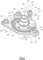
- Installation 1 includes a swing gate 2 and a motorized drive device 3.
- the swing gate 2 is installed at the level of an opening 7 made in a fence, in particular between two pillars 6 of the fence, of which only one pillar 6 is shown in the figure.
- Figure 1 The swing gate 2 allows the opening 7 to be selectively closed.
- the opening 7 is made in a building or enclosure.
- the swing gate 2 of installation 1 is a barrier that pivots in a horizontal plane.
- the swing gate 2 includes at least one screen 5.
- the swing gate 2 includes a single screen 5 shown in the Figure 1 .
- the swing gate 2 comprises two screens 5.
- the screen 5 is configured to be mounted, in other words is mounted, pivoting about a rotation axis Z, in particular in an assembled configuration of the installation 1.
- the rotation axis Z is theoretically vertical, in the assembled configuration of the installation 1.
- the motorized drive device 3 sets the screen 5 of the swing gate 2 in motion, between at least a first position and at least a second position, corresponding respectively to a closed position and an open position of the screen 5.
- the screen 5 is a movable closing element, such as a leaf, a grille or any other equivalent material.
- the swing gate 2 in particular the motorized drive device 3, comprises an electromechanical actuator 4.
- This electromechanical actuator is, for example, of the type known from the document FR-A1-3 096 069 .
- the screen 5 comprises at least one upright 22.
- the upright 22 is aligned, in other words is configured to be aligned, on the rotation axis Z, in particular in an assembled configuration of the swing gate 2.
- the electromechanical actuator 4 is configured to be arranged, in other words is arranged, at least partly inside the upright 22, in particular in the assembled configuration of the swing gate 2.
- the electromechanical actuator 4 is said to be integrated into the upright 22.
- the electromechanical actuator 4 is hidden in the upright 22, the electromechanical actuator 4 is protected from the weather, in particular from rain, in addition the aesthetics and the size of the swing gate 2 are improved.
- the electromechanical actuator 4 is configured to move the swing gate 2, in particular the upright 22 and the screen 5, relative to a fixed structure, in particular relative to the pillar 6 of the fence.
- the swing gate 2 in particular the upright 22 and the screen 5, is driven in movement by the motorized drive device 3 and, more particularly, by the electromechanical actuator 4.
- the amount 22 is hollow and, preferably, vertical.
- the amount 22 is made by means of a profile.
- the amount 22 may be made of metallic material, such as, for example, steel or aluminum, or of plastic material.
- the upright 22 is configured to support, in other words supports, the screen 5, in particular in the assembled configuration of the swing gate 2.
- the amount 22 is configured to be fixed, in other words is fixed, to the screen 5, in particular in the assembled configuration of the installation 1.
- the fixing of the upright 22 to the screen 5 is implemented by welding, by screwing or by any other fixing means.
- the swing gate 2 comprises at least one interface plate 25a, 25b.
- the or each interface plate 25a, 25b is configured to be mounted, in other words is mounted, at one end 22a, 22b of the upright 22, in particular in the assembled configuration of the swing gate 2.
- each interface plate 25a, 25b is secured to one end 22a, 22b of the upright 22.
- the swing gate 2 comprises a first interface plate 25a, which may also be called the upper interface plate, and a second interface plate 25b, which may also be called the lower interface plate.
- the first interface plate 25a is mounted at a first end 22a, which may also be called the upper end, of the upright 22.
- the second interface plate 25b is mounted at a second end 22b, which may also be called the lower end, of the upright 22.
- the second end 22b of the upright 22 is opposite the first end 22a of the upright 22.
- the or each interface plate 25a, 25b is configured to be fixed, in other words is fixed, to the upright 22, by means of fixing elements, in particular in the assembled configuration of the swing gate 2.
- each of the first and second interface plates 25a, 25b is fixed to the upright 22 by means of screw fixing elements, i.e. fixing screws represented by their axis lines 27, as illustrated in figures 3 And 8 , in particular four in number.
- the number and type of fixing elements are not limiting and may be different. They may be, for example, two, three or more than five in number and/or be elastic snap-fastening fixing elements.
- each fixing screw 27 is mounted through a passage opening 127 provided in one of the first and second interface plates 25a, 25b and screwed into a screw barrel, not shown, provided in the upright 22.
- the swing gate 2 further comprises a retaining device 23 and a support device 24 for the screen 2 and, in particular, for the upright 22.
- the retaining device 23 is a device for retaining the screen 5 relative to the pillar 6.
- the retaining device 23 retains, in other words is configured to retain, the upright 22 from above, with the possibility of pivoting around the rotation axis Z, in particular in the assembled configuration of the swing gate 2.
- the retaining device 23 is mounted above the upright 22.
- the retaining device 23 may also be referred to as a “high pivot”.
- the support device 24 supports, in other words is configured to support, the upright 22 from below, with the possibility of pivoting around the rotation axis Z, in particular in the assembled configuration of the swing gate 2.
- the support device 24 takes up the weight force of the screen 5.
- the support device 24 may also be referred to as a “low pivot”.
- the swing gate 2 includes both the retaining 23 and support 24 devices.
- the retaining device 23 can be integrated into a swing gate 2 independently of the support device 24, that is to say independently of the characteristics of the present invention which relate to the support device 24.
- a swing gate 2 comprising the retaining device 23 without the supporting device 24, or vice versa, is therefore possible and also covered by this description.
- At least the retaining device 23 is integral with the fixed structure, in particular the pillar 6 of the fence, in particular at the level of an upper part of the pillar 6, in the assembled configuration of the installation 1, as illustrated in Figure 1 .
- the retaining device 23 makes it possible to create a connection between the swing gate 2, in particular the upright 22, and the pillar 6 of the fence.
- the retaining device 23 is mounted above the upright 22, in particular above its first end 22a.
- the retaining device 23 comprises a plate 232 and, optionally, a cover 234.
- the cover 234 covers, in other words is configured to cover, the plate 232, in particular in the assembled configuration of the swing gate 2.
- the cover 324 improves the aesthetics of the retaining device 23 and protects the plate 232 against bad weather, pollution and shocks.
- the retaining device 23, more particularly the plate 232 is configured to be fixed, in other words is fixed, to the fixed structure, in particular to the pillar 6 of the fence, by means of fixing elements, in particular screw fixing elements, such as threaded rods 236 sealed or screwed into the pillar 6, on which nuts are screwed on, not shown.
- each threaded rod 236 is mounted through a passage opening 232A, 232B, 232C formed through a bottom plate 232D of the plate 232 which is pressed against the pillar 6, in particular in the assembled configuration of the installation 1.
- Each passage opening 232A, 232B, 232C is oblong in shape. The largest dimension of the passage openings 232A and 232B is vertical in the mounted configuration of the plate 232 on the pillar 6, while the largest dimension of the passage opening 232C is horizontal. This facilitates the positioning of the plate 232 against the pillar 6, while respecting a predefined orientation, as explained below.
- the support device 24 is secured to the ground.
- the support device 24 makes it possible to create a connection between the swing gate 2, in particular the upright 22, and the ground.
- the support device 24 comprises a base 242 and, optionally, a cover 244.
- the cover 244 covers, in other words is configured to cover, the base 242, in particular in the assembled configuration of the installation 1.
- the cover 244 improves the aesthetics of the support device 24 and protects the base 242 against bad weather, pollution and shocks.
- the cover 244 has the function of limiting the risks of injury for the user of the installation 1, by preventing a person from getting a hand or foot trapped, in particular between the base 242 and the screen 5 and, more particularly, between a stop 264 and a stop pin 280 of the support device 24.
- the support device 24, more particularly the base 242 is configured to be fixed, in other words is fixed, to the ground by means of fixing elements, in particular screw fixing elements, such as threaded rods 246 sealed or screwed into the ground, onto which nuts 248 are screwed.
- the base 242 supports the weight of the swing gate 2, in particular the screen 5.
- the screen 5, in particular the upright 22, is configured to be mounted, in other words is mounted, pivoting, around the axis of rotation Z, relative to the pillar 6 of the fence.
- the screen 5, including the upright 22, is rotated by the electromechanical actuator 4 and is movable between the open position and the closed position, which are respectively end-of-travel positions for pivoting the screen 5.
- the electromechanical actuator 4 comprises at least one electric motor, not shown.
- the electromechanical actuator 4 is secured to the upright 22.
- the electromechanical actuator 4 is configured to be positioned and fixed, in other words is positioned and fixed in the assembled configuration of the swing gate 2, relative to the first interface plate 25a, by means of positioning elements 77 and fixing elements, not shown.
- the electromechanical actuator 4, in particular a yoke 41 of the electromechanical actuator 4 is positioned relative to the first interface plate 25a by means of the positioning elements 77 by interlocking, in particular four in number. Furthermore, the electromechanical actuator 4, in particular the yoke 41 of the electromechanical actuator 4, is fixed to the first interface plate 25a, by means of screw-on fastening elements, in particular four fastening screws, not shown.
- each positioning pin 77 is inserted into a housing, not shown, provided in the first interface plate 25a.
- each fixing screw is mounted through a passage opening 178 provided in the first interface plate 25a and screwed into a screw hole 78 provided in the yoke 41 of the electromechanical actuator 4.
- the number and type of positioning elements and fixing elements are not limiting and may be different. They may be, for example, two, three or greater than or equal to five respectively.
- the motorized drive device 3 further comprises an electronic control unit 12.
- the electromechanical actuator 4 is controlled by the electronic control unit 12 of the motorized drive device 3.
- the electronic control unit 12 of the motorized drive device 3 is remote from the electromechanical actuator 4, in particular outside the swing gate 2.
- the electronic control unit 12 is arranged inside an electrical box 79.
- the electronic control unit 12 of the motorized drive device 3 is offset relative to the electromechanical actuator 4 inside the swing gate 2 and, more particularly, inside the upright 22.
- the electronic control unit 12 of the motorized drive device 3 is arranged inside the electromechanical actuator 4 and, more particularly, a casing of the electromechanical actuator 4.
- the electronic control unit 12 of the motorized drive device 3 comprises hardware and/or software means.
- the hardware means may comprise at least one microcontroller, not shown.
- the electronic control unit 12 of the motorized drive device 3 is capable of operating the electric motor of the electromechanical actuator 4 and, in particular, of enabling the electric motor to be supplied with electrical energy by means of an electrical power supply cable 9.
- the electronic control unit 12 of the motorized drive device 3 controls, in particular, the electric motor, so as to open or close the screen 5 of the swing gate 2.
- the motorized drive device 3 also comprises a control interface 13, 14 functionally connected to the electronic control unit 12 of the motorized drive device 3.
- control interface 13, 14 may be a local control unit 13 and/or a central control unit 14.
- the local control unit 13 or central control unit 14 is connected, by a wireless link, to the electronic control unit 12 of the motorized drive device 3.
- connection between the local control unit 13 or central control unit 14 and the electronic control unit 12 is wired.
- the local control unit 13 can be connected, by wired or wireless connection, to the central control unit 14.
- the electronic control unit 12 can be controlled from the local control unit 13 or central control unit 14.
- the electronic control unit 12 comprises a first communication module 15, as illustrated in Figure 1 , in particular for receiving control orders, the control orders being issued by an order transmitter, such as the local control unit 13 or central control unit 14, these orders being intended to control the motorized drive device 3.
- the first communication module 15 of the electronic control unit 12 is of the wireless type.
- the first communication module 15 is configured to receive radio control orders.
- the first communication module 15 can also allow the reception of control orders transmitted by wired means.
- the local 13 or central 14 control unit comprises a control keyboard.
- the control keyboard of the local 13 or central 14 control unit comprises one or more selection elements 16 and, optionally, one or more display elements 17.
- the selection elements may include push buttons or touch-sensitive keys.
- the display elements may include light-emitting diodes and/or a display, for example LCD (acronym for the English term “Liquid Crystal Display”) or TFT (acronym for the English term “Thin Film Transistor”).
- LCD liquid Crystal Display
- TFT thin Film Transistor
- the selection and display elements may also be implemented using a touch screen.
- the local control unit 13 or central control unit 14 allows a user to adjust parameters and/or control the motorized drive device 3 and, in particular, the electromechanical actuator 4 associated with the swing gate 2, by pressing one of the selection elements 16.
- the electronic control unit 12, the local control unit 13 or the central control unit 14 can be in communication with a weather station located on or near a piece of land delimited by the fence and including, in particular, one or more sensors that can be configured to determine, for example, a temperature, a wind speed or even a brightness.
- a weather station located on or near a piece of land delimited by the fence and including, in particular, one or more sensors that can be configured to determine, for example, a temperature, a wind speed or even a brightness.
- this weather station is remote from this enclosure or this building.
- the electronic control unit 12, the local control unit 13 and/or the central control unit 14 can also be in communication with a server 18, so as to control the motorized drive device 3 according to data made available remotely via a communication network, in particular an internet network which can be connected to the server 18.
- a communication network in particular an internet network which can be connected to the server 18.
- the local control unit 13 or central control unit 14 comprises at least one second communication module 19.
- the second communication module 19 of the local control unit 13 or central control unit 14 is configured to transmit, in other words emit, control orders, in particular by wireless means, for example radioelectric, or by wired means.
- the second communication module 19 of the local control unit 13 or central control unit 14 can also be configured to receive, in other words receives, control orders, in particular via the same means.
- the second communication module 19 of the local control unit 13 or central control unit 14 is configured to communicate, in other words communicates, with the first communication module 15 of the electronic control unit 12.
- the second communication module 19 of the local control unit 13 or central control unit 14 exchanges control orders with the first communication module 15 of the electronic control unit 12, either in a either unidirectionally or bidirectionally.
- the local control unit 13 is a control point, which may be mobile or fixed.
- a mobile control point may be a remote control, a smartphone or a tablet.
- a fixed control point may be a control box intended to be fixed to a facade of a wall of a building or of the pillar 6.
- the local control unit 13 or central control unit 14 further comprises a controller 20.
- the motorized drive device 3, in particular the electronic control unit 12, is preferably configured to execute movement control orders, in particular closing and opening, of the screen 5 of the swing gate 2. These control orders can be issued, in particular, by the local control unit 13 or by the central control unit 14.
- the motorized drive device 3 can be controlled by the user, for example by receiving a control command corresponding to pressing the or one of the selection elements 16 of the local 13 or central 14 control unit.
- the motorized drive device 3 can also be controlled automatically, for example by receiving a control command corresponding to at least one signal from at least one sensor and/or a signal from a clock of the electronic control unit 12, in particular the microcontroller.
- the sensor and/or the clock can be integrated into the local control unit 13 or the central control unit 14.
- the electromechanical actuator 4 is supplied with electrical energy by means of the electrical power supply cable 9, represented by a dotted line, only on the figures 1 , 2 And 5
- the power supply cable 9 extends, in part, inside the upright 22 and passes through an opening 25b1 provided in the second interface plate 25b.
- the base 242 is preferably made by metal casting.
- the fact that the base 242 is obtained by casting is particularly advantageous in terms of cost price, since it is then not necessary to implement machining rework steps. This is also advantageous in terms of strength and mechanical stability. The service life of the support device 24 is thus improved.
- the base 242 is intended to be immobilized relative to the fixed part of the installation 1, in particular relative to the ground, as explained above, and to serve as a pivot for screen 5. It can, as such, be described as a “toad”.
- the base 242 is a single piece.
- the base 242 comprises at least one bearing 250 for guiding the upright 22 in pivoting around the axis of rotation Z, in other words a cylindrical hub with a circular section, centered on a central axis A24 of the support device 24.
- V250 denotes a volume of the bearing 250, in particular internal, given that the bearing 250 is hollow.
- a ring 252 is mounted around the bearing 250 and makes it possible to center the second interface plate 25b around the central axis A24, which coincides with the rotation axis Z, in particular in the assembled configuration of the swing gate 2.
- the bearing 250 constitutes a guide bearing for the second interface plate 25b, therefore for the upright 22, pivoting around the rotation axis Z.
- the bearing 250 is stepped. This makes it possible to define the position of the ring 252 along the central axis A24.
- the part of the bearing 250, which defines the guide bearing for the upright 22, is the part of smaller diameter, which is surrounded by the ring 252, in particular in the assembled configuration of the swing gate 2.
- the base 242 further comprises a plurality of openings 256.
- Each opening 256 is an opening for the passage of a fixing element 246 to the ground of the base 242.
- the base 242 comprises several legs 254, in this case three in number.
- Each of the legs 254 comprises at least one of the openings 256.
- each opening 256 is a notch for receiving one of the threaded rods 246.
- Each opening 256 opens outwards, that is to say on the side of the lug 254 opposite the central axis A24.
- the open or outwardly opening nature of the openings 256 facilitates the installation of the base 242 on the ground, while the threaded rods 246 are already sealed or screwed into place.
- the open or through nature of the openings 256 allows longitudinal adjustment of the position of the base 242 in a direction parallel to the largest dimension of the openings 256.
- the base 242 comprises several markers 258, in this case four in number.
- the markers 258 are regularly distributed, in particular at 90°, around the central axis A24 and therefore the axis of rotation Z.
- the markers 258 make it possible to position the retaining device 23 vertically, in particular by means of a laser.
- the number of markers is other than four, for example equal to two, three or five.
- the base 242 further comprises a circular rack 260.
- the circular rack 260 is centered on the central axis A24 and therefore on the rotation axis Z.
- a circular rack is a series of indentations arranged one after the other, in other words a succession of indentations, following a circular arrangement, in particular according to a regular pitch, the circular arrangement being defined by a fictitious circle.
- the circular rack 260 is formed by a succession of hollow housings 262, distributed regularly around the central axis A24, in particular over 360°.
- the circular rack 260 comprises thirty-six hollow housings 262 spaced angularly, two by two, by an angle ⁇ equal to 10° and which form the indentations of the circular rack 260.
- the number of recessed housings is different and the value of the angle between two recessed housings is adapted accordingly.
- the number of recessed housings may be, for example, 24 or 48, in which case the angle ⁇ is 15° or 7.5° respectively.
- the support device 24 further comprises the stop 264.
- the stop 264 is immobilized, or is configured to be immobilized, on the base 242 in a predetermined angular position around the central axis A24 and therefore the rotation axis Z, by cooperation with the circular rack 260, in particular in an assembled configuration of the support device 24.
- the support device 24 further comprises first immobilization elements.
- the first immobilizing elements are reliefs 268.
- the reliefs 268 are arranged on the stop 264 and intended to cooperate, in other words cooperate, with the circular rack 260, so as to block the stop 264 on the circular rack 260, in a direction orthoradial to the axis of rotation Z, in particular in the assembled configuration of the swing gate 2.
- the stop 264 includes the reliefs 268, in other words teeth, visible at the Figure 7 , the geometry and positioning of which are provided so that these reliefs 268 can engage at the same time in adjacent hollow housings 262 of the circular rack 260.
- the stop 264 is a part obtained by metal casting.
- the stop 264 comprises five reliefs 268.
- the number of reliefs of the stop is different, for example equal to one, two, three, four or greater than and equal to six.
- the reliefs 268 of the stop 264 have the same angular spacing between them as the hollow housings 262 of the circular rack 260.
- the base 242 further comprises a groove 270, in particular annular.
- the groove 270 surrounds the bearing 250 and the marks 258 around the central axis A24, in particular over 360°. Radially to the central axis A24, the groove 270 is located between the marks 258 and the circular rack 260.
- the stop 264 comprises a heel 272.
- the heel 272 is engaged in the groove 270, when the reliefs 268 of the stop 264 are received in the hollow housings 262 of the circular rack 260.
- the heel 272 makes it possible to guide the stop 264 in a rotational movement around the central axis A24, relative to the circular rack 260, when the reliefs 268 are not engaged in the hollow housings 262.
- heel 272 makes it possible to block the stop 264 relative to the base 242, in particular by wedge effect, as is apparent from the explanations which follow.
- the support device 24 further comprises a second immobilizing element.
- the second immobilizing element is a pressure screw 274.
- the pressure screw 274 exerts, in other words is configured to exert, on the stop 264 a radial force at the axis of rotation Z.
- the support device 24 further comprises the pressure screw 274.
- the pressure screw 274 is screwed into a tapped hole 276 of the stop 264 and bears, otherwise is configured to bear, against an external radial surface S250 of the bearing 250, when the stop 264 is blocked relative to the base 242.
- the surface S250 is not covered by the ring 252 when it is mounted on the bearing 250.
- the pressure screw 274 exerts on the stop 264 a radial force at the central axis A24 and therefore at the axis of rotation Z and centrifugal.
- the support of the pressure screw 274 against the surface S250 has the effect of pressing the heel 272 against an external radial edge of the groove 270.
- the stop 264 is firmly immobilized, in a predetermined position by the cooperation of the reliefs 268 and the hollow housings 262, on the base 242.
- the stop 264 can be immobilized on the circular rack 260 in any of the thirty-six predetermined positions defined by the cooperation of the reliefs 268 with the hollow housings 262.
- the support device 24 further comprises the stop pin 280.
- the stop pin 280 is secured to the upright 22 and is configured to come to bear, in other words comes to bear, against the stop 264, at the end of the pivoting travel of the screen 5 around the rotation axis Z.
- the stop pin 280 has the function of blocking the rotation of the screen 5 around the rotation axis Z by coming to bear against a lateral surface S264 of the stop 264, when the screen 5 reaches the end of its pivoting travel around the rotation axis Z, in an opening direction, that is to say when the screen 5 reaches its open position.
- the stop pin 280 may have the function of blocking the rotation of the screen 5 around the rotation axis Z when the screen 5 reaches its closed position.
- the groove 270 takes up the radial forces at the central axis A24 coming from the stop 264, through the heel 272, and the reliefs 268 of the stop 264 take up the forces coming from the screen 5 when the latter is in the end-of-travel position, through the stop pin 280.
- the stop pin 280 is mounted, in other words is configured to be mounted, on the second interface plate 25b, in particular in the assembled configuration of the swing gate 2. As the second interface plate 25b is fixed to the upright 22, in particular by the fixing screws 27, the stop pin 280 is secured to the upright 22 through the second interface plate 25b.
- the stop pin 280 is secured directly to the upright 22, that is to say without passing through the second interface plate 25b.
- the stop pin 280 comprises a rod 282, in particular threaded.
- the rod 282 is configured to pass through, in other words cross, the second interface plate 25b, in particular through an orifice 284 formed in the second plate. interface 25b, in the assembled configuration of the swing gate 2.
- the stop pin 280 further comprises a nut 288, in particular a braked nut.
- the nut 288 makes it possible to immobilize the stop pin 280 on the second interface plate 25b.
- two washers 285, 286 are provided to be arranged, in other words are arranged, on either side of the second interface plate 25b, along the axis of rotation Z, in particular in the assembled configuration of the swing gate 2.
- the stop pin 280 in particular the rod 282, comprises a wedge 290.
- the wedge 290 bears, in other words is configured to bear, against the stop 264, in particular in the assembled configuration of the support device 24.
- the wedge 290 is preferably installed at one end of the rod 282, which constitutes the lower end of the stop pin 280, particularly in the assembled configuration of the support device 24.
- the rod 282 and the wedge 290 are in one piece.
- parts 282 and 290 are manufactured separately and assembled together to form the stop pin 280.
- A280 a longitudinal axis of the stop pin 280, which is a central axis of the rod 282.
- the rod 282 is held in position, otherwise is configured to be held in position, on the second interface plate 25b by means of the nut 288, with the possibility of rotation of the wedge 290 relative to the second interface plate 25b, around the longitudinal axis A280 of the stop pin 280.
- the shim 290 comprises at least a first bearing surface S290A against the stop 264 and a second bearing surface S290B against the stop 264.
- d A a first distance, measured perpendicular to the longitudinal axis A280, between the first support surface S290A and the longitudinal axis A280. This first distance d A has a first value.
- d B a second distance d B , measured perpendicular to the longitudinal axis A280, between the second support surface S290B and the longitudinal axis A280.
- This second distance d B has a second value. The second value is different from the first value.
- the wedge 290 comprises four bearing surfaces, in particular parallel to the longitudinal axis A280, namely the bearing surfaces S290A, S290B, S290C, S290D visible on the insert A) of the Figure 7 .
- These bearing surfaces S290A, S290B, S290C, S290D are separated two by two by chamfers 292.
- the bearing surfaces S290A, S290B, S290C, S290D are perpendicular two by two. In other words, each of these bearing surfaces S290A, S290B, S290C, S290D is perpendicular to the two bearing surfaces to which it is connected by a chamfer 292 and parallel to the opposite bearing surface.
- third and fourth distances measured respectively perpendicular to the longitudinal axis A280, between the third bearing surface S290C and the longitudinal axis A280 and between the fourth bearing surface S290D and the longitudinal axis A280.
- the distances d A , d B , d C , d D between these bearing surfaces S290A, S290B, S290C, S290D and the longitudinal axis A280, measured perpendicular to the longitudinal axis A280, are different two by two.
- the bearing surfaces S290A, S290B, S290C, S290D extend at different distances from the longitudinal axis A280, in the plane of the insert A) at the Figure 7 .
- the wedge 290 can be arranged, with respect to the longitudinal axis A280 in four positions.
- one of the bearing surfaces S290A, S290B, S290C, S290D comes to bear, otherwise is configured to come to bear, against the stop 264, at the end of the pivoting travel of the screen 5 around the rotation axis Z.
- the stop position of the upright 22 when the stop pin 280 comes to bear against the stop 264 is defined by the position of the longitudinal axis A280 with respect to the circular rack 260, that is to say by its position around the axis of rotation Z and the central axis A24, which are the same.
- This stop position corresponds to the open position of the screen 2 or, alternatively, to the closed position of the screen 2.
- the position of the longitudinal axis A280 relative to the rotation axis Z and the central axis A24 depends on the distance between the surface S264 of the stop 264 and the longitudinal axis A280, this distance being equal, in practice, to one of the distances d A , d B , d C , d D , depending on the orientation of the wedge 290 around the longitudinal axis A280.
- the wedge 290 can be arranged, with respect to the longitudinal axis A280, in four positions, preferably angularly offset by 90° relative to one another, which each correspond to the facing of one of the bearing surfaces S290A, S290B, S290C, S290D and the surface S264 of the stop 264.
- the distances d A , d B , d C , d D are preferably chosen so that the different angular positions of the wedge 290 around the longitudinal axis A280, depending on the support of the corresponding support surfaces S290A, S290B, S290C, S290D against the surface S264 of the stop 264, correspond to an angular offset of a predetermined value, which may be, for example, 2.5°, between each of the positions.
- the use of the shim 290 and the choice of its orientation around the longitudinal axis A280 therefore makes it possible to refine the adjustment precision when the screen 5 is at the end of its travel, that is to say when the stop pin 280 is pressing against the stop 264.
- the nut 288 is a lock nut, it can be tightened moderately on the rod 282. This allows an installer to manipulate the wedge 290 to rotate it about the longitudinal axis A280 when selecting the bearing surface S290A, S290B, S290C, S290D which must come to bear against the surface S264 of the stop 264, without having to dismantle the second interface plate 25b relative to the upright 22. This facilitates the commissioning of the installation 1.
- the rotation of the wedge 290 around the longitudinal axis A280 can be carried out manually by the installer, in particular using a tool, such as, for example, a flat spanner.
- the volume V250 constitutes a passage for the electrical power supply cable 9 of the electromechanical actuator 4.
- the electrical power supply cable 9 can pass through the pillar 6 or pass through a sole (not shown), in which the threaded rods 246 are sealed or screwed, then rise up into the upright 22 by passing through the volume V250 of the bearing 250 and through the opening 25b1 of the second interface plate 25b, to supply electrical energy to the electromechanical actuator 4, in particular its electric motor.
- the electrical power supply cable 9 is thus protected against the risks of untimely cutting, including during the pivoting of the screen 5.
- the electromechanical actuator 4 further comprises an output shaft 8.
- the output shaft 8 extends upwards, from the first end 22a of the upright 22.
- the output shaft 8 of the electromechanical actuator 4 is aligned on a longitudinal axis A8 coincident with the axis of rotation Z, in particular of the upright 22, in the assembled configuration of the swing gate 2.
- the output shaft 8 of the electromechanical actuator 4 i.e. the shaft constituting a fixed point of the motorized drive device 3, coincides with the axis of rotation Z, in particular of the upright 22.
- the electromechanical actuator 4 extends in the direction of the rotation axis Z.
- the first interface plate 25a comprises an opening 34 for the passage of the output shaft 8 of the electromechanical actuator 4.
- the output shaft 8 is arranged at least partly outside the upright 22, in the assembled configuration of the swing gate 2.
- the output shaft 8 of the electromechanical actuator 4 is configured to be integral, in other words is integral, with the retaining device 23, in particular in the assembled configuration of the installation 1.
- A232 denotes a longitudinal axis of the plate 232, which is perpendicular to the bottom plate 232D of the plate 232.
- the plate 232 comprises a housing 232E.
- the housing 232E is a housing for receiving one end 8A of the output shaft 8 of the electromechanical actuator 4, extending along the axis of rotation Z, from the first end 22a of the upright 22.
- the end 8A of the output shaft 8 of the electromechanical actuator 4 is engaged and retained, in other words is configured to be engaged and retained, inside the housing 232E, in particular in the assembled configuration of the swing gate 2.
- the end 8A of the output shaft 8 of the actuator electromechanical 4 is fixed, in other words is configured to be fixed, to the retaining device 23 by means of at least one element 35, 36, in particular a screw fixing element, in the assembled configuration of the swing gate 2.
- the plate 232 is equipped with at least a first element 35, 36, the first element 35, 36 being a fixing element, in other words a retaining element, of the end 8A of the output shaft 8 in the housing 232E.
- the end 8A of the output shaft 8 is provided with two flats 8C, one of which is visible at figure 9 .
- D 8 the diameter of the output shaft 8, measured parallel to the flats 8C
- l 8 the width of the output shaft 8, measured between the flats 8C.
- l 232 the width of the housing 232E measured perpendicular to the longitudinal axis A232.
- the width /232 is strictly greater than the width l 8 and strictly less than the diameter D 8 . This imposes the angular orientation of the output shaft 8 around the axis of rotation Z when its end 8A is received in the housing 232E.
- the end 8A of the output shaft 8 of the electromechanical actuator 4 is retained in the housing 232E by means of a fixing screw 35 and a nut 36.
- the fixing screw 35 is mounted through a passage opening 8B provided in the output shaft 8 of the electromechanical actuator 4 and passes through two passage holes 232F provided in the plate 232, with the interposition of two washers 37, 38. Then, the nut 36 is screwed onto the fixing screw 35 until it comes under pressure on the plate 232.
- the 232 plate is a single piece.
- the plate 232 further comprises an opening 232G, which makes it possible to lighten it, without significantly reducing its mechanical properties.
- the opening 232G is preferably disposed between the housing 232E and the bottom plate 232D.
- the plate 232 further comprises a stiffening rib 232H, which surrounds the opening 232G and which connects to the base plate 232D.
- the through holes 232F are oblong, with their largest direction parallel to the longitudinal axis A232. This allows an adjustment of the position of the output shaft 8 in the housing 232E, parallel to this longitudinal axis A232. Once this adjustment has been made, tightening the nut 36 allows the fixing screw 35 to be held in position by report to the 232 plate.
- the plate 232 is equipped with at least one second element 238.
- the second element 238 is an element for adjusting the verticality of the screen 5, in particular by bearing on the end 8A of the output shaft 8 arranged in the housing 232E of the plate 232.
- the second element 238 is a pressure screw.
- the pressure screw is screwed into a tapped hole 232J of the plate 232. This makes it possible to immobilize the output shaft 8 in the housing 232E, bearing against a wall of the plate 232, in particular which separates the housing 232E from the opening 232G.
- the pressure screw forming the second element 238 makes it possible to adjust the verticality of the screen 5, in particular quickly and precisely, before the output shaft 8 is locked in position in the housing 232E of the plate 232, by the first element consisting of the fixing screw 35 and the nut 36.
- the plate 232 further comprises a surface S232, in particular a flat surface.
- the surface S232 is a support surface of a level, not shown, in the mounted configuration of the plate 232 on the pillar 6.
- the surface S232 is intended to receive a level as a support. This makes it possible to adjust the positioning of the plate 232 on the pillar 6 before tightening nuts on the threaded rods 236, by moving the plate 232 if necessary until the level indicates that the surface S232 is horizontal. This ensures correct positioning of the plate 232, in particular the fact that the housing 232E is correctly oriented so that the output shaft 8 is received there with its longitudinal axis A8, in particular vertical.
- a washer 237 and a spacer 239 are interposed, along the axis of rotation Z, between the first interface plate 25a and the plate 232.
- this washer 237 and this spacer 239 surround the end 8A of the output shaft 8 and protect against bad weather and pollution by closing the opening 34 and the passage openings 178.
- the plate 232 is produced by casting metal, in particular steel or aluminum alloy, or by casting synthetic material, in particular a composite material.
- the casting process minimises the cost of obtaining this 232 plate.
- the casting process is particularly advantageous in this respect, compared to a machining process.
- the plate 232 can be produced partially by molding, with one or more machining operations, in particular to produce the housing 232E or the tapped hole 232J.
- the plate 232 further comprises at least one first relief 232K, 232L, 232M.
- the cover 234 comprises at least one second relief 234A, 234B, 234C.
- the cover 234 is held, in other words is configured to be held, on the plate 232 by cooperation of shapes of the second relief 234A, 234B, 234C with the first relief 232K, 232L, 232M, in particular in an assembled configuration of the retaining device 23.
- the cover 234 comprises a projecting element 234A and two tabs 234B, 234C, forming second reliefs of the cover 234.
- the bottom plate 232D of the plate 232 comprises a notch 232K and two slides 232L, 232M, forming first reliefs of the plate 232.
- the notch 232K and the slides 232L, 232M are configured to receive, in other words receive, respectively the projecting element 234A and the two tabs 234B, 234C, in the mounted configuration of the cover 234 on the plate 232.
- the cover 234 is attached to the plate 232 by a simple vertical translation directed downwards, represented by the arrow F11 at Figure 11 This translation is carried out parallel to the face of pillar 6 on which plate 232 is fixed.
- the electromechanical actuator 4 further comprises a reducer not shown.
- the reducer comprises at least one reduction stage.
- This reduction stage may be an epicyclic type gear train.
- the type and number of reduction stages of the reducer are not limiting.
- the reducer is of the reversible type.
- the reducer is configured to be mounted, in other words is mounted, between the electric motor and the output shaft 8, in particular in an assembled configuration of the electromechanical actuator 4.
- the electric motor is configured to reversibly drive the output shaft 8 in rotation, through the reducer, and, more particularly, the screen 5, that is to say in a clockwise direction of rotation and in a counterclockwise direction of rotation.
- the motorized drive device 3 further comprises the unlocking device 26.
- the unlocking device 26 is configured to be accessible, in other words is accessible, in particular in the assembled configuration of the swing gate 2, so as to allow the screen 5 to be moved manually relative to the fixed structure, in particular the pillar 6 of the fence, in particular in the event of failure of the electromechanical actuator 4 or of a cut in its power supply.
- the unlocking device 26 is configured to be arranged, otherwise is arranged, at least partly inside the upright 22, in particular in the assembled configuration of the swing gate 2.
- the unlocking device 26 is at least partially hidden inside the upright 22, so as to improve the aesthetic appearance of the installation 1.
- the electromechanical actuator 4 further comprises a brake (not shown), in particular an electric brake.
- the brake makes it possible, in particular, to block the motorized drive device 3, in particular the electromechanical actuator 4, when the screen 5 is in the closed position.
- the electrobrake is configured to be mounted, in other words is mounted, on the electric motor of the electromechanical actuator 4, in particular on a casing of the electric motor, in the assembled configuration of the electromechanical actuator 4.
- the base which is located under the upright and which supports it, defines both the guide bearing of the upright in pivoting and means for fixing the end stop of the pivoting travel of the screen.
- the support device is compact and is arranged at the foot of the upright, ensuring a triple function of taking up the weight of the screen, guiding the pivoting of the screen and defining an end-of-travel position for the screen.
- the stop pin provides a limit switch function without protrude radially from the screen upright while the base is positioned under this upright. This limits the size of the support device.
- the shim mounted on the stop pin makes it possible to improve the precision of the definition of the end-of-travel position of the screen.
- the invention is described above and represented by the figures in the case where it includes a motorized drive device 3 comprising an electromechanical actuator 4.
- the invention is however applicable to an installation 1 without the motorized drive device 3, that is to say in which the screen 5 is moved by hand.
- the output shaft 8 which extends along the axis of rotation Z, from the first end 22a of the upright 22 is a shaft movable in rotation relative to the first interface plate 25a, in particular through a bearing.
- two stops 264 can be mounted on the base 242, a first stop 264 defining with the stop pin 280 a first end-of-travel position corresponding to the open position of the screen 5, while the second stop 264 defines with the stop pin 280 a second end-of-travel position corresponding to the closed position of the screen 5.
- the number of surfaces of the wedge 290, capable of coming to bear against the stop 264 is other than four. It may be equal to two, three, five or more.
- the reliefs 268 of the stop 264 formed by teeth are replaced by other reliefs, of different shapes.
- the circular rack 260 is provided with projecting reliefs and the stop 264 is provided with hollow reliefs, in which the projecting reliefs of the circular rack 260 can be engaged.
- the circular rack 260 extends only over a portion of a circular arc around the central axis A24.
- several circular racks 260 can be provided on the base 242.
- they can advantageously be of the same diameter and in continuity with each other, so as to form portions of a circle, or even concentric.
- the number of openings 256 of the base 242 is strictly greater than three.
- the openings 256 of the base 242 are replaced by openings which do not open outwards when moving away from the central axis A24.
Landscapes
- Engineering & Computer Science (AREA)
- Mechanical Engineering (AREA)
- Gates (AREA)
- Refuge Islands, Traffic Blockers, Or Guard Fence (AREA)
- Pivots And Pivotal Connections (AREA)
Claims (10)
- Flügeltor (2), mindestens umfassend:- einen Flügel (5), wobei der Flügel (5) schwenkbar um eine Drehachse (Z) montiert ist, der Flügel (5) umfassend mindestens einen Pfosten (22), wobei der Pfosten (22) auf die Drehachse (Z) ausgerichtet ist, und- eine Stützvorrichtung (24), wobei die Stützvorrichtung (24) den Pfosten (22) von unten mit Möglichkeit eines Schwenkens um die Drehachse (Z) stützt, die Stützvorrichtung (22) mindestens umfassend einen Sockel (242) umfasst, der Sockel (242) umfassend mindestens ein Lager (250) zum Führen des Pfostens (22) beim Schwenken um die Drehachse (Z),
dadurch gekennzeichnet,- dass der Sockel (242) ferner mindestens eine kreisförmige Zahnstange (260) umfasst, wobei die kreisförmige Zahnstange (260) auf der Drehachse (Z) zentriert ist,- und dass die Stützvorrichtung (24) mindestens Folgendes umfasst:• einen Anschlag (264), wobei der Anschlag (264) an dem Sockel (242) in einer vorbestimmten Winkelposition um die Drehachse (Z) durch Zusammenwirken mit der kreisförmigen Zahnstange (260) fixiert ist, und• einen Anschlagstift (280), wobei der Anschlagstift (280) fest mit dem Pfosten (22) verbunden ist und konfiguriert ist, um an dem Ende des Schwenkwegs des Flügels (5) um die Drehachse (Z) an dem Anschlag (264) in Anlage zu kommen. - Flügeltor (2) nach Anspruch 1, dadurch gekennzeichnet,- dass der Anschlagstift (280) einen Keil (290) umfasst, wobei der Keil (290) konfiguriert ist, um an dem Ende des Schwenkwegs des Flügels (5) um die Drehachse (Z) an dem Anschlag (264) in Anlage gebracht wird, - dass der Keil (290) mindestens Folgendes umfasst:- eine erste Anlagefläche (S290A) an dem Anschlag (264), und- eine zweite Anlagefläche (S290B) an dem Anschlag (264),- dass ein senkrecht zu einer Längsachse (A280) des Anschlagstifts (280) gemessener erster Abstand (dA) zwischen der ersten Anlagefläche (S290A) und der Längsachse (A280) des Anschlagstifts (280) einen ersten Wert aufweist,- dass ein senkrecht zu der Längsachse (A280) des Anschlagstifts (280) gemessener zweiter Abstand (dB) zwischen der zweiten Anlagefläche (S290B) und der Längsachse (A280) des Anschlagstifts (280) einen zweiten Wert aufweist, wobei sich der zweite Wert von dem ersten Wert unterscheidet,- und dass der Keil (290) in Bezug auf die Längsachse (A280) des Anschlagstifts (280) ausrichtbar ist zwischen mindestens:- einer ersten Winkelposition, in der die erste Anlagefläche (S290A) an dem Ende des Schwenkwegs des Flügels (5) um die Drehachse (Z) an dem Anschlag (264) in Anlage kommt, und- einer zweiten Winkelposition, in der die zweite Anlagefläche (S290B) an dem Ende des Schwenkwegs des Flügels (5) um die Drehachse (Z) an dem Anschlag (264) in Anlage kommt.
- Flügeltor (2) nach Anspruch 2, dadurch gekennzeichnet,- dass der Keil (290) vier verschiedene Anlageflächen (S290A, S290B, S290C, S290D) umfasst,- dass Abstände (dA, dB, dC, dD) zwischen diesen Anlageflächen (S290A, S290B, S290C, S290D) und der Längsachse (A280) des Anschlagstifts (280), gemessen senkrecht zu der Längsachse (A280), paarweise verschieden sind,- dass der Keil (290) in Bezug auf die Längsachse (A280) des Anschlagstifts (280) in vier Positionen angeordnet werden kann,- und dass in jeder der Positionen des Keils (290) eine der vier Anlageflächen (S290A, S290B, S290C, S290D) an dem Ende des Schwenkwegs des Flügels (5) um die Drehachse (Z) an dem Anschlag (264) in Anlage kommt.
- Flügeltor (2) nach einem der vorherigen Ansprüche, dadurch gekennzeichnet,- dass die Stützvorrichtung (24) ferner Feststellelemente (268, 274) des Anschlags (264) an dem Sockel (242) umfasst,• und dass die Feststellelemente (268, 274) mindestens Folgendes umfassen:• Erhebungen (268), wobei die Erhebungen (268) an dem Anschlag (264) ausgebildet sind und dazu bestimmt sind, mit der kreisförmigen Zahnstange (260) zusammenzuwirken, um den Anschlag (264) an der kreisförmigen Zahnstange (260) in einer Richtung orthoradial zu der Drehachse (Z) zu blockieren, und• eine Druckschraube (274), wobei die Druckschraube (274) auf den Anschlag (264) eine Kraft radial zu der Drehachse (Z) ausübt.
- Flügeltor (2) nach einem der vorherigen Ansprüche, dadurch gekennzeichnet,- dass das Flügeltor (2) ferner mindestens eine Schnittstellenplatte (25b) umfasst, wobei die Schnittstellenplatte (25b) fest mit einem unteren Ende (22b) des Pfostens (22) verbunden ist,- und dass der Anschlagstift (280) an der Schnittstellenplatte (25b) montiert ist.
- Flügeltor (2) nach Anspruch 5, dadurch gekennzeichnet,- dass der Anschlagstift (280) mindestens Folgendes umfasst:• einen Stab (282), wobei der Stab (282) die Schnittstellenplatte (25b) durchquert, und• eine Mutter (288),- und dass der Stab (282) mittels der Mutter (288) an der Schnittstellenplatte (25b) in Position gehalten wird, wobei der Keil (290) in Bezug auf die Schnittstellenplatte (25b) um die Längsachse (A280) des Arretierstifts (280) drehbar ist.
- Flügeltor (2) nach einem der vorherigen Ansprüche, dadurch gekennzeichnet,- dass das Flügeltor (2) ferner einen elektromechanischen Aktuator (4) umfasst, wobei der elektromechanische Aktuator (4) zumindest teilweise innerhalb des Pfostens (22) angeordnet ist,- und dass der Sockel (242) ferner ein Volumen (V250) für den Durchgang eines Stromversorgungskabels (9) des elektromechanischen Aktuators (4) umfasst, und/oder- dass die Sockel (242) ferner mehrere Markierungen (258) umfasst, wobei die Markierungen (258) gleichmäßig um die Drehachse (Z) verteilt sind, und/oder- dass der Sockel (242) ferner eine Vielzahl von Öffnungen (256) umfasst, wobei jede Öffnung (256) eine Durchgangsöffnung für ein Bodenbefestigungselement (246) des Sockels (242) ist.
- Flügeltor (2) nach einem der vorherigen Ansprüche, dadurch gekennzeichnet,- dass das Flügeltor (2) ferner eine Haltevorrichtung (23) des Flügels (5) in Bezug auf einen Pfeiler (6) umfasst,- dass die Haltevorrichtung (23) oberhalb des Pfostens (22) montiert ist,- dass die Haltevorrichtung (23) mindestens eine Platine (232) umfasst, wobei die Platine (232) einstückig ist und an dem Pfeiler (6) befestigt ist,- und dass die Platine (232) mindestens eine Aufnahme (232E) umfasst, wobei die Aufnahme (232E) eine Aufnahme zum Aufnehmen eines Endes (8A) einer Welle (8) ist, die sich entlang der Drehachse (Z) von einem oberen Ende (22a) des Pfostens (22) aus erstreckt.
- Flügeltor (2) nach Anspruch 8, dadurch gekennzeichnet,- dass die Platine (232) eine Oberfläche (S232) umfasst, wobei die Oberfläche (S232) eine Anlagefläche für eine Wasserwaage ist, und/oder- dass die Platine (232) mit mindestens einem ersten Element (35, 36) ausgestattet ist, wobei das erste Element (35, 36) ein Element zum Halten des Endes (8A) der Welle (8) in der Aufnahme (232E) ist, und/oder- dass die Platine (232) mit mindestens einem zweiten Element (238) ausgestattet ist, wobei das zweite Element (238) ein Element zum Einstellen der Senkrechten des Flügels (5) ist, und/oder- dass die Platine (232) mindestens eine erste Erhebung (232K, 232L, 232M) umfasst,- dass die Haltevorrichtung (23) ferner eine Abdeckung (234) umfasst, wobei die Abdeckung (234) mindestens eine zweite Erhebung (234A, 234B, 234C) umfasst,- und dass die Abdeckung (234) durch formschlüssiges Zusammenwirken der zweiten Erhebung (234A, 234B, 234C) mit der ersten Erhebung (232K, 232L, 232M) auf der Platine (232) gehalten wird.
- Flügeltor (2) nach einem der vorherigen Ansprüche, dadurch gekennzeichnet, dass der Sockel (242) ein einteiliges Gussteil ist.
Applications Claiming Priority (1)
| Application Number | Priority Date | Filing Date | Title |
|---|---|---|---|
| FR2206737A FR3137402B1 (fr) | 2022-07-04 | 2022-07-04 | Portail battant |
Publications (2)
| Publication Number | Publication Date |
|---|---|
| EP4303386A1 EP4303386A1 (de) | 2024-01-10 |
| EP4303386B1 true EP4303386B1 (de) | 2025-03-19 |
Family
ID=83280239
Family Applications (1)
| Application Number | Title | Priority Date | Filing Date |
|---|---|---|---|
| EP23182981.3A Active EP4303386B1 (de) | 2022-07-04 | 2023-07-03 | Flügelportal |
Country Status (3)
| Country | Link |
|---|---|
| EP (1) | EP4303386B1 (de) |
| FR (1) | FR3137402B1 (de) |
| PL (1) | PL4303386T3 (de) |
Family Cites Families (4)
| Publication number | Priority date | Publication date | Assignee | Title |
|---|---|---|---|---|
| FR2673219A1 (fr) | 1991-02-27 | 1992-08-28 | Lauzier Sa | Dispositif de butee pour portail. |
| ITTV20060195A1 (it) | 2006-10-31 | 2008-05-01 | Nice Spa | Attuatore rotativo. |
| FR2964135B1 (fr) | 2010-08-26 | 2012-09-07 | Financ Tirard Sas | Gond de portail reglable |
| FR3096069B1 (fr) | 2019-05-16 | 2022-01-21 | Somfy Activites Sa | Dispositif d’entraînement motorisé d’une installation de fermeture et installation de fermeture associée |
-
2022
- 2022-07-04 FR FR2206737A patent/FR3137402B1/fr active Active
-
2023
- 2023-07-03 PL PL23182981.3T patent/PL4303386T3/pl unknown
- 2023-07-03 EP EP23182981.3A patent/EP4303386B1/de active Active
Also Published As
| Publication number | Publication date |
|---|---|
| EP4303386A1 (de) | 2024-01-10 |
| FR3137402B1 (fr) | 2024-07-05 |
| PL4303386T3 (pl) | 2025-05-26 |
| FR3137402A1 (fr) | 2024-01-05 |
Similar Documents
| Publication | Publication Date | Title |
|---|---|---|
| EP2376714B1 (de) | Einstiegsöffnung mit rahmen und damit verbundenem deckel | |
| EP0612090A2 (de) | Drehbetätigungseinrichtung für einen Leistungsschalter | |
| EP2957705A1 (de) | Elektromechanisches stellglied und heiminstallation, die ein solches stellglied umfasst | |
| EP0743053A1 (de) | Sicherheits- und Kontrollvorrichtung der Verriegelung einer Radnabe, insbesondere für Rollstuhl | |
| FR2849817A1 (fr) | Retroviseur pour vehicule comportant un miroir monte pivotant sur deux axes perpendiculaires | |
| EP3830374A1 (de) | Mechanisches modul zur filterung von schwingungen, elektromechanischer aktuator mit einem solchen mechanischen modul zum filtern von schwingungen und verschluss, abdeckung oder sonnenschutzanlage mit einem solchen elektromechanischen aktuator | |
| EP4303386B1 (de) | Flügelportal | |
| EP2248988A1 (de) | Aufhängung eines Torflügels für abschüssiges Gelände | |
| EP2824518B1 (de) | Mikrometerregulierung des Spiels der Triebfeder eines Uhrwerks | |
| EP3239598B1 (de) | Drehbares leuchtmodul | |
| EP3418483B1 (de) | Regulierungsverfahren der motorisierten antriebsvorrichtung eines drehtors | |
| FR3013914A1 (fr) | Support d'appareillage comportant un accessoire de griffage pour sa fixation a une boite murale, accessoire de griffage, ensemble de griffage et appareillage electrique associes | |
| EP3306415B1 (de) | Mechanisches uhrwerk mit erfassung der gangreserve | |
| EP3239447B1 (de) | Motorisierte antriebsvorrichtung eines schiebetors, und heimschliessanlage, die eine solche vorrichtung umfasst | |
| EP2360339B1 (de) | Stellglied mit Arm für Fenster- oder Türflügel | |
| FR3096069A1 (fr) | Dispositif d’entraînement motorisé d’une installation de fermeture et installation de fermeture associée | |
| EP2919077A2 (de) | Antriebsvorrichtung einer analoganzeige, insbesondere eines datumsanzeigerings | |
| FR2932016A1 (fr) | Antenne autoportante pour station de base et ensemble pour systeme d'antenne integrant une telle antenne. | |
| EP4346036B1 (de) | Schutzzubehör für die tür eines schaltschranks, tür und schaltschrank mit solchem schutzzubehör | |
| FR3096714A3 (fr) | Charnière de type à peigne pour fenêtre et portes à vantail pivotant | |
| EP2794364B1 (de) | Diebstahlschutzvorrichtung für die lenksäule eines kraftfahrzeugs | |
| EP0376867A1 (de) | Schloss mit zusätzlichem Sicherheitsblock | |
| EP2578782B1 (de) | Elektrischer Kasten | |
| EP2320532B1 (de) | Vorrichtung zur Montage eines Pfostens am hinteren Teil eines Stromverteilungskastens, und mit einer solchen Vorrichtung ausgestatteter Stromverteilungskasten | |
| FR3030603A1 (fr) | Actionneur lineaire et dispositif de fermeture comprenant un tel actionneur |
Legal Events
| Date | Code | Title | Description |
|---|---|---|---|
| PUAI | Public reference made under article 153(3) epc to a published international application that has entered the european phase |
Free format text: ORIGINAL CODE: 0009012 |
|
| STAA | Information on the status of an ep patent application or granted ep patent |
Free format text: STATUS: THE APPLICATION HAS BEEN PUBLISHED |
|
| AK | Designated contracting states |
Kind code of ref document: A1 Designated state(s): AL AT BE BG CH CY CZ DE DK EE ES FI FR GB GR HR HU IE IS IT LI LT LU LV MC ME MK MT NL NO PL PT RO RS SE SI SK SM TR |
|
| STAA | Information on the status of an ep patent application or granted ep patent |
Free format text: STATUS: REQUEST FOR EXAMINATION WAS MADE |
|
| 17P | Request for examination filed |
Effective date: 20240701 |
|
| RBV | Designated contracting states (corrected) |
Designated state(s): AL AT BE BG CH CY CZ DE DK EE ES FI FR GB GR HR HU IE IS IT LI LT LU LV MC ME MK MT NL NO PL PT RO RS SE SI SK SM TR |
|
| GRAP | Despatch of communication of intention to grant a patent |
Free format text: ORIGINAL CODE: EPIDOSNIGR1 |
|
| STAA | Information on the status of an ep patent application or granted ep patent |
Free format text: STATUS: GRANT OF PATENT IS INTENDED |
|
| RIC1 | Information provided on ipc code assigned before grant |
Ipc: E05D 11/06 20060101ALI20241014BHEP Ipc: E05D 7/081 20060101AFI20241014BHEP |
|
| INTG | Intention to grant announced |
Effective date: 20241112 |
|
| GRAS | Grant fee paid |
Free format text: ORIGINAL CODE: EPIDOSNIGR3 |
|
| GRAA | (expected) grant |
Free format text: ORIGINAL CODE: 0009210 |
|
| STAA | Information on the status of an ep patent application or granted ep patent |
Free format text: STATUS: THE PATENT HAS BEEN GRANTED |
|
| AK | Designated contracting states |
Kind code of ref document: B1 Designated state(s): AL AT BE BG CH CY CZ DE DK EE ES FI FR GB GR HR HU IE IS IT LI LT LU LV MC ME MK MT NL NO PL PT RO RS SE SI SK SM TR |
|
| REG | Reference to a national code |
Ref country code: GB Ref legal event code: FG4D Free format text: NOT ENGLISH |
|
| REG | Reference to a national code |
Ref country code: CH Ref legal event code: EP |
|
| REG | Reference to a national code |
Ref country code: DE Ref legal event code: R096 Ref document number: 602023002463 Country of ref document: DE |
|
| REG | Reference to a national code |
Ref country code: IE Ref legal event code: FG4D Free format text: LANGUAGE OF EP DOCUMENT: FRENCH |
|
| PG25 | Lapsed in a contracting state [announced via postgrant information from national office to epo] |
Ref country code: RS Free format text: LAPSE BECAUSE OF FAILURE TO SUBMIT A TRANSLATION OF THE DESCRIPTION OR TO PAY THE FEE WITHIN THE PRESCRIBED TIME-LIMIT Effective date: 20250619 |
|
| PG25 | Lapsed in a contracting state [announced via postgrant information from national office to epo] |
Ref country code: FI Free format text: LAPSE BECAUSE OF FAILURE TO SUBMIT A TRANSLATION OF THE DESCRIPTION OR TO PAY THE FEE WITHIN THE PRESCRIBED TIME-LIMIT Effective date: 20250319 |
|
| PGFP | Annual fee paid to national office [announced via postgrant information from national office to epo] |
Ref country code: PL Payment date: 20250624 Year of fee payment: 3 |
|
| REG | Reference to a national code |
Ref country code: LT Ref legal event code: MG9D |
|
| PG25 | Lapsed in a contracting state [announced via postgrant information from national office to epo] |
Ref country code: NO Free format text: LAPSE BECAUSE OF FAILURE TO SUBMIT A TRANSLATION OF THE DESCRIPTION OR TO PAY THE FEE WITHIN THE PRESCRIBED TIME-LIMIT Effective date: 20250619 |
|
| PG25 | Lapsed in a contracting state [announced via postgrant information from national office to epo] |
Ref country code: HR Free format text: LAPSE BECAUSE OF FAILURE TO SUBMIT A TRANSLATION OF THE DESCRIPTION OR TO PAY THE FEE WITHIN THE PRESCRIBED TIME-LIMIT Effective date: 20250319 |
|
| PG25 | Lapsed in a contracting state [announced via postgrant information from national office to epo] |
Ref country code: LV Free format text: LAPSE BECAUSE OF FAILURE TO SUBMIT A TRANSLATION OF THE DESCRIPTION OR TO PAY THE FEE WITHIN THE PRESCRIBED TIME-LIMIT Effective date: 20250319 |
|
| PGFP | Annual fee paid to national office [announced via postgrant information from national office to epo] |
Ref country code: FR Payment date: 20250616 Year of fee payment: 3 |
|
| PG25 | Lapsed in a contracting state [announced via postgrant information from national office to epo] |
Ref country code: BG Free format text: LAPSE BECAUSE OF FAILURE TO SUBMIT A TRANSLATION OF THE DESCRIPTION OR TO PAY THE FEE WITHIN THE PRESCRIBED TIME-LIMIT Effective date: 20250319 Ref country code: GR Free format text: LAPSE BECAUSE OF FAILURE TO SUBMIT A TRANSLATION OF THE DESCRIPTION OR TO PAY THE FEE WITHIN THE PRESCRIBED TIME-LIMIT Effective date: 20250620 |
|
| REG | Reference to a national code |
Ref country code: NL Ref legal event code: MP Effective date: 20250319 |
|
| REG | Reference to a national code |
Ref country code: AT Ref legal event code: MK05 Ref document number: 1777069 Country of ref document: AT Kind code of ref document: T Effective date: 20250319 |
|
| PG25 | Lapsed in a contracting state [announced via postgrant information from national office to epo] |
Ref country code: NL Free format text: LAPSE BECAUSE OF FAILURE TO SUBMIT A TRANSLATION OF THE DESCRIPTION OR TO PAY THE FEE WITHIN THE PRESCRIBED TIME-LIMIT Effective date: 20250319 |
|
| PG25 | Lapsed in a contracting state [announced via postgrant information from national office to epo] |
Ref country code: SE Free format text: LAPSE BECAUSE OF FAILURE TO SUBMIT A TRANSLATION OF THE DESCRIPTION OR TO PAY THE FEE WITHIN THE PRESCRIBED TIME-LIMIT Effective date: 20250319 |
|
| PG25 | Lapsed in a contracting state [announced via postgrant information from national office to epo] |
Ref country code: SM Free format text: LAPSE BECAUSE OF FAILURE TO SUBMIT A TRANSLATION OF THE DESCRIPTION OR TO PAY THE FEE WITHIN THE PRESCRIBED TIME-LIMIT Effective date: 20250319 |
|
| PG25 | Lapsed in a contracting state [announced via postgrant information from national office to epo] |
Ref country code: ES Free format text: LAPSE BECAUSE OF FAILURE TO SUBMIT A TRANSLATION OF THE DESCRIPTION OR TO PAY THE FEE WITHIN THE PRESCRIBED TIME-LIMIT Effective date: 20250319 Ref country code: PT Free format text: LAPSE BECAUSE OF FAILURE TO SUBMIT A TRANSLATION OF THE DESCRIPTION OR TO PAY THE FEE WITHIN THE PRESCRIBED TIME-LIMIT Effective date: 20250721 |
|
| PGFP | Annual fee paid to national office [announced via postgrant information from national office to epo] |
Ref country code: DE Payment date: 20250711 Year of fee payment: 3 |
|
| PGFP | Annual fee paid to national office [announced via postgrant information from national office to epo] |
Ref country code: IT Payment date: 20250731 Year of fee payment: 3 |
|
| PGFP | Annual fee paid to national office [announced via postgrant information from national office to epo] |
Ref country code: BE Payment date: 20250724 Year of fee payment: 3 |
|
| PG25 | Lapsed in a contracting state [announced via postgrant information from national office to epo] |
Ref country code: AT Free format text: LAPSE BECAUSE OF FAILURE TO SUBMIT A TRANSLATION OF THE DESCRIPTION OR TO PAY THE FEE WITHIN THE PRESCRIBED TIME-LIMIT Effective date: 20250319 |
|
| PG25 | Lapsed in a contracting state [announced via postgrant information from national office to epo] |
Ref country code: CZ Free format text: LAPSE BECAUSE OF FAILURE TO SUBMIT A TRANSLATION OF THE DESCRIPTION OR TO PAY THE FEE WITHIN THE PRESCRIBED TIME-LIMIT Effective date: 20250319 Ref country code: EE Free format text: LAPSE BECAUSE OF FAILURE TO SUBMIT A TRANSLATION OF THE DESCRIPTION OR TO PAY THE FEE WITHIN THE PRESCRIBED TIME-LIMIT Effective date: 20250319 |
|
| PG25 | Lapsed in a contracting state [announced via postgrant information from national office to epo] |
Ref country code: RO Free format text: LAPSE BECAUSE OF FAILURE TO SUBMIT A TRANSLATION OF THE DESCRIPTION OR TO PAY THE FEE WITHIN THE PRESCRIBED TIME-LIMIT Effective date: 20250319 |
|
| PG25 | Lapsed in a contracting state [announced via postgrant information from national office to epo] |
Ref country code: SK Free format text: LAPSE BECAUSE OF FAILURE TO SUBMIT A TRANSLATION OF THE DESCRIPTION OR TO PAY THE FEE WITHIN THE PRESCRIBED TIME-LIMIT Effective date: 20250319 |
|
| PG25 | Lapsed in a contracting state [announced via postgrant information from national office to epo] |
Ref country code: IS Free format text: LAPSE BECAUSE OF FAILURE TO SUBMIT A TRANSLATION OF THE DESCRIPTION OR TO PAY THE FEE WITHIN THE PRESCRIBED TIME-LIMIT Effective date: 20250719 |
|
| REG | Reference to a national code |
Ref country code: DE Ref legal event code: R097 Ref document number: 602023002463 Country of ref document: DE |
|
| PG25 | Lapsed in a contracting state [announced via postgrant information from national office to epo] |
Ref country code: DK Free format text: LAPSE BECAUSE OF FAILURE TO SUBMIT A TRANSLATION OF THE DESCRIPTION OR TO PAY THE FEE WITHIN THE PRESCRIBED TIME-LIMIT Effective date: 20250319 |
|
| PLBE | No opposition filed within time limit |
Free format text: ORIGINAL CODE: 0009261 |
|
| STAA | Information on the status of an ep patent application or granted ep patent |
Free format text: STATUS: NO OPPOSITION FILED WITHIN TIME LIMIT |
|
| REG | Reference to a national code |
Ref country code: CH Ref legal event code: L10 Free format text: ST27 STATUS EVENT CODE: U-0-0-L10-L00 (AS PROVIDED BY THE NATIONAL OFFICE) Effective date: 20260128 |