EP4302229B1 - Rfid-antenne und rfid-lesegehäuse und -system - Google Patents
Rfid-antenne und rfid-lesegehäuse und -system Download PDFInfo
- Publication number
- EP4302229B1 EP4302229B1 EP21929327.1A EP21929327A EP4302229B1 EP 4302229 B1 EP4302229 B1 EP 4302229B1 EP 21929327 A EP21929327 A EP 21929327A EP 4302229 B1 EP4302229 B1 EP 4302229B1
- Authority
- EP
- European Patent Office
- Prior art keywords
- enclosure
- antenna
- radiating elements
- hood
- rfid
- Prior art date
- Legal status (The legal status is an assumption and is not a legal conclusion. Google has not performed a legal analysis and makes no representation as to the accuracy of the status listed.)
- Active
Links
Images


Classifications
-
- G—PHYSICS
- G06—COMPUTING OR CALCULATING; COUNTING
- G06K—GRAPHICAL DATA READING; PRESENTATION OF DATA; RECORD CARRIERS; HANDLING RECORD CARRIERS
- G06K7/00—Methods or arrangements for sensing record carriers, e.g. for reading patterns
- G06K7/10—Methods or arrangements for sensing record carriers, e.g. for reading patterns by electromagnetic radiation, e.g. optical sensing; by corpuscular radiation
- G06K7/10009—Methods or arrangements for sensing record carriers, e.g. for reading patterns by electromagnetic radiation, e.g. optical sensing; by corpuscular radiation sensing by radiation using wavelengths larger than 0.1 mm, e.g. radio-waves or microwaves
- G06K7/10316—Methods or arrangements for sensing record carriers, e.g. for reading patterns by electromagnetic radiation, e.g. optical sensing; by corpuscular radiation sensing by radiation using wavelengths larger than 0.1 mm, e.g. radio-waves or microwaves using at least one antenna particularly designed for interrogating the wireless record carriers
- G06K7/10356—Methods or arrangements for sensing record carriers, e.g. for reading patterns by electromagnetic radiation, e.g. optical sensing; by corpuscular radiation sensing by radiation using wavelengths larger than 0.1 mm, e.g. radio-waves or microwaves using at least one antenna particularly designed for interrogating the wireless record carriers using a plurality of antennas, e.g. configurations including means to resolve interference between the plurality of antennas
-
- H—ELECTRICITY
- H01—ELECTRIC ELEMENTS
- H01Q—ANTENNAS, i.e. RADIO AERIALS
- H01Q1/00—Details of, or arrangements associated with, antennas
- H01Q1/12—Supports; Mounting means
- H01Q1/22—Supports; Mounting means by structural association with other equipment or articles
- H01Q1/2208—Supports; Mounting means by structural association with other equipment or articles associated with components used in interrogation type services, i.e. in systems for information exchange between an interrogator/reader and a tag/transponder, e.g. in Radio Frequency Identification [RFID] systems
- H01Q1/2216—Supports; Mounting means by structural association with other equipment or articles associated with components used in interrogation type services, i.e. in systems for information exchange between an interrogator/reader and a tag/transponder, e.g. in Radio Frequency Identification [RFID] systems used in interrogator/reader equipment
-
- H—ELECTRICITY
- H01—ELECTRIC ELEMENTS
- H01Q—ANTENNAS, i.e. RADIO AERIALS
- H01Q21/00—Antenna arrays or systems
- H01Q21/06—Arrays of individually energised antenna units similarly polarised and spaced apart
- H01Q21/061—Two dimensional planar arrays
- H01Q21/065—Patch antenna array
-
- H—ELECTRICITY
- H01—ELECTRIC ELEMENTS
- H01Q—ANTENNAS, i.e. RADIO AERIALS
- H01Q21/00—Antenna arrays or systems
- H01Q21/24—Combinations of antenna units polarised in different directions for transmitting or receiving circularly and elliptically polarised waves or waves linearly polarised in any direction
-
- H—ELECTRICITY
- H01—ELECTRIC ELEMENTS
- H01Q—ANTENNAS, i.e. RADIO AERIALS
- H01Q21/00—Antenna arrays or systems
- H01Q21/28—Combinations of substantially independent non-interacting antenna units or systems
-
- H—ELECTRICITY
- H01—ELECTRIC ELEMENTS
- H01Q—ANTENNAS, i.e. RADIO AERIALS
- H01Q25/00—Antennas or antenna systems providing at least two radiating patterns
-
- G—PHYSICS
- G06—COMPUTING OR CALCULATING; COUNTING
- G06K—GRAPHICAL DATA READING; PRESENTATION OF DATA; RECORD CARRIERS; HANDLING RECORD CARRIERS
- G06K19/00—Record carriers for use with machines and with at least a part designed to carry digital markings
- G06K19/06—Record carriers for use with machines and with at least a part designed to carry digital markings characterised by the kind of the digital marking, e.g. shape, nature, code
- G06K19/067—Record carriers with conductive marks, printed circuits or semiconductor circuit elements, e.g. credit or identity cards also with resonating or responding marks without active components
- G06K19/07—Record carriers with conductive marks, printed circuits or semiconductor circuit elements, e.g. credit or identity cards also with resonating or responding marks without active components with integrated circuit chips
- G06K19/0723—Record carriers with conductive marks, printed circuits or semiconductor circuit elements, e.g. credit or identity cards also with resonating or responding marks without active components with integrated circuit chips the record carrier comprising an arrangement for non-contact communication, e.g. wireless communication circuits on transponder cards, non-contact smart cards or RFIDs
-
- H—ELECTRICITY
- H01—ELECTRIC ELEMENTS
- H01Q—ANTENNAS, i.e. RADIO AERIALS
- H01Q21/00—Antenna arrays or systems
- H01Q21/06—Arrays of individually energised antenna units similarly polarised and spaced apart
- H01Q21/061—Two dimensional planar arrays
-
- H—ELECTRICITY
- H01—ELECTRIC ELEMENTS
- H01Q—ANTENNAS, i.e. RADIO AERIALS
- H01Q21/00—Antenna arrays or systems
- H01Q21/06—Arrays of individually energised antenna units similarly polarised and spaced apart
- H01Q21/08—Arrays of individually energised antenna units similarly polarised and spaced apart the units being spaced along or adjacent to a rectilinear path
- H01Q21/12—Parallel arrangements of substantially straight elongated conductive units
-
- H—ELECTRICITY
- H01—ELECTRIC ELEMENTS
- H01Q—ANTENNAS, i.e. RADIO AERIALS
- H01Q21/00—Antenna arrays or systems
- H01Q21/06—Arrays of individually energised antenna units similarly polarised and spaced apart
- H01Q21/22—Antenna units of the array energised non-uniformly in amplitude or phase, e.g. tapered array or binomial array
Definitions
- the present disclosure relates to an RFID (radio-frequency identification) antenna suitable for identifying large numbers of RFID tags and an RFID tag reading system and enclosure.
- RFID radio-frequency identification
- RFID tags may be read using a single multi-patch array antenna. These are relatively low cost and compact but cannot provide acceptable performance when reading large numbers of tags disposed in a variety of orientations.
- US2017/310017A1 , US2010/283687A1 , CN201528054U and CN203415691U show a range of patch antenna topologies.
- RFID tag reading tunnels are currently the most reliable RFID reader systems for reading large numbers of tags disposed in a variety of orientations. Such tunnel systems typically employ multiple circularly polarised antennas in different planes (e.g. top, bottom and sides) with items transported through the tunnel on a moving belt. These are large, complex and very expensive. US2017/372101A1 and EP3454309A1 show example point of sale RFID readers.
- an enclosure for an RFID reader comprising: a base including an RFID antenna comprising an array of radiating elements having phase delays between radiating elements and a plurality of feeds to the antenna array configured such that, when driven, the antenna produces tilted beams of different polarisation; and a hood having a surface that is reflective to RF radiation that is movable between: a first position in which the hood and the base enclose a volume to be scanned; and a second position in which the volume is accessible from a plurality of sides to facilitate placement or removal of items to be scanned from the volume.
- the same radiating elements can be configured to produce two beams.
- the array of radiating elements is a regular array.
- phase delays can be provided by feed elements between adjacent radiating elements.
- phase delays can be provided between uppermost and lowermost radiating elements to produce vertical beam polarisation.
- phase delays can be provided between leftmost and rightmost radiating elements to produce horizontal beam polarisation.
- four radiating elements can be provided in a regular square array.
- the radiating elements can be patch antennas.
- the volume can be accessible from three or more sides.
- the volume can be accessible from the front, left and right sides.
- the hood can rotate between the first and second positions.
- the hood can lift as it rotates between the first and second positions.
- the hood can include a hinge that retains the hood in the second position.
- an actuator can be provided for moving the hood between the first and second positions.
- a base reflective sheet that is reflective to RF radiation can be provided.
- the antenna extends upwardly from the reflective base sheet.
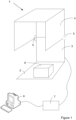
- Figure 1 shows an exemplary RFID tag reading station including an enclosure 1 comprising a reflective base sheet 2 connected to an antenna 3 with a hood 4 pivotally mounted to the antenna 3 by hinges 5.
- the hood 4 may be formed conductive or non-conductive sheets reflective to RF radiation produced by antenna 3.
- Conductive metal sheets, metal mesh or metal foils, such as aluminum, copper, tin, brass, steel, etc. may be used.
- non-conductive but RF reflective sheets such as mylar, metallized plastics, etc.
- Both conductive and non-conductive sheets can be attached to a protective fabric or plastic or foam can be used to enhance the hood's durability.
- the distance between sides of the hood may preferably be between one to three wavelengths (at the frequency of operation of the antenna 3) and more preferably about two wavelengths for reasons described below.
- a box 6 containing items having associated RFID tags may be placed on base 2 and the hood 4 rotated about hinges 5 to close enclose the (as shown in Figure 2 ).
- a reader 7 may then drive antenna 3 so that the tags may be read and supply the read tag data to a computing or storage device, shown by an exemplary computer 8 in this case. Whilst only reading is referred to in this example it is to be appreciated that the tags may also be written to.
- the reader 7 may be incorporated into antenna 3. Reader 7 may require a sensor to indicate that the enclosure is closed before the antenna 3 is driven.
- the enclosure design allows easy placement and removal of items to be read (in the open Figure 1 configuration) as access is provided from a plurality of sides, in this case three, unlike designs allowing access from only one side.
- the hinges 5 may include a locking mechanism or be sprung so that the hood remains supported in the elevated position when raised.
- hood 4 Whilst this is a very effective design there are a range of alternative designs that could be employed.
- One alternative enclosure design would allow hood 4 to be vertically raised and lowered, for example on vertical guide rails.
- hood 4 could rotate about a vertical axis, for example a semi-cylindrical hood rotating with respect to base 2 and antenna 3.
- These designs could all be automated, for example using a geared motor to move the hood between open and closed configurations.
- the hood could be any of a range of shapes including a partial cuboid, other partial polyhedron, partial ellipsoid or partial tetrahedral.
- FIG 3 shows an example antenna 9 suitable for use in the above example RFID tag reading station but also in other applications. Whilst an example patch antenna configuration is shown in Figure 3 it will be apparent from the description below that other configurations may be employed using all or part of the design.
- An antenna is said to be vertically polarised (linear) when its electric field (antenna beam) is perpendicular to the Earth's surface.
- Horizontally polarised (linear) antennas have their electric field (antenna beam) parallel to the Earth's surface.
- Antenna beams at other angles are referred to as having slant polarisation (i.e. between vertical and horizontal).
- near field radiation may have different polarisations to far field radiation where all components have combined.
- Antenna beams may also be tilted within a plane of polarisation at an angle to a normal direction of propagation (i.e. perpendicular to a panel antenna).
- the example antenna shown in Figure 3 includes sixteen radiating elements in the form of patches 10a to 10p arranged in a rectangular array. This is a non-limiting example and other numbers and arrangements of radiating elements may be employed.
- Four feeds are provided in this example which are arranged to drive the antenna so as to produce beams having different polarisations but other numbers of feeds can be employed.
- Beam tilt can be achieved by adjusting delay lines between antennas in a driven group. It will be appreciated that the number of beam polarisations employed and the tilt of each beam may be selected for a particular application. It will also be appreciated that different feed network topologies may be employed using different serial or parallel feed configurations.
- a first feed 11 drives the bases of patches 10j and 10k with delay lines 12 and 13 feeding patches 10f and 10g so as to drive these patches with vertical polarisation as illustrated by the arrows in Figure 4 .
- a third feed 16 drives the left side of patch 10m which in turn drives patches 10i and 10e via delay lines 17 and 18 so as to drive these patches with horizontal polarisation as illustrated by the arrows in Figure 6 .
- Third feed 16 also drives the right side of patch 10c which in turn drives patches 10b and 10a via delay lines 19 and 20 so as to drive these patches with horizontal polarisation as illustrated by the arrows in Figure 6 .
- Third feed 16 also drives the lower side of patch 10n which in turn drives patches 10o and 10p via delay lines 21 and 22 so as to drive these patches with vertical polarisation as illustrated by the arrows in Figure 6 .
- Third feed 16 also drives the upper side of patch 10d which in turn drives patches 10h and 10l via delay lines 23 and 24 so as to drive these patches with vertical polarisation as illustrated by the arrows in Figure 6 .
- a fourth feed 25 drives the bottom of patch 10m which in turn drives patches 10i and 10e via delay lines 26 and 27 so as to drive these patches with vertical polarisation as illustrated by the arrows in Figure 7 .
- Fourth feed 25 also drives the top side of patch 10c which in turn drives patches 10b and 10a via delay lines 28 and 29 so as to drive these patches with vertical polarisation as illustrated by the arrows in Figure 7 .
- Fourth feed 25 also drives the left side of patch 10n which in turn drives patches 10o and 10p via delay lines 30 and 31 so as to drive these patches with horizontal polarisation as illustrated by the arrows in Figure 7 .
- Fourth feed 25 also drives the right side of patch 10d which in turn drives patches 10h and 10l via delay lines 32 and 33 so as to drive these patches with vertical polarisation as illustrated by the arrows in Figure 7 .
- first L shaped group of patches is driven with vertical polarisation and a second L shaped group of patches is driven with horizontal polarisation.
- the far field beam produced by the first and second groups can be designed to have a slant of between 15° to 45 ° with respect to vertical, preferably between 35° to 45° or another value in other applications.
- the propagated antenna beam may also be tilted by adjusting the delays between patches. In the present example the beam can be tilted down by about 15° to 25°, preferably about 20°.
- the first and second L shaped groups in Figures 6 and 7 are asymmetric and the shape may be changed to alter the degree of slant of the polarisation of the far field propagated by each group of adiating elements. It will be appreciated that different degrees of slant and down tilt may be selected depending upon the specific application.
- patch antenna Whilst a patch antenna has been described in the example above it will be appreciated that different type of antennas and radiating elements may be employed, for example slot antennas could be used.
- the patch antenna may be manufactured in a variety of ways although the method disclosed in the applicant's patent US8604981 is one preferred method.
- a package 6 containing items with RFID tags attached may be placed on base 2. There may be hundreds of RFID tags within package 6 disposed in a wide range of orientations. Hood 4 may then be lowered to the position shown in Figure 2 so that the RF reflective material of hood 4 will reflect radiation generated by panel antenna 3.
- Reader 7 in this example has 4 ports which drive the four feeds 11, 12, 16 and 25.
- the four ports are driven sequentially so as to produce beams having vertical polarisation, horizontal polarisation and two different slant polarisations (one positive and one negative in this example).
- One or more beams may also be tilted (down tilt in this case, although it could be in either direction depending upon configuration and the shape of the hood).
- the beams produced by the L shaped groups of radiating elements form over the near field (about one wavelength) and the transition zone (between one to two wavelengths) to form a far field beam based on the components of all radiating elements.
- This means that an RFID tag in the near field will experience a beam polarisation that is strongly based on the polarisation of one or more local radiating elements whereas closer to the far field the components will combine so that the composite beam reflects a polarisation due to the combination of all elements.
- the sequential switching on and off of the reader ports creates an antenna beam pattern that changes during energization and de-energisation phases which enhances RFID tag coupling.
- a large number of RFID tags arranged with different orientations may be reliably read as at least one beam will have sufficient coupling with an RFID tag to provide a successful read.
- these specific polarisations need not be employed and a range of polarisations disposed at sufficient angles to each other may provide effective tag reading.
- three polarisations Data read by antenna 3 and reader 7 may be supplied to a computer 8 or other data processing equipment.
- the present disclosure provides examples of an RFID reading station that is simple, compact, light (about 10Kg) and inexpensive whilst providing high read accuracy at a high read rate (1000 tags per second has been achieved).
- the antenna provides an even near-field energy distribution (due to 16 patches in a small footprint) that can read different types of assets (liquids, metals, plastic, wood, paper, etc.).
- assets liquids, metals, plastic, wood, paper, etc.
- Antenna diversity also ensures reliable RFID tag reading and writing as even if one group of radiating elements is obscured (by metal for example) others may not be.
- the antenna design may be used advantageously in the present application it will be appreciated that example designs and variants applying the principles described may be employed in a wide range of fields.
Landscapes
- Engineering & Computer Science (AREA)
- Physics & Mathematics (AREA)
- Health & Medical Sciences (AREA)
- Toxicology (AREA)
- General Health & Medical Sciences (AREA)
- Electromagnetism (AREA)
- Computer Networks & Wireless Communication (AREA)
- Artificial Intelligence (AREA)
- Computer Vision & Pattern Recognition (AREA)
- General Physics & Mathematics (AREA)
- Theoretical Computer Science (AREA)
- Variable-Direction Aerials And Aerial Arrays (AREA)
- Aerials With Secondary Devices (AREA)
- Waveguide Aerials (AREA)
Claims (15)
- Gehäuse (1) für ein RFID-Lesegerät (7), aufweisend:a. eine Basis (2) mit einer RFID-Antenne (3), die ein Array von Strahlungselementen (10a bis 10p) mit Phasenverzögerungen (12 bis 15, 17 bis 24, 26 bis 33) zwischen Strahlungselementen und mehrere Zuführungen (11, 12, 16, 25) zu dem Antennen-Array aufweist, das so konfiguriert sind, dass die Antenne bei Ansteuerung geneigte Strahlen unterschiedlicher Polarisation erzeugt; undb. eine Haube (4) mit einer für HF-Strahlung reflektierenden Oberfläche, die zwischen folgenden Positionen bewegbar ist:i. einer ersten Position, in der die Haube (4) und die Basis (2) ein abzutastendes Volumen umschließen; undii. einer zweiten Position, in der das Volumen von mehreren Seiten zugänglich ist, um ein Platzieren oder Entnehmen von abzutastenden Gegenständen aus dem Volumen zu erleichtern.
- Gehäuse nach Anspruch 1, wobei die gleichen Strahlungselemente der RFID-Antenne (3) zwei Strahlen erzeugen.
- Gehäuse nach Anspruch 1 oder 2, wobei das Array von Strahlungselementen (10a bis 10p) der RFID-Antenne (3) ein regelmäßiges Array ist.
- Gehäuse nach einem der vorhergehenden Ansprüche, wobei Phasenverzögerungen durch Speiseelemente (12 bis 15, 17 bis 24, 26 bis 33) zwischen benachbarten Strahlungselementen (10a bis 10p) der RFID-Antenne (3) bereitgestellt werden.
- Gehäuse nach Anspruch 4, wobei Phasenverzögerungen zwischen obersten und untersten Strahlungselementen der RFID-Antenne (3) bereitgestellt werden, um eine vertikale Strahlpolarisation zu erzeugen.
- Gehäuse nach Anspruch 4 oder 5, wobei Phasenverzögerungen zwischen am weitesten links und rechts liegenden Strahlungselementen der RFID-Antenne (3) bereitgestellt werden, um eine horizontale Strahlpolarisation zu erzeugen.
- Gehäuse nach einem der Ansprüche 3 bis 6, wobei vier Strahlungselemente (10f, 10g, 10j, 10k) der RFID-Antenne (3) in einem regelmäßigen quadratischen Array angeordnet sind.
- Gehäuse nach einem der vorhergehenden Ansprüche, wobei die Strahlungselemente der RFID-Antenne (3) Patch-Antennen (10a bis 10p) sind.
- Gehäuse nach einem der Ansprüche 1 bis 8, wobei das Volumen von drei oder mehr Seiten aus zugänglich ist.
- Gehäuse nach einem der Ansprüche 1 bis 8, wobei das Volumen von der Vorderseite und von der linken und rechten Seite zugänglich ist.
- Gehäuse nach einem der vorhergehenden Ansprüche, wobei die Haube (4) zwischen der ersten und der zweiten Position rotiert.
- Gehäuse nach einem der vorhergehenden Ansprüche, wobei sich die Haube (4) anhebt, während sie zwischen der ersten und der zweiten Position rotiert.
- Gehäuse nach einem der vorhergehenden Ansprüche, wobei der Abstand zwischen der Antenne (3) und der Haube (4) zwischen dem 1- bis 3-fachen der Wellenlänge für die Betriebsfrequenz der Antenne liegt.
- Gehäuse nach einem der vorhergehenden Ansprüche, wobei die Basis (2) eine reflektierende Basisfolie aufweist, die für HF-Strahlung reflektierend ist.
- Gehäuse nach Anspruch 14, wobei sich die Antenne (3) von der reflektierenden Basisfolie nach oben erstreckt.
Applications Claiming Priority (1)
| Application Number | Priority Date | Filing Date | Title |
|---|---|---|---|
| PCT/NZ2021/050033 WO2022186703A1 (en) | 2021-03-02 | 2021-03-02 | An rfid antenna and an rfid reader enclosure and system |
Publications (5)
| Publication Number | Publication Date |
|---|---|
| EP4302229A1 EP4302229A1 (de) | 2024-01-10 |
| EP4302229A4 EP4302229A4 (de) | 2024-04-03 |
| EP4302229B1 true EP4302229B1 (de) | 2025-03-26 |
| EP4302229C0 EP4302229C0 (de) | 2025-03-26 |
| EP4302229B8 EP4302229B8 (de) | 2025-04-30 |
Family
ID=83154381
Family Applications (1)
| Application Number | Title | Priority Date | Filing Date |
|---|---|---|---|
| EP21929327.1A Active EP4302229B8 (de) | 2021-03-02 | 2021-03-02 | Rfid-antenne und rfid-lesegehäuse und -system |
Country Status (3)
| Country | Link |
|---|---|
| US (1) | US12645897B2 (de) |
| EP (1) | EP4302229B8 (de) |
| WO (1) | WO2022186703A1 (de) |
Family Cites Families (10)
| Publication number | Priority date | Publication date | Assignee | Title |
|---|---|---|---|---|
| US20070279286A1 (en) * | 2006-06-05 | 2007-12-06 | Mark Iv Industries Corp. | Multi-Mode Antenna Array |
| EP2171797A4 (de) | 2007-07-18 | 2014-07-09 | Times 7 Holdings Ltd | Panelantenne und verfahren zur herstellung einer panelantenne |
| CN201528054U (zh) * | 2009-09-29 | 2010-07-14 | 寰波科技股份有限公司 | 三极化阵列天线 |
| US10629999B2 (en) | 2012-03-12 | 2020-04-21 | John Howard | Method and apparatus that isolate polarizations in phased array and dish feed antennas |
| CN203415691U (zh) * | 2013-09-06 | 2014-01-29 | 咏业科技股份有限公司 | 阵列天线 |
| US9929886B2 (en) | 2016-06-06 | 2018-03-27 | Intel Corporation | Phased array antenna cell with adaptive quad polarization |
| JP2017228140A (ja) * | 2016-06-23 | 2017-12-28 | 東芝テック株式会社 | 読取装置及びプログラム |
| JP6936087B2 (ja) * | 2017-09-08 | 2021-09-15 | 東芝テック株式会社 | 読取装置およびプログラム |
| DE102018211931B4 (de) | 2018-07-18 | 2025-12-31 | Fraunhofer-Gesellschaft zur Förderung der angewandten Forschung e.V. | Vorrichtung zur Modenverwirbelung |
| WO2020218927A1 (en) | 2019-04-26 | 2020-10-29 | Vasant Limited | Artificial dielectric material and focusing lenses made of it |
-
2021
- 2021-03-02 EP EP21929327.1A patent/EP4302229B8/de active Active
- 2021-03-02 WO PCT/NZ2021/050033 patent/WO2022186703A1/en not_active Ceased
- 2021-03-02 US US18/548,040 patent/US12645897B2/en active Active
Also Published As
| Publication number | Publication date |
|---|---|
| EP4302229A1 (de) | 2024-01-10 |
| EP4302229C0 (de) | 2025-03-26 |
| WO2022186703A1 (en) | 2022-09-09 |
| EP4302229B8 (de) | 2025-04-30 |
| US12645897B2 (en) | 2026-06-02 |
| EP4302229A4 (de) | 2024-04-03 |
| US20240135120A1 (en) | 2024-04-25 |
| US20240232551A9 (en) | 2024-07-11 |
Similar Documents
| Publication | Publication Date | Title |
|---|---|---|
| EP3276743B1 (de) | Bewegliche antenne und inspektionsvorrichtung | |
| TWI407633B (zh) | 射頻辨識貨架天線系統 | |
| EP2328108B1 (de) | Frequenzselektive oberfläche zur unterstützung des betriebs eines rfid systems | |
| US8299927B2 (en) | Electromagnetic radiation decoupler | |
| JP4841659B2 (ja) | アンテナ装置 | |
| US20080100527A1 (en) | Antenna arrangement | |
| Lehto et al. | Passive UHF RFID in paper industry: Challenges, benefits and the application environment | |
| WO2009086212A1 (en) | Object direction indication through the use of multiple antenna beams | |
| KR101142204B1 (ko) | 근역장 rfid를 이용한 물품관리 시스템 | |
| US20240135120A1 (en) | An rfid antenna and an rfid reader enclosure and system | |
| JP2011180912A (ja) | 無線タグ読取装置及び無線タグ読取方法 | |
| US20100073141A1 (en) | Ic tag reading device | |
| JP2007004810A (ja) | 無線タグ読取り装置 | |
| Li et al. | Two‐dimensional scanning antenna array for UHF radio frequency identification system application | |
| ES2611738T3 (es) | Antenas de parche que incorporan un módulo precableado para mobiliario | |
| Yu et al. | Balanced RFID tag antenna mountable on metallic plates | |
| CN203117999U (zh) | 智能型书柜辨识系统 | |
| JP4417930B2 (ja) | 無線タグ読取装置及び読取方法 | |
| US7801491B2 (en) | Wireless communication system and method | |
| Lee et al. | Extensible compact 8‐port MIMO antenna with pattern gain | |
| US8098139B2 (en) | Test head device | |
| Diugwu et al. | Field distributions and RFID reading within metallic roll cages | |
| JP4882500B2 (ja) | Rfidアンテナ設置台 | |
| CN115392280B (zh) | 一种基于混响理论提高电子标签识别率的方法及系统 | |
| JP2001052123A (ja) | データ読取装置 |
Legal Events
| Date | Code | Title | Description |
|---|---|---|---|
| STAA | Information on the status of an ep patent application or granted ep patent |
Free format text: STATUS: THE INTERNATIONAL PUBLICATION HAS BEEN MADE |
|
| PUAI | Public reference made under article 153(3) epc to a published international application that has entered the european phase |
Free format text: ORIGINAL CODE: 0009012 |
|
| STAA | Information on the status of an ep patent application or granted ep patent |
Free format text: STATUS: REQUEST FOR EXAMINATION WAS MADE |
|
| 17P | Request for examination filed |
Effective date: 20230718 |
|
| AK | Designated contracting states |
Kind code of ref document: A1 Designated state(s): AL AT BE BG CH CY CZ DE DK EE ES FI FR GB GR HR HU IE IS IT LI LT LU LV MC MK MT NL NO PL PT RO RS SE SI SK SM TR |
|
| REG | Reference to a national code |
Ref country code: DE Ref legal event code: R079 Ipc: H01Q0021060000 Ref country code: DE Ref legal event code: R079 Ref document number: 602021028328 Country of ref document: DE Free format text: PREVIOUS MAIN CLASS: G06K0007000000 Ipc: H01Q0021060000 |
|
| A4 | Supplementary search report drawn up and despatched |
Effective date: 20240304 |
|
| RIC1 | Information provided on ipc code assigned before grant |
Ipc: G06K 7/10 20060101ALI20240227BHEP Ipc: H01Q 25/00 20060101ALI20240227BHEP Ipc: H01Q 1/22 20060101ALI20240227BHEP Ipc: H01Q 21/28 20060101ALI20240227BHEP Ipc: H01Q 21/24 20060101ALI20240227BHEP Ipc: H01Q 21/06 20060101AFI20240227BHEP |
|
| DAV | Request for validation of the european patent (deleted) | ||
| DAX | Request for extension of the european patent (deleted) | ||
| GRAP | Despatch of communication of intention to grant a patent |
Free format text: ORIGINAL CODE: EPIDOSNIGR1 |
|
| STAA | Information on the status of an ep patent application or granted ep patent |
Free format text: STATUS: GRANT OF PATENT IS INTENDED |
|
| RIC1 | Information provided on ipc code assigned before grant |
Ipc: G06K 7/10 20060101ALI20241203BHEP Ipc: H01Q 25/00 20060101ALI20241203BHEP Ipc: H01Q 1/22 20060101ALI20241203BHEP Ipc: H01Q 21/28 20060101ALI20241203BHEP Ipc: H01Q 21/24 20060101ALI20241203BHEP Ipc: H01Q 21/06 20060101AFI20241203BHEP |
|
| INTG | Intention to grant announced |
Effective date: 20241213 |
|
| GRAS | Grant fee paid |
Free format text: ORIGINAL CODE: EPIDOSNIGR3 |
|
| GRAA | (expected) grant |
Free format text: ORIGINAL CODE: 0009210 |
|
| STAA | Information on the status of an ep patent application or granted ep patent |
Free format text: STATUS: THE PATENT HAS BEEN GRANTED |
|
| AK | Designated contracting states |
Kind code of ref document: B1 Designated state(s): AL AT BE BG CH CY CZ DE DK EE ES FI FR GB GR HR HU IE IS IT LI LT LU LV MC MK MT NL NO PL PT RO RS SE SI SK SM TR |
|
| REG | Reference to a national code |
Ref country code: GB Ref legal event code: FG4D |
|
| REG | Reference to a national code |
Ref country code: CH Ref legal event code: EP |
|
| REG | Reference to a national code |
Ref country code: DE Ref legal event code: R081 Ref document number: 602021028328 Country of ref document: DE Owner name: TIMES-7 RESEARCH LTD., PETONE, NZ Free format text: FORMER OWNER: TIMES-7 RESEARCH LTD., ALICETOWN, LOWER HUTT, NZ |
|
| REG | Reference to a national code |
Ref country code: CH Ref legal event code: PK Free format text: BERICHTIGUNG B8 |
|
| REG | Reference to a national code |
Ref country code: DE Ref legal event code: R096 Ref document number: 602021028328 Country of ref document: DE |
|
| REG | Reference to a national code |
Ref country code: IE Ref legal event code: FG4D |
|
| RAP4 | Party data changed (patent owner data changed or rights of a patent transferred) |
Owner name: TIMES-7 RESEARCH LIMITED |
|
| U01 | Request for unitary effect filed |
Effective date: 20250423 |
|
| U07 | Unitary effect registered |
Designated state(s): AT BE BG DE DK EE FI FR IT LT LU LV MT NL PT RO SE SI Effective date: 20250429 |
|
| PG25 | Lapsed in a contracting state [announced via postgrant information from national office to epo] |
Ref country code: RS Free format text: LAPSE BECAUSE OF FAILURE TO SUBMIT A TRANSLATION OF THE DESCRIPTION OR TO PAY THE FEE WITHIN THE PRESCRIBED TIME-LIMIT Effective date: 20250626 |
|
| PG25 | Lapsed in a contracting state [announced via postgrant information from national office to epo] |
Ref country code: NO Free format text: LAPSE BECAUSE OF FAILURE TO SUBMIT A TRANSLATION OF THE DESCRIPTION OR TO PAY THE FEE WITHIN THE PRESCRIBED TIME-LIMIT Effective date: 20250626 |
|
| PG25 | Lapsed in a contracting state [announced via postgrant information from national office to epo] |
Ref country code: HR Free format text: LAPSE BECAUSE OF FAILURE TO SUBMIT A TRANSLATION OF THE DESCRIPTION OR TO PAY THE FEE WITHIN THE PRESCRIBED TIME-LIMIT Effective date: 20250326 |
|
| PG25 | Lapsed in a contracting state [announced via postgrant information from national office to epo] |
Ref country code: GR Free format text: LAPSE BECAUSE OF FAILURE TO SUBMIT A TRANSLATION OF THE DESCRIPTION OR TO PAY THE FEE WITHIN THE PRESCRIBED TIME-LIMIT Effective date: 20250627 |
|
| PG25 | Lapsed in a contracting state [announced via postgrant information from national office to epo] |
Ref country code: SM Free format text: LAPSE BECAUSE OF FAILURE TO SUBMIT A TRANSLATION OF THE DESCRIPTION OR TO PAY THE FEE WITHIN THE PRESCRIBED TIME-LIMIT Effective date: 20250326 |
|
| PG25 | Lapsed in a contracting state [announced via postgrant information from national office to epo] |
Ref country code: ES Free format text: LAPSE BECAUSE OF FAILURE TO SUBMIT A TRANSLATION OF THE DESCRIPTION OR TO PAY THE FEE WITHIN THE PRESCRIBED TIME-LIMIT Effective date: 20250326 |
|
| PG25 | Lapsed in a contracting state [announced via postgrant information from national office to epo] |
Ref country code: PL Free format text: LAPSE BECAUSE OF FAILURE TO SUBMIT A TRANSLATION OF THE DESCRIPTION OR TO PAY THE FEE WITHIN THE PRESCRIBED TIME-LIMIT Effective date: 20250326 |
|
| PG25 | Lapsed in a contracting state [announced via postgrant information from national office to epo] |
Ref country code: SK Free format text: LAPSE BECAUSE OF FAILURE TO SUBMIT A TRANSLATION OF THE DESCRIPTION OR TO PAY THE FEE WITHIN THE PRESCRIBED TIME-LIMIT Effective date: 20250326 |
|
| PG25 | Lapsed in a contracting state [announced via postgrant information from national office to epo] |
Ref country code: IS Free format text: LAPSE BECAUSE OF FAILURE TO SUBMIT A TRANSLATION OF THE DESCRIPTION OR TO PAY THE FEE WITHIN THE PRESCRIBED TIME-LIMIT Effective date: 20250726 |
|
| PG25 | Lapsed in a contracting state [announced via postgrant information from national office to epo] |
Ref country code: CZ Free format text: LAPSE BECAUSE OF FAILURE TO SUBMIT A TRANSLATION OF THE DESCRIPTION OR TO PAY THE FEE WITHIN THE PRESCRIBED TIME-LIMIT Effective date: 20250326 |
|
| PLBE | No opposition filed within time limit |
Free format text: ORIGINAL CODE: 0009261 |
|
| STAA | Information on the status of an ep patent application or granted ep patent |
Free format text: STATUS: NO OPPOSITION FILED WITHIN TIME LIMIT |
|
| REG | Reference to a national code |
Ref country code: CH Ref legal event code: L10 Free format text: ST27 STATUS EVENT CODE: U-0-0-L10-L00 (AS PROVIDED BY THE NATIONAL OFFICE) Effective date: 20260211 |
|
| 26N | No opposition filed |
Effective date: 20260105 |
|
| PGFP | Annual fee paid to national office [announced via postgrant information from national office to epo] |
Ref country code: GB Payment date: 20260217 Year of fee payment: 6 |
|
| U20 | Renewal fee for the european patent with unitary effect paid |
Year of fee payment: 6 Effective date: 20260326 |