EP4302011B1 - Leuchte - Google Patents
Leuchte Download PDFInfo
- Publication number
- EP4302011B1 EP4302011B1 EP22705480.6A EP22705480A EP4302011B1 EP 4302011 B1 EP4302011 B1 EP 4302011B1 EP 22705480 A EP22705480 A EP 22705480A EP 4302011 B1 EP4302011 B1 EP 4302011B1
- Authority
- EP
- European Patent Office
- Prior art keywords
- solid
- state light
- array
- light sources
- lamp
- Prior art date
- Legal status (The legal status is an assumption and is not a legal conclusion. Google has not performed a legal analysis and makes no representation as to the accuracy of the status listed.)
- Active
Links
Images


Classifications
-
- F—MECHANICAL ENGINEERING; LIGHTING; HEATING; WEAPONS; BLASTING
- F21—LIGHTING
- F21K—NON-ELECTRIC LIGHT SOURCES USING LUMINESCENCE; LIGHT SOURCES USING ELECTROCHEMILUMINESCENCE; LIGHT SOURCES USING CHARGES OF COMBUSTIBLE MATERIAL; LIGHT SOURCES USING SEMICONDUCTOR DEVICES AS LIGHT-GENERATING ELEMENTS; LIGHT SOURCES NOT OTHERWISE PROVIDED FOR
- F21K9/00—Light sources using semiconductor devices as light-generating elements, e.g. using light-emitting diodes [LED] or lasers
- F21K9/20—Light sources comprising attachment means
- F21K9/23—Retrofit light sources for lighting devices with a single fitting for each light source, e.g. for substitution of incandescent lamps with bayonet or threaded fittings
-
- F—MECHANICAL ENGINEERING; LIGHTING; HEATING; WEAPONS; BLASTING
- F21—LIGHTING
- F21K—NON-ELECTRIC LIGHT SOURCES USING LUMINESCENCE; LIGHT SOURCES USING ELECTROCHEMILUMINESCENCE; LIGHT SOURCES USING CHARGES OF COMBUSTIBLE MATERIAL; LIGHT SOURCES USING SEMICONDUCTOR DEVICES AS LIGHT-GENERATING ELEMENTS; LIGHT SOURCES NOT OTHERWISE PROVIDED FOR
- F21K9/00—Light sources using semiconductor devices as light-generating elements, e.g. using light-emitting diodes [LED] or lasers
- F21K9/60—Optical arrangements integrated in the light source, e.g. for improving the colour rendering index or the light extraction
-
- F—MECHANICAL ENGINEERING; LIGHTING; HEATING; WEAPONS; BLASTING
- F21—LIGHTING
- F21S—NON-PORTABLE LIGHTING DEVICES; SYSTEMS THEREOF; VEHICLE LIGHTING DEVICES SPECIALLY ADAPTED FOR VEHICLE EXTERIORS
- F21S41/00—Illuminating devices specially adapted for vehicle exteriors, e.g. headlamps
- F21S41/10—Illuminating devices specially adapted for vehicle exteriors, e.g. headlamps characterised by the light source
- F21S41/14—Illuminating devices specially adapted for vehicle exteriors, e.g. headlamps characterised by the light source characterised by the type of light source
- F21S41/141—Light emitting diodes [LED]
- F21S41/151—Light emitting diodes [LED] arranged in one or more lines
-
- F—MECHANICAL ENGINEERING; LIGHTING; HEATING; WEAPONS; BLASTING
- F21—LIGHTING
- F21S—NON-PORTABLE LIGHTING DEVICES; SYSTEMS THEREOF; VEHICLE LIGHTING DEVICES SPECIALLY ADAPTED FOR VEHICLE EXTERIORS
- F21S41/00—Illuminating devices specially adapted for vehicle exteriors, e.g. headlamps
- F21S41/60—Illuminating devices specially adapted for vehicle exteriors, e.g. headlamps characterised by a variable light distribution
- F21S41/65—Illuminating devices specially adapted for vehicle exteriors, e.g. headlamps characterised by a variable light distribution by acting on light sources
- F21S41/663—Illuminating devices specially adapted for vehicle exteriors, e.g. headlamps characterised by a variable light distribution by acting on light sources by switching light sources
-
- F—MECHANICAL ENGINEERING; LIGHTING; HEATING; WEAPONS; BLASTING
- F21—LIGHTING
- F21W—INDEXING SCHEME ASSOCIATED WITH SUBCLASSES F21K, F21L, F21S and F21V, RELATING TO USES OR APPLICATIONS OF LIGHTING DEVICES OR SYSTEMS
- F21W2102/00—Exterior vehicle lighting devices for illuminating purposes
- F21W2102/10—Arrangement or contour of the emitted light
- F21W2102/13—Arrangement or contour of the emitted light for high-beam region or low-beam region
-
- F—MECHANICAL ENGINEERING; LIGHTING; HEATING; WEAPONS; BLASTING
- F21—LIGHTING
- F21Y—INDEXING SCHEME ASSOCIATED WITH SUBCLASSES F21K, F21L, F21S and F21V, RELATING TO THE FORM OR THE KIND OF THE LIGHT SOURCES OR OF THE COLOUR OF THE LIGHT EMITTED
- F21Y2105/00—Planar light sources
- F21Y2105/10—Planar light sources comprising a two-dimensional array of point-like light-generating elements
- F21Y2105/12—Planar light sources comprising a two-dimensional array of point-like light-generating elements characterised by the geometrical disposition of the light-generating elements, e.g. arranging light-generating elements in differing patterns or densities
-
- F—MECHANICAL ENGINEERING; LIGHTING; HEATING; WEAPONS; BLASTING
- F21—LIGHTING
- F21Y—INDEXING SCHEME ASSOCIATED WITH SUBCLASSES F21K, F21L, F21S and F21V, RELATING TO THE FORM OR THE KIND OF THE LIGHT SOURCES OR OF THE COLOUR OF THE LIGHT EMITTED
- F21Y2107/00—Light sources with three-dimensionally disposed light-generating elements
- F21Y2107/90—Light sources with three-dimensionally disposed light-generating elements on two opposite sides of supports or substrates
-
- F—MECHANICAL ENGINEERING; LIGHTING; HEATING; WEAPONS; BLASTING
- F21—LIGHTING
- F21Y—INDEXING SCHEME ASSOCIATED WITH SUBCLASSES F21K, F21L, F21S and F21V, RELATING TO THE FORM OR THE KIND OF THE LIGHT SOURCES OR OF THE COLOUR OF THE LIGHT EMITTED
- F21Y2115/00—Light-generating elements of semiconductor light sources
- F21Y2115/10—Light-emitting diodes [LED]
Definitions
- the present description relates to lamps.
- One or more embodiments may be applied to lamps employing solid-state light sources, e.g., LED sources.
- One or more embodiments may be advantageously employed in the automotive sector, for example as automotive retrofit lamps for motor vehicles.
- light sources such as LED sources may offer various advantages compared to conventional lamps or bulbs.
- LED sources are brighter, quicker on power up and may easily be PWM modulated in order to adjust the intensity of the emitted light.
- LED chips may be operated in array, in parallel or in mixed configurations, and exhibit a rather long-time durable life.
- LED lamps which may be employed instead of conventional lamps, e.g., instead of halogen lamps, while being adapted to comply with specifications.
- the US Patent Application published as US2010/0213809 (Roehl ) describes a lamp having a closed cap, wherein the light emission is provided by one ore more semiconductor light sources and the output flux is predetermined by the distance and the position of the (LED) sources with respect to the reference plane of the cap.
- Documents CN 205606398 U and WO 2018/162341 A1 describe similar solutions. Also documents KR 2016 0101380 A , TW M 498 688 U , and US 2029/184891 A1 provide information on the general state of the art in that area.
- EP 3 839 322 A1 describes an H7 retrofit lamp for low-beam applications which favours compliance with ECE R112 Regulation, by having the light distribution coming from two opposite linear LED arrays or clusters operate in two different modes: by providing either direct light, if this is desired for safety reasons, or indirect/reflected light for the points above cut-off, which illuminates road panels.
- the H-type retrofit solutions normally envisage the presence of LED arrays or clusters arranged linearly, so as to mimic the light emission surface of a filament lamp.
- Figure 1 is a side elevation view of a solid-state H4 retrofit lamp for motor vehicles, available from the companies of the OSRAM group under the trade name of H4 3.5 (9726CW 14W 12V/24V P43T 4x2 OSRAM).
- Such a lamp comprises a lamp body extending along a reference axis X10 between a proximal base portion 101 and a distal front portion 102.
- the lamp body comprises a (e.g., plate-like) support member 12 having a first and a second mutually opposed sides.
- the second array of solid-state light sources 142 is spaced from the first array of solid-state light sources 141, and energizing the sources of array 142 leads to providing a high-beam.
- the LEDs of arrays 141 and 142 are (6x) Samsung LH181A LEDs, all having the same configuration, with a light emitting area (LEA) of 1.91 ⁇ 1.91 mm.
- Lamp 10 comprises a mounting member 20, adapted to mount lamp 10 onto a vehicle.
- Said mounting member 20 includes, at the rear base portion 101 of the lamp body 10, at least one ring-shaped reference formation 201, which defines a reference plane RP transversely of the reference axis X10.
- the lamp body 10 includes two parts having heatsink properties, enclosing a planar printed circuit board (PCB), the LED arrays 141, 142 being arranged on both opposed sides or faces of the board, so as to emit light in opposite directions, i.e., towards opposed half-spaces.
- PCB printed circuit board
- the two heatsink parts or bodies protect the electronics underneath and help the light emitted by the LEDs to generate a radiation beam within the cut-off angles specified by ECE R112 Regulation.
- the lamp body 10 has, at the LED arrays 141 and 142, windows through which radiation is emitted with a radiation pattern mimicking the near-field distribution of a conventional filament lamp.
- the lamp body is produced by metal (aluminium) moulding.
- a polymeric material may be considered an alternative option.
- the shape of the lamp body controls the distribution of the light coming from the white light emitted by the LEDs with a Lambertian distribution.
- the light distribution is mainly determined by the position of the LED arrays and by the position of the single LEDs within an array.
- the LEDs of both arrays 141 and 142 on each side of the lamp have a linear arrangement: a row of three LEDs aligned in the direction of axis X10 in each array 141, 142, with the two arrays 141, 142 substantially aligned with each other at said axis, in order to mimic (approximate) the light emitting surface of a standard filament source.
- Table I in the following shows some characteristic values of arrays 141 and 142 of the lamp shown in Figure I, which are presented by way of comparison with the corresponding values in a conventional H4 lamp.
- Table I - LED H4 3.5 OSRAM vs. conventional H4 filament lamp Lamp type Conventional H4 H4 3.5 (9726CW 14W 12V/24V P43T 4x2 OSRAM) .
- the distances referring to the LEDs are measured with reference to the light emitting areas (LEA) thereof.
- Point 6.3.3.1 of the Regulation specifies that the intersection point (HV) of lines h h and v v must be located within the isolux of 80% of the maximum light intensity (Imax).
- One or more embodiments aim at contributing to tackle the aspects outlined in the foregoing.
- said object may be achieved thanks to a lamp having the features set forth in the claims that follow.
- One or more embodiments favour achieving compliance with specifications such as ECE R112 Regulation, repeatedly mentioned in the foregoing, e.g., with reference to point 6.3.3.1, i.e., the achievement of high intensity (80% of the maximum light intensity value) on the central point H-V of the pattern.
- One or more embodiments act on the shape of the array or cluster of the sources for a high-beam application.
- One or more embodiments help overcoming the limitations of the known art, being adapted to comply with specifications as regards light intensity for all the points normed in ECE R112 Class B Regulation for high-beam applications.
- One or more embodiments help achieving light intensity values higher than achievable either with standard LED configurations or with halogen lamps, while obtaining a more uniform light distribution as compared to a standard LED configuration.
- reference number 10 generally denotes a lamp which may be employed, for example, for retrofit, or optionally for the initial equipment of a light, e.g. a headlight, such as a low-beam and a high-beam projector of a vehicle such as a motor vehicle, not visible in the Figures.
- a light e.g. a headlight, such as a low-beam and a high-beam projector of a vehicle such as a motor vehicle, not visible in the Figures.
- an automotive lamp 10 as exemplified herein is adapted to be mounted onto a support body P, the profile whereof is schematically indicated in Figure 3 only and which, in the case of use in a (motor) vehicle headlight, may have the features of a projector.
- lamp 10 may include a generally elongated body or housing, extending in the direction of a longitudinal reference axis X10 and having a base rear or proximal end 101 (adapted to be mounted, e.g., inserted, into support body P) and a front (distal) end 102 (from which light radiation is emitted in operation).
- lamp 10 may be mounted on the vehicle, i.e., on the support body P (a projector, for example) so that axis X10 is oriented in a substantially horizontal direction, the light radiation being emitted from the front end 102 and being equally oriented in a substantially horizontal direction, radially, i.e., laterally, to axis X10.
- the lamp body 10 may comprise a support 12 (e.g., a plate-like support, substantially corresponding to a printed circuit board, PCB) having opposed sides or faces, each of which being provided with two solid-state, e.g., LED, light sources which are denoted by references 141 and 142.
- a support 12 e.g., a plate-like support, substantially corresponding to a printed circuit board, PCB
- PCB printed circuit board
- lamp 10 in Figures 2 and following may therefore comprise a lamp body extending along a reference axis X10 between a proximal base portion 101 and a distal front portion 102, the lamp body comprising a (e.g., plate-like) support member 12 having a first and a second mutually opposed sides.
- a (e.g., plate-like) support member 12 having a first and a second mutually opposed sides.
- the second array of solid-state light sources 142 is spaced from the first array of solid-state light sources 141 and, when sources 142 are energized, is adapted to provide a high-beam.
- the LEDs of arrays 141 and 142 may have the same configuration, for example (6x) Luxeon Z ES LEDs having the same configuration, with a light emitting area (LEA) of 1.5 x 1.5 mm.
- (6x) Luxeon Z ES LEDs having the same configuration, with a light emitting area (LEA) of 1.5 x 1.5 mm.
- a mounting member 20 is present which is configured to mount lamp 10 onto a vehicle.
- Said mounting member 20 includes, at the rear base portion 101 of the lamp body, at least a ring-shaped reference formation 201 defining a reference plane RP transversely of reference axis X10.
- the solution shown herein is only one among various possible solutions for mounting lamp 10 on such a support body as a projector P of a motor vehicle lamp, e.g., via connections substantially comprising quarter-turn connections.
- the ring-shaped member 20 illustrated herein generally exemplifies a member configured for mounting the lamp on a vehicle, said member comprising, at the rear part of the lamp body, at least one reference formation (such as a ring-shaped flange 201) adapted to define a reference plane (denoted as RP in Figure 5 ) transversely of longitudinal axis X10.
- both arrays 141 and 142 consist of three LEDs aligned in the direction of axis X10.
- array 142 comprises three LEDs arranged according to a generally L-shaped configuration.
- member 12 may be oriented in a substantially vertical direction, with the LED arrays 141, 142 projecting light radiation in a substantially horizontal direction, starting from the opposed faces of the plate member 12, radially, i.e., laterally to axis X10.
- the light sources e.g., LEDs as described in the foregoing
- the light sources may be arranged on the plate-like member 12 with the interposition of a material having a finish and/or a colour feature (or, in general, optical properties) adapted to enhance the performance of lamp 10.
- a so-called solder mask may exemplify such a material.
- the support member 12 may be arranged between two complementary, e.g., shell-shaped, pieces 161, 162 of moulded (metal or plastics) material.
- member 12 may be sandwiched between the complementary pieces 161, 162, forming an assembly which can be mounted via screws 18 traversing respective holes provided in the pieces 161, 162 and in the plate-like member 12 sandwiched between said pieces.
- the rear end 101 of the lamp body (comprising elements 12, 161 and 162) may have a generally sculptured structure (e.g., a finned structure) having heatsink properties.
- both complementary pieces 161, 162 may be made of a material (e.g., a metal or plastics material) having heat conductive properties: this favours the transfer of heat generated by LED sources 141, 142 towards the rear end 101, contributing to dissipating the heat generated by sources 141, 142 in operation.
- a material e.g., a metal or plastics material
- the rear end 101 of body 10 may be shaped as a sort of box or cage adapted to house electric/electronic circuitry 21 (of a kind known in itself), which are adapted to supply the light sources 141, 142 through electrically conductive lines - not visible in the Figures - which are provided e.g., in the form of printed circuit tracks on member 12.
- the lamp body 10 may have fixation members associated thereto, such as for example a ring-shaped mounting member 20 optionally having a sealing member 202 associated thereto.
- the lamp body 10 may be provided, intermediate ends 101 and 102, and advantageously nearer to front end 102, with two tray-shaped grooves 221, 222.
- said grooves have the approximate shape of a funnel, having bottom apertures which are more clearly visible in the exploded perspective view of Figure 2 .
- grooves 221, 222 originate two mutually opposed recesses, each recess having a respective planar bottom surface given by member 12 carrying the light sources 141, 142 and by the regions of member 12 surrounding the latter, said surface being surrounded by respective peripheral sources.
- the light radiation from sources 141 and 142 is projected from the lamp body 10 (in a generally radial direction with respect to axis X10, and horizontally, considering the possible mounting condition onto a support/projector P exemplified in Figure 3 ) and is adapted to traverse respective light-permeable portions provided at the bottom of the grooves/recesses 221, 222.
- both arrays 141 and 142 consist of three LEDs aligned in the direction of axis X10.
- array 142 therefore, it is possible to distinguish two array ends, which in turn may be defined as rear or proximal end and front or distal end) similarly to what has been stated for ends 101 and 102 of lamp 10.
- the second array of light sources 142 as shown in Figure 2 and following is not optically coupled to shield 150, i.e., it is optically uncoupled from shield 150.
- the second array of solid-state light sources 142 is adapted to provide a light emission power which is higher on the distal side thereof (identified by sources 1420, 1422 of row 146) as compared to the proximal side (identified by source 1421) .
- said first single row 144 i.e., sources 1420 and 1421
- said second single row 146 i.e., sources 1420 and 1422
- a common light source i.e., source 1420
- said first single row 144 i.e., sources 1420 and 1421, extends laterally offset to the reference axis (X10).
- said light source 1420 (which is common and at the corner position in the second array of solid-state light sources 142) is laterally offset to the reference axis X10, and the second single row of sources 146 in the second array of sources 142 comprises a further light source (i.e., source 1422) which is intersected by reference axis X10.
- the solid-state light sources 1420, 1421, 1422 included in the second array 142 may have the same luminous flux.
- the second array of light sources 142 on each side of lamp 10, may comprise no more than three solid-state light sources (i.e., the three LEDs 1420, 1421, 1422), each having a luminous flux of approximately 250-300 lumen [lm].
- the second array of solid-state light sources 142 may consist of a first 1420, a second 1421 and a third 1422 solid-state light source, wherein:
- lamp 10 may include a mounting member 20 configured to mount lamp 10 on a vehicle (projector P in Figure 3 ), such mounting member comprising, at the rear base portion of the lamp body, at least a reference formation (such as ring 201) defining a reference plane RP transversely of reference axis X1.
- a mounting member 20 configured to mount lamp 10 on a vehicle (projector P in Figure 3 ), such mounting member comprising, at the rear base portion of the lamp body, at least a reference formation (such as ring 201) defining a reference plane RP transversely of reference axis X1.
- the second array of solid-state light sources 142 may comprise LEDs, optionally top-emitting LEDs.
- the second array of solid-state light sources 142 may comprise LEDs, optionally top-emitting LEDs, being all LEDs of the same nature.
- said features may be adopted also for the first array of sources 141.
- the second arrays of solid-state light sources 142 (and advantageously also the first arrays 141) on the one and the other opposed sides of support member 12 are arranged mirror-symmetrically on the two sides of support member 12.
- Embodiments as illustrated in Figure 2 and following successfully solve the problem of compliance with ECE R112 Class B Regulation for high-beam applications, also as regards the specifications of point 6.3.3.1, i.e., achieving 80% of the maximum intensity at the H-V (0,0) central point.
- One or more embodiments provide a new shape for array 142 and, advantageously, envisage the use of top-emitting LEDs in order to increase the intensity values.
- Such a back-ray-tracing technique may be applied, for example, to a square-shaped high-beam headlight. Similar results may however be achieved also with other 3D models of headlights, having a circular or rounded shape.
- the back-ray-tracing technique may be seen as a sort of reverse engineering applied on the system consisting of the lamp and the projector.
- the simulation may be performed for the high-beam function by using a simulation tool such as the software available from Synopsys, Inc. of Mountain View, California (USA) under the trade name LucidShape, by switching on only the array 142 which is optically uncoupled with respect to the shield 150.
- a simulation tool such as the software available from Synopsys, Inc. of Mountain View, California (USA) under the trade name LucidShape, by switching on only the array 142 which is optically uncoupled with respect to the shield 150.
- the maximum light intensity of the LED farthest away from shield 150 approximately amounts to 16500 cd, as opposed to the value of 43100 cd generated by the foremost LED in the linear array, i.e., the LED closest to shield 150.
- This solution enables achieving more benefits also from the third LED, by shifting it forward, and by imparting to array 142, for example, an L-shaped configuration.
- array 142 for example, an L-shaped configuration.
- LEDs 1420, 1421 and 1422 are better exploited in terms of light intensity and light distribution on the HV test points.
- LEDs 1420, 1421 and 1422 are so to say “concentrated” near shield 150, which improves the homogeneity of the light distribution, also leading to an increase of the intensity values.
- Such an array is compatible with the mechanical components of a conventional lamp 10 ( Figure 1 ) and with the manufacturing process thereof, as currently employed in the production of the present H4-type retrofit lamp.
- Table III shows, with reference to Figure 4 , some possible features of embodiments. Such features are shown for immediate reference and for a comparison with the features recalled in previous Table I relating to a H4 3.5 OSRAM LED lamp and to a conventional H4 filament lamp.
- Table III - Embodiments Lamp type Present specification Source Luxeon Z ES (6x) - see lumileds.com/ e': distance Lo-Beam array 141/ reference plane RP [mm] 28.5 f': distance (separation) between Lo-Beam 141 and Hi-Beam 142 arrays [mm] 1.7 y 0': distance outer edge of longitudinal row 144 (LEDs 1420, 1421)/ reference axis [mm] 2.25 y_tot': width of Hi-Beam array 142 (length of transversal row 146 - LEDs 1420 and 1422) 3.34 Z_HB': length of Hi-Beam array 142 (length of longitudinal row 144 - LEDs 1420 and 1421) [mm] 3.34
- the radiation pattern generated by lamp 10 is more intense, and the light is distributed more uniformly around the H-V (0,0) point than in the conventional solutions, therefore better approaching the light distribution of a standard filament lamp.
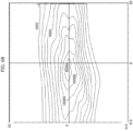
- Figures 5A and 5B show light distributions simulated by using the simulation tool LucidShape available from Synopsis, Inc. (which has already been mentioned in the foregoing).
- the graphs show isocandela lines with respective values expressed in candles (cd) corresponding to 70000, 40000, 16000, 4000 and 1000 cd ( Figure 5A ) and 90000, 40000, 16000, 4000 and 1000 cd ( Figure 5B ).
- Figures 5A and 5B show that the radiation pattern of the L-shaped arrangement ( Figure 5B ) is more uniform and the maximum light intensity (Emax) is higher by 21% (from 75500 cd to 91400 cd).
- Figure 6A shows the light distribution measured for a standard LED configuration (i.e., a linear array, as shown in Figure 1 ) compared to the light distribution detected in an L-shaped array, shown in Figure 6B .
- the measurements were performed on a headlight of a motor vehicle Skoda Fabia, by using measurement software available from EVERFINE Corporation of Hangzou, China.
- the graphs of Figures 6A and 6B show isocandela lines with respective values expressed in candles (cd) corresponding to 63000, 40000, 16000, 4000 and 1000 cd ( Figure 6A ) and 60000, 40000, 16000, 4000 and 1000 cd ( Figure 6B ).
- the graphs in Figures 6A and 6B confirm the improvement of uniformity in the L-shaped radiation pattern ( Figure 6B ), because all LEDs in the array 142 contribute appreciably to the radiation pattern, unlike the case of a linear array, wherein the LED farthest away from shield 150 (and closest to mounting member 20) contributes weakly, with the risk of generating a non-homogeneous lighting configuration.
- one or more embodiments may envisage repositioning the shield 150.
- Table IV shows the results obtained from a simulation of one and the same projector P respectively referring to:
- the maximum intensity (Emax) was increased by approximately 15000 cd, from a standard linear LED array to an L-shaped array, therefore correctly complying with the regulatory specifications.
- One of the advantages of the embodiments is the improvement of the uniformity of the radiation pattern and the increase of the intensity values on the HV test points, in comparison with a standard linear array.
- One or more embodiments favour a more efficient use of the LED emission: by using the same number and the same luminous flux it is possible to obtain a maximum intensity value (Emax) higher than in a conventional linear arrangement (and also higher than in a conventional halogen lamp).
- an automotive solid-state lamp for a vehicle (see for example projector P) comprises a lamp body (e.g., 12, 161, 162, 20) extending along a longitudinal reference axis (e.g., X10) between a proximal base portion (e.g., 101) and a distal front portion (e.g., 102), wherein the lamp body comprises a support member (e.g., 12) having a first and a second opposed sides, wherein each one of the opposed sides of the support member has arranged thereon:
- the second array of solid-state light sources (142) consists of:
- said first single row (e.g., 144) and said second single row (e.g., 146) of solid-state light sources share a single common solid-state light source (e.g., 1420) in the second array of solid-state light sources.
- said single common solid-state light source (e.g., 1420) is at a corner position in the second array of solid-state light sources.
- said single common solid-state light source (e.g., 1420) in the second array of solid-state light sources is laterally offset to said reference axis (e.g., X10) and said second single row in the second array of solid-state light sources comprises a further solid-state light source (e.g., 1422) intersected by said reference axis.
- the second array of solid-state light sources (e.g., 142) is L-shaped.
- the first single row (e.g., 144) of solid-state light sources in the second array of solid-state light sources extends laterally offset to said reference axis.
- the first array of solid-state light sources (e.g., 141) is arranged on the support member in register with (i.e., aligned with) said reference axis (e.g., X10), and said second single row of solid-state light sources in the second array of solid-state light sources comprises a solid-state light source (e.g., 1422) intersected by said reference axis.
- said reference axis e.g., X10
- the solid-state light sources e.g., 1420, 1421, 1422
- the solid-state light sources in the second array of solid-state light sources have the same luminous flux.
- the second array of solid-state light sources consists of three solid-state light sources (e.g., 1420, 1421, 1422).
- the second array of solid-state light sources consists of a first (e.g., 1420), a second (e.g., 1421) and a third (e.g., 1422) solid-state light source, wherein:
- the second array of solid-state light sources consists of solid-state light sources (e.g., 1420, 1421, 1422) each having a luminous flux between about 250 lumen and about 300 lumen.
- the overall (high-beam) luminous flux may therefore amount to 1500 - 1800 lumen.
- the second array of solid-state light sources (e.g., 142; 1420, 1421, 1422) comprises LEDs, optionally top-emitting LEDs.
- the second arrays of solid-state light sources (e.g., 142) on the one and the other of the opposed sides of the support member are arranged mirror-symmetrically on the two sides of the support member.
- Lamp 10 Base portion 101 Front portion 102 Reference axis X10 Support member 12 Array of low-beam light sources 141 Shield 150 Array of high-beam light sources 142 First row of light sources 1420, 1421 Second row of light sources 1420, 1422 Parts 161, 162 Screws 18 Mounting member 20 Mounting member flange 201 Ring 202 Circuitry 21 Projector P Reference plane RP
Landscapes
- Engineering & Computer Science (AREA)
- General Engineering & Computer Science (AREA)
- Physics & Mathematics (AREA)
- Microelectronics & Electronic Packaging (AREA)
- Optics & Photonics (AREA)
- Non-Portable Lighting Devices Or Systems Thereof (AREA)
Claims (15)
- Kraftfahrzeug-Festkörperlampe (10) für ein Fahrzeug, umfassend einen Lampenkörper (12, 161, 162, 20), der sich entlang einer Längsreferenzachse (X10) zwischen einem proximalen Basisabschnitt (101) und einem distalen Vorderabschnitt (102) erstreckt, wobei der Lampenkörper (12, 161, 162, 20) ein Stützelement (12) mit einer ersten und einer zweiten gegenüberliegenden Seite umfasst, wobei auf jeder der gegenüberliegenden Seiten des Stützelements (12) angeordnet ist:eine erste Anordnung von Festkörperlichtquellen (141) mit einer Abschirmung (150), die optisch damit gekoppelt ist und konfiguriert ist, um bei Erregung ein Kraftfahrzeug-Abblendlicht bereitzustellen,eine zweite Anordnung von Festkörperlichtquellen (142), die sich zwischen dem Basisabschnitt (101) und der ersten Anordnung von Festkörperlichtquellen (141) befindet, wobei die zweite Anordnung von Festkörperlichtquellen (142) von der ersten Anordnung von Festkörperlichtquellen (141) beabstandet ist und konfiguriert ist, um bei Erregung ein Kraftfahrzeug-Fernlicht bereitzustellen,dadurch gekennzeichnet, dass
die zweite Anordnung von Festkörperlichtquellen (142) besteht aus:einer ersten einzelnen Reihe (144; 1420, 1421) von Festkörperlichtquellen, die sich in Längsrichtung des Lampenkörpers (12, 161, 162, 20) zwischen einer proximalen Seite (1421) der zweiten Anordnung (142) neben dem proximalen Basisabschnitt (101) und einer distalen Seite (1420) der zweiten Anordnung (142) neben der ersten Anordnung von Festkörperlichtquellen (141) erstreckt, undeiner zweiten einzelnen Reihe (146; 1420, 1422) von Festkörperlichtquellen, die sich quer zum Lampenkörper (12, 161, 162, 20) an der distalen Seite (1420) der zweiten Anordnung (142) neben der ersten Anordnung von Festkörperlichtquellen (141) erstreckt. - Lampe (10) nach Anspruch 1, wobei die erste einzelne Reihe (144) und die zweite einzelne Reihe (146) von Festkörperlichtquellen eine einzelne gemeinsame Festkörperlichtquelle (1420) in der zweiten Anordnung von Festkörperlichtquellen (142) aussparen.
- Lampe (10) nach Anspruch 2, wobei sich die einzelne gemeinsame Festkörperlichtquelle (1420) an einer Eckposition in der zweiten Anordnung von Festkörperlichtquellen (142) befindet.
- Lampe (10) nach Anspruch 2 oder Anspruch 3, wobei die einzelne gemeinsame Festkörperlichtquelle (1420) in der zweiten Anordnung von Festkörperlichtquellen (142) seitlich zur Referenzachse (X10) versetzt ist und die zweite einzelne Reihe (146) in der zweiten Anordnung von Festkörperlichtquellen (142) eine weitere Festkörperlichtquelle (1422) umfasst, die von der Referenzachse (X10) geschnitten wird.
- Lampe (10) nach einem der vorhergehenden Ansprüche, wobei die zweite Anordnung von Festkörperlichtquellen (142) L-förmig ist.
- Lampe (10) nach einem der vorhergehenden Ansprüche, wobei sich die erste einzelne Reihe (144) von Festkörperlichtquellen in der zweiten Anordnung von Festkörperlichtquellen (142) seitlich versetzt zur Referenzachse (X10) erstreckt.
- Lampe (10) nach einem der vorhergehenden Ansprüche, wobei:die Abschirmung (150), die optisch mit der ersten Anordnung von Festkörperlichtquellen (141) gekoppelt ist, eine längliche Abschirmung (150) umfasst, die sich parallel zur Referenzachse (X10) erstreckt, unddie erste einzelne Reihe (144) von Festkörperlichtquellen sich parallel zur Referenzachse (X10) erstreckt, die mit der länglichen Abschirmung (150) ausgerichtet ist.
- Lampe (10) nach einem der vorhergehenden Ansprüche, wobei die erste Anordnung von Festkörperlichtquellen (141) auf dem Stützelement (12) in Ausrichtung mit der Referenzachse (X10) angeordnet ist und die zweite einzelne Reihe (146) von Festkörperlichtquellen in der zweiten Anordnung von Festkörperlichtquellen (142) eine Festkörperlichtquelle (1422) umfasst, die von der Referenzachse (X10) geschnitten wird.
- Lampe (10) nach einem der vorhergehenden Ansprüche, wobei die Festkörperlichtquellen (1420, 1421, 1422) in der zweiten Anordnung von Festkörperlichtquellen (142) einen gleichen Lichtstrom aufweisen.
- Lampe (10) nach einem der vorhergehenden Ansprüche, wobei die zweite Anordnung von Festkörperlichtquellen (142) aus drei Festkörperlichtquellen (1420, 1421, 1422) besteht.
- Lampe (10) nach Anspruch 10, wobei die zweite Anordnung von Festkörperlichtquellen (142) aus einer ersten (1420), einer zweiten (1421) und einer dritten (1422) Festkörperlichtquelle besteht, wobei:die erste Festkörperlichtquelle (1420) und die zweite Festkörperlichtquelle (1421) die erste einzelne Reihe (144; 1420, 1421) von Festkörperlichtquellen bereitstellen, die sich in Längsrichtung des Lampenkörpers (12, 161, 162, 20) erstreckt, unddie erste Festkörperlichtquelle (1420) und die dritte Festkörperlichtquelle (1422) die zweite einzelne Reihe (146) von Festkörperlichtquellen bereitstellen, die sich quer zum Lampenkörper (12, 161, 162, 20) an der distalen Seite (1420) der zweiten Anordnung (142) erstreckt.
- Lampe (10) nach einem der vorhergehenden Ansprüche, wobei die zweite Anordnung von Festkörperlichtquellen (142) aus Festkörperlichtquellen (1420, 1421, 1422) besteht, die jeweils einen Lichtstrom zwischen etwa 250 Lumen und etwa 300 Lumen aufweisen.
- Lampe (10) nach einem der vorhergehenden Ansprüche, wobei die zweite Anordnung von Festkörperlichtquellen (142; 1420, 1421, 1422) LEDs umfasst.
- Lampe (10) nach Anspruch 13, wobei die zweite Anordnung von Festkörperlichtquellen (142; 1420, 1421, 1422) nach oben emittierende LEDs umfasst.
- Lampe (10) nach einem der vorhergehenden Ansprüche, wobei die zweiten Anordnungen von Festkörperlichtquellen (142), die auf der einen und der anderen der gegenüberliegenden Seiten des Stützelements (12) angeordnet sind, spiegelsymmetrisch auf den zwei Seiten des Stützelements (12) angeordnet sind.
Applications Claiming Priority (2)
| Application Number | Priority Date | Filing Date | Title |
|---|---|---|---|
| IT202100004856 | 2021-03-02 | ||
| PCT/IB2022/051329 WO2022185136A1 (en) | 2021-03-02 | 2022-02-15 | Lamp |
Publications (2)
| Publication Number | Publication Date |
|---|---|
| EP4302011A1 EP4302011A1 (de) | 2024-01-10 |
| EP4302011B1 true EP4302011B1 (de) | 2024-10-30 |
Family
ID=75769940
Family Applications (1)
| Application Number | Title | Priority Date | Filing Date |
|---|---|---|---|
| EP22705480.6A Active EP4302011B1 (de) | 2021-03-02 | 2022-02-15 | Leuchte |
Country Status (5)
| Country | Link |
|---|---|
| US (1) | US12049988B2 (de) |
| EP (1) | EP4302011B1 (de) |
| KR (1) | KR20230155436A (de) |
| CN (1) | CN116867998A (de) |
| WO (1) | WO2022185136A1 (de) |
Families Citing this family (2)
| Publication number | Priority date | Publication date | Assignee | Title |
|---|---|---|---|---|
| WO2025111724A1 (en) * | 2023-11-27 | 2025-06-05 | Lumileds Llc | Lighting device with a light emitting diode layout and position that provides an improved beam performance |
| WO2025111726A1 (en) * | 2023-11-27 | 2025-06-05 | Lumileds Llc | Lighting device with a light emitting diode layout and position that provides an improved beam performance |
Citations (1)
| Publication number | Priority date | Publication date | Assignee | Title |
|---|---|---|---|---|
| TWM498688U (zh) * | 2014-09-05 | 2015-04-11 | Lightup Technology Co Ltd | 車用照明裝置 |
Family Cites Families (6)
| Publication number | Priority date | Publication date | Assignee | Title |
|---|---|---|---|---|
| US20100213809A1 (en) | 2007-09-19 | 2010-08-26 | Osram Gesellschaft Mit Beschraenkter Haftung | Headlamp and its use |
| KR101682132B1 (ko) * | 2015-02-17 | 2016-12-02 | 차주은 | 자동차용 엘이디 램프 |
| CN205606398U (zh) | 2016-05-17 | 2016-09-28 | 广州欧浦朗电器有限公司 | 汽车led前大灯 |
| EP3593032B1 (de) | 2017-03-10 | 2021-06-23 | Lumileds LLC | Led-lampe |
| JP7296384B2 (ja) | 2017-12-14 | 2023-06-22 | ルミレッズ ホールディング ベーフェー | 自動ビームモード選択を備える車両ヘッドライトの照明器具 |
| IT201900024226A1 (it) | 2019-12-17 | 2021-06-17 | Osram Gmbh | Lampada e corrispondente procedimento |
-
2022
- 2022-02-15 US US18/546,011 patent/US12049988B2/en active Active
- 2022-02-15 KR KR1020237029307A patent/KR20230155436A/ko active Pending
- 2022-02-15 WO PCT/IB2022/051329 patent/WO2022185136A1/en not_active Ceased
- 2022-02-15 EP EP22705480.6A patent/EP4302011B1/de active Active
- 2022-02-15 CN CN202280015029.XA patent/CN116867998A/zh active Pending
Patent Citations (1)
| Publication number | Priority date | Publication date | Assignee | Title |
|---|---|---|---|---|
| TWM498688U (zh) * | 2014-09-05 | 2015-04-11 | Lightup Technology Co Ltd | 車用照明裝置 |
Also Published As
| Publication number | Publication date |
|---|---|
| EP4302011A1 (de) | 2024-01-10 |
| US20240183504A1 (en) | 2024-06-06 |
| WO2022185136A1 (en) | 2022-09-09 |
| KR20230155436A (ko) | 2023-11-10 |
| CN116867998A (zh) | 2023-10-10 |
| US12049988B2 (en) | 2024-07-30 |
Similar Documents
| Publication | Publication Date | Title |
|---|---|---|
| CN1267676C (zh) | 车辆用前照灯 | |
| US9739437B2 (en) | Vehicular lamp unit | |
| CN102046420B (zh) | 具有至少两个半导体发光元件的车辆照明装置 | |
| EP4302011B1 (de) | Leuchte | |
| JP4836209B2 (ja) | Ledヘッドランプシステム | |
| CN103460093B (zh) | 半导体白炽灯改装灯 | |
| CN110382946B (zh) | Led灯 | |
| JP6619054B2 (ja) | 光投射装置及びその放熱モジュール | |
| JP2004247150A (ja) | 車両用前照灯 | |
| CN103216777B (zh) | 车辆用前照灯 | |
| KR20060092808A (ko) | Led 자동차 헤드램프 | |
| EP3828463B1 (de) | Lampe und entsprechendes verfahren | |
| JP2007030619A (ja) | Led光源車両用灯具 | |
| EP3839322B1 (de) | Lampe und entsprechendes verfahren | |
| CA2672185A1 (en) | Lamp fixture employing semiconductor light sources as a substitute for a sealed beam lamp | |
| US12196378B2 (en) | Lamp | |
| JP2017212100A (ja) | 車両用灯具 | |
| CN206072937U (zh) | 车辆照明系统灯具装置 | |
| CN114651151B (zh) | 灯具单元及车辆用灯具 | |
| CN110645539A (zh) | 车辆用前照灯 | |
| CN112815268B (zh) | 远光照明系统和车灯 | |
| KR101745991B1 (ko) | 수송기기용 광원장치 | |
| CN223484042U (zh) | 一种双光透镜车灯 | |
| CN223448188U (zh) | 一种带辅助光源的摩托车led大灯 | |
| US20250189097A1 (en) | Light source unit for vehicular lighting fixture, and vehicular lighting fixture |
Legal Events
| Date | Code | Title | Description |
|---|---|---|---|
| STAA | Information on the status of an ep patent application or granted ep patent |
Free format text: STATUS: UNKNOWN |
|
| STAA | Information on the status of an ep patent application or granted ep patent |
Free format text: STATUS: THE INTERNATIONAL PUBLICATION HAS BEEN MADE |
|
| PUAI | Public reference made under article 153(3) epc to a published international application that has entered the european phase |
Free format text: ORIGINAL CODE: 0009012 |
|
| STAA | Information on the status of an ep patent application or granted ep patent |
Free format text: STATUS: REQUEST FOR EXAMINATION WAS MADE |
|
| 17P | Request for examination filed |
Effective date: 20230807 |
|
| AK | Designated contracting states |
Kind code of ref document: A1 Designated state(s): AL AT BE BG CH CY CZ DE DK EE ES FI FR GB GR HR HU IE IS IT LI LT LU LV MC MK MT NL NO PL PT RO RS SE SI SK SM TR |
|
| DAV | Request for validation of the european patent (deleted) | ||
| DAX | Request for extension of the european patent (deleted) | ||
| GRAP | Despatch of communication of intention to grant a patent |
Free format text: ORIGINAL CODE: EPIDOSNIGR1 |
|
| STAA | Information on the status of an ep patent application or granted ep patent |
Free format text: STATUS: GRANT OF PATENT IS INTENDED |
|
| INTG | Intention to grant announced |
Effective date: 20240717 |
|
| GRAS | Grant fee paid |
Free format text: ORIGINAL CODE: EPIDOSNIGR3 |
|
| GRAA | (expected) grant |
Free format text: ORIGINAL CODE: 0009210 |
|
| STAA | Information on the status of an ep patent application or granted ep patent |
Free format text: STATUS: THE PATENT HAS BEEN GRANTED |
|
| AK | Designated contracting states |
Kind code of ref document: B1 Designated state(s): AL AT BE BG CH CY CZ DE DK EE ES FI FR GB GR HR HU IE IS IT LI LT LU LV MC MK MT NL NO PL PT RO RS SE SI SK SM TR |
|
| REG | Reference to a national code |
Ref country code: GB Ref legal event code: FG4D |
|
| REG | Reference to a national code |
Ref country code: CH Ref legal event code: EP |
|
| REG | Reference to a national code |
Ref country code: DE Ref legal event code: R096 Ref document number: 602022007273 Country of ref document: DE |
|
| REG | Reference to a national code |
Ref country code: IE Ref legal event code: FG4D |
|
| REG | Reference to a national code |
Ref country code: LT Ref legal event code: MG9D |
|
| REG | Reference to a national code |
Ref country code: NL Ref legal event code: MP Effective date: 20241030 |
|
| PG25 | Lapsed in a contracting state [announced via postgrant information from national office to epo] |
Ref country code: IS Free format text: LAPSE BECAUSE OF FAILURE TO SUBMIT A TRANSLATION OF THE DESCRIPTION OR TO PAY THE FEE WITHIN THE PRESCRIBED TIME-LIMIT Effective date: 20250228 Ref country code: PT Free format text: LAPSE BECAUSE OF FAILURE TO SUBMIT A TRANSLATION OF THE DESCRIPTION OR TO PAY THE FEE WITHIN THE PRESCRIBED TIME-LIMIT Effective date: 20250228 Ref country code: HR Free format text: LAPSE BECAUSE OF FAILURE TO SUBMIT A TRANSLATION OF THE DESCRIPTION OR TO PAY THE FEE WITHIN THE PRESCRIBED TIME-LIMIT Effective date: 20241030 |
|
| PGFP | Annual fee paid to national office [announced via postgrant information from national office to epo] |
Ref country code: DE Payment date: 20250218 Year of fee payment: 4 |
|
| PG25 | Lapsed in a contracting state [announced via postgrant information from national office to epo] |
Ref country code: FI Free format text: LAPSE BECAUSE OF FAILURE TO SUBMIT A TRANSLATION OF THE DESCRIPTION OR TO PAY THE FEE WITHIN THE PRESCRIBED TIME-LIMIT Effective date: 20241030 Ref country code: NL Free format text: LAPSE BECAUSE OF FAILURE TO SUBMIT A TRANSLATION OF THE DESCRIPTION OR TO PAY THE FEE WITHIN THE PRESCRIBED TIME-LIMIT Effective date: 20241030 |
|
| REG | Reference to a national code |
Ref country code: AT Ref legal event code: MK05 Ref document number: 1737177 Country of ref document: AT Kind code of ref document: T Effective date: 20241030 |
|
| PG25 | Lapsed in a contracting state [announced via postgrant information from national office to epo] |
Ref country code: BG Free format text: LAPSE BECAUSE OF FAILURE TO SUBMIT A TRANSLATION OF THE DESCRIPTION OR TO PAY THE FEE WITHIN THE PRESCRIBED TIME-LIMIT Effective date: 20241030 |
|
| PG25 | Lapsed in a contracting state [announced via postgrant information from national office to epo] |
Ref country code: ES Free format text: LAPSE BECAUSE OF FAILURE TO SUBMIT A TRANSLATION OF THE DESCRIPTION OR TO PAY THE FEE WITHIN THE PRESCRIBED TIME-LIMIT Effective date: 20241030 |
|
| PG25 | Lapsed in a contracting state [announced via postgrant information from national office to epo] |
Ref country code: NO Free format text: LAPSE BECAUSE OF FAILURE TO SUBMIT A TRANSLATION OF THE DESCRIPTION OR TO PAY THE FEE WITHIN THE PRESCRIBED TIME-LIMIT Effective date: 20250130 |
|
| PG25 | Lapsed in a contracting state [announced via postgrant information from national office to epo] |
Ref country code: AT Free format text: LAPSE BECAUSE OF FAILURE TO SUBMIT A TRANSLATION OF THE DESCRIPTION OR TO PAY THE FEE WITHIN THE PRESCRIBED TIME-LIMIT Effective date: 20241030 Ref country code: GR Free format text: LAPSE BECAUSE OF FAILURE TO SUBMIT A TRANSLATION OF THE DESCRIPTION OR TO PAY THE FEE WITHIN THE PRESCRIBED TIME-LIMIT Effective date: 20250131 Ref country code: LV Free format text: LAPSE BECAUSE OF FAILURE TO SUBMIT A TRANSLATION OF THE DESCRIPTION OR TO PAY THE FEE WITHIN THE PRESCRIBED TIME-LIMIT Effective date: 20241030 |
|
| PG25 | Lapsed in a contracting state [announced via postgrant information from national office to epo] |
Ref country code: PL Free format text: LAPSE BECAUSE OF FAILURE TO SUBMIT A TRANSLATION OF THE DESCRIPTION OR TO PAY THE FEE WITHIN THE PRESCRIBED TIME-LIMIT Effective date: 20241030 |
|
| PG25 | Lapsed in a contracting state [announced via postgrant information from national office to epo] |
Ref country code: RS Free format text: LAPSE BECAUSE OF FAILURE TO SUBMIT A TRANSLATION OF THE DESCRIPTION OR TO PAY THE FEE WITHIN THE PRESCRIBED TIME-LIMIT Effective date: 20250130 |
|
| PG25 | Lapsed in a contracting state [announced via postgrant information from national office to epo] |
Ref country code: SM Free format text: LAPSE BECAUSE OF FAILURE TO SUBMIT A TRANSLATION OF THE DESCRIPTION OR TO PAY THE FEE WITHIN THE PRESCRIBED TIME-LIMIT Effective date: 20241030 |
|
| PG25 | Lapsed in a contracting state [announced via postgrant information from national office to epo] |
Ref country code: DK Free format text: LAPSE BECAUSE OF FAILURE TO SUBMIT A TRANSLATION OF THE DESCRIPTION OR TO PAY THE FEE WITHIN THE PRESCRIBED TIME-LIMIT Effective date: 20241030 |
|
| PG25 | Lapsed in a contracting state [announced via postgrant information from national office to epo] |
Ref country code: EE Free format text: LAPSE BECAUSE OF FAILURE TO SUBMIT A TRANSLATION OF THE DESCRIPTION OR TO PAY THE FEE WITHIN THE PRESCRIBED TIME-LIMIT Effective date: 20241030 |
|
| PG25 | Lapsed in a contracting state [announced via postgrant information from national office to epo] |
Ref country code: RO Free format text: LAPSE BECAUSE OF FAILURE TO SUBMIT A TRANSLATION OF THE DESCRIPTION OR TO PAY THE FEE WITHIN THE PRESCRIBED TIME-LIMIT Effective date: 20241030 |
|
| PG25 | Lapsed in a contracting state [announced via postgrant information from national office to epo] |
Ref country code: SK Free format text: LAPSE BECAUSE OF FAILURE TO SUBMIT A TRANSLATION OF THE DESCRIPTION OR TO PAY THE FEE WITHIN THE PRESCRIBED TIME-LIMIT Effective date: 20241030 |
|
| PG25 | Lapsed in a contracting state [announced via postgrant information from national office to epo] |
Ref country code: CZ Free format text: LAPSE BECAUSE OF FAILURE TO SUBMIT A TRANSLATION OF THE DESCRIPTION OR TO PAY THE FEE WITHIN THE PRESCRIBED TIME-LIMIT Effective date: 20241030 |
|
| PG25 | Lapsed in a contracting state [announced via postgrant information from national office to epo] |
Ref country code: IT Free format text: LAPSE BECAUSE OF FAILURE TO SUBMIT A TRANSLATION OF THE DESCRIPTION OR TO PAY THE FEE WITHIN THE PRESCRIBED TIME-LIMIT Effective date: 20241030 |
|
| REG | Reference to a national code |
Ref country code: DE Ref legal event code: R097 Ref document number: 602022007273 Country of ref document: DE |
|
| PLBE | No opposition filed within time limit |
Free format text: ORIGINAL CODE: 0009261 |
|
| STAA | Information on the status of an ep patent application or granted ep patent |
Free format text: STATUS: NO OPPOSITION FILED WITHIN TIME LIMIT |
|
| PG25 | Lapsed in a contracting state [announced via postgrant information from national office to epo] |
Ref country code: SE Free format text: LAPSE BECAUSE OF FAILURE TO SUBMIT A TRANSLATION OF THE DESCRIPTION OR TO PAY THE FEE WITHIN THE PRESCRIBED TIME-LIMIT Effective date: 20241030 |
|
| PG25 | Lapsed in a contracting state [announced via postgrant information from national office to epo] |
Ref country code: MC Free format text: LAPSE BECAUSE OF FAILURE TO SUBMIT A TRANSLATION OF THE DESCRIPTION OR TO PAY THE FEE WITHIN THE PRESCRIBED TIME-LIMIT Effective date: 20241030 |
|
| REG | Reference to a national code |
Ref country code: CH Ref legal event code: PL |
|
| 26N | No opposition filed |
Effective date: 20250731 |
|
| PG25 | Lapsed in a contracting state [announced via postgrant information from national office to epo] |
Ref country code: LU Free format text: LAPSE BECAUSE OF NON-PAYMENT OF DUE FEES Effective date: 20250215 |
|
| PG25 | Lapsed in a contracting state [announced via postgrant information from national office to epo] |
Ref country code: CH Free format text: LAPSE BECAUSE OF NON-PAYMENT OF DUE FEES Effective date: 20250228 |
|
| REG | Reference to a national code |
Ref country code: BE Ref legal event code: MM Effective date: 20250228 |
|
| PG25 | Lapsed in a contracting state [announced via postgrant information from national office to epo] |
Ref country code: FR Free format text: LAPSE BECAUSE OF NON-PAYMENT OF DUE FEES Effective date: 20250228 |
|
| PG25 | Lapsed in a contracting state [announced via postgrant information from national office to epo] |
Ref country code: BE Free format text: LAPSE BECAUSE OF NON-PAYMENT OF DUE FEES Effective date: 20250228 |
|
| PG25 | Lapsed in a contracting state [announced via postgrant information from national office to epo] |
Ref country code: IE Free format text: LAPSE BECAUSE OF NON-PAYMENT OF DUE FEES Effective date: 20250215 |