EP4300537A1 - Verlängerungsgriffanordnung für motorschutzschalter und motorschutzschalter - Google Patents
Verlängerungsgriffanordnung für motorschutzschalter und motorschutzschalter Download PDFInfo
- Publication number
- EP4300537A1 EP4300537A1 EP23306058.1A EP23306058A EP4300537A1 EP 4300537 A1 EP4300537 A1 EP 4300537A1 EP 23306058 A EP23306058 A EP 23306058A EP 4300537 A1 EP4300537 A1 EP 4300537A1
- Authority
- EP
- European Patent Office
- Prior art keywords
- handle
- circuit breaker
- protection circuit
- motor protection
- stopper
- Prior art date
- Legal status (The legal status is an assumption and is not a legal conclusion. Google has not performed a legal analysis and makes no representation as to the accuracy of the status listed.)
- Granted
Links
Images


Classifications
-
- H—ELECTRICITY
- H01—ELECTRIC ELEMENTS
- H01H—ELECTRIC SWITCHES; RELAYS; SELECTORS; EMERGENCY PROTECTIVE DEVICES
- H01H71/00—Details of the protective switches or relays covered by groups H01H73/00 - H01H83/00
- H01H71/10—Operating or release mechanisms
- H01H71/12—Automatic release mechanisms with or without manual release
- H01H71/128—Manual release or trip mechanisms, e.g. for test purposes
-
- H—ELECTRICITY
- H01—ELECTRIC ELEMENTS
- H01H—ELECTRIC SWITCHES; RELAYS; SELECTORS; EMERGENCY PROTECTIVE DEVICES
- H01H71/00—Details of the protective switches or relays covered by groups H01H73/00 - H01H83/00
- H01H71/10—Operating or release mechanisms
- H01H71/50—Manual reset mechanisms which may be also used for manual release
- H01H71/56—Manual reset mechanisms which may be also used for manual release actuated by rotatable knob or wheel
-
- H—ELECTRICITY
- H01—ELECTRIC ELEMENTS
- H01H—ELECTRIC SWITCHES; RELAYS; SELECTORS; EMERGENCY PROTECTIVE DEVICES
- H01H71/00—Details of the protective switches or relays covered by groups H01H73/00 - H01H83/00
- H01H71/02—Housings; Casings; Bases; Mountings
- H01H71/0264—Mountings or coverplates for complete assembled circuit breakers, e.g. snap mounting in panel
-
- H—ELECTRICITY
- H01—ELECTRIC ELEMENTS
- H01H—ELECTRIC SWITCHES; RELAYS; SELECTORS; EMERGENCY PROTECTIVE DEVICES
- H01H71/00—Details of the protective switches or relays covered by groups H01H73/00 - H01H83/00
- H01H71/10—Operating or release mechanisms
- H01H71/66—Power reset mechanisms
- H01H71/70—Power reset mechanisms actuated by electric motor
-
- H—ELECTRICITY
- H01—ELECTRIC ELEMENTS
- H01H—ELECTRIC SWITCHES; RELAYS; SELECTORS; EMERGENCY PROTECTIVE DEVICES
- H01H71/00—Details of the protective switches or relays covered by groups H01H73/00 - H01H83/00
- H01H71/10—Operating or release mechanisms
- H01H71/50—Manual reset mechanisms which may be also used for manual release
- H01H71/56—Manual reset mechanisms which may be also used for manual release actuated by rotatable knob or wheel
- H01H2071/565—Manual reset mechanisms which may be also used for manual release actuated by rotatable knob or wheel using a add on unit, e.g. a separate rotary actuator unit, mounted on lever actuated circuit breakers
Definitions
- the present disclosure relates to an extension handle assembly for a motor protection circuit breaker and a motor protection circuit breaker comprising the extension handle assembly.
- Motor protection circuit breaker generally has three states: ON state, fault tripping state and manual tripping state.
- the motor protection circuit breaker includes a knob, and based on the above three states of the motor protection circuit breaker, the knob has three corresponding rotation positions: a first position, a third position and a second position, and the third position is located between the first position and the second position. For example, upon the motor protection circuit breaker being switched from the ON state to the manual tripping state, the knob is rotated by 90 degrees from the first position to the second position, and upon the motor protection circuit breaker being switched from the ON state to the fault tripping state, the knob is rotated by 45 degrees from the first position to the third position.
- an extension handle assembly for the motor protection circuit breaker is also provided, and the knob of the motor protection circuit breaker can be controlled to move between the first position, the second position and the third position through the extension handle assembly.
- the motor protection circuit breaker is controlled to switch from the ON state to the manual tripping state due to accidental misoperation of the extension handle assembly. Because the switch of the motor protection circuit breaker from the ON state to the manual tripping state is unexpected, it is desirable to increase the force required by using the extension handle assembly to control the switch of the motor protection circuit breaker from the ON state to the manual tripping state, so as to reduce the occurrence of accidental switch and not hinder the switch of the motor protection circuit breaker from the ON state to the fault tripping state.
- the present disclosure provides an extension handle assembly for a motor protection circuit breaker, the extension handle assembly is installed on the motor protection circuit breaker, and includes: a housing; a handle, installed to the housing, the handle is installed to a knob of the motor protection circuit breaker upon the extension handle assembly being installed to the motor protection circuit breaker, the handle is configured to drive the knob of the motor protection circuit breaker to rotate together upon the motor protection circuit breaker being manually tripped, and to rotate together with the knob of the motor protection circuit breaker upon the motor protection circuit breaker being fault-tripped; during a manual tripping period of the motor protection circuit breaker, the handle drives the knob to rotate from a first position to a second position, during a fault tripping of the motor protection circuit breaker, the knob drives the handle to rotate from the first position to a third position, the third position is located between the first position and the second position, at the first position, the motor protection circuit breaker is in an ON state, at the second position, the motor protection circuit breaker is in the manual tripping state, and
- the stopper includes a pivot shaft, a main body and a first stop part, and the pivot shaft is installed to the housing so that the stopper pivots around the pivot shaft, and the first stop part protrudes from the main body and is configured to abut against the handle.
- the handle upon the handle rotating from the first position to the second position during the manual tripping period of the motor protection circuit breaker, the handle is configured to abut against the first stop part of the stopper, so that the first stop part provides the stopping force to the rotation of the handle and is pushed by the handle to pivot away from a rotation path of the handle.
- a return spring arranged between the stopper and the housing for providing a return force for the stopper to return after the stopper is pushed by the handle to pivot away from the rotation path of the handle.
- a biasing member connected between the handle and the housing, wherein the biasing member is configured to provide a biasing force to rotate the handle toward the second position or the third position at the first position of the handle.
- the biasing member is a tension spring, one end of the tension spring is fixedly installed on the housing, and the other end of the tension spring is fixedly installed on the handle.
- the knob of the motor protection circuit breaker is spaced apart from the handle by a predetermined angle in a rotation direction of the knob of the motor protection circuit breaker during the fault tripping period of the motor protection circuit breaker.
- the stopper further includes a second stop part protruding from the main body and configured to abut against the knob of the motor protection circuit breaker.
- the knob of the motor protection circuit breaker is configured to first rotate by a predetermined angle and abut against the second stop part of the stopper to push the stopper to pivot away from the rotation path of the handle, and then the knob abuts against the handle to drive the handle to rotate together.
- the present disclosure also provides a motor protection circuit breaker comprising the extension handle assembly as mentioned above.
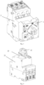
- Figs. 1 and 2 show perspective views of an extension handle assembly 1 according to the present disclosure installed to a motor protection circuit breaker 2.
- the extension handle assembly 1 includes a housing 11 and a handle 12, and the motor protection circuit breaker 2 includes a housing 21 and a knob 22.
- the housing 11 of the extension handle assembly is installed to the housing 21 of the motor protection circuit breaker 2
- the handle 12 of the extension handle assembly 1 is installed to the knob 22 of the motor protection circuit breaker 2.
- the specific way of installing the housing of the extension handle assembly 1 to the housing of the motor protection circuit breaker 2 is well known to those skilled in the art, and has nothing to do with the purpose of the present disclosure, so the repeated portions will be omitted here, and those skilled in the art can choose an appropriate way to install the two housings together.
- the specific way of installing the handle 12 of the extension handle assembly 1 to the knob 22 of the motor protection circuit breaker 2 is well known to those skilled in the art, as long as the handle and knob can be installed together so that they can finally rotate together.
- the handle 12 of the extension handle assembly may include a groove, a part of the knob 22 of the motor protection circuit breaker can be inserted into the groove, so that the handle 12 is installed to the knob 22.
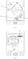
- Fig. 3 shows a perspective view of an extension handle assembly 1 according to the present disclosure.
- the handle 22 is installed to the housing, and a part of the handle 22 can protrude to the outside of the housing through an opening of the housing, so that a user can directly operate the handle or operate the handle with other operating members.
- the extension handle assembly 1 further includes a stopper 13 disposed in the housing 1, the stopper 13 is pivotally installed in the housing 1, as illustrated by Fig. 4 .
- the stopper 13 includes a pivot shaft 131, a main body 132 and a first stop part 133 protruding from the main body.
- a part of the extension handle assembly 1 abuts against the first stop part 133 of the stopper 13.
- the handle 12 is stopped by the first stop part 133, which makes it need to increase a rotating force applied to the handle to rotate the handle 12, and further makes the first stop part 133 drive the stopper 13 to pivot around the pivot shaft 131 (clockwise in Fig. 4 ), so that the stopper 13 finally pivot away from a rotation path of the handle.
- the rotation of the handle 12 will directly drive the knob 22 of the motor circuit breaker to start rotating, and finally switch the motor circuit breaker from the ON state to the manual tripping state, as illustrated by Figs. 7 and 8 .
- the extension handle assembly 1 further includes a return spring 14, which provides a return force for the stopper 13 to return after the stopper 13 is separated from the rotation path of the handle 12.
- the return spring 14 is in the form of a torsion spring, but other suitable forms are also possible.
- the stopper by arranging the stopper, the force required by using the extension handle assembly to control the motor protection circuit breaker to switch from the ON state to the manual tripping state can be increased, and the occurrence of accidental switch can be reduced.
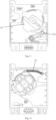
- the knob 22 of the motor protection circuit breaker Upon a fault tripping occurring, the knob 22 of the motor protection circuit breaker first starts to rotate (which is determined by the operation of the fault tripping of the motor protection circuit breaker and is well known to those skilled in the art), thereby driving the handle 12 of the extension handle assembly to rotate from the first position to the third position.
- Figs. 9 and 10 both show that the knob 22 of the motor protection circuit breaker abuts against the handle 12 after being rotated counterclockwise by the predetermined angle ⁇ .
- S1 of Fig. 9 represents a position before the knob 22 is rotated
- FIG. 9 represents a position after the knob 22 is rotated.
- the knob 22 upon the knob 22 of the motor protection circuit breaker starting to rotate, due to the existence of the predetermined angle ⁇ , the knob 22 will not directly drive the handle 12 to rotate, but will first rotate by a predetermined angle and reach the state shown in Fig. 9 (this process can also be called "idling").
- a part of the knob 22 will abut against a second stop part 134 of the stopper to push the second stop part 134, so that the second stop part 134 drives the stopper to rotate, so that the first stop part leaves the rotation path of the handle to be rotated later (as illustrated by Fig.
- the first stop part 131 has left the rotation path of the handle 12, and the handle 12 will not be stopped by the first stop part). From the state of Fig. 9 , the knob 22 abuts against the handle 12, so as to drive the handle 12 to rotate in the counterclockwise direction as illustrated by Fig. 9 . Because there is no stopper on the rotation path of the handle 12, the rotation of the handle 12 is not stopped at all, and finally rotates to the third position, as illustrated by the front view of Fig. 11 and the back view of Fig. 12 .
- the extension handle assembly 1 further includes a biasing member 15 connected between the handle and the housing and configured to provide a biasing force to rotate the handle toward the second position or the third position at the first position of the handle.
- the biasing member 15 is in the form of a tension spring.
- the biasing member 15 At a first position, as shown most clearly in Fig. 6 , the biasing member 15 is in a tension state and stores energy, at this time, the biasing member 15 provides a biasing force to rotate the handle from the first position to the second position or the third position; at the second position shown in Fig. 8 , the biasing member 15 is in a state of no energy storage; at the third position shown in Fig. 11 , the biasing member 15 is still in a stretched state and stores energy, but compared with Fig. 6 , at this time, the biasing member 15 has released some energy.
- the extension handle assembly 1 further includes locking members for locking the handle 12 at the first position, the second position or the third position, and these locking members are irrelevant to the inventive purpose of the present application, so the relevant description thereof is omitted here.
- the extension handle assembly including the stopper, the force required by using the extension handle assembly to control the motor protection circuit breaker to switch from the ON state to the manual tripping state can be increased, and the occurrence of accidental switch can be reduced, while the switch of the motor protection circuit breaker from the ON state to the fault tripping state is not hindered.
Landscapes
- Breakers (AREA)
Applications Claiming Priority (1)
| Application Number | Priority Date | Filing Date | Title |
|---|---|---|---|
| CN202210774737 | 2022-07-01 |
Publications (2)
| Publication Number | Publication Date |
|---|---|
| EP4300537A1 true EP4300537A1 (de) | 2024-01-03 |
| EP4300537B1 EP4300537B1 (de) | 2026-04-22 |
Family
ID=84074909
Family Applications (1)
| Application Number | Title | Priority Date | Filing Date |
|---|---|---|---|
| EP23306058.1A Active EP4300537B1 (de) | 2022-07-01 | 2023-06-29 | Motorschutzschalter mit einer anordnung zur griffverlängerung |
Country Status (3)
| Country | Link |
|---|---|
| US (1) | US12381059B2 (de) |
| EP (1) | EP4300537B1 (de) |
| CN (1) | CN217881372U (de) |
Families Citing this family (1)
| Publication number | Priority date | Publication date | Assignee | Title |
|---|---|---|---|---|
| WO2025251073A1 (en) * | 2024-05-31 | 2025-12-04 | Control Concepts Corp Dba C3Controls | Circuit breaker |
Citations (3)
| Publication number | Priority date | Publication date | Assignee | Title |
|---|---|---|---|---|
| DE4312428C1 (de) * | 1993-04-19 | 1994-11-03 | Kloeckner Moeller Gmbh | Handbetätigungsvorrichtung für gekapselte elektrische Schaltgeräte |
| US6606229B2 (en) * | 2000-10-10 | 2003-08-12 | Fuji Electric Co., Ltd. | Handle operating mechanism in circuit breaker |
| EP2806447A1 (de) * | 2013-05-21 | 2014-11-26 | LSIS Co., Ltd. | Kupplungsvorrichtung für einen Trennschalter |
Family Cites Families (3)
| Publication number | Priority date | Publication date | Assignee | Title |
|---|---|---|---|---|
| US4506121A (en) * | 1982-11-10 | 1985-03-19 | Cooper Industries, Inc. | Anti-overload operating linkage for enclosed interlocked receptacle with safety switch or circuit breaker |
| US5288958A (en) * | 1992-03-30 | 1994-02-22 | Westinghouse Electric Corp. | Lockable remote rotary handle operator for circuit breakers |
| KR200440107Y1 (ko) * | 2006-12-29 | 2008-05-26 | 엘에스산전 주식회사 | 모터 보호용 배선용 차단기의 인클로져 |
-
2022
- 2022-08-05 CN CN202222071221.0U patent/CN217881372U/zh active Active
-
2023
- 2023-06-28 US US18/215,398 patent/US12381059B2/en active Active
- 2023-06-29 EP EP23306058.1A patent/EP4300537B1/de active Active
Patent Citations (3)
| Publication number | Priority date | Publication date | Assignee | Title |
|---|---|---|---|---|
| DE4312428C1 (de) * | 1993-04-19 | 1994-11-03 | Kloeckner Moeller Gmbh | Handbetätigungsvorrichtung für gekapselte elektrische Schaltgeräte |
| US6606229B2 (en) * | 2000-10-10 | 2003-08-12 | Fuji Electric Co., Ltd. | Handle operating mechanism in circuit breaker |
| EP2806447A1 (de) * | 2013-05-21 | 2014-11-26 | LSIS Co., Ltd. | Kupplungsvorrichtung für einen Trennschalter |
Also Published As
| Publication number | Publication date |
|---|---|
| CN217881372U (zh) | 2022-11-22 |
| EP4300537B1 (de) | 2026-04-22 |
| US12381059B2 (en) | 2025-08-05 |
| US20240006141A1 (en) | 2024-01-04 |
Similar Documents
| Publication | Publication Date | Title |
|---|---|---|
| JP3329654B2 (ja) | 電動芝刈機の操作スイッチ | |
| US6518526B2 (en) | Handle-operating mechanism for a circuit breaker including intermeshing handle clutch gear and operator toggle gear | |
| US7111877B2 (en) | Latch with uni-directional power release mechanism | |
| EP4300537A1 (de) | Verlängerungsgriffanordnung für motorschutzschalter und motorschutzschalter | |
| US9754737B2 (en) | Electrical switching apparatus and stored energy assembly therefor | |
| JPH0869030A (ja) | レンズカバー駆動装置 | |
| WO2017193498A1 (zh) | 定时组件及电烤箱 | |
| JP2008123727A (ja) | 開閉器および開閉器操作機構 | |
| US2972687A (en) | Directional control for synchronous motors | |
| CN111128625A (zh) | 一种断路器自动分合闸装置的传动机构 | |
| JPH10205639A (ja) | バルブ用アクチュエータ | |
| JP3738591B2 (ja) | 遮断器の操作装置 | |
| CN116705529A (zh) | 一种弹簧操动机构 | |
| CN211016976U (zh) | 一种断路器分合闸装置的分闸机构 | |
| CN211182131U (zh) | 一种断路器自动分合闸装置的传动机构 | |
| CN211182129U (zh) | 一种断路器自动分合闸装置的分合闸机构 | |
| JP3182042B2 (ja) | 開閉装置の操作機構 | |
| CN224110160U (zh) | 双电源转换开关 | |
| CN217933669U (zh) | 一种断路器操作机构 | |
| JP3148717B2 (ja) | 開閉器の操作装置 | |
| CN223911553U (zh) | 储能指示件及双电源转换开关 | |
| CN224005797U (zh) | 操作机构和隔离开关 | |
| CN216957939U (zh) | 断路器 | |
| KR910003312Y1 (ko) | Tv스피커 수납장치 | |
| US5193078A (en) | Uni-directional rotation device for a cam-operated timer |
Legal Events
| Date | Code | Title | Description |
|---|---|---|---|
| PUAI | Public reference made under article 153(3) epc to a published international application that has entered the european phase |
Free format text: ORIGINAL CODE: 0009012 |
|
| STAA | Information on the status of an ep patent application or granted ep patent |
Free format text: STATUS: THE APPLICATION HAS BEEN PUBLISHED |
|
| AK | Designated contracting states |
Kind code of ref document: A1 Designated state(s): AL AT BE BG CH CY CZ DE DK EE ES FI FR GB GR HR HU IE IS IT LI LT LU LV MC ME MK MT NL NO PL PT RO RS SE SI SK SM TR |
|
| STAA | Information on the status of an ep patent application or granted ep patent |
Free format text: STATUS: REQUEST FOR EXAMINATION WAS MADE |
|
| 17P | Request for examination filed |
Effective date: 20240607 |
|
| RBV | Designated contracting states (corrected) |
Designated state(s): AL AT BE BG CH CY CZ DE DK EE ES FI FR GB GR HR HU IE IS IT LI LT LU LV MC ME MK MT NL NO PL PT RO RS SE SI SK SM TR |
|
| GRAP | Despatch of communication of intention to grant a patent |
Free format text: ORIGINAL CODE: EPIDOSNIGR1 |
|
| STAA | Information on the status of an ep patent application or granted ep patent |
Free format text: STATUS: GRANT OF PATENT IS INTENDED |
|
| RIC1 | Information provided on ipc code assigned before grant |
Ipc: H01H 71/56 20060101AFI20251030BHEP |
|
| INTG | Intention to grant announced |
Effective date: 20251114 |
|
| GRAS | Grant fee paid |
Free format text: ORIGINAL CODE: EPIDOSNIGR3 |
|
| GRAA | (expected) grant |
Free format text: ORIGINAL CODE: 0009210 |
|
| STAA | Information on the status of an ep patent application or granted ep patent |
Free format text: STATUS: THE PATENT HAS BEEN GRANTED |
|
| AK | Designated contracting states |
Kind code of ref document: B1 Designated state(s): AL AT BE BG CH CY CZ DE DK EE ES FI FR GB GR HR HU IE IS IT LI LT LU LV MC ME MK MT NL NO PL PT RO RS SE SI SK SM TR |
|
| REG | Reference to a national code |
Ref country code: CH Ref legal event code: F10 Free format text: ST27 STATUS EVENT CODE: U-0-0-F10-F00 (AS PROVIDED BY THE NATIONAL OFFICE) Effective date: 20260422 |