EP4299935A1 - Tripoderoller für ein tripodegelenk und tripodegelenk mit solchen - Google Patents
Tripoderoller für ein tripodegelenk und tripodegelenk mit solchen Download PDFInfo
- Publication number
- EP4299935A1 EP4299935A1 EP23178846.4A EP23178846A EP4299935A1 EP 4299935 A1 EP4299935 A1 EP 4299935A1 EP 23178846 A EP23178846 A EP 23178846A EP 4299935 A1 EP4299935 A1 EP 4299935A1
- Authority
- EP
- European Patent Office
- Prior art keywords
- tripod
- inner ring
- recesses
- ring
- scooter
- Prior art date
- Legal status (The legal status is an assumption and is not a legal conclusion. Google has not performed a legal analysis and makes no representation as to the accuracy of the status listed.)
- Granted
Links
Images




Classifications
-
- F—MECHANICAL ENGINEERING; LIGHTING; HEATING; WEAPONS; BLASTING
- F16—ENGINEERING ELEMENTS AND UNITS; GENERAL MEASURES FOR PRODUCING AND MAINTAINING EFFECTIVE FUNCTIONING OF MACHINES OR INSTALLATIONS; THERMAL INSULATION IN GENERAL
- F16D—COUPLINGS FOR TRANSMITTING ROTATION; CLUTCHES; BRAKES
- F16D3/00—Yielding couplings, i.e. with means permitting movement between the connected parts during the drive
- F16D3/16—Universal joints in which flexibility is produced by means of pivots or sliding or rolling connecting parts
- F16D3/20—Universal joints in which flexibility is produced by means of pivots or sliding or rolling connecting parts one coupling part entering a sleeve of the other coupling part and connected thereto by sliding or rolling members
- F16D3/202—Universal joints in which flexibility is produced by means of pivots or sliding or rolling connecting parts one coupling part entering a sleeve of the other coupling part and connected thereto by sliding or rolling members one coupling part having radially projecting pins, e.g. tripod joints
- F16D3/205—Universal joints in which flexibility is produced by means of pivots or sliding or rolling connecting parts one coupling part entering a sleeve of the other coupling part and connected thereto by sliding or rolling members one coupling part having radially projecting pins, e.g. tripod joints the pins extending radially outwardly from the coupling part
- F16D3/2055—Universal joints in which flexibility is produced by means of pivots or sliding or rolling connecting parts one coupling part entering a sleeve of the other coupling part and connected thereto by sliding or rolling members one coupling part having radially projecting pins, e.g. tripod joints the pins extending radially outwardly from the coupling part having three pins, i.e. true tripod joints
-
- F—MECHANICAL ENGINEERING; LIGHTING; HEATING; WEAPONS; BLASTING
- F16—ENGINEERING ELEMENTS AND UNITS; GENERAL MEASURES FOR PRODUCING AND MAINTAINING EFFECTIVE FUNCTIONING OF MACHINES OR INSTALLATIONS; THERMAL INSULATION IN GENERAL
- F16B—DEVICES FOR FASTENING OR SECURING CONSTRUCTIONAL ELEMENTS OR MACHINE PARTS TOGETHER, e.g. NAILS, BOLTS, CIRCLIPS, CLAMPS, CLIPS OR WEDGES; JOINTS OR JOINTING
- F16B21/00—Means for preventing relative axial movement of a pin, spigot, shaft or the like and a member surrounding it; Stud-and-socket releasable fastenings
- F16B21/09—Releasable fastening devices with a stud engaging a keyhole slot
-
- F—MECHANICAL ENGINEERING; LIGHTING; HEATING; WEAPONS; BLASTING
- F16—ENGINEERING ELEMENTS AND UNITS; GENERAL MEASURES FOR PRODUCING AND MAINTAINING EFFECTIVE FUNCTIONING OF MACHINES OR INSTALLATIONS; THERMAL INSULATION IN GENERAL
- F16C—SHAFTS; FLEXIBLE SHAFTS; ELEMENTS OR CRANKSHAFT MECHANISMS; ROTARY BODIES OTHER THAN GEARING ELEMENTS; BEARINGS
- F16C19/00—Bearings with rolling contact, for exclusively rotary movement
- F16C19/22—Bearings with rolling contact, for exclusively rotary movement with bearing rollers essentially of the same size in one or more circular rows, e.g. needle bearings
- F16C19/34—Bearings with rolling contact, for exclusively rotary movement with bearing rollers essentially of the same size in one or more circular rows, e.g. needle bearings for both radial and axial load
- F16C19/36—Bearings with rolling contact, for exclusively rotary movement with bearing rollers essentially of the same size in one or more circular rows, e.g. needle bearings for both radial and axial load with a single row of rollers
-
- F—MECHANICAL ENGINEERING; LIGHTING; HEATING; WEAPONS; BLASTING
- F16—ENGINEERING ELEMENTS AND UNITS; GENERAL MEASURES FOR PRODUCING AND MAINTAINING EFFECTIVE FUNCTIONING OF MACHINES OR INSTALLATIONS; THERMAL INSULATION IN GENERAL
- F16C—SHAFTS; FLEXIBLE SHAFTS; ELEMENTS OR CRANKSHAFT MECHANISMS; ROTARY BODIES OTHER THAN GEARING ELEMENTS; BEARINGS
- F16C33/00—Parts of bearings; Special methods for making bearings or parts thereof
- F16C33/30—Parts of ball or roller bearings
-
- F—MECHANICAL ENGINEERING; LIGHTING; HEATING; WEAPONS; BLASTING
- F16—ENGINEERING ELEMENTS AND UNITS; GENERAL MEASURES FOR PRODUCING AND MAINTAINING EFFECTIVE FUNCTIONING OF MACHINES OR INSTALLATIONS; THERMAL INSULATION IN GENERAL
- F16C—SHAFTS; FLEXIBLE SHAFTS; ELEMENTS OR CRANKSHAFT MECHANISMS; ROTARY BODIES OTHER THAN GEARING ELEMENTS; BEARINGS
- F16C33/00—Parts of bearings; Special methods for making bearings or parts thereof
- F16C33/30—Parts of ball or roller bearings
- F16C33/66—Special parts or details in view of lubrication
-
- F—MECHANICAL ENGINEERING; LIGHTING; HEATING; WEAPONS; BLASTING
- F16—ENGINEERING ELEMENTS AND UNITS; GENERAL MEASURES FOR PRODUCING AND MAINTAINING EFFECTIVE FUNCTIONING OF MACHINES OR INSTALLATIONS; THERMAL INSULATION IN GENERAL
- F16D—COUPLINGS FOR TRANSMITTING ROTATION; CLUTCHES; BRAKES
- F16D3/00—Yielding couplings, i.e. with means permitting movement between the connected parts during the drive
- F16D3/16—Universal joints in which flexibility is produced by means of pivots or sliding or rolling connecting parts
- F16D3/20—Universal joints in which flexibility is produced by means of pivots or sliding or rolling connecting parts one coupling part entering a sleeve of the other coupling part and connected thereto by sliding or rolling members
- F16D3/202—Universal joints in which flexibility is produced by means of pivots or sliding or rolling connecting parts one coupling part entering a sleeve of the other coupling part and connected thereto by sliding or rolling members one coupling part having radially projecting pins, e.g. tripod joints
- F16D2003/2026—Universal joints in which flexibility is produced by means of pivots or sliding or rolling connecting parts one coupling part entering a sleeve of the other coupling part and connected thereto by sliding or rolling members one coupling part having radially projecting pins, e.g. tripod joints with trunnion rings, i.e. with tripod joints having rollers supported by a ring on the trunnion
-
- F—MECHANICAL ENGINEERING; LIGHTING; HEATING; WEAPONS; BLASTING
- F16—ENGINEERING ELEMENTS AND UNITS; GENERAL MEASURES FOR PRODUCING AND MAINTAINING EFFECTIVE FUNCTIONING OF MACHINES OR INSTALLATIONS; THERMAL INSULATION IN GENERAL
- F16D—COUPLINGS FOR TRANSMITTING ROTATION; CLUTCHES; BRAKES
- F16D2300/00—Special features for couplings or clutches
- F16D2300/06—Lubrication details not provided for in group F16D13/74
-
- Y—GENERAL TAGGING OF NEW TECHNOLOGICAL DEVELOPMENTS; GENERAL TAGGING OF CROSS-SECTIONAL TECHNOLOGIES SPANNING OVER SEVERAL SECTIONS OF THE IPC; TECHNICAL SUBJECTS COVERED BY FORMER USPC CROSS-REFERENCE ART COLLECTIONS [XRACs] AND DIGESTS
- Y10—TECHNICAL SUBJECTS COVERED BY FORMER USPC
- Y10S—TECHNICAL SUBJECTS COVERED BY FORMER USPC CROSS-REFERENCE ART COLLECTIONS [XRACs] AND DIGESTS
- Y10S464/00—Rotary shafts, gudgeons, housings, and flexible couplings for rotary shafts
- Y10S464/904—Homokinetic coupling
- Y10S464/905—Torque transmitted via radially extending pin
Definitions
- the invention relates to a tripod scooter for a tripod joint with the features of the preamble of patent claim 1. Furthermore, the invention relates to a tripod joint with such tripod scooters.
- Tripod roller comprising an outer ring with an annular tread on its outer circumference for rolling in a tripod housing and with an inner circumferential surface, an inner ring with an annular tread on its inner circumference for storage on a pin of a tripod star and with an outer circumferential surface and opposite end faces, rolling elements, which are in one Annular space between the inner circumferential surface of the outer ring and the outer circumferential surface of the inner ring are arranged and via which the outer ring is rotatably mounted with its inner circumferential surface on the outer circumferential surface of the inner ring, and axial locking rings, which are fixed to the outer ring and secure the outer ring axially relative to the inner ring, as well as corresponding ones Tripod joints, for example, are out DE 10 2009 041 086 A1 and DE 10 2020 212 991 A1 known.
- Such tripod rollers and tripod joints are used, for example, in side shafts on the drive side of motor vehicles. Their main functions are the transmission of torque and power from the drive to the wheel as well as bending and length compensation with simultaneous steering and spring movements as well as unit movements.
- a generic tripod scooter for a tripod joint with the features of the preamble of claim 1 is out JP 2019-124253 A known.
- JP 2019-124253 A JP 2019-124253 A known.
- the purpose of these bags is to store lubricant in case of shortage situations in order to protect the contact surfaces between the Lubricate the inner circumferential surface of the inner ring and the outer circumferential surface of the pin.
- the invention is based on the object of creating tripod scooters of the type mentioned, which have an improved service life with a compact design and high load.
- a tripod scooter according to claim 1.
- the inner ring has recesses on at least one of its end faces for receiving lubricant, the recesses on the outer peripheral surface of the inner ring opening into the annular space in which the rolling elements are arranged in order to supply the rolling elements with lubricant.
- the recesses can be realized without much additional manufacturing effort. For example, these can be taken into account when shaping the inner ring, which is usually forged.
- the supporting length of the rolling elements in the axial direction is smaller than the length of the inner ring on its outer peripheral surface in the axial direction.
- the depression of the recesses in the end face at their respective opening into the annular space can be smaller than the difference between the length of the inner ring and the supporting length.
- the recesses in the end face at their respective mouths into the annular space be less than half the difference between the length of the inner ring and the supporting length.
- the recesses on the end face of the inner ring open into the inner circumferential surface of the inner ring, whereby a channel is provided across the entire end face for the transport of lubricant.
- the recesses on the end face of the inner ring can be designed as grooves with a cross section that is constant in the longitudinal direction of the respective groove.
- the recesses on the end face of the inner ring can be recessed more deeply into the end face at their mouth into the annular space than at their mouth into the inner circumferential surface of the inner ring.
- the recesses on the end face of the inner ring can be designed as grooves which are more deeply recessed at their mouth into the inner circumferential surface of the inner ring than at their mouth into the annular space.
- the width of the grooves can decrease from the opening into the inner circumferential surface of the inner ring to the opening into the annular space.
- the recesses on the end face of the inner ring can be designed as pockets which only open into the annular space, that is to say have no opening into the inner circumferential surface of the inner ring.
- the pockets preferably extend radially inwards from the outer circumferential surface of the inner ring to only half or up to two thirds of the inner ring thickness.
- the recesses can be designed as grooves connecting the annular space with the inner circumferential surface of the inner ring, which are curved in an arc shape towards a radial direction of the inner ring.
- the curvature of the grooves on the opposite end faces can be opposite to one another.
- lubricant is supplied on one side and used lubricant is removed or pumped out of the rolling element contact on the other side.
- recesses for receiving lubricant are formed on the axial locking ring on an inside facing the inner ring in order to convey lubricant more effectively to the rolling elements.
- the recesses on the axial locking ring can, for example, comprise radial grooves which extend radially from an inner edge of the axial locking ring at least to the level of the annular space.
- these radial grooves can extend continuously extend over the entire face of the axial lock or as a pocket only up to the middle or last third of the ring height.
- the recesses on the axial locking ring can comprise axial grooves which open into the annular space and are designed to run obliquely or axially on the inner edge of the axial locking ring.
- the radial grooves and the axial grooves can be provided together on an axial locking ring and can preferably, but not necessarily, be connected to one another.
- tripod rollers explained above enable a tripod joint according to claim 15, comprising a tripod star with radially projecting pins, a tripod roller of the type explained above being mounted on each pin, and a tripod housing with a pair of raceways per tripod roller for guiding the annular running surface of the outer ring of the respective tripod roller .
- Such a tripod joint is characterized by a compact design and a long service life. It is particularly suitable for high torques and alternating loads, such as those found in electric vehicle drives.
- Fig. 1 and 2 show a possible embodiment of a tripod joint 1 according to the invention, which can be used, for example, in a side shaft of a motor vehicle as a drive-side constant velocity joint.
- the tripod joint 1 comprises an inner joint part in the form of a tripod star 10 with an axis of rotation A and an outer joint part in the form of a tripod housing 20 with an axis of rotation B.
- pairs of raceways 21 are formed on the inside, in which the inner joint part is guided axially, ie in the direction of the axis of rotation B is.
- the tripod joint 1 is stretched, the axes of rotation A and B are aligned with each other. If the tripod joint 1 is bent during operation, they enclose a bending angle not equal to 0°, as shown in Fig. 1 is shown as an example.
- the tripod star 10 has a central shaft section 11 and several, preferably three, pins 12 projecting from the shaft section 11.
- the central shaft section 11 can be designed as a ring body, which can be coupled to a shaft.
- the pins 12 are arranged at the same distance from one another in the circumferential direction around the axis of rotation A of the inner joint part or tripod star 10.
- Their longitudinal axes Z run essentially radially to the axis of rotation A and are preferably located, as in the exemplary embodiment shown in Fig. 2 shown in a common plane.
- the tripod joint 1 on the tripod star 10 includes a tripod roller 30 for each pin 12, which is rotatably mounted on the associated pin 12 of the tripod star 10 about the longitudinal axis Z of the pin 12.
- the pins 12 each have a profiled surface 13 for supporting the tripod scooter 30, which is explained in more detail below.
- Each tripod roller 30 comprises an outer ring 31 and an inner ring 32 as well as rolling elements 33 arranged between them, so that the outer ring 31 and the inner ring 32 can be rotated relative to one another.
- the outer ring 31 and the inner ring 32 are preferably designed as rotationally symmetrical components.
- the outer ring 31 has on its outer circumference an annular running surface 31a for rolling on a pair of raceways 21 of the tripod housing 20, as well as an inner circumferential surface 31b.
- the inner ring 32 has on its inner circumference an annular running surface 32a for storage on the pin 12 of the tripod star 10 as well as an outer circumferential surface 32b and opposite end faces 32c and 32d.
- the rolling bodies 33 which are preferably designed as needles or rollers, are arranged in an annular space 34 between the inner circumferential surface 31b of the outer ring 31 and the outer circumferential surface 32b of the inner ring 32.
- the annular space 34 runs around the pin 12.
- the outer ring 31 is rotatably mounted with its inner peripheral surface 31b on the outer peripheral surface 32b of the inner ring 32 via the rolling elements 33.
- the rolling bodies 33 each have line contact with the inner circumferential surface 31b of the outer ring 31 and with the outer circumferential surface 32b of the inner ring 32.
- axial locking rings 40 are provided, which are fixed 31 to the outer ring and secure the outer ring 31 axially relative to the inner ring 32.
- the axial locking rings 40 are slotted radially for assembly and have, for example, a rectangular cross section. They are inserted into corresponding grooves on the inner peripheral surface 31b of the outer ring 31.
- the annular space 34 is closed by the inner sides 40a of the axial locking rings 40 arranged axially on both sides of the annular space 34.
- the axial locking rings 40 also ensure that the rolling elements 33 cannot migrate sideways out of the annular space 34.
- the rolling bodies 33 have spherical end sections 33a at their axial ends.
- the supporting length I w of the rolling elements 33 in the axial direction is smaller than the length I IR of the inner ring 32 on its outer peripheral surface 32b in the axial direction.
- Each tripod scooter 30 can roll with the annular running surface 31a of its outer ring 31 along a pair of raceways 21 of the outer joint part or tripod housing 20.
- the profile of the annular running surface 31a can be curved outwards in a spherical cross section.
- the raceways of the pair of raceways 21 can accordingly have a concave cross-sectional profile, as shown in Fig. 2 can be recognized.
- the inner ring 32 is in contact with its inner peripheral surface 32a with the associated pin 12 of the tripod star 10.
- the inner circumferential surface 32a of the inner ring 32 can be circular-cylindrical.
- inner and outer circumferences are understood to be the relevant surfaces and not as dimensions.
- the profiled surface 13 of the pin 12 can be spherically curved in a longitudinal sectional plane which contains the longitudinal axis Z of the respective pin 12.
- the inner ring 32 Due to the spherical design of the surface 13 of the pin 12, with which the inner circumferential surface 32a of the inner ring 32 is in contact, the inner ring 32 can be tilted relative to the longitudinal axis Z of the associated pin 12 when the tripod joint 1 is bent. In addition, there is axial displaceability in the direction of the longitudinal axis Z of the pin 12.
- the outer joint part or tripod housing 20 has its own engagement section for each tripod scooter 30.
- the engagement section is, for example, designed like a sleeve and can have a constant cross-sectional profile over its axial length.
- the engagement section has pairs of raceways 21 on its inner circumference parallel to the axis of rotation B of the tripod housing 20 with raceways opposite one another in the circumferential direction. These raceways are in engagement with the running surface 31a on the outer circumference of the respective tripod scooter 30, with one of the raceways 21 on the tripod housing 20 being load-bearing and the opposite raceway being relieved, depending on the direction of rotation and operating situation.
- the raceways 21 on the tripod housing 20 preferably each run parallel to the axis of rotation B of the tripod housing 20.
- the tripod rollers 30 By profiling both the raceways 21 on the tripod housing 20 and the annular running surfaces 31a of the outer rings 31 of the tripod rollers 30, when the joint 1 is rotated while the component axes A and B are bent relative to one another, the tripod rollers 30 are axially parallel to the axis of rotation B of the tripod housing 20 can be moved back and forth.
- a degree of pivoting freedom required for this can be provided, for example, between the pins 12 and the inner rings 32 of the tripod scooter 30, as has already been explained above.
- the inner ring 32 has recesses 35 on at least one of its end faces 32c, 32d for receiving lubricant.
- the recesses 35 in the end faces 32c, 32d are configured in such a way that they open into the annular space 34, in which the rolling elements 33 are arranged in order to supply the rolling elements 33 with lubricant.
- At least one of the axial locking rings 40 has recesses 41 for receiving lubricant, the recesses 41 in turn opening into the annular space 34 in which the rolling bodies 33 are arranged in order to supply the rolling bodies 33 with lubricant.
- both measures namely recesses 35 on the inner ring side and recesses 41 on the axial locking ring side, can be combined with one another.
- the recesses 35 and 41 are preferably depressions in the respective surfaces 32c, 32d and 40a and 43.
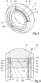
- the Figures 3 and 4 show a first embodiment variant with recesses 35 on the end faces 32c and 32d of the inner ring 32.
- the recesses 35 are designed as grooves 36 with a preferably constant cross section in the longitudinal direction of the respective groove 36. These grooves 36 not only open into the annular space 34, i.e. not only cut into the outer peripheral surface 32b of the inner ring 32, but also open into it at the same time Inner peripheral surface 32a of the inner ring 32 and cut it. In this way, lubricant can reach the otherwise enclosed annular space 34 from outside via the recesses 35 or grooves 36 in order to lubricate the rolling elements 33.
- the recesses 35 are preferably provided on both axial end faces 32c, 32d.
- the supporting length Iw of the rolling elements 33 in the axial direction is preferably chosen to be smaller than the length I IR of the inner ring 32 on its outer peripheral surface 32b in the axial direction.
- the recess t of the recesses 35 in the end face 32c, 32d at their respective mouths into the annular space 34 is preferably chosen to be smaller than half of the difference between the length IIR of the inner ring 32 and the supporting length IW .
- the recess t of the recesses 35 in the end face 32c, 32d at their respective mouth into the annular space 34 can also be selected in this way that this is smaller than the difference between the length I IR of the inner ring 32 and the supporting length Iw.
- the 5 and 6 show a second embodiment variant with recesses 35 on the end faces 32c and 32d of the inner ring 32.
- the recesses 35 are again designed as grooves 36, which, however, compared to the embodiment variant in the 3 and 4 do not run parallel to the plane of the respective end faces 32c and 32d, but rather are beveled. Suitable bevel angles to the plane are in the range of 5 to 20°.
- the recesses 35 can, for example, be more deeply recessed at their mouth into the inner circumferential surface 32a of the inner ring 32 than at their mouth into the annular space 34.
- the depression t 2 at the mouth into the inner peripheral surface 32a is larger than the depression t 1 at the mouth into the annular space 34.
- the recesses 35 on the end face 32c, 32d of the inner ring 32 can be recessed more deeply into the end face 32c, 32d at their mouth into the annular space 34 than at their mouth into the inner circumferential surface 32a of the inner ring 32.
- t is 1 greater than t 2 .
- the width of the grooves 36 decrease from the mouth into the inner circumferential surface 32a of the inner ring 32 to the mouth into the annular space 34.
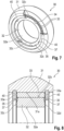
- the recesses 35 are formed by pockets 37 in the end face 32c, 32d for receiving lubricant.
- the pockets 37 only open into the annular space 34, but do not cut into the inner circumferential surface 32a of the inner ring 32, but rather end radially inwards on the respective end face 32c, 32d. They are preferably designed in such a way as to ensure that lubricant is transported from outside into the annular space 34.
- the pockets 37 preferably extend further radially inwards than the axial locking rings 40.
- the 9 and 10 show a further design feature as part of a fourth embodiment variant, which can be combined with the design features for the recesses 35 explained above.
- the recesses 35 of the end faces 32c, 32d can be designed as grooves 36 connecting the annular space 34 with the inner circumferential surface 32a of the inner ring 32, which are curved in an arc shape to a radial direction r of the inner ring 32. The curvature occurs in the plane of the respective end face 32c, 32d.
- the recesses 35 When viewed perpendicular to the end face 32c, the recesses 35 are in the shape of a paddle wheel. This causes an active conveying effect for the lubricant when the tripod roller 30 rotates. Since the tripod scooters are 30 when driving If the tripod roller performs a continuous oscillating rolling movement, a rotating relative movement constantly takes place between the outer ring 31 and the inner ring 32, which enables the conveying effect for the lubricant in order to introduce lubricant from outside into the annular space 34.
- paddle wheel-shaped recesses 35 are designed in opposite directions on an inner ring 32 on the two opposite axial end faces 32c and 32d, depending on the direction of rotation, one side acts to supply lubricant and the other side to remove lubricant. This allows a very good supply of lubricant to the rolling elements 32 and their contact points with the outer ring 31 and the inner ring 32.
- the Fig. 11 and 12 show a fifth embodiment variant to improve the lubricant supply, in which 41 are provided for the transport of lubricant on the axial locking ring 40.
- these recesses 41 are formed on a side 40a of the axial locking ring 40 facing the inner ring 32 in order to effectively convey lubricant to the rolling elements 33.
- these recesses 41 on the axial locking ring 40 include radial grooves 42, which extend radially from an inner edge 43 of the axial locking ring 40 at least to the level of the annular space 34.
- the radial grooves 42 extend from the inner edge 43 preferably to the middle or the last third of the ring height of the axial locking ring 40 in the radial direction.
- radial grooves 42 extend continuously over the entire inner ring 32 and the inside 40a of the respective axial locking ring 40 facing the annular space 34 extends.
- the recesses 41 on the axial locking ring 40 can comprise axial grooves 44, as in a seventh embodiment variant in 15 and 16 is shown. These axial grooves 44 are cut into the inner edge 43 of the axial locking ring 40 in such a way that they open into the annular space 34 for the purpose of external lubricant supply.
- the axial grooves 44 can preferably be designed to run axially, ie parallel to the longitudinal central axis of the axial locking ring 40, on the inner edge 43 of the axial locking ring 40. However, it is also possible to set them slightly obliquely compared to such an axial course, for example in an angular range of up to 30°.
- the radial grooves 42 and the axial grooves 44 can be provided together on an axial locking ring 40. These can optionally be connected to one another. However, it is also possible to arrange them next to each other, unconnected.
- the tripod joints explained above are particularly suitable for motor vehicles with electric drives and comparable drive conditions with high torques and strong alternating loads.
- the strength and acoustic properties of the Tripoderoller 30 remain unaffected.
- the formation of recesses 35 on the inner ring 32 can be integrated into a forging process for its production.
- the additional manufacturing effort remains minimal, as only the forging tool needs to be adjusted.
- additional recesses 41 on the axial locking ring 40 can be achieved very easily by an additional step in the punching process for the axial locking ring 40.
- Tripod joint 36 groove 10 Tripod star (inner part of the joint) 37 Bag 11 Wave section 40 Axial locking ring 12 Cones 40a inside 13 Surface of the tenon 41 Recess on the axial locking ring 20 Tripod housing (joint outer part) 21 career 42 Radial groove 30 Tripod scooter 43 Inside edge 31 Outer ring 44 Axial groove 31a Tread/outer circumferential surface of the outer ring A Axis of rotation of the tripod star (inner joint part) 31b Inner peripheral surface of the outer ring b Axis of rotation of the tripod housing (outer joint part) 32 Inner ring Z Trunnion axis 32a Running surface/inner circumferential surface of the inner ring I w Bearing width of the rolling element I IR Length of the inner circumferential surface of the inner ring in the axial direction 32b Outer circumferential surface of the inner ring r Radial direction 32c Face of the inner ring t deepening 32d Face of the inner ring t1 Deepening of
Landscapes
- Engineering & Computer Science (AREA)
- General Engineering & Computer Science (AREA)
- Mechanical Engineering (AREA)
- Rolling Contact Bearings (AREA)
Abstract
Description
- Die Erfindung bezieht sich auf einen Tripoderoller für ein Tripodegelenk mit den Merkmalen des Oberbegriffs von Patentanspruch 1, . Weiterhin bezieht sich die Erfindung auf ein Tripodegelenk mit solchen Tripoderollern.
- Tripoderoller umfassend einen Außenring mit einer ringförmigen Lauffläche an seinem Außenumfang zum Abrollen in einem Tripodegehäuse sowie mit einer Innenumfangsfläche, einen Innenring mit einer ringförmigen Lauffläche an seinem Innenumfang zur Lagerung an einem Zapfen eines Tripodesterns sowie mit einer Außenumfangsfläche und gegenüberliegende Stirnseiten, Wälzkörper, die in einem Ringraum zwischen der Innenumfangsfläche des Außenrings und der Außenumfangsfläche des Innenrings angeordnet sind und über welche der Außenring mit seiner Innenumfangsfläche an der Außenumfangsfläche des Innenrings drehbar gelagert ist, und Axialsicherungsringe, welche an dem Außenring festgelegt sind und den Außenring axial gegenüber dem Innenring sichern, sowie entsprechende Tripodegelenke sind beispielsweise aus
DE 10 2009 041 086 A1 undDE 10 2020 212 991 A1 bekannt. - Solche Tripoderoller und Tripodegelenke kommen beispielsweise in Seitenwellen auf der Antriebsseite von Kraftfahrzeugen zum Einsatz. Ihre Hauptfunktionen bestehen in der Momenten- und Leistungsübertragung vom Antrieb zum Rad sowie in der Abbeugung und im Längenausgleich bei gleichzeitigen Lenk- und Federbewegungen sowie Aggregatbewegungen.
- Ein gattungsgemäßer Tripoderoller für ein Tripodegelenk mit den Merkmalen des Oberbegriffs von Patentanspruch 1 ist aus
JP 2019-124253 A - Bei gattungsgemäßen Tripodegelenken treten im Fahrbetrieb insbesondere im Bereich der Tripoderoller hohe Belastungen auf. Dies verschärft sich bei Elektrofahrzeugen durch erhöhte Drehmomente sowie gesteigerte Wechselbelastungen als Folge von Rekuperation.
- Insbesondere bei den vorgenannten Doppelrollen mit einem Außenring und einem Innenring sowie zwischen diesen angeordneten Wälzkörpern kann es zu einem hohen Verschleiß zwischen dem Außenring und den Wälzkörpern sowie ferner zwischen dem Innenring und den Wälzkörpern kommen.
- Dem kann durch eine entsprechende großzügigere Bemessung der Bauteile abgeholfen werden. Dies führt jedoch zu großen Gelenkbaugrößen, welche im Hinblick auf in der Regel sehr enge Bauräume von modernen Fahrzeugen möglichst vermieden werden sollen.
- Ferner könnte erwogen werden, alternative Schmiermittel einzusetzen. Praktische Versuche haben jedoch gezeigt, dass sich hierdurch keine substantielle Lebensdauerverbesserung erzielen lässt.
- Vor diesem Hintergrund liegt der Erfindung die Aufgabe zu Grunde, Tripoderoller der eingangs genannten Art zu schaffen, welche bei kompakter Bauweise und hoher Belastung eine verbesserte Lebensdauer aufweisen.
- Diese Aufgabe wird durch einen Tripoderoller gemäß Patentanspruch 1 gelöst. Dieser zeichnet sich insbesondere dadurch aus, dass der Innenring an mindestens einer seiner Stirnseiten Ausnehmungen zur Aufnahme von Schmiermittel aufweist, wobei die Ausnehmungen an der Außenumfangsfläche des Innenrings in den Ringraum münden, in welchem die Wälzkörper angeordnet sind, um die Wälzkörper mit Schmiermittel zu versorgen.
- Es hat sich gezeigt, dass sich hierdurch die Lebensdauer deutlich verbessern lässt. Über die Ausnehmungen wird trotz praktischer Kapselung des Ringraums durch die Axialsicherungsringe eine verbesserte Schmiermittelzufuhr zu den Kontaktstellen der Wälzkörper mit dem Innenring und dem Außenring erzielt.
- Hierdurch kann wiederum der Einsatz größerer Gelenksbaugrößen vermieden werden, wodurch zudem Gewicht eingespart wird.
- Die Ausnehmungen lassen sich ohne großen fertigungstechnischen Mehraufwand verwirklichen. Beispielsweise können diese bei der Formgebung des Innenrings berücksichtigt werden, welcher üblicherweise geschmiedet wird.
- Besondere Ausführungsarten der Erfindung sind Gegenstand weiterer Patentansprüche.
- Vorzugsweise ist die Traglänge der Wälzkörper in Axialrichtung kleiner als die Länge des Innenrings an seiner Außenumfangsfläche in Axialrichtung. Zudem kann die Eintiefung der Ausnehmungen in die Stirnseite an ihrer jeweiligen Mündung in den Ringraum kleiner sein als die Differenz aus der Länge des Innenrings und der Traglänge. Hierdurch bleiben die Festigkeits- und Akustikeigenschaften des Tripoderollers von den Ausnehmungen weitestgehend unbeeinflusst.
- Sind die axial einander gegenüberliegenden Stirnseiten des Innenrings jeweils mit Ausnehmungen versehen, empfiehlt es sich, die Eintiefung der Ausnehmungen in die Stirnseite an ihrer jeweiligen Mündung in den Ringraum jeweils kleiner als die Hälfte der Differenz aus der Länge des Innenrings und der Traglänge zu wählen.
- Gemäß einer weiteren besonderen Ausführungsart der Erfindung münden die Ausnehmungen an der Stirnseite des Innenrings in die Innenumfangsfläche des Innenrings, wodurch ein Kanal über die gesamte Stirnseite hinweg für den Schmiermitteltransport bereitgestellt wird.
- In einer Ausführungsvariante können die Ausnehmungen an der Stirnseite des Innenrings als Rillen mit einem in Längsrichtung der jeweiligen Rille konstanten Querschnitt ausgebildet sein.
- In einer weiteren Ausführungsvariante können die Ausnehmungen an der Stirnseite des Innenrings an ihrer Mündung in den Ringraum stärker in die Stirnfläche eingetieft sein als an ihrer Mündung in die Innenumfangsfläche des Innenrings.
- In einer weiteren Ausführungsvariante können die Ausnehmungen an der Stirnseite des Innenrings als Rillen ausgebildet sein, welche an ihrer Mündung in die Innenumfangsfläche des Innenrings stärker eingetieft sind als an ihrer Mündung in den Ringraum.
- Ferner kann die Breite der Rillen von der Mündung in die Innenumfangsfläche des Innenrings zu der Mündung in den Ringraum abnehmend sein.
- Gemäß einer weiteren besonderen Ausführungsart können die Ausnehmungen an der Stirnseite des Innenrings als Taschen ausgebildet sein, welche lediglich in den Ringraum münden, das heißt keine Mündung in die Innenumfangsfläche des Innenrings aufweisen. Die Taschen erstrecken sich vorzugsweise lediglich bis zur Hälfte oder bis zu zwei Dritteln der Innenringdicke von der Außenumfangsfläche des Innenrings radial einwärts.
- Gemäß einer weiteren besonderen Ausführungsart der Erfindung können die Ausnehmungen als den Ringraum mit der Innenumfangsfläche des Innenrings verbindende Rillen ausgebildet sein, welche zu einer Radialrichtung des Innenrings bogenförmig gekrümmt sind. Durch eine solche in etwa schaufelradförmige Ausgestaltung führt eine Drehbewegung der Rollen zu einer aktiven Förderwirkung des Schmiermittels und damit zu einer guten Schmierstoffversorgung der Wälzkörper. Im Fahrbetrieb eines Kraftfahrzeugs führen die Tripoderoller eine kontinuierliche oszillierende Abrollbewegung aus. Dabei findet zwischen dem Außenring und dem Innenring eine drehende Relativbewegung statt, welche die Förderwirkung ermöglicht.
- Ferner kann die Krümmung der Rillen an den gegenüberliegenden Stirnseiten entgegengesetzt zueinander sein. Durch eine solche gegensinnige Ausführung wird abhängig von der Drehrichtung an einer Seite Schmiermittel zugeführt und an der anderen Seite verbrauchtes" Schmiermittel aus dem Wälzkörperkontakt abgeführt bzw. abgepumpt.
- Gemäß einer weiteren besonderen Ausführungsart sind Ausnehmungen zur Aufnahme von Schmiermittel am Axialsicherungsring an einer zu dem Innenring weisenden Innenseite ausgebildet, um Schmiermittel wirkungsvoller zu den Wälzkörpern zu fördern.
- Die Ausnehmungen am Axialsicherungsring können beispielsweise Radialrillen umfassen, welche sich von einer Innenkante des Axialsicherungsrings radial zumindest bis auf Höhe des Ringraums erstrecken. Insbesondere können sich diese Radialrillen durchgehend über die gesamte Stirnfläche des Axialsicherung erstrecken oder aber auch als Tasche lediglich bis zur Mitte oder zum letzten Drittel der Ringhöhe.
- Weiterhin können die Ausnehmungen die Ausnehmungen am Axialsicherungsring Axialnuten umfassen, welche in den Ringraum münden und schräg oder axial verlaufend an der Innenkante des Axialsicherungsrings ausgebildet sind.
- Die Radialrillen sowie die Axialnuten können gemeinsam an einem Axialsicherungsring vorgesehen sein und dabei vorzugsweise, jedoch nicht notwendigerweise, untereinander verbunden sein.
- Die vorstehend erläuterten Tripoderoller ermöglichen ein Tripodegelenk gemäß Patentanspruch 15, umfassend einen Tripodesterns mit radial abstehenden Zapfen, wobei an jedem Zapfen ein Tripoderoller der vorstehend erläuterten Art gelagert ist, und einen Tripodegehäuse mit einem Laufbahnpaar je Tripoderoller zur Führung der ringförmigen Lauffläche des Außenrings des jeweiligen Tripoderollers.
- Ein solches Tripodegelenk zeichnet sich durch eine kompakte Bauweise sowie eine hohe Lebensdauer aus. Es eignet sich insbesondere für hohe Drehmomente und Wechselbelastungen, wie sie in Antrieben von Elektrofahrzeugen auftreten.
- Nachfolgend wird die Erfindung anhand eines in der Zeichnung dargestellten Ausführungsbeispiels sowie weiterer Abwandlungen näher erläutert. Die Zeichnung zeigt in:
- Figur 1
- eine Längsschnittansicht eines Tripodegelenks mit einem Tripoderoller nach einem Ausführungsbeispiel der Erfindung,
- Figur 2
- eine Querschnittsansicht des Tripodegelenks aus
Figur 1 , - Figur 3
- eine räumliche Ansicht einer ersten Ausführungsvariante eines Tripoderollers nach der Erfindung,
- Figur 4
- eine Halbschnittansicht des Tripoderollers aus
Figur 3 , - Figur 5
- eine räumliche Ansicht einer zweiten Ausführungsvariante eines Tripoderollers nach der Erfindung,
- Figur 6
- eine Halbschnittansicht des Tripoderollers aus
Figur 5 , - Figur 7
- eine räumliche Ansicht einer dritten Ausführungsvariante eines Tripoderollers nach der Erfindung,
- Figur 8
- eine Halbschnittansicht des Tripoderollers aus
Figur 7 , - Figur 9
- eine räumliche Ansicht einer vierten Ausführungsvariante eines Tripoderollers nach der Erfindung,
- Figur 10
- eine Halbschnittansicht des Tripoderollers aus
Figur 9 , - Figur 11
- eine räumliche Ansicht einer fünften Ausführungsvariante eines Tripoderollers zur Veranschaulichung von Ausnehmungen zur Aufnahme von Schmiermittel am Axialsicherungsring,
- Figur 12
- eine Halbschnittansicht des Tripoderollers aus
Figur 11 , - Figur 13
- eine räumliche Ansicht einer sechsten Ausführungsvariante eines Tripoderollers zur Veranschaulichung von weiteren Ausnehmungen zur Aufnahme von Schmiermittel am Axialsicherungsring,
- Figur 14
- eine Halbschnittansicht des Tripoderollers aus
Figur 13 , - Figur 15
- eine räumliche Ansicht einer siebten Ausführungsvariante eines Tripoderollers zur Veranschaulichung von weiteren Ausnehmungen zur Aufnahme von Schmiermittel am Axialsicherungsring, und in
- Figur 16
- eine Halbschnittansicht des Tripoderollers aus
Figur 15 . -
Fig. 1 und 2 zeigen ein mögliches Ausführungsbeispiel für ein Tripodegelenk 1 nach der Erfindung, welches beispielsweise in einer Seitenwelle eines Kraftfahrzeugs als antriebsseitiges Gleichlaufgelenk zum Einsatz kommen kann. - Das Tripodegelenk 1 umfasst ein Gelenkinnenteil in Form eines Tripodesterns 10 mit einer Drehachse A sowie ein Gelenkaußenteil in Form eines Tripodegehäuses 20 mit einer Drehachse B. An dem Gelenkaußenteil sind innenseitig Laufbahnpaare 21 ausgebildet, in welchen das Gelenkinnenteil axial, d.h. in Richtung der Drehachse B geführt ist. Bei gestrecktem Tripodegelenk 1 fluchten die Drehachsen A und B miteinander. Wird das Tripodegelenk 1 im Betrieb gebeugt, schließen diese hingegen einen Beugewinkel ungleich 0° miteinander ein, wie dies in
Fig. 1 beispielhaft gezeigt ist. - Der Tripodestern 10 weist einen zentralen Wellenabschnitt 11 sowie mehrere, vorzugsweise drei von dem Wellenabschnitt 11 abstehenden Zapfen 12 auf. Der zentrale Wellenabschnitt 11 kann als Ringkörper ausgeführt sein, welcher mit einer Welle gekoppelt werden kann.
- Die Zapfen 12 sind in Umfangsrichtung um die Drehachse A des Gelenkinnenteils bzw. Tripodesterns 10 mit gleichem Abstand zueinander angeordnet. Ihre Längsachsen Z verlaufen im Wesentlichen radial zur Drehachse A und liegen vorzugsweise, wie bei dem dargestellten Ausführungsbeispiel in
Fig. 2 gezeigt, in einer gemeinsamen Ebene. - Weiterhin umfasst das Tripodegelenk 1 am Tripodestern 10 je Zapfen 12 einen Tripoderoller 30, welcher am zugehörigen Zapfen 12 des Tripodesterns 10 um die Längsachse Z des Zapfens 12 drehbar gelagert ist.
- Die Zapfen 12 weisen zur Lagerung der Tripoderoller 30 jeweils eine profilierte Oberfläche 13 auf, welche weiter unten näher erläutert wird.
- Jeder Tripoderoller 30 umfasst einen Außenring 31 und einen Innenring 32 sowie zwischen diesen angeordnete Wälzkörper 33, so dass der Außenring 31 und der Innenring 32 gegeneinander verdreht werden können.
- Der Außenring 31 und der Innenring 32 sind vorzugsweise als rotationssymmetrische Bauteile ausgebildet.
- Insbesondere weist der Außenring 31 an seinem Außenumfang eine ringförmige Lauffläche 31a zum Abrollen an einem Laufbahnpaar 21 des Tripodegehäuse 20 auf, sowie weiterhin eine Innenumfangsfläche 31b.
- Der Innenring 32 weist an seinem Innenumfang eine ringförmige Lauffläche 32a zur Lagerung an dem Zapfen 12 des Tripodesterns 10 auf sowie weiterhin eine Außenumfangsfläche 32b und einander gegenüberliegende Stirnseiten 32c und 32d.
- Die Wälzkörper 33, welche vorzugsweise als Nadeln oder Rollen ausgeführt sind, sind in einem Ringraum 34 zwischen der Innenumfangsfläche 31b des Außenrings 31 und der Außenumfangsfläche 32b des Innenrings 32 angeordnet. Der Ringraum 34 verläuft um den Zapfen 12 herum. Über die Wälzkörper 33 ist der Außenring 31 mit seiner Innenumfangsfläche 31b an der Außenumfangsfläche 32b des Innenrings 32 drehbar gelagert. Vorzugsweise weisen die Wälzkörper 33 zur Innenumfangsfläche 31b des Außenrings 31 und zur Außenumfangsfläche 32b des Innenrings 32 jeweils einen Linienkontakt auf.
- Ferner sind Axialsicherungsringe 40 vorgesehen, welche an dem Außenring festgelegt 31 sind und den Außenring 31 axial gegenüber dem Innenring 32 sichern. Die Axialsicherungsringe 40 sind für die Montage radial geschlitzt und weisen beispielsweise einen rechteckigen Querschnitt auf. Sie sind in entsprechende Nuten an der Innenumfangsfläche 31b des Außenrings 31 eingesetzt.
- Der Ringraum 34 wird durch die Innenseiten 40a der axial beidseitig des Ringraums 34 angeordneten Axialsicherungsringe 40 geschlossen. Die Axialsicherungsringe 40 sorgen auch dafür, dass die Wälzkörper 33 nicht seitwärts aus dem Ringraum 34 herauswandern können.
- Wie insbesondere die
Fig. 4 ,6 ,8 ,10 ,12 ,14 und16 zeigen, weisen die Wälzkörper 33 an ihren axialen Enden ballige Endabschnitte 33a auf. - Dadurch ist die Traglänge Iw der Wälzkörper 33 in Axialrichtung kleiner als die Länge IIR des Innenrings 32 an seiner Außenumfangsfläche 32b in Axialrichtung.
- Jeder Tripoderoller 30 kann mit der ringförmigen Lauffläche 31a seines Außenrings 31 entlang eines Laufbahnpaars 21 des Gelenkaußenteils bzw. Tripodegehäuses 20 abrollen. Das Profil der ringförmigen Lauffläche 31a kann hierzu im Querschnitt ballig nach außen gewölbt sein. Die Laufbahnen des Laufbahnpaars 21 können entsprechend ein konkaves Querschnittsprofil aufweisen, wie dies in
Fig. 2 zu erkennen ist. - Der Innenring 32 steht mit seiner Innenumfangsfläche 32a mit dem zugehörigen Zapfen 12 des Tripodesterns 10 in Kontakt.
- Der Innenumfangsfläche 32a des Innenrings 32 kann dabei kreiszylindrisch ausgebildet sein.
- Innen- und Außenumfänge werde im Sinne der vorliegenden Offenbarung als die betreffenden Oberflächen und nicht als Maßangaben verstanden.
- Die profilierte Oberfläche 13 des Zapfens 12 kann in einer Längsschnittebene, welche die Längsachse Z des jeweiligen Zapfens 12 enthält, ballig gewölbt ausgebildet sein.
- Aufgrund der balligen Ausgestaltung der Oberfläche 13 des Zapfens 12, mit welcher die Innenumfangsfläche 32a des Innenrings 32 in Kontakt steht, kann bei einer Beugung des Tripodegelenks 1 der Innenring 32 gegenüber der Längsachse Z des zugehörigen Zapfens 12 verkippt werden. Zudem ist eine axiale Verschiebbarkeit in Richtung der Längsachse Z des Zapfens 12 gegeben.
- Die Funktionen des Drehens um die Zapfen 12, des Verkippens sowie die axiale Verschiebbarkeit können auch auf andere Art und Weise verwirklicht werden. Die in
Fig. 1 und 2 dargestellte Ausführung einer drehbaren Lagerung in mehrere Richtungen zur Ermöglichung einer Taumelbewegung stellt lediglich eine Möglichkeit für ein Tripoderoller 30 dar, die zum Zweck der Veranschaulichung der Funktion eines solchen angegeben wird. - Das Gelenkaußenteil bzw. Tripodegehäuse 20 weist für jeden Tripoderoller 30 einen eigenen Eingriffsabschnitt auf. Der Eingriffsabschnitt ist beispielsweise hülsenartig ausgebildet und kann über seine Axiallänge ein konstantes Querschnittsprofil aufweisen.
- Bei dem in
Fig. 1 und 2 dargestellten Ausführungsbeispiel weist der Eingriffsabschnitt an seinem Innenumfang parallel zur Drehachse B des Tripodegehäuses 20 verlaufende Laufbahnpaare 21 mit einander in Umfangsrichtung gegenüberliegenden Laufbahnen auf. Diese Laufbahnen stehen mit der Lauffläche 31a am Außenumfang des jeweiligen Tripoderollers 30 in Eingriff, wobei je nach Drehrichtung und Betriebssituation eine der Laufbahnen 21 am Tripodegehäuse 20 lasttragend und die gegenüberliegende Laufbahn entlastet ist. Die Laufbahnen 21 am Tripodegehäuse 20 verlaufen vorzugsweise jeweils parallel zur Drehachse B des Tripodegehäuse 20. - Durch eine Profilierung sowohl der Laufbahnen 21 am Tripodegehäuse 20 als auch ringförmigen Laufflächen 31a der Außenringe 31 der Tripoderoller 30 wird bewirkt, dass bei einer Drehung des Gelenks 1 unter Beugung der Bauteilachsen A und B zueinander die Tripoderoller 30 achsparallel zur Drehachse B des Tripodegehäuses 20 hin und her bewegt werden. Ein hierfür benötigter Schwenkfreiheitsgrad kann beispielsweise zwischen den Zapfen 12 und den Innenringen 32 der Tripoderoller 30 bereitgestellt werden, wie dies oben bereits erläutert wurde.
- Zur Verbesserung der Lebensdauer der Tripoderoller 30 weist, wie in den
Fig. 3 bis 10 beispielhaft gezeigt, der Innenring 32 an mindestens einer seiner Stirnseiten 32c, 32d Ausnehmungen 35 zur Aufnahme von Schmiermittel auf. Die Ausnehmungen 35 in den Stirnseiten 32c, 32d sind dabei derart konfiguriert, dass diese in den Ringraum 34 münden, in welchem die Wälzkörper 33 angeordnet sind, um die Wälzkörper 33 mit Schmiermittel versorgen. - In weiteren Varianten kann, wie in den
Fig. 11 bis 16 beispielhaft gezeigt, mindestens einer der Axialsicherungsringe 40 Ausnehmungen 41 zur Aufnahme von Schmiermittel aufweisen, wobei die Ausnehmungen 41 wiederum in den Ringraum 34 münden, in welchem die Wälzkörper 33 angeordnet sind, um die Wälzkörper 33 mit Schmiermittel versorgen. - Beide Maßnahmen, nämlich innenringseitige Ausnehmungen 35 und axialsicherungsringseitige Ausnehmungen 41 können miteinander kombiniert werden. Die Ausnehmungen 35 und 41 sind vorliegend vorzugsweise Vertiefungen in den jeweiligen Flächen 32c, 32d und 40a und 43.
- Im Folgenden sollen diesbezüglich besonders geeignete Ausführungsvarianten näher erläutert werden, ohne dass die Erfindung auf diese konkreten Varianten beschränkt wäre. Insbesondere können auch Kombinationen der nachfolgenden Ausführungsvarianten verwirklicht werden, so dass an einem Innenring 32 und/oder einem Axialsicherungsring 40 Ausnehmungen 35 bzw. 41 unterschiedlicher Ausführungsvarianten vorgesehen sind.
- Die
Figuren 3 und 4 zeigen eine erste Ausführungsvariante mit Ausnehmungen 35 an den Stirnseiten 32c und 32d des Innenrings 32. Die Ausnehmungen 35 sind hierbei als Rillen 36 mit einem in Längsrichtung der jeweiligen Rille 36 vorzugsweise konstanten Querschnitt ausgebildet. Diese Rillen 36 münden nicht nur in den Ringraum 34, schneiden also nicht nur die Außenumfangsfläche 32b des Innenrings 32 an, sondern münden gleichzeitig auch in die Innenumfangsfläche 32a des Innenrings 32 und schneiden diese damit an. Auf diese Weise kann Schmiermittel über die Ausnehmungen 35 bzw. Rillen 36 von außerhalb in den ansonsten umschlossenen Ringraum 34 gelangen, um die Wälzkörper 33 zu schmieren. - Wie insbesondere
Figur 4 entnommen werden kann, werden die Ausnehmungen 35 bevorzugt an beiden axialen Stirnseiten 32c, 32d vorgesehen. Die Traglänge Iw der Wälzkörper 33 wird dabei in Axialrichtung vorzugsweise kleiner als die Länge IIR des Innenrings 32 an seiner Außenumfangsfläche 32b in Axialrichtung gewählt. Zudem wird die Eintiefung t der Ausnehmungen 35 in die Stirnseite 32c, 32d an ihrer jeweiligen Mündung in den Ringraum 34 vorzugsweise jeweils kleiner als die Hälfte der Differenz aus der Länge IIR des Innenrings 32 und der Traglänge IW gewählt. - In Abwandlung hiervon kann, insbesondere dann, wenn lediglich eine Stirnseite 32c, 32d mit Ausnehmungen 35 versehen werden soll, jedoch auch generell, die Eintiefung t der Ausnehmungen 35 in die Stirnseite 32c, 32d an ihrer jeweiligen Mündung in den Ringraum 34 auch so gewählt werden, dass diese kleiner ist als die Differenz aus der Länge IIR des Innenrings 32 und der Traglänge Iw.
- Es ist weiterhin möglich, die Eintiefungen t der Ausnehmungen 35 noch tiefer als vorstehend genannt auszuführen und dadurch eine lokal reduzierte Traglänge zwischen dem Innenring 32 und den Wälzkörpern 33 in Kauf zu nehmen. Durch die verstärkte Eintiefung wird die wirksame Traglänge IW der Wälzkörper 33 eingeschränkt. Dies ist akzeptabel, solange in Bezug auf die Lebensdauer der Vorteil einer verbesserten Schmiermittelzufuhr den Nachteil der reduzierten Traglänge überwiegt.
- Die
Fig. 5 und 6 zeigen eine zweite Ausführungsvariante mit Ausnehmungen 35 an den Stirnseiten 32c und 32d des Innenrings 32. Die Ausnehmungen 35 sind hierbei wiederum als Rillen 36 ausgebildet, welche jedoch im Vergleich zu der Ausführungsvariante in denFig. 3 und 4 zur Ebene der jeweiligen Stirnseite 32c und 32d nicht parallel verlaufen, sondern vielmehr angeschrägt sind. Geeignete Anschrägungswinkel zur Ebene liegen im Bereich von 5 bis 20°. - Die Ausnehmungen 35 können beispielsweise an ihrer Mündung in die Innenumfangsfläche 32a des Innenrings 32 stärker eingetieft sein, als an ihrer Mündung in den Ringraum 34. Wie insbesondere in
Figur 6 zu erkennen ist, ist die Eintiefung t2 an der Mündung in die Innenumfangsfläche 32a größer als die Eintiefung t1 an der Mündung in den Ringraum 34. - In Abwandlung hiervon können die Ausnehmungen 35 an der Stirnseite 32c, 32d des Innenrings 32 an ihrer Mündung in den Ringraum 34 stärker in die Stirnfläche 32c, 32d eingetieft sein als an ihrer Mündung in die Innenumfangsfläche 32a des Innenrings 32. In diesem Fall ist t1 größer als t2.
- Zudem kann, wie insbesondere
Fig. 5 entnommen werden kann, die Breite der Rillen 36 von der Mündung in die Innenumfangsfläche 32a des Innenrings 32 zu der Mündung in den Ringraum 34 abnehmen. - Diese beiden Maßnahmen - unterschiedliche Eintiefung einerseits und unterschiedliche Breite andererseits - können in Kombination, jedoch auch unabhängig voneinander verwirklicht werden.
- Ein weiteres Gestaltungsmerkmal für die Ausnehmungen 35 ist in den
Fig. 7 und 8 beispielhaft anhand einer dritten Ausführungsvariante dargestellt. In diesem Fall werden die Ausnehmungen 35 durch Taschen 37 in der Stirnfläche 32c, 32d zur Aufnahme von Schmiermittel gebildet. Die Taschen 37 münden in diesem Fall lediglich in den Ringraum 34, schneiden die Innenumfangsfläche 32a des Innenrings 32 jedoch nicht an, sondern enden radial einwärts auf der jeweiligen Stirnfläche32c, 32d. Sie sind vorzugsweise derart ausgebildet, um einen Schmiermitteltransport von außerhalb in den Ringraum 34 zu gewährleisten. Dazu erstrecken sich die Taschen 37 vorzugsweise weiter radial einwärts als die Axialsicherungsringe 40. - Die
Fig. 9 und 10 zeigen im Rahmen einer vierten Ausführungsvariante ein weiteres Gestaltungsmerkmal, welches mit den vorstehend erläuterten Gestaltungsmerkmalen für die Ausnehmungen 35 kombiniert werden kann. - Wie
Fig. 9 entnommen werden kann, können die Ausnehmungen 35 der Stirnseiten 32c, 32d als den Ringraum 34 mit der Innenumfangsfläche 32a des Innenrings 32 verbindende Rillen 36 ausgebildet sein, welche zu einer Radialrichtung r des Innenrings 32 bogenförmig gekrümmt sind. Die Krümmung erfolgt in der Ebene der jeweiligen Stirnseite 32c, 32d. - In Blickrichtung senkrecht auf die Stirnseite 32c ergibt sich eine schaufelradförmige Ausgestaltung der Ausnehmungen 35. Diese bewirkt bei einem Drehen der Tripoderoller 30 eine aktive Förderwirkung für den Schmierstoff. Da im Fahrbetrieb die Tripoderoller 30 Tripoderoller eine kontinuierliche oszillierende Abrollbewegung führen, findet zwischen dem Außenring 31 und dem Innenring 32 ständig eine drehende Relativbewegung statt, welche die Förderwirkung für den Schmierstoff ermöglicht, um Schmierstoff von außerhalb in den Ringraum 34 einzutragen.
- Werden an einem Innenring 32 an den beiden gegenüberliegenden axialen Stirnseiten 32c und 32d die schaufelradförmigen Ausnehmungen 35 gegensinnig ausgeführt, wirkt, abhängig von der Drehrichtung, eine Seite Schmiermittel zuführend und die andere Seite Schmiermittel abführend. Hierdurch kann eine sehr gute Schmierstoffversorgung der Wälzkörper 32 und deren Kontaktstellen mit dem Außenring 31 und dem Innenring 32 erfolgen.
- Wie bereits erwähnt, kann die Ausgestaltung der Rillen 36, welche in den
Fig. 9 und 10 lediglich beispielhaft mit konstantem Querschnitt dargestellt sind, entsprechend den vorstehend erläuterten Ausführungsvarianten modifiziert werden. - Ferner ist es möglich, in Abwandlung der Darstellung von
Fig. 9 auch gegensinnig gekrümmte Rillen an derselben Stirnseite 32c bzw. 32d vorzusehen. - Die
Fig. 11 und 12 zeigen eine fünfte Ausführungsvariante zur Verbesserung der Schmierstoffversorgung, bei welcher 41 für den Transport von Schmiermittel am Axialsicherungsring 40 vorgesehen sind. - Bei der fünften Ausführungsvariante sind diese Ausnehmungen 41 an einer zu dem Innenring 32 weisenden Seite 40a des Axialsicherungsring 40 ausgebildet, um Schmiermittel wirkungsvoll zu den Wälzkörpern 33 zu fördern.
- Diese Ausnehmungen 41 am Axialsicherungsring 40 umfassen vorliegend Radialrillen 42, welche sich von einer Innenkante 43 des Axialsicherungsrings 40 radial zumindest bis auf Höhe des Ringraums 34 erstrecken.
- In
Fig. 11 und 12 erstrecken sich die Radialrillen 42 von der Innenkante 43 vorzugsweise bis zur Mitte oder zum letzten Drittel der Ringhöhe des Axialsicherungsring 40 in Radialrichtung. - Es ist jedoch auch möglich, wie im Rahmen einer sechsten Ausführungsvariante in
Fig. 13 und 14 gezeigt, dass sich Radialrillen 42 durchgehend über die gesamte zum Innenring 32 und zum Ringraum 34 weisende Innenseite 40a des jeweiligen Axialsicherungsring 40 erstrecken. - Weiterhin können die Ausnehmungen 41 am Axialsicherungsring 40 Axialnuten 44 umfassen, wie dies in einer siebten Ausführungsvariante in
Fig. 15 und 16 dargestellt ist. Diese Axialnuten 44 sind derart in die Innenkante 43 des Axialsicherungsring 40 eingeschnitten, dass diese zum Zweck der externen Schmiermittelversorgung in den Ringraum 34 münden. Die Axialnuten 44 können dabei vorzugsweise axial verlaufend, d.h. parallel zur Längsmittelachse des Axialsicherungsring 40, an der Innenkante 43 des Axialsicherungsring 40 ausgebildet sein. Es ist jedoch auch möglich, diese gegenüber einem solchen Axialverlauf etwas schräg anzustellen, beispielsweise in einem Winkelbereich von bis zu 30°. - Die Radialrillen 42 sowie die Axialnuten 44 können gemeinsam an einem Axialsicherungsring 40 vorgesehen sein. Dabei können diese gegebenenfalls untereinander verbunden sein. Es ist jedoch auch möglich, diese unverbunden nebeneinander anzuordnen.
- Es hat sich gezeigt, dass sich durch die vorstehend erläuterten Modifikationen am Tripoderoller 30 die Lebensdauer eines Tripodegelenks 1 ohne Zunahme des Bauteilgewichts und der Außenabmessungen überraschend deutlich verbessern lässt. Hierdurch lassen sich kompakte Tripodegelenke 1 mit hohen Traglasten verwirklichen.
- Aufgrund der verbesserten Lebensdauereigenschaften eignen sich die vorstehend erläuterten Tripodegelenke insbesondere für Kraftfahrzeuge mit Elektroantrieb sowie vergleichbaren Antriebsbedingungen mit hohen Drehmomenten und starker Wechselbelastung. Die Festigkeits- und Akustikeigenschaften der Tripoderoller 30 bleiben unbeeinträchtigt.
- Die erfindungsgemäße Modifikation lässt sich zudem ohne großen technischen Mehraufwand umsetzen.
- So kann die Ausbildung von Ausnehmungen 35 am Innenring 32 beispielsweise in einen Schmiedeprozess zu dessen Herstellung integriert werden. Der fertigungstechnische Zusatzaufwand bleibt in diesem Fall minimal, da lediglich das Schmiedewerkzeug anzupassen ist.
- Die Ausbildung von zusätzlichen Ausnehmungen 41 am Axialsicherungsring 40 lässt sich sehr einfach durch eine zusätzliche Stufe beim Stanzprozess für den Axialsicherungsring 40 verwirklichen.
- Die Erfindung wurde vorstehend anhand eines Ausführungsbeispiels und weiterer Abwandlungen näher erläutert. Insbesondere können technische Einzelmerkmale, welche oben im Kontext weiterer Einzelmerkmale erläutert wurden, unabhängig von diesen sowie in Kombination mit weiteren Einzelmerkmalen verwirklicht werden, auch wenn dies nicht ausdrücklich beschrieben ist, solange dies technisch möglich ist. Die Erfindung ist daher ausdrücklich nicht auf die beschriebenen Ausführungsbeispiele und Abwandlungen beschränkt, sondern umfasst alle durch die Patentansprüche definierten Ausgestaltungen.
-
1 Tripodegelenk 36 Rille 10 Tripodesterns (Gelenkinnenteil) 37 Tasche 11 Wellenabschnitt 40 Axialsicherungsring 12 Zapfen 40a Innenseite 13 Oberfläche des Zapfens 41 Ausnehmung am Axialsicherungsring 20 Tripodegehäuse (Gelenkaußenteil) 21 Laufbahn 42 Radialrille 30 Tripoderoller 43 Innenkante 31 Außenring 44 Axialnut 31a Lauffläche/Außenumfangsfläche des Außenrings A Drehachse des Tripodesterns (Gelenkinnenteils) 31b Innenumfangsfläche des Außenrings B Drehachse des Tripodegehäuses (Gelenkaußenteils) 32 Innenring Z Zapfenachse 32a Lauffläche/Innenumfangsfläche des Innenrings Iw Tragbreite des Wälzkörpers IIR Länge der Innenumfangsfläche des Innenrings in Axialrichtung 32b Außenumfangsfläche des Innenrings r Radialrichtung 32c Stirnfläche des Innenrings t Eintiefung 32d Stirnfläche des Innenrings t1 Eintiefung der Mündung in den Ringraum 33 Wälzkörper 33a Endabschnitt t2 Eintiefung der Mündung in die Innenumfangsfläche des Innenrings 34 Ringraum 35 Ausnehmung an der Stirnfläche
Claims (15)
- Tripoderoller (30) für ein Tripodegelenk (1), umfassendeinen Außenring (31) mit einer ringförmigen Lauffläche (31a) an seinem Außenumfang zum Abrollen in einem Tripodegehäuse (20) sowie mit einer Innenumfangsfläche (31b), einen Innenring (32) mit einer ringförmigen Lauffläche (32a) an seinem Innenumfang zur Lagerung an einem Zapfen (12) eines Tripodesterns (10) sowie mit einer Außenumfangsfläche (32b) und gegenüberliegende Stirnseiten (32c, 32d),Wälzkörper (33), die in einem Ringraum (34) zwischen der Innenumfangsfläche (31b) des Außenrings (31) und der Außenumfangsfläche (32b) des Innenrings (32) angeordnet sind und über welche der Außenring (31) mit seiner Innenumfangsfläche (31b) an der Außenumfangsfläche (32b) des Innenrings (32) drehbar gelagert ist, undAxialsicherungsringe (40), welche an dem Außenring (31) festgelegt sind und den Außenring (31) axial gegenüber dem Innenring (32) sichern,wobei der Innenring (32) an mindestens einer seiner Stirnseiten (32c, 32d) Ausnehmungen (35) zur Aufnahme von Schmiermittel aufweist,dadurch gekennzeichnet, dass die Ausnehmungen (35) an der Außenumfangsfläche (32b) des Innenrings (32) in den Ringraum (34) münden, in welchem die Wälzkörper (33) angeordnet sind, um die Wälzkörper (33) mit Schmiermittel versorgen.
- Tripoderoller (30) nach Anspruch 1, dadurch gekennzeichnet, dass die Traglänge (Iw) der Wälzkörper (33) in Axialrichtung kleiner ist als die Länge (IIR) des Innenrings (32) an seiner Außenumfangsfläche (32b) in Axialrichtung, und dass die Eintiefung (t) der Ausnehmungen (35) in die Stirnseite an ihrer jeweiligen Mündung in den Ringraum (34) kleiner ist als die Differenz aus der Länge des Innenrings (32) und der Traglänge (Iw) .
- Tripoderoller (30) nach Anspruch 1, dadurch gekennzeichnet, dass die axial einander gegenüberliegenden Stirnseiten (32c, 32d) des Innenrings (32) jeweils mit Ausnehmungen (35) versehen sind, die Traglänge (IW) der Wälzkörper (33) in Axialrichtung kleiner ist als die Länge (IIR) des Innenrings (32) an seiner Außenumfangsfläche (32b) in Axialrichtung, und dass die Eintiefung (t) der Ausnehmungen (35) in die Stirnseite (32c, 32d) an ihrer jeweiligen Mündung in den Ringraum (34) jeweils kleiner ist als die Hälfte der Differenz aus der Länge (IIR) des Innenrings (32) und der Traglänge (Iw).
- Tripoderoller (30) nach einem der Ansprüche 1 bis 3, dadurch gekennzeichnet, dass die Ausnehmungen (35) an der Stirnseite (32c, 32d) des Innenrings (32) in die Innenumfangsfläche (32a) des Innenrings (32) münden.
- Tripoderoller (30) nach einem der Ansprüche 1 bis 4, dadurch gekennzeichnet, dass die Ausnehmungen (35) an der Stirnseite (32c, 32d) des Innenrings (32) als Rillen (36) mit einem in Längsrichtung der jeweiligen Rille (36) konstanten Querschnitt ausgebildet sind.
- Tripoderoller (30) nach einem der Ansprüche 1 bis 4, dadurch gekennzeichnet, dass die Ausnehmungen (35) an der Stirnseite (32c, 32d) des Innenrings (32) an ihrer Mündung in den Ringraum (34) stärker in die Stirnseite (32c, 32d) des Innenrings (32) eingetieft sind als an ihrer Mündung in die Innenumfangsfläche (32a) des Innenrings (32).
- Tripoderoller (30) nach einem der Ansprüche 1 bis 4, dadurch gekennzeichnet, dass die Ausnehmungen (35) an der Stirnseite (32c, 32d) des Innenrings (32) als Rillen (36) ausgebildet sind, welche an ihrer Mündung in die Innenumfangsfläche (32a) des Innenrings (32) stärker in die Stirnseite (32c, 32d) eingetieft sind als an ihrer Mündung in den Ringraum (34).
- Tripoderoller (30) nach einem der Ansprüche 1 bis 4, 6 oder 7, dadurch gekennzeichnet, dass die Breite der Rillen (36) von der Mündung in die Innenumfangsfläche (32a) des Innenrings (32) zu der Mündung in den Ringraum (34) abnimmt.
- Tripoderoller (30) nach einem der Ansprüche 1 bis 3, dadurch gekennzeichnet, dass die Ausnehmungen (35) an der Stirnseite (32c, 32d) des Innenrings (32) als Taschen (37) ausgebildet sind, welche lediglich in den Ringraum (34) münden.
- Tripoderoller (30) nach einem der Ansprüche 1 bis 8, dadurch gekennzeichnet, dass die Ausnehmungen (35) als den Ringraum (34) mit der Innenumfangsfläche (32a) des Innenrings (32) verbindende Rillen (36) ausgebildet sind, welche zu einer Radialrichtung (r) des Innenrings (32) bogenförmig gekrümmt sind.
- Tripoderoller (30) nach Anspruch 10, dadurch gekennzeichnet, dass die Krümmung der Rillen (36) an den gegenüberliegenden Stirnseiten (32c, 32d) entgegengesetzt zueinander ist.
- Tripoderoller (30) nach einem der Ansprüche 1 bis 11, dadurch gekennzeichnet, dass mindestens einer der Axialsicherungsringe (40) Ausnehmungen (41) zur Aufnahme von Schmiermittel aufweist und die Ausnehmungen (41) am Axialsicherungsring (40) an einer zu dem Innenring (32) weisenden Innenseite (40a) ausgebildet sind.
- Tripoderoller (30) nach Anspruch 2, dadurch gekennzeichnet, dass die Ausnehmungen (41) am Axialsicherungsring (40) Radialrillen (42) umfassen, welche sich von einer Innenkante (43) des Axialsicherungsrings (40) radial zumindest bis auf Höhe des Ringraums (34) erstrecken.
- Tripoderoller (30) nach Anspruch 12 oder 13, dadurch gekennzeichnet, dass die Ausnehmungen (41) am Axialsicherungsring (40) Axialnuten (44) umfassen, welche in den Ringraum (34) münden und schräg oder axial verlaufend an der Innenkante (43) des Axialsicherungsrings (40) ausgebildet sind.
- Tripodegelenk (1), umfassendeinen Tripodestern (10) mit radial abstehenden Zapfen (12), wobei an jedem Zapfen (12) ein Tripoderoller (30) nach einem der vorgenannten Ansprüche gelagert ist, undeinen Tripodegehäuse (20) mit einem Laufbahnpaar (21) je Tripoderoller (30) zur Führung der ringförmigen Lauffläche (31a) des Außenrings (31) des jeweiligen Tripoderollers (30).
Applications Claiming Priority (1)
| Application Number | Priority Date | Filing Date | Title |
|---|---|---|---|
| DE102022206419.4A DE102022206419A1 (de) | 2022-06-27 | 2022-06-27 | Tripoderoller für ein Tripodegelenk und Tripodegelenk mit solchen |
Publications (2)
| Publication Number | Publication Date |
|---|---|
| EP4299935A1 true EP4299935A1 (de) | 2024-01-03 |
| EP4299935B1 EP4299935B1 (de) | 2025-03-26 |
Family
ID=86764365
Family Applications (1)
| Application Number | Title | Priority Date | Filing Date |
|---|---|---|---|
| EP23178846.4A Active EP4299935B1 (de) | 2022-06-27 | 2023-06-13 | Tripoderoller für ein tripodegelenk und tripodegelenk mit solchen |
Country Status (4)
| Country | Link |
|---|---|
| US (1) | US20230417290A1 (de) |
| EP (1) | EP4299935B1 (de) |
| CN (1) | CN117307621A (de) |
| DE (1) | DE102022206419A1 (de) |
Citations (7)
| Publication number | Priority date | Publication date | Assignee | Title |
|---|---|---|---|---|
| JP2006090515A (ja) * | 2004-09-27 | 2006-04-06 | Ntn Corp | 等速自在継手 |
| JP2006266328A (ja) * | 2005-03-22 | 2006-10-05 | Ntn Corp | 等速自在継手 |
| DE102009041086A1 (de) | 2009-09-10 | 2011-03-24 | Volkswagen Ag | Tripodestern und Tripodegelenk |
| JP2016180502A (ja) * | 2015-03-25 | 2016-10-13 | ダイハツ工業株式会社 | ドライブシャフト |
| JP2018155377A (ja) * | 2017-03-21 | 2018-10-04 | Ntn株式会社 | トリポード型等速自在継手 |
| JP2019124253A (ja) | 2018-01-12 | 2019-07-25 | トヨタ自動車株式会社 | トリポード型等速継手 |
| DE102020212991A1 (de) | 2020-10-14 | 2022-04-14 | Volkswagen Aktiengesellschaft | Tripodegelenk und Verfahren zu dessen Herstellung |
Family Cites Families (2)
| Publication number | Priority date | Publication date | Assignee | Title |
|---|---|---|---|---|
| JPH11182560A (ja) * | 1997-12-16 | 1999-07-06 | Koyo Seiko Co Ltd | 転がり軸受装置 |
| CN108916234B (zh) * | 2018-08-31 | 2023-10-03 | 珠海格力节能环保制冷技术研究中心有限公司 | 轴承组件及具有其的压缩机 |
-
2022
- 2022-06-27 DE DE102022206419.4A patent/DE102022206419A1/de active Pending
-
2023
- 2023-06-13 EP EP23178846.4A patent/EP4299935B1/de active Active
- 2023-06-26 US US18/341,609 patent/US20230417290A1/en active Pending
- 2023-06-27 CN CN202310765045.7A patent/CN117307621A/zh active Pending
Patent Citations (7)
| Publication number | Priority date | Publication date | Assignee | Title |
|---|---|---|---|---|
| JP2006090515A (ja) * | 2004-09-27 | 2006-04-06 | Ntn Corp | 等速自在継手 |
| JP2006266328A (ja) * | 2005-03-22 | 2006-10-05 | Ntn Corp | 等速自在継手 |
| DE102009041086A1 (de) | 2009-09-10 | 2011-03-24 | Volkswagen Ag | Tripodestern und Tripodegelenk |
| JP2016180502A (ja) * | 2015-03-25 | 2016-10-13 | ダイハツ工業株式会社 | ドライブシャフト |
| JP2018155377A (ja) * | 2017-03-21 | 2018-10-04 | Ntn株式会社 | トリポード型等速自在継手 |
| JP2019124253A (ja) | 2018-01-12 | 2019-07-25 | トヨタ自動車株式会社 | トリポード型等速継手 |
| DE102020212991A1 (de) | 2020-10-14 | 2022-04-14 | Volkswagen Aktiengesellschaft | Tripodegelenk und Verfahren zu dessen Herstellung |
Also Published As
| Publication number | Publication date |
|---|---|
| CN117307621A (zh) | 2023-12-29 |
| EP4299935B1 (de) | 2025-03-26 |
| US20230417290A1 (en) | 2023-12-28 |
| DE102022206419A1 (de) | 2023-12-28 |
Similar Documents
| Publication | Publication Date | Title |
|---|---|---|
| DE19833436B4 (de) | Nabeneinheit-Komplettlager und Verfahren zur Herstellung desselben | |
| EP1896740B1 (de) | Mehrreihiges schrägwälzlager mit kugelscheiben in tandemanordnung, insbesondere zur lagerung der kegelritzelwelle in einem kraftfahrzeug-hinterachsgetriebe | |
| EP0683333B1 (de) | Differential für den Achsantrieb eines Kraftfahrzeuges | |
| EP1963694B1 (de) | Radialwälzlager, insbesondere einreihiges kugelrollenlager | |
| EP2087249A1 (de) | Wälzlageranordnung | |
| EP0785370B1 (de) | Kreuzgelenkanordnung für eine Gelenkwelle | |
| DE3427577A1 (de) | Ausgleichsgetriebe fuer kraftfahrzeuge | |
| DE10209933A1 (de) | Gegenbahngelenk | |
| WO2015067262A2 (de) | Gleithülse zur lagerung von sonnenrädern | |
| EP3017207B1 (de) | Gelenkinnenteil sowie rollenkörper eines tripode-gleichlaufgelenks | |
| EP2505861A1 (de) | Gleichlaufgelenk und Gelenkwelle | |
| DE102009036986B4 (de) | Ausgleichsgetriebe | |
| EP2478236B1 (de) | Kugelrollenlager | |
| DE102004025469B4 (de) | Kraftübertragungseinheit | |
| DE102006060678A1 (de) | Lagerungsanordnung einer Welle | |
| EP4299935B1 (de) | Tripoderoller für ein tripodegelenk und tripodegelenk mit solchen | |
| DE102019212221A1 (de) | Wellgetriebe | |
| WO2005059390A1 (de) | Aussenring eines radlagers | |
| DE112006004069T5 (de) | Gleichlaufgelenk nach Art eines Gegenbahngelenkes | |
| EP1819942B1 (de) | Getriebe | |
| DE112018003972T5 (de) | Keilwellenstruktur, geschwindigkeitsreduzier-oder-erhöhungsvorrichtung und konstantgeschwindigkeitsverbindung | |
| DE19615406A1 (de) | Differential | |
| EP2944836B1 (de) | Wälzlager | |
| DE102008044723B4 (de) | Gelenkinnenteil für ein Gleichlaufdrehgelenk | |
| DE102018105242B3 (de) | Radial-schrägrollenlager |
Legal Events
| Date | Code | Title | Description |
|---|---|---|---|
| PUAI | Public reference made under article 153(3) epc to a published international application that has entered the european phase |
Free format text: ORIGINAL CODE: 0009012 |
|
| STAA | Information on the status of an ep patent application or granted ep patent |
Free format text: STATUS: THE APPLICATION HAS BEEN PUBLISHED |
|
| AK | Designated contracting states |
Kind code of ref document: A1 Designated state(s): AL AT BE BG CH CY CZ DE DK EE ES FI FR GB GR HR HU IE IS IT LI LT LU LV MC ME MK MT NL NO PL PT RO RS SE SI SK SM TR |
|
| STAA | Information on the status of an ep patent application or granted ep patent |
Free format text: STATUS: REQUEST FOR EXAMINATION WAS MADE |
|
| 17P | Request for examination filed |
Effective date: 20240703 |
|
| RBV | Designated contracting states (corrected) |
Designated state(s): AL AT BE BG CH CY CZ DE DK EE ES FI FR GB GR HR HU IE IS IT LI LT LU LV MC ME MK MT NL NO PL PT RO RS SE SI SK SM TR |
|
| GRAP | Despatch of communication of intention to grant a patent |
Free format text: ORIGINAL CODE: EPIDOSNIGR1 |
|
| STAA | Information on the status of an ep patent application or granted ep patent |
Free format text: STATUS: GRANT OF PATENT IS INTENDED |
|
| GRAS | Grant fee paid |
Free format text: ORIGINAL CODE: EPIDOSNIGR3 |
|
| INTG | Intention to grant announced |
Effective date: 20250116 |
|
| GRAA | (expected) grant |
Free format text: ORIGINAL CODE: 0009210 |
|
| STAA | Information on the status of an ep patent application or granted ep patent |
Free format text: STATUS: THE PATENT HAS BEEN GRANTED |
|
| AK | Designated contracting states |
Kind code of ref document: B1 Designated state(s): AL AT BE BG CH CY CZ DE DK EE ES FI FR GB GR HR HU IE IS IT LI LT LU LV MC ME MK MT NL NO PL PT RO RS SE SI SK SM TR |
|
| REG | Reference to a national code |
Ref country code: GB Ref legal event code: FG4D Free format text: NOT ENGLISH |
|
| REG | Reference to a national code |
Ref country code: CH Ref legal event code: EP |
|
| REG | Reference to a national code |
Ref country code: DE Ref legal event code: R096 Ref document number: 502023000725 Country of ref document: DE |
|
| REG | Reference to a national code |
Ref country code: IE Ref legal event code: FG4D Free format text: LANGUAGE OF EP DOCUMENT: GERMAN |
|
| PG25 | Lapsed in a contracting state [announced via postgrant information from national office to epo] |
Ref country code: RS Free format text: LAPSE BECAUSE OF FAILURE TO SUBMIT A TRANSLATION OF THE DESCRIPTION OR TO PAY THE FEE WITHIN THE PRESCRIBED TIME-LIMIT Effective date: 20250626 |
|
| PG25 | Lapsed in a contracting state [announced via postgrant information from national office to epo] |
Ref country code: FI Free format text: LAPSE BECAUSE OF FAILURE TO SUBMIT A TRANSLATION OF THE DESCRIPTION OR TO PAY THE FEE WITHIN THE PRESCRIBED TIME-LIMIT Effective date: 20250326 |
|
| PGFP | Annual fee paid to national office [announced via postgrant information from national office to epo] |
Ref country code: DE Payment date: 20250512 Year of fee payment: 5 |
|
| REG | Reference to a national code |
Ref country code: LT Ref legal event code: MG9D |
|
| PG25 | Lapsed in a contracting state [announced via postgrant information from national office to epo] |
Ref country code: NO Free format text: LAPSE BECAUSE OF FAILURE TO SUBMIT A TRANSLATION OF THE DESCRIPTION OR TO PAY THE FEE WITHIN THE PRESCRIBED TIME-LIMIT Effective date: 20250626 |
|
| PG25 | Lapsed in a contracting state [announced via postgrant information from national office to epo] |
Ref country code: HR Free format text: LAPSE BECAUSE OF FAILURE TO SUBMIT A TRANSLATION OF THE DESCRIPTION OR TO PAY THE FEE WITHIN THE PRESCRIBED TIME-LIMIT Effective date: 20250326 |
|
| PG25 | Lapsed in a contracting state [announced via postgrant information from national office to epo] |
Ref country code: LV Free format text: LAPSE BECAUSE OF FAILURE TO SUBMIT A TRANSLATION OF THE DESCRIPTION OR TO PAY THE FEE WITHIN THE PRESCRIBED TIME-LIMIT Effective date: 20250326 |
|
| PGFP | Annual fee paid to national office [announced via postgrant information from national office to epo] |
Ref country code: FR Payment date: 20250624 Year of fee payment: 3 |
|
| PG25 | Lapsed in a contracting state [announced via postgrant information from national office to epo] |
Ref country code: GR Free format text: LAPSE BECAUSE OF FAILURE TO SUBMIT A TRANSLATION OF THE DESCRIPTION OR TO PAY THE FEE WITHIN THE PRESCRIBED TIME-LIMIT Effective date: 20250627 Ref country code: BG Free format text: LAPSE BECAUSE OF FAILURE TO SUBMIT A TRANSLATION OF THE DESCRIPTION OR TO PAY THE FEE WITHIN THE PRESCRIBED TIME-LIMIT Effective date: 20250326 |
|
| PGFP | Annual fee paid to national office [announced via postgrant information from national office to epo] |
Ref country code: AT Payment date: 20250721 Year of fee payment: 3 |
|
| REG | Reference to a national code |
Ref country code: NL Ref legal event code: MP Effective date: 20250326 |
|
| PG25 | Lapsed in a contracting state [announced via postgrant information from national office to epo] |
Ref country code: NL Free format text: LAPSE BECAUSE OF FAILURE TO SUBMIT A TRANSLATION OF THE DESCRIPTION OR TO PAY THE FEE WITHIN THE PRESCRIBED TIME-LIMIT Effective date: 20250326 |
|
| PG25 | Lapsed in a contracting state [announced via postgrant information from national office to epo] |
Ref country code: SE Free format text: LAPSE BECAUSE OF FAILURE TO SUBMIT A TRANSLATION OF THE DESCRIPTION OR TO PAY THE FEE WITHIN THE PRESCRIBED TIME-LIMIT Effective date: 20250326 |
|
| PG25 | Lapsed in a contracting state [announced via postgrant information from national office to epo] |
Ref country code: SM Free format text: LAPSE BECAUSE OF FAILURE TO SUBMIT A TRANSLATION OF THE DESCRIPTION OR TO PAY THE FEE WITHIN THE PRESCRIBED TIME-LIMIT Effective date: 20250326 |
|
| PG25 | Lapsed in a contracting state [announced via postgrant information from national office to epo] |
Ref country code: ES Free format text: LAPSE BECAUSE OF FAILURE TO SUBMIT A TRANSLATION OF THE DESCRIPTION OR TO PAY THE FEE WITHIN THE PRESCRIBED TIME-LIMIT Effective date: 20250326 Ref country code: PT Free format text: LAPSE BECAUSE OF FAILURE TO SUBMIT A TRANSLATION OF THE DESCRIPTION OR TO PAY THE FEE WITHIN THE PRESCRIBED TIME-LIMIT Effective date: 20250728 |
|
| PG25 | Lapsed in a contracting state [announced via postgrant information from national office to epo] |
Ref country code: IT Free format text: LAPSE BECAUSE OF FAILURE TO SUBMIT A TRANSLATION OF THE DESCRIPTION OR TO PAY THE FEE WITHIN THE PRESCRIBED TIME-LIMIT Effective date: 20250326 Ref country code: PL Free format text: LAPSE BECAUSE OF FAILURE TO SUBMIT A TRANSLATION OF THE DESCRIPTION OR TO PAY THE FEE WITHIN THE PRESCRIBED TIME-LIMIT Effective date: 20250326 |
|
| PG25 | Lapsed in a contracting state [announced via postgrant information from national office to epo] |
Ref country code: EE Free format text: LAPSE BECAUSE OF FAILURE TO SUBMIT A TRANSLATION OF THE DESCRIPTION OR TO PAY THE FEE WITHIN THE PRESCRIBED TIME-LIMIT Effective date: 20250326 |
|
| PG25 | Lapsed in a contracting state [announced via postgrant information from national office to epo] |
Ref country code: RO Free format text: LAPSE BECAUSE OF FAILURE TO SUBMIT A TRANSLATION OF THE DESCRIPTION OR TO PAY THE FEE WITHIN THE PRESCRIBED TIME-LIMIT Effective date: 20250326 |
|
| PG25 | Lapsed in a contracting state [announced via postgrant information from national office to epo] |
Ref country code: SK Free format text: LAPSE BECAUSE OF FAILURE TO SUBMIT A TRANSLATION OF THE DESCRIPTION OR TO PAY THE FEE WITHIN THE PRESCRIBED TIME-LIMIT Effective date: 20250326 |
|
| PG25 | Lapsed in a contracting state [announced via postgrant information from national office to epo] |
Ref country code: IS Free format text: LAPSE BECAUSE OF FAILURE TO SUBMIT A TRANSLATION OF THE DESCRIPTION OR TO PAY THE FEE WITHIN THE PRESCRIBED TIME-LIMIT Effective date: 20250726 |
|
| REG | Reference to a national code |
Ref country code: DE Ref legal event code: R097 Ref document number: 502023000725 Country of ref document: DE |
|
| PG25 | Lapsed in a contracting state [announced via postgrant information from national office to epo] |
Ref country code: DK Free format text: LAPSE BECAUSE OF FAILURE TO SUBMIT A TRANSLATION OF THE DESCRIPTION OR TO PAY THE FEE WITHIN THE PRESCRIBED TIME-LIMIT Effective date: 20250326 |
|
| PG25 | Lapsed in a contracting state [announced via postgrant information from national office to epo] |
Ref country code: CZ Free format text: LAPSE BECAUSE OF FAILURE TO SUBMIT A TRANSLATION OF THE DESCRIPTION OR TO PAY THE FEE WITHIN THE PRESCRIBED TIME-LIMIT Effective date: 20250326 |
|
| PG25 | Lapsed in a contracting state [announced via postgrant information from national office to epo] |
Ref country code: MC Free format text: LAPSE BECAUSE OF FAILURE TO SUBMIT A TRANSLATION OF THE DESCRIPTION OR TO PAY THE FEE WITHIN THE PRESCRIBED TIME-LIMIT Effective date: 20250326 |
|
| PLBE | No opposition filed within time limit |
Free format text: ORIGINAL CODE: 0009261 |
|
| STAA | Information on the status of an ep patent application or granted ep patent |
Free format text: STATUS: NO OPPOSITION FILED WITHIN TIME LIMIT |
|
| REG | Reference to a national code |
Ref country code: CH Ref legal event code: L10 Free format text: ST27 STATUS EVENT CODE: U-0-0-L10-L00 (AS PROVIDED BY THE NATIONAL OFFICE) Effective date: 20260211 |
|
| PG25 | Lapsed in a contracting state [announced via postgrant information from national office to epo] |
Ref country code: LU Free format text: LAPSE BECAUSE OF NON-PAYMENT OF DUE FEES Effective date: 20250613 |
|
| REG | Reference to a national code |
Ref country code: BE Ref legal event code: MM Effective date: 20250630 |
|
| 26N | No opposition filed |
Effective date: 20260105 |
|
| PG25 | Lapsed in a contracting state [announced via postgrant information from national office to epo] |
Ref country code: IE Free format text: LAPSE BECAUSE OF NON-PAYMENT OF DUE FEES Effective date: 20250613 |
|
| PG25 | Lapsed in a contracting state [announced via postgrant information from national office to epo] |
Ref country code: BE Free format text: LAPSE BECAUSE OF NON-PAYMENT OF DUE FEES Effective date: 20250630 |