EP4299861A1 - Assembly and method for post-reinforcing a component with at least one discontinuity area - Google Patents
Assembly and method for post-reinforcing a component with at least one discontinuity area Download PDFInfo
- Publication number
- EP4299861A1 EP4299861A1 EP23181705.7A EP23181705A EP4299861A1 EP 4299861 A1 EP4299861 A1 EP 4299861A1 EP 23181705 A EP23181705 A EP 23181705A EP 4299861 A1 EP4299861 A1 EP 4299861A1
- Authority
- EP
- European Patent Office
- Prior art keywords
- component
- reinforcing
- anchoring
- reinforcing element
- arrangement according
- Prior art date
- Legal status (The legal status is an assumption and is not a legal conclusion. Google has not performed a legal analysis and makes no representation as to the accuracy of the status listed.)
- Pending
Links
- 238000000034 method Methods 0.000 title claims description 7
- 230000003014 reinforcing effect Effects 0.000 claims abstract description 190
- 238000004873 anchoring Methods 0.000 claims description 69
- 230000002787 reinforcement Effects 0.000 claims description 41
- 230000008878 coupling Effects 0.000 claims description 20
- 238000010168 coupling process Methods 0.000 claims description 20
- 238000005859 coupling reaction Methods 0.000 claims description 20
- 239000004567 concrete Substances 0.000 claims description 16
- 239000004753 textile Substances 0.000 claims description 7
- 238000010079 rubber tapping Methods 0.000 claims description 5
- 230000006835 compression Effects 0.000 description 9
- 238000007906 compression Methods 0.000 description 9
- 239000000463 material Substances 0.000 description 7
- 239000002184 metal Substances 0.000 description 6
- 229910052751 metal Inorganic materials 0.000 description 6
- 238000010521 absorption reaction Methods 0.000 description 5
- 238000005520 cutting process Methods 0.000 description 5
- 230000008901 benefit Effects 0.000 description 4
- 230000003068 static effect Effects 0.000 description 4
- 229910001294 Reinforcing steel Inorganic materials 0.000 description 3
- 229910000831 Steel Inorganic materials 0.000 description 3
- 239000010959 steel Substances 0.000 description 3
- XEEYBQQBJWHFJM-UHFFFAOYSA-N Iron Chemical compound [Fe] XEEYBQQBJWHFJM-UHFFFAOYSA-N 0.000 description 2
- 230000009471 action Effects 0.000 description 2
- 230000005540 biological transmission Effects 0.000 description 2
- 239000002131 composite material Substances 0.000 description 2
- 239000011150 reinforced concrete Substances 0.000 description 2
- 238000012795 verification Methods 0.000 description 2
- TVEXGJYMHHTVKP-UHFFFAOYSA-N 6-oxabicyclo[3.2.1]oct-3-en-7-one Chemical compound C1C2C(=O)OC1C=CC2 TVEXGJYMHHTVKP-UHFFFAOYSA-N 0.000 description 1
- 238000005452 bending Methods 0.000 description 1
- 239000011230 binding agent Substances 0.000 description 1
- 230000015572 biosynthetic process Effects 0.000 description 1
- 230000008859 change Effects 0.000 description 1
- 238000010276 construction Methods 0.000 description 1
- 230000003111 delayed effect Effects 0.000 description 1
- 238000011161 development Methods 0.000 description 1
- 230000018109 developmental process Effects 0.000 description 1
- 238000009826 distribution Methods 0.000 description 1
- 230000000694 effects Effects 0.000 description 1
- 229910052742 iron Inorganic materials 0.000 description 1
- 238000004519 manufacturing process Methods 0.000 description 1
- -1 masonry Substances 0.000 description 1
- 230000008569 process Effects 0.000 description 1
- 238000004080 punching Methods 0.000 description 1
- 238000005096 rolling process Methods 0.000 description 1
- 239000004575 stone Substances 0.000 description 1
- 239000002023 wood Substances 0.000 description 1
Images


Classifications
-
- E—FIXED CONSTRUCTIONS
- E04—BUILDING
- E04G—SCAFFOLDING; FORMS; SHUTTERING; BUILDING IMPLEMENTS OR AIDS, OR THEIR USE; HANDLING BUILDING MATERIALS ON THE SITE; REPAIRING, BREAKING-UP OR OTHER WORK ON EXISTING BUILDINGS
- E04G23/00—Working measures on existing buildings
- E04G23/02—Repairing, e.g. filling cracks; Restoring; Altering; Enlarging
- E04G23/0218—Increasing or restoring the load-bearing capacity of building construction elements
Definitions
- the invention relates to an arrangement and a method for subsequently reinforcing a component with at least one discontinuity region.
- DE 10 2019 217 313 A1 discloses a reinforcing device for an existing building, wherein a reinforcing layer can be attached to an outer surface of the existing building and can be anchored to the existing building by means of an anchoring element.
- EP 2 715 013 B1 discloses punching protection or subsequent shear force reinforcement.
- design rules apply, in particular the required bending force verifications and/or shear force verifications, which are based on the assumption that the cross-sections in a component remain flat.
- These design rules are not applicable to components with discontinuity areas. Areas of discontinuity are, for example, frame corners, consoles and/or notched supports. A discontinuity area is formed in particular by sudden cross-sectional changes. The static design of such a discontinuity area is essential, particularly with regard to the lifespan assessment or lifespan calculation of the component.
- the invention is based on the object of simplifying the static design of components with a discontinuity area, in particular of improving the service life determination for the component and, in particular, of being able to reliably design the component with an increased service life.
- a discontinuity area in a component can advantageously be depicted with a so-called framework model, which can form the basis for the design, in particular for a static dimensioning.
- the truss includes tension struts and compression struts.
- Compression struts can be made from a base material of the component, in particular concrete.
- Tension struts can be created using separate reinforcing elements.
- Such a reinforcing element is in particular a reinforcing element and in particular a reinforcing bar, which is also referred to as reinforcing steel, reinforcing steel or reinforcing iron.
- the at least one reinforcing element is in particular a tension/compression element.
- the framework model makes it possible to identify tension struts that do not have sufficient strength, particularly in an existing structure have and/or are damaged. Tension struts identified in this way can be specifically replaced or supplemented with new tension struts in order to restore and/or increase the load-bearing capacity and usability of the discontinuity area.
- a further advantage of the invention is that overstressing of the compression struts, in particular the concrete struts, can be detected and eliminated. Reinforcing elements can be introduced to specifically reinforce the pressure struts, especially subsequently.
- the reinforcing element can originally be present in the component as a reinforcing element, in particular cast in the base material, in particular concrete.
- the reinforcing element can additionally or alternatively have been subsequently introduced into the base material, i.e. into the concrete, in particular into a borehole which is at least partially arranged within the discontinuity area.
- the discontinuity region is formed in particular on both sides of a sudden cross-sectional change.
- the reinforcing element is in particular anchored at each end. If the reinforcing element has initially been embedded in the base material, it is per se anchored at the end.
- the subsequent reinforcement of a component with a discontinuity area is particularly advantageous if the component is an existing structure made of concrete and in particular reinforced concrete.
- the component can also be made from other materials, in particular stone, masonry, wood and/or plastic.
- the reinforcing element is in particular rod-shaped or rod-shaped and in particular has a linear longitudinal axis.
- Anchoring in the component is advantageously possible on the two opposite end faces. Attaching and anchoring the reinforcing element in the component is uncomplicated and efficient. Reinforcing the component is inexpensive.
- An embodiment of the reinforcing element according to claim 2 is particularly advantageous for use in a concrete component.
- the reinforcing element is available in particular as a standardized mass product, cost-effective, with defined geometry and standardized strength. Such a reinforcing element is robust and has a high level of reliability. The reinforcing element enables reliable and traceable reinforcement of the component. A component reinforced in this way has predictable strength and stability.
- An arrangement according to claim 3 simplifies anchoring in the borehole.
- An embodiment of the reinforcing element according to claim 4 enables direct anchoring in the borehole.
- An arrangement according to claim 5 enables flexible anchoring of the reinforcing element by means of a coupling element.
- An arrangement according to claim 6 enables an internally arranged and protected anchoring of the reinforcing element in the component.
- An arrangement according to claim 7 enables flexible reinforcement of the component. Arranging the second anchoring element completely within the borehole enables a protected and, in particular, visually appealing arrangement because it is hidden.
- the second anchoring element can be supported on the surface in particular by means of a coupling element that can be mechanically coupled to the reinforcing element.
- the coupling element is, for example, a screw nut that can be screwed onto the reinforcing element.
- the second anchoring element has in particular a coupling thread, in particular a metric external thread or a coarse external thread.
- An arrangement according to claim 8 enables an improved, in particular increased, load-bearing effect of the reinforced arrangement.
- a surface reinforcement is arranged in particular over the surface of the component and is attached to it, in particular embedded.
- Surface reinforcement in the form of textile concrete has proven to be particularly advantageous. It is particularly advantageous if the surface reinforcement is mechanically coupled to the reinforcing element. The strength is thereby additionally increased.
- the surface reinforcement is overall attached to the component by means of the reinforcing element. Additionally or alternatively, textile concrete can be integrated into the component as part of a composite layer. A separate attachment using the reinforcing element may be unnecessary.
- a plate-like element, in particular a metal plate, in particular a steel plate, can also serve as surface reinforcement. In particular, several surface-like elements can be connected to one another, for example to form an angle profile element and/or an element enclosing the original cross section.
- the surface reinforcement can be designed to be dimensionally stable or flexible.
- An arrangement according to claim 9 has additionally increased strength, particularly in a corner region of the component.
- the targeted deflection of the surface reinforcement on the surface of the component is ensured by means of a deflection element.
- the reliable, particularly extensive, contact of the surface reinforcement on the surface of the component is guaranteed. Undesirable gaps between the surface reinforcement and the surface of the component can be reduced and, in particular, prevented.
- An arrangement according to claim 10 enables a stable, i.e. mechanically robust, external reinforcement that can be produced easily.
- the at least one reinforcing element is attached to a holding plate and in particular welded to it.
- the holding plate is attached to the surface of the component
- An arrangement according to claim 11 enables improved absorption of torsional stresses, which act in particular with respect to a component longitudinal axis of the at least one discontinuity region.
- An arrangement according to claim 12 ensures an uncomplicated absorption of the torsional stresses, in particular without additional components and in particular exclusively through a suitable arrangement of several additional reinforcing elements, in particular in the form of concrete screws and / or continuously arranged threaded rods.
- An arrangement according to claim 13 enables large-area reinforcement, which is particularly advantageous for particularly large components.
- a method according to claim 14 essentially has the advantages of the arrangement according to claim 1. It is particularly advantageous that a reinforcing element is attached, in particular subsequently, to an already existing component and the discontinuity region of the component and therefore the component as a whole is mechanically reinforced.
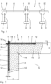
- Component 1 shown comprises a base material, in particular concrete, which is designed in particular as a skeletal structure.
- Component 1 is in particular an existing building.
- the component 1 has a bar 2, which is also referred to as a bar 2 and which runs in particular horizontally.
- the bar 2 is supported on a surface by means of several supports 3.
- the supports 3 are inclined relative to a horizontal direction and are arranged in particular vertically oriented.
- the supports 3 are also referred to as vertical supports or supports 3.
- the component 1 is in particular designed in one piece.
- the supports 3 are connected to one another via the cross member 2. At their end facing away from the bar 2, the supports 3 have a plate-like support element 4.
- the support elements 4 are also referred to as support feet, foundation elements or foundations.
- the crossing areas between the bar 2 and the respective supports 3 are referred to as frame corners. These frame corners each form a discontinuity area 5 of the component 1.
- the discontinuity areas can be L-shaped, T-shaped or cross-shaped.
- Fig. 2 an L-shaped discontinuity region 5 is shown in more detail.
- two drill holes 6 are made in the component 1.
- the drill holes 6 each have a longitudinal axis 7, which are each oriented parallel to the longitudinal extent of the bar 2 or the support 3. Relative to a transverse extension oriented perpendicular to the longitudinal axis 7, the drill holes 6 on the bar 2 and the support 3 are each arranged off-center and in particular in an outer area.
- a respective transverse distance A in the plane oriented perpendicular to the longitudinal axis 7 to the adjacent, outer surface 8 of the Bar 2 or the support 3 is in particular smaller than half of the respective thickness D, in particular A ⁇ 0.4 x D, in particular A ⁇ 0.3 x D, in particular A ⁇ 0.2 x D, in particular A ⁇ 0 .1 x D and in particular A ⁇ 0.05 x D.
- a reinforcing element 9 is arranged in each of the boreholes 6 and anchored twice in the discontinuity region 5.
- the reinforcing element 9 is particularly suitable for transmitting tensile loads.
- the reinforcing element 9 is a tension element.
- the reinforcing element 9 is also suitable for transmitting pressure loads.
- the reinforcing element 9 is a tension/compression element.
- the respective reinforcing element 9 is designed as a reinforcing element in the form of a reinforcing bar, i.e. in particular as a reinforcing steel with an external coarse thread.
- the reinforcing element 9 has a first end 10 and an opposite second end 11.
- the reinforcing element 9 has a first anchoring element 12, which is designed as an external cutting thread. Accordingly, the first anchoring element 12 is formed in one piece on both reinforcing elements 9 and is designed integrally.
- anchoring element 12 made in one piece on the reinforcing element 9 in the form of a self-tapping external thread
- a separate anchoring element 12 which can be coupled to the reinforcing element 9 in a fixed or detachable manner.
- a detachable coupling of the anchoring element 12 with the reinforcing element 9 is particularly advantageously possible with a coupling thread connection, in particular in that the reinforcing element 9 has an external coarse thread has, onto which the anchoring element 12 can be screwed with a corresponding internal thread or attached with a corresponding through hole and fastened by means of a retaining nut.
- a detachable coupling of an internal reinforcing element would be possible, for example, by means of an element that is at least partially sleeve-like.
- a sleeve element can be designed on its outer circumference with a self-tapping external thread and with an inner contour such that it can be coupled to the reinforcing element.
- Such a reinforcing element can, for example, be screwed into the borehole 6 in advance and anchored directly by means of the self-tapping external thread, the reinforcing element then being coupled to the anchoring element 12, 13 anchored in the borehole 6.
- the external cutting thread 12 is designed in such a way that when the reinforcing element 9 is screwed into the borehole 6, it automatically cuts an internal thread in the borehole wall.
- the reinforcing element 9 is automatically and immediately anchored when screwed into the borehole 6.
- the first anchoring element 12 is arranged on the inside.
- the reinforcing element 9 protrudes from the respective borehole 6 with the second end 11 on the surface 8.
- the second end 11 is arranged on the outside of the component 1.
- a second anchoring element 13 is arranged, which has a coupling section having.
- the coupling section is designed in particular as a coupling thread, in particular as a metric thread. It is advantageous if the reinforcing element 9 is designed as a threaded rod and has a metric thread anyway. The formation of a separate coupling section, in particular by rolling on a coupling thread, is then unnecessary. However, the external coarse thread that is already present on the reinforcing element 9 can also serve as a coupling thread.
- the coupling section is in particular formed in one piece and integrally on the reinforcing element 9.
- the fastening nut 14 is screwed onto the second anchoring element 13, in particular the coupling section, and fastened thereto.
- the reinforcing element 9 can be supported and anchored on the second anchoring element 13 on the component 1, in particular on the surface 8.
- a support disk 15 is arranged between the coupling element 14 and the surface 8.
- Fig. 2 the two reinforcing elements 9 are in together Fig. 2 shown. It is understood that the drill holes 6, different from it Fig. 2 suggests, not arranged in one and the same plane and in particular in a direction perpendicular to the plane of the drawing Fig. 2 are arranged spaced apart from each other.
- reinforcing elements 9 in the discontinuity region 5 according to Fig. 2 can be arranged, in particular in different planes, which correspond to a direction perpendicular to the plane of the drawing Fig. 2 are arranged one behind the other.
- anchoring elements 12, 13 can be arranged on the component 1 either on the inside and/or on the outside. It is advantageous if at least one anchoring element is arranged on the inside.
- This intersection area 16 is marked with dots. It is advantageous if the various reinforcing elements 9 extend through the crossing area 16 and in particular protrude on both sides of the crossing area. If the crossing area 16 ends at a surface 8 of the component 1, an external anchoring is in particular arranged in this area. Otherwise, internal anchoring may be advantageous.
- the discontinuity region 5 according to Fig. 3 is essentially cross-shaped or plus-shaped.
- four reinforcing elements 9 are arranged, with two reinforcing elements 9 being assigned to the support 3 and the other two reinforcing elements 9 to the bar 2.
- the drill holes 6 are arranged with their longitudinal axes 7 relative to the longitudinal extents of the bar 2 or the support 3 with an angle of inclination n, which is 20 ° according to the exemplary embodiment shown. Due to the inclined arrangement of the reinforcing elements 9 relative to the respective longitudinal extent of the bar 2 and support 3, it is possible to introduce the reinforcing elements 9 into the discontinuity area 5 and in particular on the bars 2 and supports 3, which are designed as endless components.
- An endless component is understood to mean that the respective Length of bar 2 and support 3 along the longitudinal extent of which is large and in particular is significantly larger than the length of the reinforcing elements 9.
- the longitudinal extent of bar 2 and / or support 3 is each at least twice as large as the length of the reinforcing element 9 arranged therein, in particular five times as large, in particular ten times as large, in particular at least twenty times, in particular at least fifty times as large, in particular at least one hundred times as large. Due to the inclined orientation of the drill holes 6, lateral access for the reinforcing elements 9 into the component 1 is possible.
- the reinforcing elements are arranged symmetrically to one another with respect to the respective longitudinal extent of the bar 2 and support 3. The arrangement can also be asymmetrical.
- the arrangement of the drill holes 6 is in particular such that their vertical projection in the plane of the drawing is in accordance with Fig. 3 cut at a central intersection S.
- the intersection point S denotes a point perpendicular to the drawing plane in Fig. 3 oriented cutting line that intersects reinforcing elements 9 arranged in the different levels.
- the reinforcing elements 9 are arranged in a star shape or radial shape in the discontinuity area 5.
- All reinforcing elements 9 used in the discontinuity region 5 are each designed with two internal anchoring elements 12, 13.
- the reinforcing elements 9 can also be designed with an internal and an external anchoring element or with two external anchoring elements.
- the discontinuity region 5 according to Fig. 4 is T-shaped and essentially represents a combination of the arrangement and design of the reinforcing elements 9 Fig. 2 and 3 represents.
- the reinforcing elements 9 assigned to the bar 2 are as in Fig. 3 arranged inclined.
- the two reinforcing elements 9 assigned to the support 3 are each designed with an internal and an external anchor.
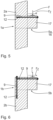
- the component 1a has a carrier 2a with a console 17 molded onto it.
- the carrier 2a is also referred to as a support 2a.
- the console 17 is integrally formed on the support 2a.
- the console 17 defines the crossing area 16 and in particular also the discontinuity area 5a, which extends at least in some areas beyond the console 17 and the crossing area 16 into the support 2a.
- the discontinuity area 5a is in particular larger than the crossing area 16.
- the console 17 serves in particular to absorb an external force F.
- the external force F causes an in Fig. 5 Internal tensile force Fz indicated by dashed lines, which acts on the console and is oriented in a direction transverse and in particular perpendicular to the longitudinal extent of the support 2a.
- the borehole 6 is mounted in the component 1a in such a way that the longitudinal axis 7 is oriented parallel to the line of action of the tensile force Fz.
- the reinforcing element 9 anchored in the borehole 6 has an internal anchoring and an external anchoring.
- the external anchoring is arranged on the exposed surface 8 of the console 17, in particular the surface 8, which is oriented perpendicular to the line of action of the tensile force Fz.
- the external anchoring can also be arranged on the opposite surface 8 of the support 2a. It is also conceivable that the reinforcing element 9 is designed with two internal anchors.
- the reinforcing element 9 is arranged on the outside of the console 17 in such a way that it is arranged adjacent to the surface on which the external force Fz acts.
- a second reinforcing element oriented along the longitudinal direction of the carrier element 2b is additionally attached in the carrier element 2b, in particular with an internal and an external anchoring.
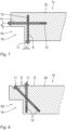
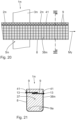
- the component 1c is a bolt 2c with a notch 18, i.e. a recess.
- the cross member 2c is also referred to as a carrier.
- the component 1c is in particular a support element. Due to the notch 18, the component 1c has a discontinuity area 5c.
- the discontinuity region 5c is reinforced by two reinforcing elements 9 oriented along the surfaces of the notch 18.
- the reinforcing elements are arranged on the outside at a distance A with respect to the notch 18.
- the reinforcing elements 9 are each designed with an internal anchor and an external anchor.
- the reinforcing elements 9 can also be designed with exclusively internal anchorings.
- the two reinforcing elements are each arranged on the upper surface 8 of the component 1d and in particular from the upper surface 8 introduced into component 1d.
- This exemplary embodiment is particularly advantageous if access to the component 1d from the side and/or from below is not possible. So that an advantageous absorption of the operating loads is possible, in particular a transverse load, one of the reinforcing elements 9 is arranged inclined relative to the transverse extent of the console.
- the component 1e is designed as a beam or wall element and has a large opening 19 in the form of an opening.
- the opening 19 creates a discontinuity region 5e in the component 1e, in particular laterally and/or above and below the opening 19.
- several reinforcing elements 9 are provided on the component 1e.
- a first group of reinforcing elements 9 each extends in the thickness direction 36 of the component, i.e. perpendicular to the plane of the drawing Fig. 9 .
- four rows of eight reinforcing elements 9 are provided on the front 20 and back 21 of the component 1e. Two rows are arranged above the opening 19 and two rows below the opening 19.
- Each row of reinforcing elements 9 is combined by an external sheet metal strip 22 and mechanically coupled to one another.
- the reinforcing elements 9 are designed with an external anchor.
- the opposite end of the reinforcing elements 9 is designed with an internal anchoring, as shown in particular in Fig. 10 is shown.
- the reinforcing elements of the first group are tension/compression elements and can have continuous anchoring in the structure. With the continuous anchorings, the tension/compression elements can be introduced into the component 1e independently of one another, in particular on the opposite sides 20, 21. It is advantageous if two tension/pressure elements overlap each other, i.e. are arranged overlapping in the thickness direction 36. This ensures that force is transferred from one side, for example the front 20, to the opposite side, for example the back 21.
- the tension/compression elements can be designed with two end anchors.
- the tension/compression elements are anchored at the ends on both sides 20, 21 of the cross section, so that in particular force transmission from one side to the other is possible without overlapping.
- the number of reinforcing elements required is thereby reduced, in particular halved.
- a second group of reinforcing elements 9 comprises tensile elements which are each oriented transversely and in particular perpendicular to the planes which are each defined by the sheet metal strips 22 which combine the reinforcing elements 9 of the first group.
- This second group of reinforcing elements 9 is therefore oriented in the height direction H of the component 1e and on an edge web 23 surrounding the opening 19 Component 1e arranged.
- the reinforcing elements 9 of the second group therefore extend in a direction that is oriented from a bottom 24 to a top 25 of the component 1e.
- the reinforcing elements 9 extend from the bottom 24 in the direction of the opening 19 or from an inner surface of the opening 19 in the direction of the top 25.
- These reinforcing elements are each designed with an internal and an external anchoring and could accordingly also be in the opposite direction , i.e. oriented from the opening 19 to the bottom 24 or oriented from the top 25 to the opening 19.
- the reinforcing elements 9 attached to the front 20 and back 21 have a length such that a free residual cross-section remains between the internal anchors of these reinforcing elements, in which the reinforcing element of the second group is arranged.
- a further reinforcing element 9 is arranged laterally next to the opening 19 and has a length that extends essentially along the entire height H of the component 1e.
- the length of these further reinforcing elements 9 is in particular greater than the height of the opening 19.
- These reinforcing elements 9 extend over the opening 19 and form a lateral border in the height direction H for the opening 19.
- the reinforcing elements 9 of the second group are tension elements and are used in particular to absorb transverse forces.
- the component 1f essentially corresponds to that in Fig. 2 , wherein additional internal reinforcing elements 9 are arranged, which are arranged with an edge distance B adjacent to the inner side surfaces 26.
- B A.
- the component 1f is designed in particular to absorb changing, in particular dynamically changing, loads, which can act on the component 1f, for example as a result of an earthquake.
- Changing loads are understood to be in particular tensile/compressive loads.
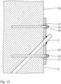
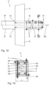
- a beam 27 is fastened in one piece to the support 3g and a ceiling element 28 is arranged thereon.
- the ceiling element 28 has a transverse extension in a direction perpendicular to the plane of the drawing Fig. 12 on which is greater than the transverse extent of the beam and the support 3g.
- a further support 3g is arranged and firmly connected to the ceiling element 28.
- the node element of the component 1g has, at least in some areas, a gradually variable transverse extension due to the ceiling element 28.
- At least one reinforcing element 9 is designed with an external anchor.
- This external anchoring is carried out by means of a mounting unit 29.
- the mounting unit 29 has a mounting plate 30, in particular made of steel material, which is placed on an outer surface 8 of the support 3g and can be fastened and in particular anchored to the support with at least one fastening element 31 .
- the fastening element is in particular a fastening screw which is guided through corresponding openings in the mounting plate and held by a retaining nut 32.
- the reinforcing element 9 is firmly and in particular permanently attached to the mounting plate 30, in particular welded on.
- the reinforcing element 9 and the mounting plate 30 are mounted independently of one another on the support 3g and connected to one another in the arrangement mounted on the support 3, in particular non-positively and/or cohesively, in particular welded to one another.
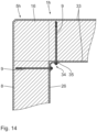
- the component 1h essentially corresponds to a frame corner Fig. 2 , wherein additional surface reinforcement 33 is arranged on both the outer surface 8 and the inner side surface 26.
- the surface reinforcement is designed as textile concrete, which is embedded in particular on the component 1h.
- the surface reinforcement 33 is designed to be flat and enables the component 1h to be clad.
- the component 1h can be clad on one side, on both sides or on all sides.
- the reinforcing elements are each attached starting from the inner side surface 26 and are designed with an external anchor on the inner side surface 26.
- the reinforcing elements 9 are arranged in the component 1h outside the crossing area 16 in the discontinuity area 5h.
- a deflection element 35 is provided, which is held in the area of the external anchoring by means of the reinforcing elements 9.
- the deflection element is designed in particular as an angle plate, in particular corresponding to the concave contour of the component 1h in the corner region 34.
- the deflection element 35 is optional.
- the reinforcing elements can also be designed on the outer surface 8 with the external anchoring.
- the component 1i Either textile concrete or metal sheet serves as surface reinforcement.
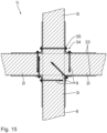
- various arrangements of the reinforcing elements are possible, in particular with an orientation perpendicular to the respective surface of the component 1i, the reinforcing elements being held with an external anchor on which the surface reinforcement 33 and a deflection element 35 in the respective corner area .
- the respective reinforcing element is designed with an internal anchoring.
- a reinforcing element is also conceivable, which is designed with external anchoring on both sides.
- a reinforcing element is provided, which is arranged in the base of the corner region 34 transversely to the intersecting surfaces, in particular oriented at a 45 ° angle. The number of reinforcement elements for attaching the deflection element 35 is thereby reduced.
- the transversely oriented reinforcing element is designed with an internal anchoring, but can alternatively also be designed with two external anchoring elements throughout the node area.
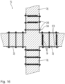
- metal sheets are provided for surface reinforcement, which are held on the component 1j exclusively by reinforcing elements oriented transversely to the surfaces 8.
- the reinforcing elements are either designed as continuous reinforcing elements with two external anchors.
- the reinforcing elements are arranged on the opposite surfaces 8 in such a way that the internal anchoring elements overlap in the thickness direction of the component 1j.
- the overlapping anchoring elements 9 and the respective continuous anchoring elements 9 enable reliable force transmission between the opposing surfaces of the component 1j.
- the advantage of the reinforcing elements 9 with the internal anchoring is that they can be installed more easily.
- the advantage of the continuous reinforcing elements 9 is that a reduced number is required.
- the surface reinforcements 33 are held in the webs by reinforcing elements which are arranged opposite each other and overlap with respect to their anchoring elements.
- Diagonally oriented reinforcing elements are provided in the intersection area 16.
- a reinforcing element is designed throughout with two external anchors. In the perpendicular orientation, two reinforcing elements are provided, which are arranged diagonally across the inner anchoring elements.
- the component 11 has a reinforcement which is designed to absorb torsional stresses in the form of a torsional moment M T.
- the discontinuity region 51 of the component 11 has a component longitudinal axis 37.
- the improved absorption of torsional stresses is ensured in particular by the fact that a first group of reinforcing elements 9 are each arranged parallel to one another and parallel to the longitudinal axis 37 of the component.
- these are reinforcing rods with external coarse threads, with the first anchoring element 12 at the end being designed as a self-tapping external thread and the opposite second anchoring element 13 being designed as a fastening nut.
- the fastening nut is screwed onto a, in particular metric, fastening thread of the reinforcing element 9 and is supported on the outer surface 13 of the component 51.
- the reinforcing elements 9 are arranged with their longitudinal axes 7 at the corner points of a fictitious rectangle.
- the fictitious rectangle is in particular geometrically similar to the outer contour of the component 11.
- the improved absorption of torsional stresses is further made possible in particular by a group of additional reinforcing elements 38.
- the additional reinforcing elements 38 are in particular arranged in pairs opposite one another in a plane perpendicular to the longitudinal axis 37 of the component. In the viewing direction of the component longitudinal axis 37, the additional reinforcing elements 38 form a, in particular closed and in particular rectangular, reinforcing frame, which encloses the first group of reinforcing elements 9.
- the contour of the reinforcing frame is geometrically similar to the outer contour of the component 11.
- the reinforcing frame 39 is arranged in particular close to the surface in the component 11. This means in particular that a surface distance a is small based on the respective edge length s of the component 11.
- the surface distance a defines in particular the vertical distance of a longitudinal axis 40 of the additional reinforcing element 38 from the facing outer surface 8 of the component 11.
- a ⁇ 0.3 ⁇ s in particular a ⁇ 0.25 ⁇ s, in particular a ⁇ 0.2 ⁇ s, in particular a ⁇ 0.15 ⁇ s, in particular a ⁇ 0.1 ⁇ s, in particular a ⁇ 0.05 ⁇ s, and in particular a ⁇ 0.01 ⁇ s.
- the additional reinforcing elements 38 are each designed as concrete screws, the ends of which are anchored in the component 11 with a cutting thread.
- the additional reinforcing elements 38 are attached to the respective surface 8 by means of a fastening nut as a second anchoring element 13.
- the component 1m is designed with reinforcement to absorb torsional stresses.
- the additional reinforcing element 38m is designed as a reinforcing layer which is attached to the surface 8 of the component 1m from the outside.
- the reinforcing layer 38m is in particular designed as a textile concrete with at least one binder layer and a textile, in particular net-like, flexible reinforcement layer integrated and/or embedded therein.
- the reinforcement layer 38m is U-shaped along the outer surface 8 of the component 1m laid out like this in Fig. 21 is shown. At the two ends of the U-contour, the reinforcing layer 38m is attached to the component 1m by means of several reinforcing elements 9 arranged along the longitudinal axis 37 of the component.
- the reinforcing elements 9 are arranged in particular transversely to the longitudinal axis 37 of the component and in particular parallel to one another on opposite side surfaces of the component 1m.
- the reinforcing elements 9 are designed as concrete screws which are anchored internally in the component 1m with a cutting thread. At the opposite, outer end, the reinforcing elements 9 are held by means of a fastening screw.
- a holding strip 41 which is designed in particular as flat steel and has through holes for the reinforcing elements 9.
- two reinforcing elements 9a are present in the component 1m, which extend with the respective longitudinal axis 7 parallel to one another and parallel to the component longitudinal axis 37 in the component 1m.
- the reinforcing elements 9a are optional and can therefore also be omitted.
- the reinforcing elements 9a are based on the cross section of the component 1m Fig. 20 arranged underneath, in particular opposite the open ends of the U of the reinforcing layer 38m and in particular opposite to the reinforcing elements 9, which serve to fasten the reinforcing layer 38m.
- the reinforcing elements 9a are arranged adjacent to the corner regions of the cross section perpendicular to the longitudinal axis 37 of the component.
Abstract
Eine Anordnung umfasst ein mindestens einen Diskontinuitätsbereich (5) aufweisendes Bauteil (1) und mindestens ein Verstärkungselement (9), das zumindest abschnittsweise innerhalb eines Bohrlochs (6) in dem mindestens einen Diskontinuitätsbereich (5) angeordnet und jeweils endseitig verankert ist.

Description
Der Inhalt der deutschen Patentanmeldung
Die Erfindung betrifft eine Anordnung und ein Verfahren zum nachträglichen Verstärken eines Bauteils mit mindestens einem Diskontinuitätsbereich.The invention relates to an arrangement and a method for subsequently reinforcing a component with at least one discontinuity region.
Für die statische Auslegung, also insbesondere die Bemessung und die Konstruktion, von kontinuierlichen Bauteilen gelten Bemessungsregeln, insbesondere erforderliche Biegekraftnachweise und/oder Querkraftnachweise, die auf der Annahme beruhen, dass die Querschnitte in einem Bauteil eben bleiben. Diese Bemessungsregeln sind für Bauteile mit Diskontinuitätsbereichen nicht anwendbar. Diskontinuitätsbereiche sind beispielsweise Rahmenecken, Konsolen und/oder ausgeklinkte Auflager. Ein Diskontinuitätsbereich wird insbesondere durch sprunghafte Querschnittsveränderungen gebildet. Die statische Auslegung eines derartigen Diskontinuitätsbereiches ist insbesondere mit Blick auf die Lebensdauerbewertung oder Lebensdauerberechnung des Bauteils essentiell.For the static design, i.e. in particular the dimensioning and construction, of continuous components, design rules apply, in particular the required bending force verifications and/or shear force verifications, which are based on the assumption that the cross-sections in a component remain flat. These design rules are not applicable to components with discontinuity areas. Areas of discontinuity are, for example, frame corners, consoles and/or notched supports. A discontinuity area is formed in particular by sudden cross-sectional changes. The static design of such a discontinuity area is essential, particularly with regard to the lifespan assessment or lifespan calculation of the component.
Der Erfindung liegt die Aufgabe zugrunde, die statische Auslegung von Bauteilen mit einem Diskontinuitätsbereich zu vereinfachen, insbesondere die Lebensdauerbestimmung für das Bauteil zu verbessern und insbesondere das Bauteil mit einer erhöhten Lebensdauer zuverlässig ausführen zu können.The invention is based on the object of simplifying the static design of components with a discontinuity area, in particular of improving the service life determination for the component and, in particular, of being able to reliably design the component with an increased service life.
Diese Aufgabe ist erfindungsgemäß gelöst, durch eine Anordnung mit den im Anspruch 1 angegebenen Merkmalen sowie durch ein Verfahren mit den im Anspruch 14 angegebenen Merkmalen.This object is achieved according to the invention by an arrangement with the features specified in claim 1 and by a method with the features specified in
Erfindungsgemäß wurde erkannt, dass ein Diskontinuitätsbereich in einem Bauteil vorteilhaft mit einem sogenannten Stabwerksmodell abgebildet werden kann, das Grundlage für die Auslegung, insbesondere für eine statische Bemessung bilden kann. Dadurch ist es möglich, das Tragverhalten des Diskontinuitätsbereichs in Form eines Fachwerks zu modellieren. Das Fachwerk umfasst Zugstreben und Druckstreben. Es wurde gefunden, dass mit einem derartigen Stabwerksmodell ein reales Bauteil, das insbesondere als Verbundbauteil und insbesondere als Bestandsbauwerk aus Stahlbeton ausgeführt ist, vorteilhaft modelliert werden kann. Druckstreben können von einem Grundmaterial des Bauteils, insbesondere Beton, abgebildet werden. Zugstreben können durch separate Verstärkungselemente abgebildet werden. Ein derartiges Verstärkungselement ist insbesondere Bewehrungselement und insbesondere eine Bewehrungsstange, die auch als Bewehrungsstahl, Betonstahl oder Armierungseisen bezeichnet wird. Das mindestens eine Verstärkungselement ist insbesondere ein Zug-/Druckelement. Das Stabwerksmodell ermöglicht es, Zugstreben zu identifizieren, die insbesondere in einem Bestandstragwerk keine ausreichende Festigkeit aufweisen und/oder geschädigt sind. Derart identifizierte Zugstreben können gezielt ersetzt oder durch neue Zugstreben ergänzt werden, um die Tragfähigkeit und die Gebrauchstauglichkeit des Diskontinuitätsbereichs wiederherzustellen und/oder zu steigern. Ein weiterer Vorteil der Erfindung besteht darin, dass Überbeanspruchungen der Druckstreben, insbesondere der Betonstreben, erkannt und beseitigt werden können. Verstärkungselemente können zur gezielten Verstärkung der Druckstreben, insbesondere nachträglich, eingebracht werden.According to the invention, it was recognized that a discontinuity area in a component can advantageously be depicted with a so-called framework model, which can form the basis for the design, in particular for a static dimensioning. This makes it possible to model the load-bearing behavior of the discontinuity area in the form of a truss. The truss includes tension struts and compression struts. It was found that with such a framework model, a real component, which is designed in particular as a composite component and in particular as an existing structure made of reinforced concrete, can be advantageously modeled. Compression struts can be made from a base material of the component, in particular concrete. Tension struts can be created using separate reinforcing elements. Such a reinforcing element is in particular a reinforcing element and in particular a reinforcing bar, which is also referred to as reinforcing steel, reinforcing steel or reinforcing iron. The at least one reinforcing element is in particular a tension/compression element. The framework model makes it possible to identify tension struts that do not have sufficient strength, particularly in an existing structure have and/or are damaged. Tension struts identified in this way can be specifically replaced or supplemented with new tension struts in order to restore and/or increase the load-bearing capacity and usability of the discontinuity area. A further advantage of the invention is that overstressing of the compression struts, in particular the concrete struts, can be detected and eliminated. Reinforcing elements can be introduced to specifically reinforce the pressure struts, especially subsequently.
Das Verstärkungselement kann ursprünglich in dem Bauteil als Bewehrungselement vorhanden sein, insbesondere in dem Grundmaterial, insbesondere Beton, eingegossen. Das Verstärkungselement kann zusätzlich oder alternativ nachträglich in das Grundmaterial, also in den Beton, eingebracht worden sein, insbesondere in ein Bohrloch, das zumindest teilweise innerhalb des Diskontinuitätsbereichs angeordnet ist. Der Diskontinuitätsbereich ist insbesondere beidseitig einer sprunghaften Querschnittsveränderung ausgebildet. Das Verstärkungselement ist insbesondere jeweils endseitig verankert. Wenn das Verstärkungselement initial in dem Grundmaterial eingebettet worden ist, ist es per se endseitig verankert.The reinforcing element can originally be present in the component as a reinforcing element, in particular cast in the base material, in particular concrete. The reinforcing element can additionally or alternatively have been subsequently introduced into the base material, i.e. into the concrete, in particular into a borehole which is at least partially arranged within the discontinuity area. The discontinuity region is formed in particular on both sides of a sudden cross-sectional change. The reinforcing element is in particular anchored at each end. If the reinforcing element has initially been embedded in the base material, it is per se anchored at the end.
Erfindungsgemäß ist die nachträgliche Verstärkung eines Bauteils mit Diskontinuitätsbereich besonders vorteilhaft, wenn das Bauteil ein Bestandsbauwerk aus Beton und insbesondere aus Stahlbeton ist. Das Bauteil kann aber auch aus anderen Materialien hergestellt sein, insbesondere aus Stein, Mauerwerk, Holz und/oder Kunststoff.According to the invention, the subsequent reinforcement of a component with a discontinuity area is particularly advantageous if the component is an existing structure made of concrete and in particular reinforced concrete. However, the component can also be made from other materials, in particular stone, masonry, wood and/or plastic.
Es wurde gefunden, dass mit einem nachträglich eingebrachten Verstärkungselement der Diskontinuitätsbereich und damit das Bauteil insgesamt stabilisiert, also verstärkt werden kann. Die Lebensdauer eines derartigen Bauteils ist erhöht. Ein Austausch und/oder eine Neuherstellung eines derartigen Bauteils kann hinausgezögert und insbesondere verhindert werden. Ein derartiges Verfahren ist kosteneffizient und nachhaltig, also ökonomisch und ökologisch sinnvoll.It was found that with a subsequently introduced reinforcing element, the discontinuity area and thus the component as a whole can be stabilized, i.e. strengthened. The lifespan of such a Component is increased. An exchange and/or a new production of such a component can be delayed and in particular prevented. Such a process is cost-efficient and sustainable, i.e. economically and ecologically sensible.
Das Verstärkungselement ist insbesondere stabförmig oder stangenförmig ausgeführt und weist insbesondere eine lineare Längsachse auf. An den beiden gegenüberliegenden Stirnseiten ist vorteilhaft eine Verankerung in dem Bauteil möglich. Die Anbringung und Verankerung des Verstärkungselements in dem Bauteil ist unkompliziert und effizient möglich. Die Verstärkung des Bauteils ist unaufwändig.The reinforcing element is in particular rod-shaped or rod-shaped and in particular has a linear longitudinal axis. Anchoring in the component is advantageously possible on the two opposite end faces. Attaching and anchoring the reinforcing element in the component is uncomplicated and efficient. Reinforcing the component is inexpensive.
Eine Ausführung des Verstärkungselements gemäß Anspruch 2 ist insbesondere für die Anwendung in einem Betonbauteil vorteilhaft. Das Verstärkungselement ist insbesondere als standardisiertes Massenprodukt kosteneffizient, mit definierter Geometrie und genormter Festigkeit verfügbar. Ein derartiges Verstärkungselement ist robust und weist eine hohe Zuverlässigkeit auf. Das Verstärkungselement ermöglicht eine zuverlässige und nachvollziehbare Verstärkung des Bauteils. Ein derart verstärktes Bauteil weist eine vorhersagbare Festigkeit und Stabilität auf.An embodiment of the reinforcing element according to
Eine Anordnung gemäß Anspruch 3 vereinfacht die Verankerung in dem Bohrloch.An arrangement according to
Eine Ausgestaltung des Verstärkungselements gemäß Anspruch 4 ermöglicht die unmittelbare Verankerung im Bohrloch.An embodiment of the reinforcing element according to
Eine Anordnung gemäß Anspruch 5 ermöglicht eine flexible Verankerung des Verstärkungselements mittels eines Koppelelements.An arrangement according to
Eine Anordnung gemäß Anspruch 6 ermöglicht eine innenliegend angeordnete und geschützte Verankerung des Verstärkungselements in dem Bauteil.An arrangement according to
Eine Anordnung gemäß Anspruch 7 ermöglicht eine flexible Verstärkung des Bauteils. Eine Anordnung des zweiten Verankerungselements vollständig innerhalb des Bohrlochs ermöglicht eine geschützte und insbesondere optisch ansprechend, weil versteckte Anordnung.An arrangement according to
Eine außenliegende Verankerung des zweiten Verankerungselements, insbesondere derart, dass es an einer das Bohrloch angrenzenden Oberfläche des Bauteils abgestützt ist, vereinfacht die Zugänglichkeit und die Montage des zweiten Verankerungselements. Insbesondere ist eine nachträgliche Lösbarkeit des Verstärkungselements mit einer außenliegenden Verankerung vereinfacht. Eine Abstützung des zweiten Verankerungselements an der Oberfläche kann insbesondere mittels eines Koppelelements erfolgen, das mechanisch mit dem Verstärkungselement koppelbar ist. Das Koppelelement ist beispielsweise eine Schraubmutter, die auf das Verstärkungselement aufschraubbar ist. In diesem Fall weist das zweite Verankerungselement insbesondere ein Koppelgewinde, insbesondere ein metrisches Außengewinde oder ein Außengrobgewinde auf.An external anchoring of the second anchoring element, in particular in such a way that it is supported on a surface of the component adjacent to the borehole, simplifies the accessibility and assembly of the second anchoring element. In particular, subsequent releasability of the reinforcing element is simplified with an external anchoring. The second anchoring element can be supported on the surface in particular by means of a coupling element that can be mechanically coupled to the reinforcing element. The coupling element is, for example, a screw nut that can be screwed onto the reinforcing element. In this case, the second anchoring element has in particular a coupling thread, in particular a metric external thread or a coarse external thread.
Eine Anordnung gemäß Anspruch 8 ermöglicht eine verbesserte, insbesondere erhöhte, Tragwirkung der verstärkten Anordnung. Eine Oberflächenbewehrung ist insbesondere flächenhaft an der Oberfläche des Bauteils angeordnet und daran befestigt, insbesondere eingebettet. Als besonders vorteilhaft hat sich eine Oberflächenbewehrung in Form von Textilbeton erwiesen. Insbesondere ist es vorteilhaft, wenn die Oberflächenbewehrung mechanisch mit dem Verstärkungselement gekoppelt ist. Die Festigkeit ist dadurch zusätzlich erhöht. Die Oberflächenbewehrung ist insgesamt mittels des Verstärkungselements am Bauteil befestigt. Zusätzlich oder alternativ kann Textilbeton als Teil einer Verbundlage integriert am Bauteil ausgeführt sein. Eine separate Befestigung mittels des Verstärkungselements kann entbehrlich sein. Als Oberflächenbewehrung kann auch ein plattenartiges Element, insbesondere eine Metallplatte, insbesondere eine Stahlplatte dienen. Insbesondere können mehrere flächenartige Elemente miteinander verbunden sein, beispielsweise zu einem Winkel-Profilelement und/oder zu einem den ursprünglichen Querschnitt umschließenden Element. Die Oberflächenbewehrung kann formstabil oder biegeschlaff ausgeführt sein.An arrangement according to
Eine Anordnung gemäß Anspruch 9 weist eine zusätzlich erhöhte Festigkeit auf, insbesondere in einem Eckenbereich des Bauteils. Insbesondere in einem konkaven Bereich des Bauteils ist mittels eines Umlenkelements die zielgerichtete Umlenkung der Oberflächenbewehrung an der Oberfläche des Bauteils sichergestellt. Zudem ist die zuverlässige, insbesondere flächenhafte, Anlage der Oberflächenbewehrung an der Oberfläche des Bauteils gewährleistet. Unerwünschte Zwischenräume zwischen der Oberflächenbewehrung und der Oberfläche des Bauteils können reduziert und insbesondere verhindert werden.An arrangement according to
Eine Anordnung gemäß Anspruch 10 ermöglicht eine stabile, also mechanisch robuste, und unaufwändig herstellbare außenliegende Verstärkung. Das mindestens eine Verstärkungselement ist an einer Halteplatte befestigt und insbesondere daran angeschweißt. Die Halteplatte wird an der Oberfläche des Bauteils befestigtAn arrangement according to
Eine Anordnung gemäß Anspruch 11 ermöglicht eine verbesserte Aufnahme von Torsionsbeanspruchungen, die insbesondere bezüglich einer Bauteil-Längsachse des mindestens einen Diskontinuitätsbereichs wirken.An arrangement according to
Eine Anordnung gemäß Anspruch 12 gewährleistet eine unkomplizierte Aufnahme der Torsionsbeanspruchungen, insbesondere ohne zusätzliche Bauteile und insbesondere ausschließlich durch geeignete Anordnung mehrerer Zusatz-Verstärkungselemente, insbesondere in Form von Betonschrauben und/oder durchgängig angeordneten Gewindestangen.An arrangement according to
Eine Anordnung gemäß Anspruch 13 ermöglicht eine großflächige Verstärkung, die insbesondere für besonders große Bauteile vorteilhaft ist.An arrangement according to
Ein Verfahren gemäß Anspruch 14 weist im Wesentlichen die Vorteile der Anordnung gemäß Anspruch 1 auf. Besonders vorteilhaft ist es, dass ein Verstärkungselement insbesondere nachträglich an einem bereits existierenden Bauteil angebracht und der Diskontinuitätsbereich des Bauteils und deshalb das Bauteil insgesamt mechanisch verstärkt wird.A method according to claim 14 essentially has the advantages of the arrangement according to claim 1. It is particularly advantageous that a reinforcing element is attached, in particular subsequently, to an already existing component and the discontinuity region of the component and therefore the component as a whole is mechanically reinforced.
Sowohl die in den Patentansprüchen angegebenen Merkmale als auch die in der nachfolgenden Beschreibung von Ausführungsbeispielen der erfindungsgemäßen Anordnung angegebenen Merkmale sind jeweils für sich alleine oder in Kombination miteinander geeignet, den erfindungsgemäßen Gegenstand weiterzubilden. Die jeweiligen Merkmalskombinationen stellen hinsichtlich der Weiterbildungen des Erfindungsgegenstandes keine Einschränkung dar, sondern weisen im Wesentlichen lediglich beispielhaften Charakter auf.Both the features specified in the patent claims and the features specified in the following description of exemplary embodiments of the arrangement according to the invention are each suitable, alone or in combination with one another, for further developing the subject matter according to the invention. The respective combinations of features do not represent any restrictions with regard to the developments of the subject matter of the invention, but are essentially only of an exemplary nature.
Zusätzliche Merkmale, vorteilhafte Ausgestaltungen und Einzelheiten der Erfindung ergeben sich aus der nachfolgenden Beschreibung von Ausführungsbeispielen anhand der Zeichnung. Es zeigen:
- Fig. 1
- eine schematische Darstellung eines Bauteils mit Diskontinuitätsbereichen,
- Fig. 2
- eine vergrößerte, geschnittene Darstellung des Details II in
Fig. 1 , - Fig. 3
- eine vergrößerte, geschnittene Darstellung des Details III in
Fig. 1 , - Fig. 4
- eine vergrößerte, geschnittene Darstellung des Details IV in
Fig. 1 , - Fig. 5
- eine
Fig. 2 entsprechende Darstellung einer Konsolverstärkung, - Fig. 6
- eine
Fig. 2 entsprechende Darstellung einer weiteren Konsolverstärkung, - Fig. 7
- eine
Fig. 2 entsprechende Darstellung einer Verstärkung an einem ausgeklinkten Auflager, - Fig. 8
- eine
Fig. 7 entsprechende Darstellung mit einer alternativen Anordnung der Verstärkungselemente, - Fig. 9
- eine Seitenansicht eines Bauteils mit einem Diskontinuitätsbereich in Form einer Öffnung,
- Fig. 10
- eine Schnittdarstellung gemäß Schnittlinie X-X in
Fig. 9 , - Fig. 11
- eine
Fig. 2 entsprechende Darstellung einer Anordnung für wechselnde Beanspruchungen, - Fig. 12
- eine
Fig. 3 entsprechende Darstellung einer Knotenverstärkung mit einer Stütze einer Decke und einem Unterzug, - Fig. 13
- eine vergrößerte Detaildarstellung des Details XIII in
Fig. 12 , - Fig. 14
- eine
Fig. 2 entsprechende Darstellung mit einer Oberflächenbewehrung und einem Umlenkelement, - Fig. 15
- eine
Fig. 3 entsprechende Darstellung mit Oberflächenbewehrungen und Umlenkelementen, - Fig. 16
- eine
Fig. 15 entsprechende Darstellung mit einer Oberflächenbewehrung in Form von Metallblechen, - Fig. 17
- eine
Fig. 16 entsprechende Darstellung mit diagonal angeordneten Verstärkungselementen, - Fig. 18
- eine
Fig. 3 entsprechende Schnittdarstellung mit mehreren ZusatzVerstärkungselementen, die senkrecht zu einer Bauteil-Längsachse des mindestens einen Diskontinuitätsbereichs angeordnet sind, - Fig. 19
- eine Schnittdarstellung gemäß Schnittlinie XIX-XIX in
Fig. 18 , - Fig. 20
- eine
Fig. 18 entsprechende Seitenansicht eines Bauteils mit einer außenliegenden Verstärkungslage, - Fig. 21
- eine Schnittdarstellung gemäß Schnittlinie XXI-XXI in
Fig. 20 .
- Fig. 1
- a schematic representation of a component with discontinuity areas,
- Fig. 2
- an enlarged, sectioned view of detail II in
Fig. 1 , - Fig. 3
- an enlarged, sectioned view of detail III in
Fig. 1 , - Fig. 4
- an enlarged, sectioned representation of detail IV in
Fig. 1 , - Fig. 5
- one
Fig. 2 corresponding representation of a console reinforcement, - Fig. 6
- one
Fig. 2 corresponding representation of further console reinforcement, - Fig. 7
- one
Fig. 2 corresponding representation of a reinforcement on a notched support, - Fig. 8
- one
Fig. 7 corresponding representation with an alternative arrangement of the reinforcing elements, - Fig. 9
- a side view of a component with a discontinuity area in the form of an opening,
- Fig. 10
- a sectional view according to section line XX in
Fig. 9 , - Fig. 11
- one
Fig. 2 corresponding representation of an arrangement for changing stresses, - Fig. 12
- one
Fig. 3 corresponding representation of a node reinforcement with a support of a ceiling and a beam, - Fig. 13
- an enlarged detailed view of detail XIII in
Fig. 12 , - Fig. 14
- one
Fig. 2 corresponding representation with surface reinforcement and a deflection element, - Fig. 15
- one
Fig. 3 corresponding representation with surface reinforcements and deflection elements, - Fig. 16
- one
Fig. 15 corresponding representation with surface reinforcement in the form of metal sheets, - Fig. 17
- one
Fig. 16 corresponding representation with diagonally arranged reinforcing elements, - Fig. 18
- one
Fig. 3 corresponding sectional view with several additional reinforcing elements which are arranged perpendicular to a component longitudinal axis of the at least one discontinuity region, - Fig. 19
- a sectional view according to section line XIX-XIX in
Fig. 18 , - Fig. 20
- one
Fig. 18 corresponding side view of a component with an external reinforcement layer, - Fig. 21
- a sectional view according to section line XXI-XXI in
Fig. 20 .
Ein in
In
In den Bohrlöchern 6 ist jeweils ein Verstärkungselement 9 angeordnet und in dem Diskontinuitätsbereich 5 zweifach verankert. Das Verstärkungselement 9 ist insbesondere zur Übertragung von Zuglasten geeignet. Das Verstärkungselement 9 ist ein Zugelement. Grundsätzlich ist das Verstärkungselement 9 auch zur Übertragung von Drucklasten geeignet. Allgemein ist das Verstärkungselement 9 ein Zug-/Druckelement.A reinforcing
Das jeweilige Verstärkungselement 9 ist als Bewehrungselement in Form einer Bewehrungsstange ausgeführt, also insbesondere als Betonstahl mit einem Außengrobgewinde. Das Verstärkungselement 9 weist ein erstes Ende 10 und ein gegenüberliegendes zweites Ende 11 auf. An dem jeweils ersten Ende 10 weist das Verstärkungselement 9 ein erstes Verankerungselement 12 auf, das als Außenschneidgewinde ausgeführt ist. Entsprechend ist das erste Verankerungselement 12 bei beiden Verstärkungselementen 9 jeweils einteilig angeformt und integral ausgeführt.The respective reinforcing
Anstelle des einteilig am Verstärkungselement 9 ausgeführten Verankerungselements 12 in Form eines selbstschneidenden Außengewindes ist es auch möglich, ein separates Verankerungselement 12 vorzusehen, das fest oder lösbar mit dem Verstärkungselement 9 koppelbar ist. Eine lösbare Kopplung des Verankerungselements 12 mit dem Verstärkungselement 9 ist besonders vorteilhaft mit einer Koppel-Gewindeverbindung möglich, insbesondere indem das Verstärkungselement 9 ein Außengrobgewinde aufweist, auf das das Verankerungselement 12 mit einem korrespondierenden Innengewinde aufschraubbar oder mit einer entsprechenden Durchgangsbohrung aufsteckbar und mittels einer Haltemutter befestigbar ist.Instead of the anchoring
Eine lösbare Kopplung eines innenliegenden Verstärkungselements wäre beispielsweise durch ein zumindest abschnittsweise hülsenartiges Element möglich. Ein derartiges Hülsenelement kann an seinem Außenumfang mit einem selbstschneidenden Außengewinde und mit einer Innenkontur derart ausgeführt sein, dass es mit dem Verstärkungselement koppelbar ist. Ein derartiges Verstärkungselement kann beispielsweise vorab in das Bohrloch 6 eingedreht und mittels des selbstschneidenden Außengewindes unmittelbar verankert werden, wobei das Verstärkungselement anschließend mit dem im Bohrloch 6 verankerten Verankerungselement 12, 13 gekoppelt wird. Alternativ ist es möglich, das Verankerungselement 12, 13 vorab mit dem Verstärkungselement 9, also außerhalb des Bohrlochs 6, lösbar oder unlösbar zu koppeln und anschließend in der gekoppelten Anordnung in das Bohrloch 6 einzudrehen und dort zu verankern.A detachable coupling of an internal reinforcing element would be possible, for example, by means of an element that is at least partially sleeve-like. Such a sleeve element can be designed on its outer circumference with a self-tapping external thread and with an inner contour such that it can be coupled to the reinforcing element. Such a reinforcing element can, for example, be screwed into the
Das Außenschneidgewinde 12 ist derart ausgeführt, dass es beim Eindrehen des Verstärkungselements 9 in das Bohrloch 6 automatisch ein Innengewinde in der Bohrlochwandung schneidet. Das Verstärkungselement 9 ist beim Eindrehen in das Bohrloch 6 automatisch und unmittelbar verankert. Das erste Verankerungselement 12 ist innenlegend angeordnet.The
Das Verstärkungselement 9 ragt mit dem zweiten Ende 11 an der Oberfläche 8 aus dem jeweiligen Bohrloch 6 vor. Das zweite Ende 11 ist bezüglich des Bauteils 1 außenliegend angeordnet. An dem zweiten Ende 11 ist ein zweites Verankerungselement 13 angeordnet, das einen Koppelabschnitt aufweist. Der Koppelabschnitt ist insbesondere als Koppelgewinde, insbesondere als metrisches Gewinde ausgeführt. Vorteilhaft ist es, wenn das Verstärkungselement 9 als Gewindestange ausgeführt ist und ein metrisches Gewinde ohnehin aufweist. Die Ausbildung eines separaten Koppelabschnitts, insbesondere durch Aufwalzen eines Koppelgewindes, ist dann entbehrlich. Als Koppelgewinde kann aber auch das an dem Verstärkungselement 9 ohnehin vorhandene Außengrobgewinde dienen. Der Koppelabschnitt ist insbesondere einteilig und integral an dem Verstärkungselement 9 angeformt. Mit dem Koppelabschnitt wirkt ein, insbesondere separat ausgeführtes Koppelelement 14 zusammen, das gemäß dem gezeigten Ausführungsbeispiel als Befestigungsmutter 14 ausgeführt ist. Die Befestigungsmutter 14 wird an dem zweiten Verankerungselement 13, insbesondere dem Koppelabschnitt, aufgeschraubt und daran befestigt. Mit dem Koppelelement 14 kann das Verstärkungselement 9 am zweiten Verankerungselement 13 an dem Bauteil 1, insbesondere an der Oberfläche 8 abgestützt und verankert werden. Gemäß dem gezeigten Ausführungsbeispiel ist zwischen dem Koppelelement 14 und der Oberfläche 8 eine Stützscheibe 15 angeordnet.The reinforcing
Allein aus Darstellungsgründen sind die beiden Verstärkungselemente 9 gemeinsam in
Es können mehr als zwei Verstärkungselemente 9 in dem Diskontinuitätsbereich 5 gemäß
Es versteht sich, dass die Verankerungselemente 12, 13 an dem Bauteil 1 entweder innenliegend und/oder außenliegend angeordnet sein können. Vorteilhaft ist es, wenn zumindest ein Verankerungselement innenliegend angeordnet ist.It goes without saying that the anchoring
Wesentlich ist, dass sich der Riegel 2 und die Stütze 3 kreuzen. Dieser Kreuzungsbereich 16 ist gepunktet gekennzeichnet. Vorteilhaft ist es, wenn sich die verschiedenen Verstärkungselemente 9 durch den Kreuzungsbereich 16 hindurch erstrecken und insbesondere beidseitig an dem Kreuzungsbereich überstehen. Wenn der Kreuzungsbereich 16 an einer Oberfläche 8 des Bauteils 1 endet, ist in diesem Bereich insbesondere eine außenliegende Verankerung angeordnet. Andernfalls kann eine innenliegende Verankerung vorteilhaft sein.It is important that the
Der Diskontinuitätsbereich 5 gemäß
Die Bohrlöcher 6 sind mit ihren Längsachsen 7 jeweils gegenüber den Längserstreckungen des Riegels 2 bzw. der Stütze 3 mit einem Neigungswinkel n angeordnet, der gemäß dem gezeigten Ausführungsbeispiel 20° beträgt. Durch die geneigte Anordnung der Verstärkungselemente 9 gegenüber der jeweiligen Längserstreckung von Riegel 2 und Stütze 3 gelingt es, die Verstärkungselemente 9 in den Diskontinuitätsbereich 5 und insbesondere an den als Endloskomponenten ausgeführten Riegeln 2 und Stützen 3 einzubringen. Als Endloskomponente wird verstanden, dass die jeweilige Länge von Riegel 2 und Stütze 3 entlang deren Längserstreckung groß ist und insbesondere deutlich größer ist als die Länge der Verstärkungselemente 9. Insbesondere ist die Längserstreckung von Riegel 2 und/oder Stütze 3 jeweils mindestens doppelt so groß wie die Länge des darin angeordneten Verstärkungselements 9, insbesondere fünfmal so groß, insbesondere zehnmal so groß, insbesondere mindestens zwanzigmal, insbesondere mindestens fünfzigmal so groß, insbesondere mindestens einhundertmal so groß. Aufgrund der geneigten Orientierung der Bohrlöcher 6 ist ein seitlicher Zugang für die Verstärkungselemente 9 in das Bauteil 1 möglich. Die Verstärkungselemente sind bezüglich der jeweiligen Längserstreckung von Riegel 2 und Stütze 3 symmetrisch zueinander angeordnet. Die Anordnung kann auch unsymmetrisch sein.The drill holes 6 are arranged with their
Die Anordnung der Bohrlöcher 6 ist insbesondere derart, dass sich deren senkrechte Projektion in der Zeichenebene gemäß
Sämtliche in dem Diskontinuitätsbereich 5 verwendeten Verstärkungselemente 9 sind jeweils mit zwei innenliegenden Verankerungselementen 12, 13 ausgeführt. Die Verstärkungselemente 9 können auch mit einem innenliegenden und einem außenliegenden Verankerungselement oder mit zwei außenliegenden Verankerungselementen ausgeführt sein.All reinforcing
Der Diskontinuitätsbereich 5 gemäß
Die dem Riegel 2 zugeordneten Verstärkungselemente 9 sind wie in
Im Folgenden wird unter Bezugnahme auf
Das Bauteil 1a weist einen Träger 2a mit einer daran angeformten Konsole 17 auf. Der Träger 2a wird auch als Stütze 2a bezeichnet. Die Konsole 17 ist einteilig an der Stütze 2a angeformt. Die Konsole 17 definiert den Kreuzungsbereich 16 und insbesondere auch den Diskontinuitätsbereich 5a, der sich über die Konsole 17 und den Kreuzungsbereich 16 hinaus in die Stütze 2a zumindest bereichsweise erstreckt. Der Diskontinuitätsbereich 5a ist insbesondere größer als der Kreuzungsbereich 16. Die Konsole 17 dient insbesondere dazu, eine äußere Kraft F aufzunehmen. Die äußere Kraft F bewirkt eine in
Zur Verstärkung der Konsole 17 ist das Bohrloch 6 in dem Bauteil 1a derart angebracht, dass die Längsachse 7 parallel zur Wirkungslinie der Zugkraft Fz orientiert ist. Das in dem Bohrloch 6 verankerte Verstärkungselement 9 weist eine innenliegende Verankerung und eine außenliegende Verankerung auf. Gemäß dem gezeigten Ausführungsbeispiel ist die außenliegende Verankerung an der freiliegenden Oberfläche 8 der Konsole 17 angeordnet, insbesondere der Oberfläche 8, die senkrecht zur Wirkungslinie der Zugkraft Fz orientiert ist.To reinforce the
Alternativ kann die außenliegende Verankerung auch an der gegenüberliegenden Oberfläche 8 der Stütze 2a angeordnet sein. Es ist auch denkbar, dass das Verstärkungselement 9 mit zwei innenliegenden Verankerungen ausgeführt ist.Alternatively, the external anchoring can also be arranged on the
Entsprechend der Ausgestaltung des Diskontinuitätsbereichs 5 in
Im Folgenden wird unter Bezugnahme auf
Im Unterschied zu der Konsole gemäß
Im Folgenden wird unter Bezugnahme auf
Das Bauteil 1c ist ein Riegel 2c mit einer Ausklinkung 18, also einer Ausnehmung. Der Querträger 2c wird auch als Träger bezeichnet. Das Bauteil 1c ist insbesondere ein Auflagerelement. Aufgrund der Ausklinkung 18 weist das Bauteil 1c einen Diskontinuitätsbereich 5c auf. Der Diskontinuitätsbereich 5c wird durch zwei entlang der Oberflächen der Ausklinkung 18 orientierten Verstärkungselemente 9 verstärkt. Die Verstärkungselemente sind bezüglich der Ausklinkung 18 außenliegend mit dem Abstand A angeordnet. Der Verstärkungselemente 9 sind jeweils mit einer inneren Verankerung und einer außenliegenden Verankerung ausgeführt. Die Verstärkungselemente 9 können auch mit ausschließlich innenliegenden Verankerungen ausgeführt sein.The
Bei dem Ausführungsbeispiel 1d, das ebenfalls ein ausgeklinktes Auflager zeigt, sind die beiden Verstärkungselemente jeweils an der oberen Oberfläche 8 des Bauteils 1d angeordnet und insbesondere von der oberen Oberfläche 8 in das Bauteil 1d eingebracht. Dieses Ausführungsbeispiel ist insbesondere dann vorteilhaft, wenn ein Zugang von der Seite und/oder von unten an das Bauteil 1d nicht möglich ist. Damit eine vorteilhafte Aufnahme der Betriebslasten möglich ist, insbesondere eine Querbeanspruchung ist eines der Verstärkungselemente 9 gegenüber der Quererstreckung der Konsole geneigt angeordnet.In the
Im Folgenden wird unter Bezugnahme auf
Das Bauteil 1e ist als Balken oder Wandelement ausgeführt und weist eine großflächige Öffnung 19 in Form eines Durchbruchs auf. Die Öffnung 19 bewirkt in dem Bauteil 1e einen Diskontinuitätsbereich 5e, insbesondere seitlich und/oder oberhalb und unterhalb der Öffnung 19. Zur Verstärkung dieses Diskontinuitätsbereichs 5e sind an dem Bauteil 1e mehrere Verstärkungselemente 9 vorgesehen.The
Eine erste Gruppe von Verstärkungselementen 9 erstreckt sich jeweils in Dickenrichtung 36 des Bauteils, also senkrecht zur Zeichenebene in
Die Verstärkungselemente der ersten Gruppe sind Zug-/Druckelemente und können eine kontinuierliche Verankerung im Tragwerk aufweisen. Bei den kontinuierlichen Verankerungen können die Zug-/Druckelemente unabhängig voneinander, insbesondere an den gegenüberliegenden Seiten 20, 21 in das Bauteil 1e eingebracht werden. Vorteilhaft ist es, wenn jeweils zwei Zug-/Druckelemente sich wechselseitig übergreifen, also in Dickenrichtung 36 überlappend angeordnet sind. Damit ist ein Kraftübertrag von der einen Seite, beispielsweise der Vorderseite 20, auf die gegenüberliegende Seite, beispielsweise die Rückseite 21, sichergestellt.The reinforcing elements of the first group are tension/compression elements and can have continuous anchoring in the structure. With the continuous anchorings, the tension/compression elements can be introduced into the
Alternativ können die Zug-/Druckelemente mit zwei Endverankerungen ausgeführt sein. Die Zug-/Druckelemente werden an beiden Seiten 20, 21 des Querschnitts endseitig verankert, sodass insbesondere eine Kraftübertragung von der einen auf die andere Seite ohne Übergreifung ermöglicht ist. Die Anzahl der benötigten Verstärkungselemente ist dadurch reduziert, insbesondere halbiert.Alternatively, the tension/compression elements can be designed with two end anchors. The tension/compression elements are anchored at the ends on both
Eine zweite Gruppe von Verstärkungselementen 9 umfasst Zugelemente, die jeweils quer und insbesondere senkrecht zu den Ebenen orientiert sind, die jeweils von den Blechstreifen 22, die die Verstärkungselemente 9 der ersten Gruppe zusammenfassen, festgelegt werden. Diese zweite Gruppe der Verstärkungselemente 9 ist also in Höhenrichtung H des Bauteils 1e orientiert und an einem die Öffnung 19 umgebenden Randsteg 23 an dem Bauteil 1e angeordnet. Die Verstärkungselemente 9 der zweiten Gruppe erstrecken sich also in einer Richtung, die orientiert ist von einer Unterseite 24 zu einer Oberseite 25 des Bauteils 1e. Die Verstärkungselemente 9 erstrecken sich gemäß dem gezeigten Ausführungsbeispiel von der Unterseite 24 in Richtung der Öffnung 19 oder von einer Innenfläche der Öffnung 19 in Richtung der Oberseite 25. Diese Verstärkungselemente sind jeweils mit einer innenliegenden und einer außenliegenden Verankerung ausgeführt und könnten entsprechend auch in umgekehrter Richtung, also von der Öffnung 19 zur Unterseite 24 hin orientiert oder von der Oberseite 25 zur Öffnung 19 hin orientiert angeordnet sein.A second group of reinforcing
Die an der Vorderseite 20 und Rückseite 21 angebrachten Verstärkungselemente 9 weisen eine Länge derart auf, dass zwischen den innenliegenden Verankerungen dieser Verstärkungselemente ein freier Restquerschnitt verbleibt, in dem das Verstärkungselement der zweiten Gruppe angeordnet ist.The reinforcing
Jeweils seitlich neben der Öffnung 19 ist ein weiteres Verstärkungselement 9 angeordnet, das eine Länge derart aufweist, die sich im Wesentlichen entlang der gesamten Höhe H des Bauteils 1e erstreckt. Die Länge dieser weiteren Verstärkungselemente 9 ist insbesondere größer als die Höhenerstreckung der Öffnung 19. Diese Verstärkungselemente 9 übergreifen die Öffnung 19 und bilden eine seitliche Einfassung in Höhenrichtung H für die Öffnung 19.A further reinforcing
Die Verstärkungselemente 9 der zweiten Gruppe sind Zugelemente und dienen insbesondere zur Aufnahme von Querkräften.The reinforcing
Im Folgenden wird unter Bezugnahme auf
Das Bauteil 1f entspricht im Wesentlichen dem in
Ein weiterer Unterschied besteht darin, dass sämtliche Verstärkungselemente jeweils ausschließlich innenliegende Verankerungselemente aufweisen.Another difference is that all reinforcing elements only have internal anchoring elements.
Das Bauteil 1f ist aufgrund der jeweils zweifachen Verstärkung sowohl im Riegel 2 als auch in der Stütze 3 insbesondere dazu ausgeführt, wechselnde, insbesondere dynamisch wechselnde, Lasten aufzunehmen, die beispielsweise in Folge eines Erdbebens auf das Bauteil 1f wirken können. Als wechselnde Lasten werden insbesondere Zug-/Druck-Lasten verstanden.Due to the double reinforcement in both the
Im Folgenden wird unter Bezugnahme auf
Im Gegensatz zu dem Knotenelement in
Ein weiterer Unterschied besteht darin, dass zumindest ein Verstärkungselement 9 mit einer außenliegenden Verankerung ausgeführt ist. Diese au-ßenliegende Verankerung erfolgt mittels einer Montageeinheit 29. Die Montageeinheit 29 weist eine Montageplatte 30, insbesondere aus Stahlmaterial, auf, die an einer äußeren Oberfläche 8 der Stütze 3g angelegt und mit mindestens einem Befestigungselement 31 an der Stütze befestigt und insbesondere verankert werden kann. Das Befestigungselement ist insbesondere eine Befestigungsschraube, die durch entsprechende Öffnungen in der Montageplatte geführt und mittels einer Haltemutter 32 gehalten ist. Das Verstärkungselement 9 ist an der Montageplatte 30 fest und insbesondere unlösbar befestigt, insbesondere angeschweißt.Another difference is that at least one reinforcing
Insbesondere werden bei der Montage das Verstärkungselement 9 und die Montageplatte 30 unabhängig voneinander an der Stütze 3g montiert und in der an der Stütze 3 montierten Anordnung miteinander verbunden, insbesondere kraftschlüssig und/oder stoffschlüssig, insbesondere miteinander verschweißt.In particular, during assembly, the reinforcing
Im Folgenden wird unter Bezugnahme auf
Das Bauteil 1h entspricht im Wesentlichen einer Rahmenecke gemäß
Bei dem Bauteil 1h sind die Verstärkungselemente jeweils von der inneren Seitenfläche 26 ausgehend angebracht und mit einer außenliegenden Verankerung an der inneren Seitenfläche 26 ausgeführt. Die Verstärkungselemente 9 sind bei dem Bauteil 1h außerhalb des Kreuzungsbereichs 16 in dem Diskontinuitätsbereich 5h angeordnet.In the
Um in dem Eckenbereich 34 an der inneren Seitenfläche 26 das Anliegen der Oberflächenbewehrung 33 an dem Bauteil 1h zu gewährleisten, ist ein Umlenkelement 35 vorgesehen, das mittels der Verstärkungselemente 9 im Bereich der außenliegenden Verankerung gehalten ist. Das Umlenkelement ist insbesondere als Winkelblech ausgeführt, insbesondere entsprechend der konkaven Kontur des Bauteils 1h in dem Eckenbereich 34.In order to ensure that the
Das Umlenkelement 35 ist optional. Insbesondere können die Verstärkungselemente auch an der äußeren Oberfläche 8 mit der außenliegenden Verankerung ausgeführt sein.The
Im Folgenden wird unter Bezugnahme auf
Wie bei dem vorherigen Ausführungsbeispiel sind an dem Bauteil 1i mehrere Elemente zu Oberflächenbewehrung 33 an dem Bauteil 1i angeordnet. Als Oberflächenbewehrung dient entweder Textilbeton oder Metallblech. Zur Befestigung der Oberflächenbewehrungen 33 an dem Bauteil 1i sind verschiedene Anordnungen der Verstärkungselemente möglich, insbesondere mit einer Orientierung senkrecht zur jeweiligen Oberfläche des Bauteils 1i, wobei die Verstärkungselemente mit einer außenliegenden Verankerung, an der die Oberflächenbewehrung 33 und im jeweiligen Eckenbereich ein Umlenkelement 35 gehalten sind. An einem gegenüberliegenden Ende ist das jeweilige Verstärkungselement mit einer innenliegenden Verankerung ausgeführt.As in the previous exemplary embodiment, several elements for
Alternativ ist auch ein Verstärkungselement denkbar, das beidseitig mit au-ßenliegender Verankerung ausgeführt ist. In einer weiteren Ausführung ist ein Verstärkungselement vorgesehen, das im Grund des Eckenbereichs 34 angeordnet ist quer zu den sich kreuzenden Oberflächen, insbesondere unter einem 45°-Winkel orientiert ist. Die Anzahl der Verstärkungselemente zum Befestigen des Umlenkelements 35 ist dadurch reduziert. Das quer orientierte Verstärkungselement ist mit einer innenliegenden Verankerung ausgeführt, kann aber alternativ auch durch den Knotenbereich durchgängig mit zwei außenliegenden Verankerungselementen ausgeführt sein.Alternatively, a reinforcing element is also conceivable, which is designed with external anchoring on both sides. In a further embodiment, a reinforcing element is provided, which is arranged in the base of the
Im Folgenden wird unter Bezugnahme auf
Bei dem Bauteil 1j sind zur Oberflächenbewehrung Metallbleche vorgesehen, die ausschließlich durch jeweils quer zu den Oberflächen 8 orientierte Verstärkungselemente an dem Bauteil 1j gehalten sind. Die Verstärkungselemente sind entweder als durchgängige Verstärkungselemente mit zwei außenliegenden Verankerungen ausgeführt. Alternativ sind an den jeweils gegenüberliegenden Oberflächen 8 die Verstärkungselemente derart angeordnet, dass sich die jeweils innenliegenden Verankerungselemente in Dickenrichtung des Bauteils 1j übergreifen.In the case of the component 1j, metal sheets are provided for surface reinforcement, which are held on the component 1j exclusively by reinforcing elements oriented transversely to the
Die übergreifenden Verankerungselemente 9 und die jeweils durchgängigen Verankerungselemente 9 ermöglichen eine zuverlässige Kraftübertragung zwischen den gegenüberliegenden Oberflächen des Bauteils 1j. Der Vorteil der Verstärkungselemente 9 mit der innenliegenden Verankerung besteht darin, dass sie unkomplizierter montiert werden können. Der Vorteil der durchgängigen Verstärkungselemente 9 besteht darin, dass eine reduzierte Anzahl erforderlich ist.The overlapping
Im Folgenden wird unter Bezugnahme auf
Bei dem Knotenpunkt des Bauteils 1k sind die Oberflächenbewehrungen 33 in den Stegen durch jeweils gegenüberliegend angeordnete und sich bezüglich ihrer Verankerungselemente übergreifende Verstärkungselemente gehalten. In dem Kreuzungsbereich 16 sind diagonal orientierte Verstärkungselemente vorgesehen. Ein Verstärkungselement ist durchgängig ausgeführt mit zwei außenliegenden Verankerungen. In der dazu senkrechten Orientierung sind zwei Verstärkungselemente vorgesehen, die in Diagonalrichtung mit den inneren Verankerungselementen übergreifend angeordnet sind.At the junction of the
Im Folgenden wird unter Bezugnahme auf
Das Bauteil 11 weist eine Verstärkung auf, die zur Aufnahme von Torsionsbeanspruchungen in Form eines Torsions-Momentes MT ausgeführt ist.The
Der Diskontinuitätsbereich 51 des Bauteils 11 weist eine Bauteil-Längsachse 37 auf.The
Die verbesserte Aufnahme von Torsionsbeanspruchungen wird gemäß dem gezeigten Ausführungsbeispiel insbesondere dadurch gewährleistet, dass eine erste Gruppe von Verstärkungselementen 9 jeweils parallel zueinander und parallel zur Bauteil-Längsachse 37 angeordnet sind. Gemäß dem gezeigten Ausführungsbeispiel handelt es sich dabei um Bewehrungsstangen mit Außengrobgewinde, wobei endseitig das erste Verankerungselement 12 als selbstschneidendes Außengewinde und das gegenüberliegende zweite Verankerungselement 13 als Befestigungsmutter ausgeführt sind. Die Befestigungsmutter ist an einem, insbesondere metrischen, Befestigungsgewinde des Verstärkungselements 9 aufgeschraubt und an der außenliegenden Oberfläche 13 des Bauteils 51 abgestützt ist.According to the exemplary embodiment shown, the improved absorption of torsional stresses is ensured in particular by the fact that a first group of reinforcing
In einer Ebene senkrecht zur Bauteil-Längsachse 37 sind die Verstärkungselemente 9 mit ihren Längsachsen 7 an den Eckpunkten eines fiktiven Rechtecks angeordnet. Das fiktive Rechteck ist insbesondere geometrisch ähnlich zu der Außenkontur des Bauteils 11.In a plane perpendicular to the
Die verbesserte Aufnahme von Torsionsbeanspruchungen wird insbesondere weiterhin durch eine Gruppe von Zusatz-Verstärkungselementen 38 ermöglicht. Die Zusatz-Verstärkungselemente 38 sind insbesondere jeweils paarweise gegenüberliegend in einer Ebene senkrecht zur Bauteil-Längsachse 37 angeordnet. In Blickrichtung der Bauteil-Längsachse 37 bilden die Zusatz-Verstärkungselemente 38 einen, insbesondere geschlossenen und insbesondere rechteckförmigen, Verstärkungsrahmen, der die erste Gruppe der Verstärkungselemente 9 einschließt. Die Kontur des Verstärkungsrahmens ist geometrisch ähnlich zu der Außenkontur des Bauteils 11.The improved absorption of torsional stresses is further made possible in particular by a group of additional reinforcing
Der Verstärkungsrahmen 39 ist insbesondere oberflächennah in dem Bauteil 11 angeordnet. Das bedeutet insbesondere, dass ein Oberflächenabstand a klein ist bezogen auf die jeweilige Kantenlänge s des Bauteils 11. Der Oberflächenabstand a definiert insbesondere den senkrechten Abstand einer Längsachse 40 des Zusatz-Verstärkungselements 38 von der zugewandten äußeren Oberfläche 8 des Bauteils 11. Insbesondere gilt: a ≤ 0,3 · s, insbesondere a ≤ 0,25 · s, insbesondere a ≤ 0,2 · s, insbesondere a ≤ 0,15 · s, insbesondere a ≤ 0,1 · s, insbesondere a ≤ 0,05 · s, und insbesondere a ≥ 0,01 · s. Die Zusatz-Verstärkungselemente 38 sind gemäß dem gezeigten Ausführungsbeispiel jeweils als Betonschrauben ausgeführt, die endseitig in dem Bauteil 11 mit einem Schneidgewinde verankert sind. An der jeweiligen Oberfläche 8 sind die Zusatz-Verstärkungselemente 38 mittels einer Befestigungsmutter als zweites Verankerungselement 13 befestigt.The reinforcing
Im Folgenden wird unter Bezugnahme auf
Das Bauteil 1m ist mit einer Verstärkung zur Aufnahme von Torsionsbeanspruchungen ausgeführt. Das Zusatz-Verstärkungselement 38m ist bei diesem Ausführungsbeispiel als Verstärkungslage ausgeführt, die an der Oberfläche 8 des Bauteils 1m von außen angebracht ist. Die Verstärkungslage 38m ist insbesondere als Textilbeton ausgeführt mit mindestens einer Bindemittelschicht und einer darin eingebundenen und/oder eingebetteten textilen, insbesondere netzartigen flexiblen Bewehrungslage. Die Verstärkungslage 38m ist U-förmig entlang der äußeren Oberfläche 8 des Bauteils 1m angelegt, wie dies in
Gemäß dem gezeigten Ausführungsbeispiel sind die Verstärkungselemente 9 als Betonschrauben ausgeführt, die mit einem Schneidgewinde innenliegend in dem Bauteil 1m verankert sind. An dem gegenüberliegenden, au-ßenliegenden Ende sind die Verstärkungselemente 9 mittels einer Befestigungsschraube gehalten.According to the exemplary embodiment shown, the reinforcing
Eine vorteilhafte Lastverteilung von den Verstärkungselementen 9 auf die Verstärkungslage 38m erfolgt gemäß dem gezeigten Ausführungsbeispiel durch eine Halteleiste 41, die insbesondere als Flachstahl ausgeführt ist und Durchgangsbohrungen für die Verstärkungselemente 9 aufweist.An advantageous load distribution from the reinforcing
Optional sind in dem Bauteil 1m zwei Verstärkungselemente 9a vorhanden, die sich mit der jeweiligen Längsachse 7 parallel zueinander und parallel zur Bauteil-Längsachse 37 in dem Bauteil 1m erstrecken. Die Verstärkungselemente 9a sind optional, können also auch entfallen. Die Verstärkungselemente 9a sind bezogen auf den Querschnitt des Bauteils 1m gemäß
Claims (14)
Applications Claiming Priority (1)
| Application Number | Priority Date | Filing Date | Title |
|---|---|---|---|
| DE102022206617 | 2022-06-29 |
Publications (1)
| Publication Number | Publication Date |
|---|---|
| EP4299861A1 true EP4299861A1 (en) | 2024-01-03 |
Family
ID=87003288
Family Applications (1)
| Application Number | Title | Priority Date | Filing Date |
|---|---|---|---|
| EP23181705.7A Pending EP4299861A1 (en) | 2022-06-29 | 2023-06-27 | Assembly and method for post-reinforcing a component with at least one discontinuity area |
Country Status (2)
| Country | Link |
|---|---|
| EP (1) | EP4299861A1 (en) |
| DE (1) | DE102023206034A1 (en) |
Citations (3)
| Publication number | Priority date | Publication date | Assignee | Title |
|---|---|---|---|---|
| DE29924305U1 (en) * | 1999-04-01 | 2002-09-05 | Bilfinger Berger Ag | Anchoring for a flat reinforcement element made of plastic |
| EP2715013B1 (en) | 2011-05-30 | 2019-01-09 | Prof. Feix Research&Development Gmbh&Co. Kg | Connecting arrangement and method for producing a punching shear reinforcement, a subsequent lateral-force reinforcement and/or a reinforcement connection |
| DE102019217313A1 (en) | 2019-11-08 | 2021-05-12 | Cbp Guideway Systems Gmbh | Reinforcement device for an existing building, reinforcement arrangement with an existing building and such a reinforcing device attached to it, as well as a method for reinforcing such an existing building |
-
2023
- 2023-06-27 DE DE102023206034.5A patent/DE102023206034A1/en active Pending
- 2023-06-27 EP EP23181705.7A patent/EP4299861A1/en active Pending
Patent Citations (3)
| Publication number | Priority date | Publication date | Assignee | Title |
|---|---|---|---|---|
| DE29924305U1 (en) * | 1999-04-01 | 2002-09-05 | Bilfinger Berger Ag | Anchoring for a flat reinforcement element made of plastic |
| EP2715013B1 (en) | 2011-05-30 | 2019-01-09 | Prof. Feix Research&Development Gmbh&Co. Kg | Connecting arrangement and method for producing a punching shear reinforcement, a subsequent lateral-force reinforcement and/or a reinforcement connection |
| DE102019217313A1 (en) | 2019-11-08 | 2021-05-12 | Cbp Guideway Systems Gmbh | Reinforcement device for an existing building, reinforcement arrangement with an existing building and such a reinforcing device attached to it, as well as a method for reinforcing such an existing building |
Also Published As
| Publication number | Publication date |
|---|---|
| DE102023206034A1 (en) | 2024-01-04 |
Similar Documents
| Publication | Publication Date | Title |
|---|---|---|
| DE1903129B2 (en) | Device for connecting a beam to a concrete column | |
| EP1722037A2 (en) | Traffic guidance device | |
| EP1040238B1 (en) | Shearing reinforcement for flat ceilings and dowel strip | |
| DE202021000466U1 (en) | Device for the subsequent thermally insulating, force-transmitting connection of a second load-bearing structural part to a first load-bearing structural part and structure with such a device | |
| DE3403537A1 (en) | Prefabricated balcony-construction element for buildings | |
| EP2281959B1 (en) | Connector element for cantilever slab | |
| EP1630315A1 (en) | Construction element for shear and punching reinforcement | |
| DE19952594B4 (en) | Support for a prefabricated reinforced concrete component | |
| DE19514685C2 (en) | Arrangement of several pile shoes | |
| DE102019133999A1 (en) | Arrangement for connecting a structural part to an outer part located in front of the structural part | |
| EP4299861A1 (en) | Assembly and method for post-reinforcing a component with at least one discontinuity area | |
| EP1270833A2 (en) | Heat-insulating construction element | |
| DE19831984C2 (en) | Component with external tendons | |
| EP2607560B1 (en) | Slab connection element | |
| DE202018003027U1 (en) | Connector for the angular connection of two components | |
| EP4050170B1 (en) | Building with thermally insulating building element | |
| EP2379824B1 (en) | Fastening anchor for fastening a façade | |
| DE202017107261U1 (en) | Prefabricated concrete element with at least one load-bearing component | |
| EP3839162B1 (en) | Thermally insulating component for use in a separation joint between two structural parts | |
| EP3733988B1 (en) | Thermally insulating building element | |
| EP1589234B1 (en) | Fastening device | |
| DE202019104176U1 (en) | Plate connection device and plate connection element | |
| DE102023127232A1 (en) | Building with a load-bearing part of the building and at least one cantilevered structure fixed to the part of the building | |
| DE19827670B4 (en) | Natural stone support and balconies made therewith | |
| EP2369073B1 (en) | Cantilever plate connecting element |
Legal Events
| Date | Code | Title | Description |
|---|---|---|---|
| PUAI | Public reference made under article 153(3) epc to a published international application that has entered the european phase |
Free format text: ORIGINAL CODE: 0009012 |
|
| STAA | Information on the status of an ep patent application or granted ep patent |
Free format text: STATUS: THE APPLICATION HAS BEEN PUBLISHED |
|
| AK | Designated contracting states |
Kind code of ref document: A1 Designated state(s): AL AT BE BG CH CY CZ DE DK EE ES FI FR GB GR HR HU IE IS IT LI LT LU LV MC ME MK MT NL NO PL PT RO RS SE SI SK SM TR |
|
| P01 | Opt-out of the competence of the unified patent court (upc) registered |
Effective date: 20240115 |