EP4299852B1 - Stütze für das abstützen von fussbodenteilen - Google Patents
Stütze für das abstützen von fussbodenteilen Download PDFInfo
- Publication number
- EP4299852B1 EP4299852B1 EP23020306.9A EP23020306A EP4299852B1 EP 4299852 B1 EP4299852 B1 EP 4299852B1 EP 23020306 A EP23020306 A EP 23020306A EP 4299852 B1 EP4299852 B1 EP 4299852B1
- Authority
- EP
- European Patent Office
- Prior art keywords
- support
- assembly
- load
- vertical
- parts
- Prior art date
- Legal status (The legal status is an assumption and is not a legal conclusion. Google has not performed a legal analysis and makes no representation as to the accuracy of the status listed.)
- Active
Links
Images

Classifications
-
- E—FIXED CONSTRUCTIONS
- E04—BUILDING
- E04F—FINISHING WORK ON BUILDINGS, e.g. STAIRS, FLOORS
- E04F15/00—Flooring
- E04F15/02—Flooring or floor layers composed of a number of similar elements
-
- E—FIXED CONSTRUCTIONS
- E04—BUILDING
- E04F—FINISHING WORK ON BUILDINGS, e.g. STAIRS, FLOORS
- E04F15/00—Flooring
- E04F15/02—Flooring or floor layers composed of a number of similar elements
- E04F15/024—Sectional false floors, e.g. computer floors
-
- E—FIXED CONSTRUCTIONS
- E04—BUILDING
- E04F—FINISHING WORK ON BUILDINGS, e.g. STAIRS, FLOORS
- E04F15/00—Flooring
- E04F15/02—Flooring or floor layers composed of a number of similar elements
- E04F15/024—Sectional false floors, e.g. computer floors
- E04F15/02447—Supporting structures
- E04F15/02464—Height adjustable elements for supporting the panels or a panel-supporting framework
- E04F15/0247—Screw jacks
-
- E—FIXED CONSTRUCTIONS
- E04—BUILDING
- E04F—FINISHING WORK ON BUILDINGS, e.g. STAIRS, FLOORS
- E04F15/00—Flooring
- E04F15/02—Flooring or floor layers composed of a number of similar elements
- E04F15/024—Sectional false floors, e.g. computer floors
- E04F15/02447—Supporting structures
- E04F15/02494—Supporting structures with a plurality of base plates or like, each base plate having a plurality of pedestals upstanding therefrom to receive the floor panels
Definitions
- the invention relates to a support for supporting floor parts at an adjustable height relative to an underlying surface.
- the US 6363685 B1 and the US 8302356 B2 each show a generic support. This has a base part that rests on the ground as intended, a vertical assembly that protrudes from the base part, and a support assembly carried by the vertical assembly. When used as intended, a part of the floor to be supported rests directly from above on part of the support assembly.
- the vertical assembly comprises several sections, each of which has a cover surface and a base surface and a jacket surface connecting them, and which can be mounted on top of one another in such a way that the cover surface of the lower section rests on the base surface of the upper section, and that the jacket surface of the two sections together form a continuous bolt thread.
- the longitudinal dimension of the vertical assembly can be adjusted in stages by adding or omitting sections.
- connection between the support assembly and the vertical assembly and/or between the vertical assembly and the base part is designed as a threaded connection with a vertically aligned thread axis and a continuously adjustable length of the thread engagement between the nut thread and the screw thread.
- the object underlying the invention is therefore to design a support of the type discussed in such a way that a portion of the vertical assembly can be added to or removed from it without the load-bearing capacity of the support being impaired during the addition or removal.
- a spatial area on a load-bearing part of the support when the support is in use which is to be screwed to one of the sections of the vertical assembly, which lies between the threaded area to which the part is to be screwed to the section of the vertical assembly and the area with which the part is to be connected to another part of the support or to the load to be borne by the support, wherein this spatial area is high enough to accommodate another section of the vertical assembly, including the space required for its assembly or disassembly, and wherein this spatial area is open in the horizontal direction on one side at least as wide as the other section of the vertical assembly is wide.
- a "load-bearing part of the support during use” in this sense is a part which, when the support is loaded by a weight force applied to it from above, is subjected to is loaded with this weight and transfers it downwards.
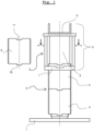
- the base section comprises a plate underneath and a threaded bolt protruding from the plate.
- the vertical assembly comprises sections 4 mounted on one another in a vertical direction.
- the sections 4 are essentially threaded sleeves with a vertically aligned axis and an external thread running along their entire length. At least the lowest of the sections 4 also has an internal thread, which is screwed to the thread of the threaded bolt of the base part 1.
- the support assembly 3 comprises a spacer part 5 and a holding part 6 rotatably arranged on its upper side, wherein the axis of rotation coincides with the axis of the threads of the sections 4.
- a part of the floor to be supported by the support which is to be held by several of the supports shown, ultimately rests on the holding part 6 from above.
- the holding part 6 is optimized so that a slat of a slat substructure of a floor surface rests on it.
- the spacer part 5 is designed in its lower area as a threaded nut 7, which is intended to be in threaded engagement with the external thread of a section 4 of the vertical assembly.
- the holding part 6 can be rotated relative to the spacer part 5.
- the spacer part 5 can be rotated around the axis of the threads of the sections 4 relative to these sections 4, whereby the height of the support can be continuously and finely adjusted.
- the spacer part 5, above its threaded nut 7 located below spans a space area 8 which is free of parts of the spacer part 5 and which is open towards the threaded nut 7 and at least in a lateral (horizontal) direction.
- the height and horizontal dimensions of this space area 8 and its openings downwards and to the side are dimensioned so large that a section 9, which is to be added as a further part to the sections 4 already forming the vertical assembly 2, can be introduced into the space area 8 through said lateral opening and can be mounted on the top side of the uppermost section 4 of the previously existing sections 4 without the spacer part having to be moved relative to the vertical assembly 2.
- This design makes it possible for the first time to change the height of a support, whose vertical assembly comprises several sections arranged one above the other, over a larger height range than the height of a section 4, without ever having to relieve the support in between. This is possible because because the section 9 that may be newly added or the section 9 that may be removed can be bridged by the spacer part 5 with regard to its supporting effect during its assembly or disassembly on the vertical assembly.
- adjacent sections 4, 9 of the vertical assembly of the support are to be connected by a plug connection between a protruding area 10 and a groove 11 that is complementary to the protruding area 10, with the plug direction being transverse to the axial direction of the sections 4, 9, i.e. horizontal when the support is upright.
- This design means that no relative movement of the two sections 4, 9 in the direction of their thread axis is required to join or separate two sections 4, 9.
- sections 4, 9 could be designed in such a way that they are joined together by a plug connection in which the plug-in direction is parallel to the thread axis.
- other types of connections such as bayonet connections, threaded connections, etc. between sections 4, 9 can also be used within the scope of the inventive concept.
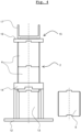
- FIG. 4 an exemplary support according to the invention is shown, in which the foot part 12 has the space area 13 required according to the invention, which in this case is open at the top to a threaded nut 14, which is in threaded engagement with a part 4 of the vertical assembly.
- the support assembly 15 is in this case formed by a disk part 16, which also serves as a handle, and a holding part 17, wherein the disk part 16 is connected to the uppermost part 4 of the vertical assembly 1 by a plug connection, and the holding part 17 on the top of the disc part 16 is rotatably mounted, wherein the axis of rotation is coaxial with the axis of the sections 4.
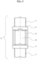
- a vertical section of another support according to the invention is outlined, in which a section 4 of the vertical assembly 18 can be removed or added at a selectable height.
- the support has a cage-like spacer 19 in which the space area 20 required according to the invention for adding or removing a section 4 of the vertical assembly 18 is located between two threaded nuts 21, which are arranged coaxially at a distance from one another and are connected by walls or rods.
- a first upper section 4 of the vertical assembly 18 is screwed into the upper threaded nut 20 and a second, lower section 4 is screwed into the lower threaded nut 20.
- the space area 20 then lies between the two aforementioned sections 4 and a third such section (not shown) of the vertical assembly 18 can be inserted into this and connected to the upper and lower sections 4.
Landscapes
- Engineering & Computer Science (AREA)
- Architecture (AREA)
- Civil Engineering (AREA)
- Structural Engineering (AREA)
- General Engineering & Computer Science (AREA)
- Floor Finish (AREA)
Applications Claiming Priority (1)
| Application Number | Priority Date | Filing Date | Title |
|---|---|---|---|
| ATA131/2022A AT525792B1 (de) | 2022-06-28 | 2022-06-28 | Stütze für das Abstützen von Fußbodenteilen |
Publications (3)
| Publication Number | Publication Date |
|---|---|
| EP4299852A1 EP4299852A1 (de) | 2024-01-03 |
| EP4299852B1 true EP4299852B1 (de) | 2025-02-19 |
| EP4299852C0 EP4299852C0 (de) | 2025-02-19 |
Family
ID=86942515
Family Applications (1)
| Application Number | Title | Priority Date | Filing Date |
|---|---|---|---|
| EP23020306.9A Active EP4299852B1 (de) | 2022-06-28 | 2023-06-21 | Stütze für das abstützen von fussbodenteilen |
Country Status (3)
| Country | Link |
|---|---|
| EP (1) | EP4299852B1 (pl) |
| AT (1) | AT525792B1 (pl) |
| PL (1) | PL4299852T3 (pl) |
Family Cites Families (6)
| Publication number | Priority date | Publication date | Assignee | Title |
|---|---|---|---|---|
| DE29707740U1 (de) * | 1997-04-29 | 1997-08-28 | Mächtle-Wöhler, Margot, 70825 Korntal-Münchingen | Hohlraumstütze mit Feuerschutzmantel |
| US6363685B1 (en) * | 2000-05-19 | 2002-04-02 | William E. Kugler | Method and apparatus for selectively adjusting the elevation of an undulating or plannar surface |
| JP4198417B2 (ja) * | 2002-08-14 | 2008-12-17 | オーエム機器株式会社 | 二重床構造及びこの二重床構造による二重床施工方法 |
| US8302356B2 (en) * | 2009-07-21 | 2012-11-06 | United Construction Products, Inc. | Support pedestal having an anchoring washer for securing elevated surface tiles |
| GB201016248D0 (en) * | 2010-09-28 | 2010-11-10 | Regent Engineering Co Walsall The Ltd | Height-adjustable floor support |
| IT201800006024A1 (it) * | 2018-06-05 | 2019-12-05 | Supporto per pavimenti sopraelevati |
-
2022
- 2022-06-28 AT ATA131/2022A patent/AT525792B1/de active
-
2023
- 2023-06-21 EP EP23020306.9A patent/EP4299852B1/de active Active
- 2023-06-21 PL PL23020306.9T patent/PL4299852T3/pl unknown
Also Published As
| Publication number | Publication date |
|---|---|
| PL4299852T3 (pl) | 2025-06-09 |
| AT525792A4 (de) | 2023-08-15 |
| EP4299852A1 (de) | 2024-01-03 |
| AT525792B1 (de) | 2023-08-15 |
| EP4299852C0 (de) | 2025-02-19 |
Similar Documents
| Publication | Publication Date | Title |
|---|---|---|
| EP2520877B1 (de) | Klemmvorrichtung für PV-Module | |
| DE2047019A1 (de) | Hebebuhne fur Kraftfahrzeuge | |
| EP3464753A1 (de) | Vertikalträgerbaugruppe für einen schwerlast-gerüstturm | |
| DE69602844T2 (de) | Gerüst und verfahren zur montage | |
| WO2008014745A1 (de) | Hubeinrichtung | |
| DE3739754C2 (pl) | ||
| EP4299852B1 (de) | Stütze für das abstützen von fussbodenteilen | |
| DE19511206C2 (de) | Hochbauentwässerungsrinne | |
| DE60000865T2 (de) | Höheneinstellbare stütze zum tragen einer tischplatte | |
| DE69006308T2 (de) | Stütz- und Verankerungsvorrichtung für vorgefertigte, insbesondere aus Beton oder ähnlichem hergestellte Gebäudeteile. | |
| DE102010032452A1 (de) | Stützeinrichtung, insbesondere zum Abstützen von Fertigböden | |
| DE3128137C2 (de) | Arbeitstisch, insbesondere Bürotisch | |
| DE69502649T2 (de) | Schalungsvorrichtung und Verfahren zur Anwendung | |
| DE3587789T2 (de) | Gewindeverstellvorrichtung. | |
| EP3247846B1 (de) | Mehrstufiges tribünensegment und montageverfahren hierfür | |
| DE202021104341U1 (de) | Nivellierbares Gargeräte-Untergestell | |
| EP1717171A2 (de) | Plattenaufteilanlage | |
| EP0235313B1 (de) | Hub- bzw. Absetzvorrichtung für transportable Grossbehälter, z. B. Kabinen, Container oder dergleichen | |
| DE29803330U1 (de) | Hubvorrichtung | |
| DE1225362B (de) | Fahrzeug-Hebebuehne mit an der Buehnenplattform angeordneten Auffahrschienen und mit einer Vorrichtung zur Entlastung der Fahrzeugfederung | |
| DE3026209C2 (de) | Spindeltreppe | |
| DE20319418U1 (de) | Fahrzeug-Hebebühne | |
| DE10260461A1 (de) | Stützfuß | |
| DE4205987A1 (de) | Vorrichtung zur schadensverhinderung an gebaeuden in bereichen von bodenbewegungen | |
| DE7535202U (de) | Buehnenpodest |
Legal Events
| Date | Code | Title | Description |
|---|---|---|---|
| PUAI | Public reference made under article 153(3) epc to a published international application that has entered the european phase |
Free format text: ORIGINAL CODE: 0009012 |
|
| STAA | Information on the status of an ep patent application or granted ep patent |
Free format text: STATUS: THE APPLICATION HAS BEEN PUBLISHED |
|
| AK | Designated contracting states |
Kind code of ref document: A1 Designated state(s): AL AT BE BG CH CY CZ DE DK EE ES FI FR GB GR HR HU IE IS IT LI LT LU LV MC ME MK MT NL NO PL PT RO RS SE SI SK SM TR |
|
| STAA | Information on the status of an ep patent application or granted ep patent |
Free format text: STATUS: REQUEST FOR EXAMINATION WAS MADE |
|
| 17P | Request for examination filed |
Effective date: 20240621 |
|
| RBV | Designated contracting states (corrected) |
Designated state(s): AL AT BE BG CH CY CZ DE DK EE ES FI FR GB GR HR HU IE IS IT LI LT LU LV MC ME MK MT NL NO PL PT RO RS SE SI SK SM TR |
|
| RIC1 | Information provided on ipc code assigned before grant |
Ipc: E04F 15/024 20060101AFI20240710BHEP |
|
| GRAP | Despatch of communication of intention to grant a patent |
Free format text: ORIGINAL CODE: EPIDOSNIGR1 |
|
| STAA | Information on the status of an ep patent application or granted ep patent |
Free format text: STATUS: GRANT OF PATENT IS INTENDED |
|
| INTG | Intention to grant announced |
Effective date: 20240923 |
|
| GRAS | Grant fee paid |
Free format text: ORIGINAL CODE: EPIDOSNIGR3 |
|
| GRAA | (expected) grant |
Free format text: ORIGINAL CODE: 0009210 |
|
| STAA | Information on the status of an ep patent application or granted ep patent |
Free format text: STATUS: THE PATENT HAS BEEN GRANTED |
|
| AK | Designated contracting states |
Kind code of ref document: B1 Designated state(s): AL AT BE BG CH CY CZ DE DK EE ES FI FR GB GR HR HU IE IS IT LI LT LU LV MC ME MK MT NL NO PL PT RO RS SE SI SK SM TR |
|
| REG | Reference to a national code |
Ref country code: GB Ref legal event code: FG4D Free format text: NOT ENGLISH |
|
| REG | Reference to a national code |
Ref country code: CH Ref legal event code: EP |
|
| REG | Reference to a national code |
Ref country code: IE Ref legal event code: FG4D Free format text: LANGUAGE OF EP DOCUMENT: GERMAN |
|
| REG | Reference to a national code |
Ref country code: DE Ref legal event code: R096 Ref document number: 502023000561 Country of ref document: DE |
|
| U01 | Request for unitary effect filed |
Effective date: 20250317 |
|
| U07 | Unitary effect registered |
Designated state(s): AT BE BG DE DK EE FI FR IT LT LU LV MT NL PT RO SE SI Effective date: 20250411 |
|
| PG25 | Lapsed in a contracting state [announced via postgrant information from national office to epo] |
Ref country code: RS Free format text: LAPSE BECAUSE OF FAILURE TO SUBMIT A TRANSLATION OF THE DESCRIPTION OR TO PAY THE FEE WITHIN THE PRESCRIBED TIME-LIMIT Effective date: 20250519 |
|
| PGFP | Annual fee paid to national office [announced via postgrant information from national office to epo] |
Ref country code: PL Payment date: 20250613 Year of fee payment: 3 |
|
| PG25 | Lapsed in a contracting state [announced via postgrant information from national office to epo] |
Ref country code: ES Free format text: LAPSE BECAUSE OF FAILURE TO SUBMIT A TRANSLATION OF THE DESCRIPTION OR TO PAY THE FEE WITHIN THE PRESCRIBED TIME-LIMIT Effective date: 20250219 |
|
| PG25 | Lapsed in a contracting state [announced via postgrant information from national office to epo] |
Ref country code: IS Free format text: LAPSE BECAUSE OF FAILURE TO SUBMIT A TRANSLATION OF THE DESCRIPTION OR TO PAY THE FEE WITHIN THE PRESCRIBED TIME-LIMIT Effective date: 20250619 Ref country code: NO Free format text: LAPSE BECAUSE OF FAILURE TO SUBMIT A TRANSLATION OF THE DESCRIPTION OR TO PAY THE FEE WITHIN THE PRESCRIBED TIME-LIMIT Effective date: 20250519 |
|
| PG25 | Lapsed in a contracting state [announced via postgrant information from national office to epo] |
Ref country code: HR Free format text: LAPSE BECAUSE OF FAILURE TO SUBMIT A TRANSLATION OF THE DESCRIPTION OR TO PAY THE FEE WITHIN THE PRESCRIBED TIME-LIMIT Effective date: 20250219 |
|
| PG25 | Lapsed in a contracting state [announced via postgrant information from national office to epo] |
Ref country code: GR Free format text: LAPSE BECAUSE OF FAILURE TO SUBMIT A TRANSLATION OF THE DESCRIPTION OR TO PAY THE FEE WITHIN THE PRESCRIBED TIME-LIMIT Effective date: 20250520 |
|
| U20 | Renewal fee for the european patent with unitary effect paid |
Year of fee payment: 3 Effective date: 20250623 |
|
| PG25 | Lapsed in a contracting state [announced via postgrant information from national office to epo] |
Ref country code: SM Free format text: LAPSE BECAUSE OF FAILURE TO SUBMIT A TRANSLATION OF THE DESCRIPTION OR TO PAY THE FEE WITHIN THE PRESCRIBED TIME-LIMIT Effective date: 20250219 |
|
| PG25 | Lapsed in a contracting state [announced via postgrant information from national office to epo] |
Ref country code: CZ Free format text: LAPSE BECAUSE OF FAILURE TO SUBMIT A TRANSLATION OF THE DESCRIPTION OR TO PAY THE FEE WITHIN THE PRESCRIBED TIME-LIMIT Effective date: 20250219 |
|
| PG25 | Lapsed in a contracting state [announced via postgrant information from national office to epo] |
Ref country code: SK Free format text: LAPSE BECAUSE OF FAILURE TO SUBMIT A TRANSLATION OF THE DESCRIPTION OR TO PAY THE FEE WITHIN THE PRESCRIBED TIME-LIMIT Effective date: 20250219 |
|
| PLBE | No opposition filed within time limit |
Free format text: ORIGINAL CODE: 0009261 |
|
| STAA | Information on the status of an ep patent application or granted ep patent |
Free format text: STATUS: NO OPPOSITION FILED WITHIN TIME LIMIT |
|
| 26N | No opposition filed |
Effective date: 20251120 |
|
| PG25 | Lapsed in a contracting state [announced via postgrant information from national office to epo] |
Ref country code: MC Free format text: LAPSE BECAUSE OF FAILURE TO SUBMIT A TRANSLATION OF THE DESCRIPTION OR TO PAY THE FEE WITHIN THE PRESCRIBED TIME-LIMIT Effective date: 20250219 |