EP4299274A1 - Injection-molded body and production method therefor - Google Patents
Injection-molded body and production method therefor Download PDFInfo
- Publication number
- EP4299274A1 EP4299274A1 EP22759284.7A EP22759284A EP4299274A1 EP 4299274 A1 EP4299274 A1 EP 4299274A1 EP 22759284 A EP22759284 A EP 22759284A EP 4299274 A1 EP4299274 A1 EP 4299274A1
- Authority
- EP
- European Patent Office
- Prior art keywords
- injection molded
- molded article
- copolymer
- mold
- gate
- Prior art date
- Legal status (The legal status is an assumption and is not a legal conclusion. Google has not performed a legal analysis and makes no representation as to the accuracy of the status listed.)
- Granted
Links
Images

Classifications
-
- C—CHEMISTRY; METALLURGY
- C08—ORGANIC MACROMOLECULAR COMPOUNDS; THEIR PREPARATION OR CHEMICAL WORKING-UP; COMPOSITIONS BASED THEREON
- C08F—MACROMOLECULAR COMPOUNDS OBTAINED BY REACTIONS ONLY INVOLVING CARBON-TO-CARBON UNSATURATED BONDS
- C08F214/00—Copolymers of compounds having one or more unsaturated aliphatic radicals, each having only one carbon-to-carbon double bond, and at least one being terminated by a halogen
- C08F214/18—Monomers containing fluorine
- C08F214/26—Tetrafluoroethene
- C08F214/262—Tetrafluoroethene with fluorinated vinyl ethers
-
- B—PERFORMING OPERATIONS; TRANSPORTING
- B29—WORKING OF PLASTICS; WORKING OF SUBSTANCES IN A PLASTIC STATE IN GENERAL
- B29C—SHAPING OR JOINING OF PLASTICS; SHAPING OF MATERIAL IN A PLASTIC STATE, NOT OTHERWISE PROVIDED FOR; AFTER-TREATMENT OF THE SHAPED PRODUCTS, e.g. REPAIRING
- B29C45/00—Injection moulding, i.e. forcing the required volume of moulding material through a nozzle into a closed mould; Apparatus therefor
- B29C45/0001—Injection moulding, i.e. forcing the required volume of moulding material through a nozzle into a closed mould; Apparatus therefor characterised by the choice of material
-
- B—PERFORMING OPERATIONS; TRANSPORTING
- B29—WORKING OF PLASTICS; WORKING OF SUBSTANCES IN A PLASTIC STATE IN GENERAL
- B29C—SHAPING OR JOINING OF PLASTICS; SHAPING OF MATERIAL IN A PLASTIC STATE, NOT OTHERWISE PROVIDED FOR; AFTER-TREATMENT OF THE SHAPED PRODUCTS, e.g. REPAIRING
- B29C45/00—Injection moulding, i.e. forcing the required volume of moulding material through a nozzle into a closed mould; Apparatus therefor
- B29C45/0046—Details relating to the filling pattern or flow paths or flow characteristics of moulding material in the mould cavity
-
- B—PERFORMING OPERATIONS; TRANSPORTING
- B29—WORKING OF PLASTICS; WORKING OF SUBSTANCES IN A PLASTIC STATE IN GENERAL
- B29C—SHAPING OR JOINING OF PLASTICS; SHAPING OF MATERIAL IN A PLASTIC STATE, NOT OTHERWISE PROVIDED FOR; AFTER-TREATMENT OF THE SHAPED PRODUCTS, e.g. REPAIRING
- B29C45/00—Injection moulding, i.e. forcing the required volume of moulding material through a nozzle into a closed mould; Apparatus therefor
- B29C45/17—Component parts, details or accessories; Auxiliary operations
- B29C45/26—Moulds
-
- B—PERFORMING OPERATIONS; TRANSPORTING
- B29—WORKING OF PLASTICS; WORKING OF SUBSTANCES IN A PLASTIC STATE IN GENERAL
- B29C—SHAPING OR JOINING OF PLASTICS; SHAPING OF MATERIAL IN A PLASTIC STATE, NOT OTHERWISE PROVIDED FOR; AFTER-TREATMENT OF THE SHAPED PRODUCTS, e.g. REPAIRING
- B29C45/00—Injection moulding, i.e. forcing the required volume of moulding material through a nozzle into a closed mould; Apparatus therefor
- B29C45/17—Component parts, details or accessories; Auxiliary operations
- B29C45/26—Moulds
- B29C45/27—Sprue channels ; Runner channels or runner nozzles
- B29C45/2701—Details not specific to hot or cold runner channels
- B29C45/2708—Gates
-
- B—PERFORMING OPERATIONS; TRANSPORTING
- B29—WORKING OF PLASTICS; WORKING OF SUBSTANCES IN A PLASTIC STATE IN GENERAL
- B29C—SHAPING OR JOINING OF PLASTICS; SHAPING OF MATERIAL IN A PLASTIC STATE, NOT OTHERWISE PROVIDED FOR; AFTER-TREATMENT OF THE SHAPED PRODUCTS, e.g. REPAIRING
- B29C45/00—Injection moulding, i.e. forcing the required volume of moulding material through a nozzle into a closed mould; Apparatus therefor
- B29C45/17—Component parts, details or accessories; Auxiliary operations
- B29C45/76—Measuring, controlling or regulating
- B29C45/78—Measuring, controlling or regulating of temperature
-
- C—CHEMISTRY; METALLURGY
- C08—ORGANIC MACROMOLECULAR COMPOUNDS; THEIR PREPARATION OR CHEMICAL WORKING-UP; COMPOSITIONS BASED THEREON
- C08F—MACROMOLECULAR COMPOUNDS OBTAINED BY REACTIONS ONLY INVOLVING CARBON-TO-CARBON UNSATURATED BONDS
- C08F214/00—Copolymers of compounds having one or more unsaturated aliphatic radicals, each having only one carbon-to-carbon double bond, and at least one being terminated by a halogen
- C08F214/18—Monomers containing fluorine
-
- C—CHEMISTRY; METALLURGY
- C08—ORGANIC MACROMOLECULAR COMPOUNDS; THEIR PREPARATION OR CHEMICAL WORKING-UP; COMPOSITIONS BASED THEREON
- C08F—MACROMOLECULAR COMPOUNDS OBTAINED BY REACTIONS ONLY INVOLVING CARBON-TO-CARBON UNSATURATED BONDS
- C08F214/00—Copolymers of compounds having one or more unsaturated aliphatic radicals, each having only one carbon-to-carbon double bond, and at least one being terminated by a halogen
- C08F214/18—Monomers containing fluorine
- C08F214/26—Tetrafluoroethene
-
- C—CHEMISTRY; METALLURGY
- C08—ORGANIC MACROMOLECULAR COMPOUNDS; THEIR PREPARATION OR CHEMICAL WORKING-UP; COMPOSITIONS BASED THEREON
- C08F—MACROMOLECULAR COMPOUNDS OBTAINED BY REACTIONS ONLY INVOLVING CARBON-TO-CARBON UNSATURATED BONDS
- C08F216/00—Copolymers of compounds having one or more unsaturated aliphatic radicals, each having only one carbon-to-carbon double bond, and at least one being terminated by an alcohol, ether, aldehydo, ketonic, acetal or ketal radical
- C08F216/12—Copolymers of compounds having one or more unsaturated aliphatic radicals, each having only one carbon-to-carbon double bond, and at least one being terminated by an alcohol, ether, aldehydo, ketonic, acetal or ketal radical by an ether radical
- C08F216/14—Monomers containing only one unsaturated aliphatic radical
- C08F216/1408—Monomers containing halogen
-
- C—CHEMISTRY; METALLURGY
- C08—ORGANIC MACROMOLECULAR COMPOUNDS; THEIR PREPARATION OR CHEMICAL WORKING-UP; COMPOSITIONS BASED THEREON
- C08F—MACROMOLECULAR COMPOUNDS OBTAINED BY REACTIONS ONLY INVOLVING CARBON-TO-CARBON UNSATURATED BONDS
- C08F8/00—Chemical modification by after-treatment
- C08F8/18—Introducing halogen atoms or halogen-containing groups
- C08F8/20—Halogenation
- C08F8/22—Halogenation by reaction with free halogens
-
- C—CHEMISTRY; METALLURGY
- C08—ORGANIC MACROMOLECULAR COMPOUNDS; THEIR PREPARATION OR CHEMICAL WORKING-UP; COMPOSITIONS BASED THEREON
- C08J—WORKING-UP; GENERAL PROCESSES OF COMPOUNDING; AFTER-TREATMENT NOT COVERED BY SUBCLASSES C08B, C08C, C08F, C08G or C08H
- C08J5/00—Manufacture of articles or shaped materials containing macromolecular substances
- C08J5/18—Manufacture of films or sheets
-
- B—PERFORMING OPERATIONS; TRANSPORTING
- B29—WORKING OF PLASTICS; WORKING OF SUBSTANCES IN A PLASTIC STATE IN GENERAL
- B29C—SHAPING OR JOINING OF PLASTICS; SHAPING OF MATERIAL IN A PLASTIC STATE, NOT OTHERWISE PROVIDED FOR; AFTER-TREATMENT OF THE SHAPED PRODUCTS, e.g. REPAIRING
- B29C45/00—Injection moulding, i.e. forcing the required volume of moulding material through a nozzle into a closed mould; Apparatus therefor
- B29C45/17—Component parts, details or accessories; Auxiliary operations
- B29C45/72—Heating or cooling
- B29C45/73—Heating or cooling of the mould
-
- B—PERFORMING OPERATIONS; TRANSPORTING
- B29—WORKING OF PLASTICS; WORKING OF SUBSTANCES IN A PLASTIC STATE IN GENERAL
- B29C—SHAPING OR JOINING OF PLASTICS; SHAPING OF MATERIAL IN A PLASTIC STATE, NOT OTHERWISE PROVIDED FOR; AFTER-TREATMENT OF THE SHAPED PRODUCTS, e.g. REPAIRING
- B29C45/00—Injection moulding, i.e. forcing the required volume of moulding material through a nozzle into a closed mould; Apparatus therefor
- B29C45/17—Component parts, details or accessories; Auxiliary operations
- B29C45/72—Heating or cooling
- B29C45/74—Heating or cooling of the injection unit
-
- B—PERFORMING OPERATIONS; TRANSPORTING
- B29—WORKING OF PLASTICS; WORKING OF SUBSTANCES IN A PLASTIC STATE IN GENERAL
- B29K—INDEXING SCHEME ASSOCIATED WITH SUBCLASSES B29B, B29C OR B29D, RELATING TO MOULDING MATERIALS OR TO MATERIALS FOR MOULDS, REINFORCEMENTS, FILLERS OR PREFORMED PARTS, e.g. INSERTS
- B29K2027/00—Use of polyvinylhalogenides or derivatives thereof as moulding material
- B29K2027/12—Use of polyvinylhalogenides or derivatives thereof as moulding material containing fluorine
-
- B—PERFORMING OPERATIONS; TRANSPORTING
- B29—WORKING OF PLASTICS; WORKING OF SUBSTANCES IN A PLASTIC STATE IN GENERAL
- B29K—INDEXING SCHEME ASSOCIATED WITH SUBCLASSES B29B, B29C OR B29D, RELATING TO MOULDING MATERIALS OR TO MATERIALS FOR MOULDS, REINFORCEMENTS, FILLERS OR PREFORMED PARTS, e.g. INSERTS
- B29K2027/00—Use of polyvinylhalogenides or derivatives thereof as moulding material
- B29K2027/12—Use of polyvinylhalogenides or derivatives thereof as moulding material containing fluorine
- B29K2027/18—PTFE, i.e. polytetrafluoroethylene, e.g. ePTFE, i.e. expanded polytetrafluoroethylene
-
- C—CHEMISTRY; METALLURGY
- C08—ORGANIC MACROMOLECULAR COMPOUNDS; THEIR PREPARATION OR CHEMICAL WORKING-UP; COMPOSITIONS BASED THEREON
- C08F—MACROMOLECULAR COMPOUNDS OBTAINED BY REACTIONS ONLY INVOLVING CARBON-TO-CARBON UNSATURATED BONDS
- C08F8/00—Chemical modification by after-treatment
-
- C—CHEMISTRY; METALLURGY
- C08—ORGANIC MACROMOLECULAR COMPOUNDS; THEIR PREPARATION OR CHEMICAL WORKING-UP; COMPOSITIONS BASED THEREON
- C08J—WORKING-UP; GENERAL PROCESSES OF COMPOUNDING; AFTER-TREATMENT NOT COVERED BY SUBCLASSES C08B, C08C, C08F, C08G or C08H
- C08J2327/00—Characterised by the use of homopolymers or copolymers of compounds having one or more unsaturated aliphatic radicals, each having only one carbon-to-carbon double bond, and at least one being terminated by a halogen; Derivatives of such polymers
- C08J2327/02—Characterised by the use of homopolymers or copolymers of compounds having one or more unsaturated aliphatic radicals, each having only one carbon-to-carbon double bond, and at least one being terminated by a halogen; Derivatives of such polymers not modified by chemical after-treatment
- C08J2327/12—Characterised by the use of homopolymers or copolymers of compounds having one or more unsaturated aliphatic radicals, each having only one carbon-to-carbon double bond, and at least one being terminated by a halogen; Derivatives of such polymers not modified by chemical after-treatment containing fluorine atoms
- C08J2327/18—Homopolymers or copolymers of tetrafluoroethylene
Definitions
- the present disclosure relates to an injection molded article and a method for producing the same.
- Patent Document 1 describes an ozone-resistant injection molded article comprising a perfluororesin, wherein the perfluororesin is composed of a perfluoro polymer, has an MIT value of 300,000 cycles or more, and has not more than 50 unstable end groups per 1 ⁇ 10 6 carbon atoms in the perfluoro polymer.
- Patent Document 1 International Publication No. WO 2003/048214
- An object of the present disclosure is to provide an injection molded article which is excellent in the abrasion resistance at 90°C, the long-time tensile creep property, the chemical solution low permeability, the rigidity on heating and the heat distortion resistance after chemical immersion, hardly makes fluorine ions dissolve out in a chemical solution, and has a beautiful appearance and a high flow length.
- an injection molded article obtained by injection molding a copolymer using a mold provided with a gate, wherein the copolymer contains tetrafluoroethylene (TFE) unit and a fluoro(alkyl vinyl ether) (FAVE) unit, the content of the fluoro(alkyl vinyl ether) unit of the copolymer is 3.5 to 4.7% by mass with respect to the whole of the monomer units, the melt flow rate at 372°C of the copolymer is 22.0 to 35.0 g/10 min, the number of functional groups of the copolymer is 20 or less per 10 6 main-chain carbon atoms, and the injection molded article has a gate section corresponding to the gate of the mold, and the ratio of a maximum flow length (a) from the gate section of the injection molded article to an average value (b) of a product thickness on the maximum flow length, ((a)/(b)), is 80 to 200.
- TFE tetrafluoroethylene
- FAVE fluoro(al
- the fluoro(alkyl vinyl ether) unit of the copolymer is preferably perfluoro(propyl vinyl ether) unit.
- the content of the fluoro(alkyl vinyl ether) unit of the copolymer is preferably 3.9 to 4.5% by mass with respect to the whole of the monomer units.
- the melt flow rate at 372°C of the copolymer is preferably 24.2 to 30.0 g/10 min.
- the melting point of the copolymer is preferably 295 to 305°C.
- the injection molded article of the present disclosure further has a weld section, and the ratio of a maximum depth (D) of the weld section to a maximum thickness (L) of the injection molded article, (D/L), is 0.8 or less.
- a method for producing the above injection molded article comprising: injection molding the copolymer by using an injection molding machine and the mold provided with the gate, wherein the ratio of a maximum flow length (c) from the gate section of the mold to an average value (d) of a cavity thickness of the mold on the maximum flow length, ((c)/(d)), is 80 to 200.
- the temperature of the mold is preferably 150 to 250°C.
- the cylinder temperature of the injection molding machine is preferably 350 to 420°C.
- an injection molded article which is excellent in the abrasion resistance at 90°C, the long-time tensile creep property, the chemical solution low permeability, the rigidity on heating and the heat distortion resistance after chemical immersion, hardly makes fluorine ions dissolve out in a chemical solution, and has a beautiful appearance and a high flow length.
- Patent Document 1 proposes, in particular, as an article excellent in the ozone resistance such as a piping member or a joint used in a semiconductor production apparatus, an ozone-resistant injection molded article comprising a perfluororesin, wherein the perfluororesin is composed of a perfluoro polymer, has an MIT value of 300,000 cycles or more, and has not more than 50 unstable end groups per 1 ⁇ 10 6 carbon atoms in the perfluoro polymer. It is also described in Examples of Patent Document 1 that a cap nut of 43 mm in minimum outer diameter, 27.02 mm in internal diameter, and 30 mm in height is produced by injection molding using an injection molding machine.
- Patent Document 1 it is difficult to use the ozone-resistant injection molded article described in Patent Document 1 as an injection molded article having a beautiful appearance and a high flow length.
- piping members that are used to transfer a chemical solution, such as joints, and flowmeter members for measuring the flow rate of a chemical solution often have a complicated shape, and they are required to have a beautiful appearance.
- a chemical solution at a high pressure or a chemical solution at a high temperature is allowed to flow, the chemical solution at a high pressure or the chemical solution at a high temperature passes through the piping member or the flowmeter member.
- the pressure of the chemical solution frequently varies, for example, at the start of the supply of fluid, at the stop of the supply of fluid, at the change of the supply pressure of fluid, not only the durability against a chemical solution at a high pressure and a high temperature, but also the durability against the variation of pressure is also required. Therefore, there is required an injection molded article which is excellent in the abrasion resistance at high temperatures, the long-time tensile creep property, the chemical solution low permeability, the rigidity on heating and the heat distortion resistance after chemical immersion, and has a beautiful appearance and a high flow length.
- the injection molded article of the present disclosure is an injection molded article obtained by injection molding a specific copolymer using a mold provided with a gate, the injection molded article has a gate section corresponding to the gate of the mold, and the ratio of the maximum flow length (a) from the gate section of the injection molded article to the average value (b) of the product thickness on the maximum flow length, ((a)/(b)), is 80 to 200.
- the injection molded article of the present disclosure due to having such a configuration, is excellent in the abrasion resistance at 90°C, the long-time tensile creep property, the chemical solution low permeability, the rigidity on heating and the heat distortion resistance after chemical immersion, hardly makes fluorine ions dissolve out in a chemical solution, and has a beautiful appearance and a high flow length.
- the injection molded article of the present disclosure has a gate section.
- the gate section corresponds to the gate provided in the mold used in injection molding, and is usually observed on the surface of an injection molded article as a gate mark that remains on the injection molded article after the gate and the injection molded article are separated from each other.
- the number of the gate section is not limited, and is preferably 1 or more, may be 4 or less, and is more preferably 1.
- the injection molded article of the present disclosure has a high flow length, and the ratio of the maximum flow length (a) from the gate section of the injection molded article to the average value (b) of the product thickness on the maximum flow length, ((a)/(b)), is 80 to 200.
- the ratio ((a)/(b)) is preferably 85 or more, more preferably 87 or more, still more preferably 90 or more, especially preferably 94 or more, and most preferably 100 or more, and preferably 150 or less, and more preferably 135 or less.
- forming defects such as scratches and surface delamination are likely to remain, and the smoothness is likely to deteriorate.
- injection molded articles having a low flow length As injection molded articles that are likely to have a long flow length, such as piping members that are used to transfer a chemical solution, such as joints, and flowmeter members for measuring the flow rate of a chemical solution, even when the conventional injection molded articles are excellent in the rigidity on heating and the heat distortion resistance after chemical immersion.
- the injection molded article of the present disclosure is excellent in the abrasion resistance at 90°C, the long-time tensile creep property, the chemical solution low permeability, the rigidity on heating and the heat distortion resistance after chemical immersion, and furthermore, has a high flow length.
- the maximum flow length (a) from the gate section refers to the distance the copolymer has flowed in a mold, and can be specified by, for example, measuring the distance between the gate section and the weld section generated at the portion where the copolymer flowed in the mold joins.
- the maximum flow length from the gate section (a) can be specified by measuring the distance between the gate section and the edge of the injection molded article which is located farthest from the gate section.
- the copolymer has flowed in a mold can be specified, for example, when an injection molded article has a plurality of gate sections, the longest distance among the specified distances is determined as the maximum flow length (a) from the gate section.
- the ratio ((a)/(b)) can be determined by dividing the maximum flow length (a) determined as above by the average value (b) of the product thickness on the maximum flow length.
- the average value (b) of the product thickness on the maximum flow length can be calculated by measuring the minimum diameter of a cross section orthogonal to a line drawn to measure the maximum flow length (a) (the product thickness on the maximum flow length, when the cross section is a quadrangle, the short side) for every 2 mm along the line drawn to measure the maximum flow length, integrating the measured values, and calculating the average of the measured values.
- the injection molded article of the present disclosure usually has a weld section corresponding to a portion where a resin has flowed in a mold and joined.
- the weld section can usually be observed as a weld line on the surface of the injection molded article.
- a hardly visible weld line is also included in the weld section.
- the injection molded article of the present disclosure has a beautiful appearance and has a small maximum depth of the weld section.
- the ratio of the maximum depth (D) of the weld section to the maximum thickness (L) of the injection molded article, (D/L) is preferably 0.8 or lower, more preferably 0.7 or lower, still more preferably 0.5 or lower, further still more preferably 0.3 or lower, and especially preferably 0.2 or lower. It can be said that as the maximum depth of the weld section is smaller, the surface of the injection molded article is smoother, and the injection molded article is more excellent in the transparency. It has also been found that as the ratio of the maximum depth (D) of the weld section to the maximum thickness (L) of the injection molded article, (D/L), is smaller, the tensile strength of the injection molded article increases significantly.
- the injection molded article of the present disclosure contains a copolymer containing tetrafluoroethylene (TFE) unit and a fluoro(alkyl vinyl ether) (FAVE) unit.
- the copolymer is a melt-fabricable fluororesin. Being melt-fabricable means that a polymer can be melted and processed by using a conventional processing device such as an extruder or an injection molding machine.
- the above FAVE is preferably the monomer represented by the general formula (1), more preferably at least one selected from the group consisting of perfluoro(methyl vinyl ether), perfluoro(ethyl vinyl ether) (PEVE) and perfluoro(propyl vinyl ether) (PPVE), still more preferably at least one selected from the group consisting of PEVE and PPVE, and particularly preferably PPVE.
- the content of the FAVE unit of the copolymer is 3.5 to 4.7% by mass with respect to the whole of the monomer units.
- the content of the FAVE unit of the copolymer is preferably 3.6% by mass or higher, more preferably 3.7% by mass or higher, still more preferably 3.8% by mass or higher, and especially preferably 3.9% by mass or higher, and preferably 4.6% by mass or lower, and more preferably 4.5% by mass or lower.
- the content of the FAVE unit of the copolymer is too high, the rigidity on heating, the long-time tensile creep property and the chemical solution low permeability of the injection molded article deteriorate.
- the content of the FAVE unit of the copolymer is too low, the abrasion resistance at 90°C and the heat distortion resistance after chemical immersion of the injection molded article deteriorate.
- the content of the TFE unit of the copolymer is, with respect to the whole of the monomer units, preferably 95.3 to 96.5% by mass, more preferably 95.4% by mass or higher, and still more preferably 95.5% by mass or higher, and more preferably 96.4% by mass or lower, still more preferably 96.3% by mass or lower, further still more preferably 96.2% by mass or lower, and especially preferably 96.1% by mass or lower.
- the content of the TFE unit of the copolymer is too low, the rigidity on heating, the long-time tensile creep property and the chemical solution low permeability of the injection molded article may deteriorate.
- the content of the TFE unit of the copolymer is too high, the abrasion resistance at 90°C and the heat distortion resistance after chemical immersion of the injection molded article may deteriorate.
- the content of each monomer unit in the copolymer is measured by a 19 F-NMR method.
- the copolymer can also contain a monomer unit originated from a monomer copolymerizable with TFE and FAVE.
- the content of the monomer unit copolymerizable with TFE and FAVE is, with respect to the whole of the monomer units of the copolymer, preferably 0 to 1.2% by mass, more preferably 0.05 to 0.5% by mass, and still more preferably 0.1 to 0.3% by mass.
- HFP hexafluoropropylene
- the copolymer is preferably at least one selected from the group consisting of a copolymer consisting only of the TFE unit and the FAVE unit, and TFE/HFP/FAVE copolymer, and is more preferably a copolymer consisting only of the TFE unit and the FAVE unit.
- the melt flow rate (MFR) of the copolymer is 22.0 to 35.0 g/10 min.
- the MFR of the copolymer is preferably 23.0 g/10 min or higher, and more preferably 24.0 g/10 min or higher, and preferably 33.0 g/10 min or lower, more preferably 32.0 g/10 min or lower, still more preferably 31.0 g/10 min or lower, and especially preferably 30.0 g/10 min or lower.
- MFR of the copolymer is too low, not only the chemical solution low permeability and the appearance of the injection molded article deteriorate, but also an injection molded article having a flow length may not be obtained.
- the MFR of the copolymer is too high, the abrasion resistance at 90°C and the heat distortion resistance after chemical immersion of the injection molded article deteriorate.
- the MFR is a value obtained as a mass (g/10 min) of the polymer flowing out from a nozzle of 2.1 mm in inner diameter and 8 mm in length per 10 min at 372°C under a load of 5 kg using a melt indexer, according to ASTM D1238.
- the MFR can be regulated by regulating the kind and amount of a polymerization initiator to be used in polymerization of monomers, the kind and amount of a chain transfer agent, and the like.
- the number of functional groups per 10 6 main-chain carbon atoms of the copolymer is 20 or less, preferably 15 or less, more preferably 10 or less, and still more preferably less than 6. Due to that the number of functional groups of the copolymer is within the above range, the chemical solution low permeability of the injection molded article can be improved, and the amount of fluorine ions dissolving out from the injection molded article in a chemical solution can be significantly reduced.
- infrared spectroscopy For identification of the kind of the functional groups and measurement of the number of the functional groups, infrared spectroscopy can be used.
- the number of the functional groups is measured, specifically, by the following method.
- the copolymer is formed by cold press to prepare a film of 0.25 to 0.30 mm in thickness.
- the film is analyzed by Fourier transform infrared spectroscopy to obtain an infrared absorption spectrum of the copolymer, and a difference spectrum against a base spectrum that is completely fluorinated and has no functional groups is obtained. From an absorption peak of a specific functional group observed on this difference spectrum, the number N of the functional group per 1 ⁇ 10 6 carbon atoms in the copolymer is calculated according to the following formula (A).
- N I ⁇ K / t
- the absorption frequency, the molar absorption coefficient and the correction factor are shown in Table 1. Then, the molar absorption coefficients are those determined from FT-IR measurement data of low molecular model compounds.
- Absorption frequencies of -CH 2 CF 2 H, -CH 2 COF, -CH 2 COOH, -CH 2 COOCH 3 and -CH 2 CONH 2 are lower by a few tens of kaysers (cm -1 ) than those of -CF 2 H, -COF, -COOH free and -COOH bonded, -COOCH 3 and -CONH 2 shown in the Table, respectively.
- the number of the functional group -COF is the total of the number of a functional group determined from an absorption peak having an absorption frequency of 1,883 cm -1 derived from -CF 2 COF and the number of a functional group determined from an absorption peak having an absorption frequency of 1,840 cm -1 derived from -CH 2 COF.
- the functional groups are ones present on main chain terminals or side chain terminals of the copolymer, and ones present in the main chain or the side chains.
- the functional groups are introduced to the copolymer by, for example, a chain transfer agent or a polymerization initiator used for production of the copolymer.
- a chain transfer agent for example, a chain transfer agent, or a polymerization initiator used for production of the copolymer.
- -CH 2 OH is introduced on the main chain terminals of the copolymer.
- the functional group is introduced on the side chain terminal of the copolymer by polymerizing a monomer having the functional group.
- the copolymer satisfying the above range regarding the number of functional groups can be obtained by subjecting the copolymer to a fluorination treatment. That is, the copolymer contained in the injection molded article of the present disclosure is preferably one which is subjected to the fluorination treatment. Further, the copolymer contained in the injection molded article of the present disclosure preferably has -CF 3 terminal groups.
- the melting point of the copolymer is preferably 295 to 315°C, more preferably 300°C or higher, still more preferably 301°C or higher, and especially preferably 302°C or higher, and more preferably 310°C or lower, and still more preferably 305°C or lower. Due to that the melting point is in the above range, the abrasion resistance at 90°C, the long-time tensile creep property, the chemical solution low permeability, the rigidity on heating and the heat distortion resistance after chemical immersion are further improved, even when the flow length of the injection molded article is high.
- the melting point can be measured by using a differential scanning calorimeter [DSC].
- the methyl ethyl ketone (MEK) permeability of the injection molded article of the present disclosure is preferably 74.0 g/m 2 or lower.
- MEK methyl ethyl ketone
- the MEK permeability can be measured under the condition of a temperature of 60°C and for 60 days. Specific measurement of the MEK permeability can be carried out by a method described in Examples.
- the amount of fluorine ions dissolving out therefrom detected by a hydrogen peroxide solution immersion test is, in terms of mass, preferably 5.0 ppm or lower, more preferably 4.0 ppm or lower and still more preferably 3.0 ppm or lower.
- the injection molded article of the present disclosure is used as, for example, piping members that are used to transfer a chemical solution, such as joints, and flowmeter members for measuring the flow rate of a chemical solution, the contamination of the chemical solution by fluorine ions can be highly suppressed.
- the hydrogen peroxide solution immersion test can be carried out by preparing a test piece having a weight corresponding to that of 30 formed articles (40 mm ⁇ 40 mm ⁇ 0.5 mmt), immersing the test piece in 50 g of a 3% by weight aqueous hydrogen peroxide solution, heating the test piece at 90°C for 20 hours, and further heating the test piece at 121°C for 3 hours.
- the injection molded article of the present disclosure may contain other components such as fillers, plasticizers, processing aids, mold release agents, pigments, flame retarders, lubricants, light stabilizers, weathering stabilizers, electrically conductive agents, antistatic agents, ultraviolet absorbents, antioxidants, foaming agents, perfumes, oils, softening agents and dehydrofluorination agents.
- other components such as fillers, plasticizers, processing aids, mold release agents, pigments, flame retarders, lubricants, light stabilizers, weathering stabilizers, electrically conductive agents, antistatic agents, ultraviolet absorbents, antioxidants, foaming agents, perfumes, oils, softening agents and dehydrofluorination agents.
- the fillers include silica, kaolin, clay, organo clay, talc, mica, alumina, calcium carbonate, calcium terephthalate, titanium oxide, calcium phosphate, calcium fluoride, lithium fluoride, crosslinked polystyrene, potassium titanate, carbon, boron nitride, carbon nanotube and glass fiber.
- the electrically conductive agents include carbon black.
- the plasticizers include dioctyl phthalate and pentaerythritol.
- the processing aids include carnauba wax, sulfone compounds, low molecular weight polyethylene and fluorine-based auxiliary agents.
- the dehydrofluorination agents include organic oniums and amidines.
- other polymers other than the copolymer may be used.
- the other polymers include fluororesins other than the copolymer, fluoroelastomer, and non-fluorinated polymers.
- the copolymer contained in the injection molded article of the present disclosure can be produced by a polymerization method such as suspension polymerization, solution polymerization, emulsion polymerization or bulk polymerization.
- the polymerization method is preferably emulsion polymerization or suspension polymerization.
- conditions such as temperature and pressure, and a polymerization initiator and other additives can suitably be set depending on the formulation and the amount of the copolymer.
- an oil-soluble radical polymerization initiator or a water-soluble radical polymerization initiator may be used.
- the oil-soluble radical polymerization initiator may be a known oil-soluble peroxide, and examples thereof typically include:
- the di[fluoro(or fluorochloro)acyl] peroxides include diacyl peroxides represented by [(RfCOO)-] 2 wherein Rf is a perfluoroalkyl group, an ⁇ -hydroperfluoroalkyl group or a fluorochloroalkyl group.
- di[fluoro(or fluorochloro)acyl] peroxides examples include di( ⁇ -hydro-dodecafluorohexanoyl) peroxide, di( ⁇ -hydro-tetradecafluoroheptanoyl) peroxide, di( ⁇ -hydro-hexadecafluorononanoyl) peroxide, di(perfluoropropionyl) peroxide, di(perfluorobutyryl) peroxide, di(perfluorovaleryl) peroxide, di(perfluorohexanoyl) peroxide, di(perfluoroheptanoyl) peroxide, di(perfluorooctanoyl) peroxide, di(perfluorononanoyl) peroxide, di( ⁇ -chloro-hexafluorobutyryl) peroxide, di( ⁇ -chloro-decafluorohexanoyl) peroxide,
- the water-soluble radical polymerization initiator may be a known water-soluble peroxide, and examples thereof include ammonium salts, potassium salts and sodium salts of persulfuric acid, perboric acid, perchloric acid, perphosphoric acid, percarbonic acid and the like, organic peroxides such as disuccinoyl peroxide and diglutaroyl peroxide, and t-butyl permaleate and t-butyl hydroperoxide.
- a reductant such as a sulfite salt may be combined with a peroxide and used, and the amount thereof to be used may be 0.1 to 20 times with respect to the peroxide.
- a surfactant In the polymerization, a surfactant, a chain transfer agent and a solvent may be used, which are conventionally known.
- the surfactant may be a known surfactant, for example, nonionic surfactants, anionic surfactants and cationic surfactants may be used.
- fluorine-containing anionic surfactants are preferred, and more preferred are linear or branched fluorine-containing anionic surfactants having 4 to 20 carbon atoms, which may contain an ether bond oxygen (that is, an oxygen atom may be inserted between carbon atoms).
- the amount of the surfactant to be added is preferably 50 to 5,000 ppm.
- chain transfer agent examples include hydrocarbons such as ethane, isopentane, n-hexane and cyclohexane; aromatics such as toluene and xylene; ketones such as acetone; acetate esters such as ethyl acetate and butyl acetate; alcohols such as methanol and ethanol; mercaptans such as methylmercaptan; and halogenated hydrocarbons such as carbon tetrachloride, chloroform, methylene chloride and methyl chloride.
- the amount of the chain transfer agent to be added may vary depending on the chain transfer constant value of the compound to be used, but is usually in the range of 0.01 to 20% by mass with respect to the solvent in the polymerization.
- the solvent may include water and mixed solvents of water and an alcohol.
- a fluorosolvent may be used.
- the fluorosolvent may include hydrochlorofluoroalkanes such as CH 3 CClF 2 , CH 3 CCl 2 F, CF 3 CF 2 CCl 2 H and CF 2 ClCF 2 CFHCl; chlorofluoroalaknes such as CF 2 ClCFClCF 2 CF 3 and CF 3 CFClCFClCF 3 ; hydrofluroalkanes such as CF 3 CFHCFHCF 2 CF 2 CF 3 , CF 2 HCF 2 CF 2 CF 2 CF 2 H and CF 3 CF 2 CF 2 CF 2 CF 2 CF 2 CF 2 H; hydrofluoroethers such as CH 3 OC 2 F 5 , CH 3 OC 3 F 5 CF 3 CF 2 CH 2 OCHF 2 , CF 3 CHFCF 2 OCH 3 , CHF 2 CF 2 OCH 2 F, (CF 3 ) 2
- the polymerization temperature is not limited, and may be 0 to 100°C.
- the polymerization pressure is suitably set depending on other polymerization conditions to be used such as the kind, the amount and the vapor pressure of the solvent, and the polymerization temperature, but may usually be 0 to 9.8 MPaG.
- the copolymer in the case of obtaining an aqueous dispersion containing the copolymer by the polymerization reaction, the copolymer can be recovered by coagulating, cleaning and drying the copolymer contained in the aqueous dispersion. Then in the case of obtaining the copolymer as a slurry by the polymerization reaction, the copolymer can be recovered by taking out the slurry from a reaction container, and cleaning and drying the slurry. The copolymer can be recovered in a shape of powder by the drying.
- the copolymer obtained by the polymerization may be formed into pellets.
- a method of forming into pellets is not limited, and a conventionally known method can be used. Examples thereof include methods of melt extruding the copolymer by using a single-screw extruder, a twin-screw extruder or a tandem extruder and cutting the resultant into a predetermined length to form the copolymer into pellets.
- the extrusion temperature in the melt extrusion needs to be varied depending on the melt viscosity and the production method of the copolymer, and is preferably the melting point of the copolymer + 20°C to the melting point of the copolymer + 140°C.
- a method of cutting the copolymer is not limited, and there can be adopted a conventionally known method such as a strand cut method, a hot cut method, an underwater cut method, or a sheet cut method.
- Volatile components in the obtained pellets may be removed by heating the pellets (degassing treatment).
- the obtained pellets may be treated by bringing the pellets into contact with hot water of 30 to 200°C, steam of 100 to 200°C or hot air of 40 to 200°C.
- the copolymer obtained by the polymerization may be subjected to fluorination treatment.
- the fluorination treatment can be carried out by bringing the copolymer having been subjected to no fluorination treatment into contact with a fluorine-containing compound.
- thermally relatively stable functional groups thereof, such as -CF 2 H can be converted to thermally very stable -CF 3 .
- the fluorine-containing compound is not limited, but includes fluorine radical sources generating fluorine radicals under the fluorination treatment condition.
- the fluorine radical sources include F 2 gas, CoF 3 , AgF 2 , UF 6 , OF 2 , N 2 F 2 , CF 3 OF, halogen fluorides (for example, IF 5 and ClF 3 ).
- the fluorine radical source such as F 2 gas may be, for example, one having a concentration of 100%, but from the viewpoint of safety, the fluorine radical source is preferably mixed with an inert gas and diluted therewith to 5 to 50% by mass, and then used; and it is more preferably to be diluted to 15 to 30% by mass.
- the inert gas includes nitrogen gas, helium gas and argon gas, but from the viewpoint of the economic efficiency, nitrogen gas is preferred.
- the condition of the fluorination treatment is not limited, and the copolymer in a melted state may be brought into contact with the fluorine-containing compound, but the fluorination treatment can be carried out usually at a temperature of not higher than the melting point of the copolymer, preferably at 20 to 240°C and more preferably at 100 to 220°C.
- the fluorination treatment is carried out usually for 1 to 30 hours and preferably 5 to 25 hours.
- the fluorination treatment is preferred which brings the copolymer having been subjected to no fluorination treatment into contact with fluorine gas (F 2 gas).
- the injection molded article of the present disclosure can be produced by the method for injection molding the copolymer obtained as above using an injection molding machine and a mold provided with a gate. According to the production method of the present disclosure, there can be produced an injection molded article which is excellent in the abrasion resistance at 90°C, the long-time tensile creep property, the chemical solution low permeability, the rigidity on heating and the heat distortion resistance after chemical immersion, hardly makes fluorine ions dissolve out in a chemical solution, and has a beautiful appearance and a high flow length.
- the production method of the present disclosure comprises forming the above copolymer, an injection molded article having a high flow length and a complicated shape can easily be produced by using the production method of the present disclosure, and for example, injection molded articles such as housings of flowmeters, housings of valves, and filter cages can easily be produced.
- the shape of the copolymer to be supplied into an injection molding machine is not limited, and a copolymer in a shape of powder, pellet, or the like can be used.
- a known injection molding machine can be used.
- the copolymer injected from a nozzle of an injection molding machine usually passes through a sprue, a runner, and a gate, flows into a mold cavity, and is filled in the mold cavity.
- a runner and a gate are formed, and a mold cavity for forming an injection molded article is formed.
- the shape of the sprue is not limited, and may be a circle, a rectangle, a trapezoid, or the like.
- the shape of the runner is not limited, and may be a circle, a rectangle, a trapezoid, or the like.
- the runner type is not limited, and may be a cold runner or a hot runner.
- the gate type is not limited, and may be a direct gate, a side gate, a submarine gate, or the like.
- the number of gates to the mold cavity is not limited. Any of the mold having a single-gate structure and the mold having a multi-gate structure may be used.
- the number of mold cavities of the mold is preferably 1 to 64.
- a mold having a ratio of the maximum flow length (c) from the gate section of the mold to the average value (d) of the cavity thickness of the mold on the maximum flow length, ((c)/(d)), of 80 to 200 is used in the injection molding.
- the ratio ((c)/(d)) is preferably 85 or more, more preferably 87 or more, still more preferably 90 or more, especially preferably 94 or more, and most preferably 100 or more, and preferably 150 or less, and more preferably 135 or less.
- the production method of the present disclosure due to having the above configuration, can produce an injection molded article which has a ratio ((a)/(b)) within the range as described above, and furthermore, is excellent in the abrasion resistance at 90°C, the long-time tensile creep property, the chemical solution low permeability, the rigidity on heating and the heat distortion resistance after chemical immersion, hardly makes fluorine ions dissolve out in a chemical solution, and has a beautiful appearance.
- the temperature of the mold is preferably 150 to 250°C, and more preferably 170°C or higher, and more preferably 230°C or lower, and still more preferably 200°C or lower.
- the temperature of the cylinder provided in an injection molding machine is preferably 350 to 420°C, more preferably 370°C or higher, and more preferably 400°C or lower.
- the injection molded article of the present disclosure can be used in various applications.
- the injection molded article of the present disclosure may be, for example, nuts, bolts, joints, films, bottles, gaskets, tubes, hoses, pipes, valves, sheets, seals, packings, tanks, rollers, containers, cocks, connectors, filter housings, filter cages, flowmeters, pumps, wafer carrier, or wafer boxes.
- the injection molded article of the present disclosure is excellent in the abrasion resistance at 90°C, the long-time tensile creep property, the chemical solution low permeability, the rigidity on heating and the heat distortion resistance after chemical immersion, hardly makes fluorine ions dissolve out in a chemical solution, and has a beautiful appearance and a high flow length
- the injection molded article can suitably be utilized for nuts, bolts, joints, packings, valves, cocks, connectors, filter housings, filter cages, flowmeters, pumps, and the like.
- the injection molded article of the present disclosure can suitably be utilized as piping members (in particular, housings of valves and filter cages) to be used in the transfer of chemical solutions, and flowmeter housings provided with flow paths for chemical solutions in flowmeters.
- the piping members and flowmeter housings of the present disclosure are excellent in the abrasion resistance at 90°C, the long-time tensile creep property, the chemical solution low permeability, the rigidity on heating and the heat distortion resistance after chemical immersion, hardly make fluorine ions dissolve out in a chemical solution, and have a beautiful appearance.
- the piping members and flowmeter housings of the present disclosure can be suitably used also in the measurement of the flow rate of a chemical solution at about 80°C, and are hardly damaged even when stresses are repeatedly applied according to the start of the flow, the stop of the flow, and the change of the flow rate of the chemical solution.
- the injection molded article of the present disclosure is excellent in the abrasion resistance at 90°C, the long-time tensile creep property, the chemical solution low permeability, the rigidity on heating and the heat distortion resistance after chemical immersion, hardly makes fluorine ions dissolve out in a chemical solution, and has a beautiful appearance and a high flow length, it can be suitably utilized as members to be compressed such as gaskets and packings.
- the injection molded article of the present disclosure is excellent in the abrasion resistance at 90°C, the long-time tensile creep property, the chemical solution low permeability, the rigidity on heating and the heat distortion resistance after chemical immersion, hardly makes fluorine ions dissolve out in a chemical solution, and has a beautiful appearance and a high flow length, it can be suitably utilized as bottles or tubes.
- the bottles or tubes of the present disclosure are hardly damaged during use.
- the injection molded article of the present disclosure of the present disclosure is excellent in the abrasion resistance at 90°C, the long-time tensile creep property, the chemical solution low permeability, the rigidity on heating and the heat distortion resistance after chemical immersion, hardly makes fluorine ions dissolve out in a chemical solution, and has a beautiful appearance and a high flow length. Therefore, the injection molded article of the present disclosure can suitably be utilized for housings of valves and valves.
- the valves of the present disclosure of the present disclosure are excellent in the abrasion resistance at 90°C, the long-time tensile creep property, the chemical solution low permeability, the rigidity on heating and the heat distortion resistance after chemical immersion, and hardly make fluorine ions dissolve out in a chemical solution.
- the valves of the present disclosure due to having a high elastic modulus even at high temperatures, can be suitably used to control fluid, for example, at 80°C or higher.
- the content of each monomer unit was measured by an NMR analyzer (for example, manufactured by Bruker BioSpin GmbH, AVANCE 300, high-temperature probe).
- MFR Melt flow rate
- the polymer was made to flow out from a nozzle of 2.1 mm in inner diameter and 8 mm in length at 372°C under a load of 5 kg by using a Melt Indexer G-01 (manufactured by Toyo Seiki Seisaku-sho, Ltd.) according to ASTM D1238, and the mass (g/10 min) of the polymer flowing out per 10 min was determined.
- a Melt Indexer G-01 manufactured by Toyo Seiki Seisaku-sho, Ltd.
- the polymer was heated, as a first temperature raising step at a temperature-increasing rate of 10°C/min from 200°C to 350°C, then cooled at a cooling rate of 10°C/min from 350°C to 200°C, and then again heated, as second temperature raising step, at a temperature-increasing rate of 10°C/min from 200°C to 350°C by using a differential scanning calorimeter (trade name: X-DSC7000, manufactured by Hitachi High-Tech Science Corp.); and the melting point was determined from a melting curve peak observed in the second temperature raising step.
- a differential scanning calorimeter trade name: X-DSC7000, manufactured by Hitachi High-Tech Science Corp.
- Pellets of the copolymer was formed by cold press into a film of 0.25 to 0.30 mm in thickness.
- the film was 40 times scanned and analyzed by a Fourier transform infrared spectrometer [FT-IR (Spectrum One, manufactured by PerkinElmer, Inc.)] to obtain an infrared absorption spectrum, and a difference spectrum against a base spectrum that is completely fluorinated and has no functional groups is obtained. From an absorption peak of a specific functional group observed on this difference spectrum, the number N of the functional group per 1 ⁇ 10 6 carbon atoms in the sample was calculated according to the following formula (A).
- N I ⁇ K / t
- the absorption frequency, the molar absorption coefficient and the correction factor are shown in Table 2.
- the molar absorption coefficients are those determined from FT-IR measurement data of low molecular model compounds.
- the obtained powder was melt extruded at 360°C by a screw extruder (trade name: PCM46, manufactured by Ikegai Corp.) to thereby obtain pellets of a TFE/PPVE copolymer.
- a screw extruder (trade name: PCM46, manufactured by Ikegai Corp.) to thereby obtain pellets of a TFE/PPVE copolymer.
- the PPVE content was measured by the above-mentioned method.
- the obtained pellets were put in a vacuum vibration-type reactor VVD-30 (manufactured by Okawara MFG. Co., Ltd.), and heated to 210°C.
- F 2 gas diluted to 20% by volume with N 2 gas was introduced to the atmospheric pressure.
- vacuumizing was once carried out and the F 2 gas was again introduced.
- vacuumizing was again carried out and F 2 gas was again introduced.
- the reaction was carried out at a temperature of 210°C for 10 hours.
- the reactor interior was replaced sufficiently by N 2 gas to finish the fluorination reaction.
- Fluorinated pellets were obtained as in Synthesis Example 1, except for changing the charged amount of PPVE to 1.17 kg, changing the charged amount of methanol to 3.87 kg, and adding 0.031 kg of PPVE for every 1 kg of TFE supplied, to thereby obtain 42.2 kg of a dry powder.
- Fluorinated pellets were obtained as in Synthesis Example 1, except for changing the charged amount of PPVE to 1.73 kg, changing the charged amount of methanol to 4.70 kg, and adding 0.041 kg of PPVE for every 1 kg of TFE supplied, to thereby obtain 42.6 kg of a dry powder.
- Fluorinated pellets were obtained as in Synthesis Example 1, except for changing the charged amount of PPVE to 1.92 kg, changing the charged amount of methanol to 4.79 kg, changing the charged amount of the 50% methanol solution of di-n-propyl peroxydicarbonate to 0.051 kg, and adding 0.044 kg of PPVE for every 1 kg of TFE supplied, to thereby obtain 42.7 kg of a dry powder.
- Fluorinated pellets were obtained as in Synthesis Example 1, except for changing the charged amount of PPVE to 2.05 kg, changing the charged amount of methanol to 2.12 kg, adding 0.046 kg of PPVE for every 1 kg of TFE supplied, changing the raised temperature of the vacuum vibration-type reactor to 160°C, and changing the reaction condition to at 160°C and for 5 hours, to thereby obtain 42.8 kg of a dry powder.
- Fluorinated pellets were obtained as in Synthesis Example 1, except for changing the charged amount of PPVE to 1.73 kg, changing the charged amount of methanol to 2.27 kg, and adding 0.041 kg of PPVE for every 1 kg of TFE supplied, to thereby obtain 42.6 kg of a dry powder.
- Fluorinated pellets were obtained as in Synthesis Example 1, except for changing the charged amount of PPVE to 1.79 kg, changing the charged amount of methanol to 6.61 kg, changing the charged amount of the 50% methanol solution of di-n-propyl peroxydicarbonate to 0.051 kg, and adding 0.042 kg of PPVE for every 1 kg of TFE supplied, to thereby obtain 41.0 kg of a dry powder.
- Fluorinated pellets were obtained as in Synthesis Example 1, except for changing the charged amount of PPVE to 2.05 kg, changing the charged amount of methanol to 2.12 kg, and adding 0.046 kg of PPVE for every 1 kg of TFE supplied, to thereby obtain 42.8 kg of a dry powder.
- Fluorinated pellets were obtained as in Synthesis Example 1, except for changing the charged amount of PPVE to 2.11 kg, changing the charged amount of methanol to 2.09 kg, and adding 0.047 kg of PPVE for every 1 kg of TFE supplied, to thereby obtain 42.8 kg of a dry powder.
- Sheet-shape injection molded article (40 mm ⁇ 40 mm ⁇ 0.5 mmt)
- the copolymer was injection molded by using an injection molding machine (SE50EV-A, manufactured by Sumitomo Heavy Industries, Ltd.) set at a cylinder temperature of 400°C, a mold temperature of 200°C and an injection speed of 20 mm/s.
- the mold used was a mold (4 cavities of 40 mm ⁇ 40 mm ⁇ 0.5 mmt, side gate) made of HPM38.
- Sheet-shape injection molded article (155 mm ⁇ 100 mm ⁇ 2 mmt)
- the copolymer was injection molded by using an injection molding machine (SE50EV-A, manufactured by Sumitomo Heavy Industries, Ltd.) set at a cylinder temperature of 380°C, a mold temperature of 180°C and an injection speed of 10 mm/s.
- the mold used was a mold (155 mm ⁇ 100 mm ⁇ 2 mmt, film gate) Cr plated on HPM38.
- a test piece of 10 cm ⁇ 10 cm was cut out.
- the prepared test piece was fixed on a test bench of a Taber abrasion tester (No. 101 Taber type abrasion tester with an option, manufactured by YASUDA SEIKI SEISAKUSHO, LTD.) and the abrasion test was carried out at a test piece surface temperature of 90°C and a load of 500 g, using an abrasion wheel CS-10 (rotationally polished in 20 rotations with an abrasive paper #240) and at a rotation rate of 60 rpm by using the Taber abrasion tester.
- Abrasion loss mg M1 ⁇ M2
- the sheet-shape injection molded article (155 mm ⁇ 100 mm ⁇ 2 mmt) was punched out by using a rectangular dumbbell of 13.5 mm ⁇ 38 mm to obtain three test pieces. A notch was formed on the middle of a long side of the each obtained test piece according to ASTM D1693 by a blade of 19 mm ⁇ 0.45 mm. Three notched test pieces and 25 g of 3% by weight aqueous hydrogen peroxide solution were put in a 100-mL polypropylene-made bottle, and heated in an electric furnace at 100°C for 20 hours; and thereafter, the notched test pieces were taken out.
- the tensile creep strain was measured by using TMA-7100 manufactured by Hitachi High-Tech Science Corporation. From the sheet-shape injection molded article (40 mm ⁇ 40 mm ⁇ 0.5 mmt), a sample of 2 mm in width and 22 mm in length was prepared. The sample was mounted on the measurement jig with a 10 mm distance between jigs.
- a load was applied to the sample such that the load on the cross-section was 3.32 N/mm 2 , the sample was allowed to stand at 200°C, and the displacement (mm) of the length of the sample from the time point 70 min after the start of the test until the time point 1,320 min after the start of the test was measured to thereby calculate the proportion (tensile creep strain (%)) of the displacement of the length (mm) to the length of the initial sample length (10 mm).
- a sheet having a small tensile creep strain (%) measured under the condition of 200°C and 1,320 min hardly elongates even when a tensile load is applied in a high temperature environment for a long time and is excellent in the long-time tensile creep property.
- the sheet-shape injection molded article (40 mm ⁇ 40 mm ⁇ 0.5 mmt) was allowed to stand at 60°C for 24 hours, and a sheet-shape test piece was prepared from the injection molded article.
- 10 g of MEK was put in a test cup (permeation area: 12.56 cm 2 ), and the test cup was covered with the sheet-shape test piece; and a PTFE gasket was pinched and fastened to hermetically close the test cup.
- the sheet-shape test piece was brought into contact with the MEK, and held at a temperature of 60°C for 60 days, and thereafter, the test cup was taken out and allowed to stand at room temperature for 1 hour; thereafter, the amount of the mass lost was measured.
- the MEK permeability (g/m 2 ) was determined by the following formula.
- MEK permeability g / m 2 amount of mass lost g / permeation area m 2
- the copolymer described in Table 5 was injection molded by using an injection molding machine (SE50EV-A, manufactured by Sumitomo Heavy Industries, Ltd.) set at a cylinder temperature of 380°C, a mold temperature of 200°C and an injection speed of 10 mm/s.
- the mold used was a mold (spiral flow, 10 mm in width, 0.5 mmt, 1 mmt, or 3 mmt in thickness) Cr plated on HPM38.
- the length (flow length) of the obtained injection molded article was measured, and the ratio of the flow length to the thickness (flow length/thickness) was calculated.
- the appearance of the obtained injection molded article was visually observed and evaluated according to the following criteria. The results are shown in Table 5.
- the distance from the gate section of the obtained injection molded article to the edge of the injection molded article was measured.
- the average value of the product thickness on the maximum flow length (b) and the ratio ((a)/(b)) were determined by measuring the minimum diameter of a cross section of the injection molded article orthogonal to a line drawn to measure the maximum flow length of the injection molded article (the product thickness on the maximum flow length) for every 2 mm along the line drawn to measure the maximum flow length, integrating the measured values, and calculating the average of the measured values.
- Table 5 The results are shown in Table 5.
- the copolymer described in Table 6 was injection molded by using an injection molding machine (SE50EV-A, manufactured by Sumitomo Heavy Industries, Ltd.) set at a cylinder temperature of 400°C, a mold temperature of 200°C and an injection speed of 30 mm/s, to thereby obtain an injection molded article.
- the mold used was a mold (flat plate, 155 mm ⁇ 100 mm, 1.5 mmt in thickness, two side gates, the gates were mounted at positions 25 mm and 75 mm from the edge of the 100 mm side) Cr plated on HPM38.
- a weld section was formed on the weld section at the center between the gates. The closer to the gate, the deeper the formed weld section, and the more distant from the gate, the shallower the formed weld section.
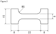
- the weld section 12 in the middle between two positions 11 of the obtained injection molded article 10 which correspond to the gates of the mold is taken as the center, and test pieces were sequentially punched from the injection molded article 10 along the weld section 12 by using a dumbbell cutter 13 to prepare a plurality of micro dumbbell shape test pieces shown in Figure 2 .
- the weld depth of the weld section positioned in the middle of the micro dumbbell shape test piece on the gate side was measured, and the ratio of the maximum depth of the weld section (D) to the maximum thickness of the micro dumbbell shape test piece (L) (in the present experimental example, 1.5 mmt), (weld ratio (D/L), was determined.
- tensilon universal tester (RTC-1225A manufactured by ORIENTEC CO., LTD.) was used, and the tensile test was carried out at a distance between chucks of 22 mm and a tensile rate of 50 mm/min to measure the maximum point stress (tensile strength).
Landscapes
- Chemical & Material Sciences (AREA)
- Manufacturing & Machinery (AREA)
- Engineering & Computer Science (AREA)
- Mechanical Engineering (AREA)
- Medicinal Chemistry (AREA)
- Chemical Kinetics & Catalysis (AREA)
- Health & Medical Sciences (AREA)
- Polymers & Plastics (AREA)
- Organic Chemistry (AREA)
- General Chemical & Material Sciences (AREA)
- Materials Engineering (AREA)
- Injection Moulding Of Plastics Or The Like (AREA)
- Addition Polymer Or Copolymer, Post-Treatments, Or Chemical Modifications (AREA)
Abstract
Description
- The present disclosure relates to an injection molded article and a method for producing the same.
- Patent Document 1 describes an ozone-resistant injection molded article comprising a perfluororesin, wherein the perfluororesin is composed of a perfluoro polymer, has an MIT value of 300,000 cycles or more, and has not more than 50 unstable end groups per 1 × 10⁶ carbon atoms in the perfluoro polymer.
- Patent Document 1: International Publication No.
WO 2003/048214 - An object of the present disclosure is to provide an injection molded article which is excellent in the abrasion resistance at 90°C, the long-time tensile creep property, the chemical solution low permeability, the rigidity on heating and the heat distortion resistance after chemical immersion, hardly makes fluorine ions dissolve out in a chemical solution, and has a beautiful appearance and a high flow length.
- According to the present disclosure, there is provided an injection molded article obtained by injection molding a copolymer using a mold provided with a gate, wherein the copolymer contains tetrafluoroethylene (TFE) unit and a fluoro(alkyl vinyl ether) (FAVE) unit, the content of the fluoro(alkyl vinyl ether) unit of the copolymer is 3.5 to 4.7% by mass with respect to the whole of the monomer units, the melt flow rate at 372°C of the copolymer is 22.0 to 35.0 g/10 min, the number of functional groups of the copolymer is 20 or less per 106 main-chain carbon atoms, and the injection molded article has a gate section corresponding to the gate of the mold, and the ratio of a maximum flow length (a) from the gate section of the injection molded article to an average value (b) of a product thickness on the maximum flow length, ((a)/(b)), is 80 to 200.
- In the injection molded article of the present disclosure, the fluoro(alkyl vinyl ether) unit of the copolymer is preferably perfluoro(propyl vinyl ether) unit.
- In the injection molded article of the present disclosure, the content of the fluoro(alkyl vinyl ether) unit of the copolymer is preferably 3.9 to 4.5% by mass with respect to the whole of the monomer units.
- In the injection molded article of the present disclosure, the melt flow rate at 372°C of the copolymer is preferably 24.2 to 30.0 g/10 min.
- In the injection molded article of the present disclosure, the melting point of the copolymer is preferably 295 to 305°C.
- It is preferable that the injection molded article of the present disclosure further has a weld section, and the ratio of a maximum depth (D) of the weld section to a maximum thickness (L) of the injection molded article, (D/L), is 0.8 or less.
- According to the present disclosure, there is provided a method for producing the above injection molded article, the method comprising: injection molding the copolymer by using an injection molding machine and the mold provided with the gate, wherein the ratio of a maximum flow length (c) from the gate section of the mold to an average value (d) of a cavity thickness of the mold on the maximum flow length, ((c)/(d)), is 80 to 200.
- In the production method of the present disclosure, the temperature of the mold is preferably 150 to 250°C.
- In the production method of the present disclosure, the cylinder temperature of the injection molding machine is preferably 350 to 420°C.
- According to the present disclosure, there can be provided an injection molded article which is excellent in the abrasion resistance at 90°C, the long-time tensile creep property, the chemical solution low permeability, the rigidity on heating and the heat distortion resistance after chemical immersion, hardly makes fluorine ions dissolve out in a chemical solution, and has a beautiful appearance and a high flow length.
-
-
Figure 1 is a diagram of a production method of a micro dumbbell shape test piece. -
Figure 2 is a diagram of the shape of a micro dumbbell shape test piece. - Hereinafter, specific embodiments of the present disclosure will be described in detail, but the present disclosure is not limited to the following embodiments.
- Patent Document 1 proposes, in particular, as an article excellent in the ozone resistance such as a piping member or a joint used in a semiconductor production apparatus, an ozone-resistant injection molded article comprising a perfluororesin, wherein the perfluororesin is composed of a perfluoro polymer, has an MIT value of 300,000 cycles or more, and has not more than 50 unstable end groups per 1 × 10⁶ carbon atoms in the perfluoro polymer. It is also described in Examples of Patent Document 1 that a cap nut of 43 mm in minimum outer diameter, 27.02 mm in internal diameter, and 30 mm in height is produced by injection molding using an injection molding machine.
- However, it is difficult to use the ozone-resistant injection molded article described in Patent Document 1 as an injection molded article having a beautiful appearance and a high flow length. For example, piping members that are used to transfer a chemical solution, such as joints, and flowmeter members for measuring the flow rate of a chemical solution often have a complicated shape, and they are required to have a beautiful appearance. When a chemical solution at a high pressure or a chemical solution at a high temperature is allowed to flow, the chemical solution at a high pressure or the chemical solution at a high temperature passes through the piping member or the flowmeter member. Since the pressure of the chemical solution frequently varies, for example, at the start of the supply of fluid, at the stop of the supply of fluid, at the change of the supply pressure of fluid, not only the durability against a chemical solution at a high pressure and a high temperature, but also the durability against the variation of pressure is also required. Therefore, there is required an injection molded article which is excellent in the abrasion resistance at high temperatures, the long-time tensile creep property, the chemical solution low permeability, the rigidity on heating and the heat distortion resistance after chemical immersion, and has a beautiful appearance and a high flow length.
- The injection molded article of the present disclosure is an injection molded article obtained by injection molding a specific copolymer using a mold provided with a gate, the injection molded article has a gate section corresponding to the gate of the mold, and the ratio of the maximum flow length (a) from the gate section of the injection molded article to the average value (b) of the product thickness on the maximum flow length, ((a)/(b)), is 80 to 200. The injection molded article of the present disclosure, due to having such a configuration, is excellent in the abrasion resistance at 90°C, the long-time tensile creep property, the chemical solution low permeability, the rigidity on heating and the heat distortion resistance after chemical immersion, hardly makes fluorine ions dissolve out in a chemical solution, and has a beautiful appearance and a high flow length.
- The injection molded article of the present disclosure has a gate section. The gate section corresponds to the gate provided in the mold used in injection molding, and is usually observed on the surface of an injection molded article as a gate mark that remains on the injection molded article after the gate and the injection molded article are separated from each other. The number of the gate section is not limited, and is preferably 1 or more, may be 4 or less, and is more preferably 1.
- The injection molded article of the present disclosure has a high flow length, and the ratio of the maximum flow length (a) from the gate section of the injection molded article to the average value (b) of the product thickness on the maximum flow length, ((a)/(b)), is 80 to 200. The ratio ((a)/(b)) is preferably 85 or more, more preferably 87 or more, still more preferably 90 or more, especially preferably 94 or more, and most preferably 100 or more, and preferably 150 or less, and more preferably 135 or less. In an injection molded article having a high ratio ((a)/(b)), forming defects such as scratches and surface delamination are likely to remain, and the smoothness is likely to deteriorate. On the other hand, it is difficult to utilize conventional injection molded articles having a low flow length as injection molded articles that are likely to have a long flow length, such as piping members that are used to transfer a chemical solution, such as joints, and flowmeter members for measuring the flow rate of a chemical solution, even when the conventional injection molded articles are excellent in the rigidity on heating and the heat distortion resistance after chemical immersion. The injection molded article of the present disclosure is excellent in the abrasion resistance at 90°C, the long-time tensile creep property, the chemical solution low permeability, the rigidity on heating and the heat distortion resistance after chemical immersion, and furthermore, has a high flow length.
- The maximum flow length (a) from the gate section refers to the distance the copolymer has flowed in a mold, and can be specified by, for example, measuring the distance between the gate section and the weld section generated at the portion where the copolymer flowed in the mold joins. Alternatively, when no weld section is present between the gate section and the edge of the injection molded article which is located farthest from the gate section, the maximum flow length from the gate section (a) can be specified by measuring the distance between the gate section and the edge of the injection molded article which is located farthest from the gate section. When a plurality of distances the copolymer has flowed in a mold can be specified, for example, when an injection molded article has a plurality of gate sections, the longest distance among the specified distances is determined as the maximum flow length (a) from the gate section.
- The ratio ((a)/(b)) can be determined by dividing the maximum flow length (a) determined as above by the average value (b) of the product thickness on the maximum flow length. The average value (b) of the product thickness on the maximum flow length can be calculated by measuring the minimum diameter of a cross section orthogonal to a line drawn to measure the maximum flow length (a) (the product thickness on the maximum flow length, when the cross section is a quadrangle, the short side) for every 2 mm along the line drawn to measure the maximum flow length, integrating the measured values, and calculating the average of the measured values.
- The injection molded article of the present disclosure usually has a weld section corresponding to a portion where a resin has flowed in a mold and joined. The weld section can usually be observed as a weld line on the surface of the injection molded article. In the present disclosure, in addition to a large weld line that can be said as a forming defect, a hardly visible weld line is also included in the weld section.
- The injection molded article of the present disclosure has a beautiful appearance and has a small maximum depth of the weld section. Thus, in the injection molded article of the present disclosure, the ratio of the maximum depth (D) of the weld section to the maximum thickness (L) of the injection molded article, (D/L), is preferably 0.8 or lower, more preferably 0.7 or lower, still more preferably 0.5 or lower, further still more preferably 0.3 or lower, and especially preferably 0.2 or lower. It can be said that as the maximum depth of the weld section is smaller, the surface of the injection molded article is smoother, and the injection molded article is more excellent in the transparency. It has also been found that as the ratio of the maximum depth (D) of the weld section to the maximum thickness (L) of the injection molded article, (D/L), is smaller, the tensile strength of the injection molded article increases significantly.
- The injection molded article of the present disclosure contains a copolymer containing tetrafluoroethylene (TFE) unit and a fluoro(alkyl vinyl ether) (FAVE) unit. The copolymer is a melt-fabricable fluororesin. Being melt-fabricable means that a polymer can be melted and processed by using a conventional processing device such as an extruder or an injection molding machine.
- Examples of the FAVE constituting the above FAVE unit include at least one selected from the group consisting of a monomer represented by the general formula (1):
CF2=CFO(CF2CFY1O)p-(CF2CF2CF2O)q-Rf (1)
- wherein Y1 represents F or CF3, and Rf represents a perfluoroalkyl group having 1 to 5 carbon atoms; p represents an integer of 0 to 5; and q represents an integer of 0 to 5, and a monomer represented by the general formula (2):
CFX=CXOCF2OR1 (2)
- wherein X is the same or different and represents H, F or CF3; R1 represents a linear or branched fluoroalkyl group having 1 to 6 carbon atoms which may contain one or two atoms of at least one type selected from the group consisting of H, Cl, Br and I, or a cyclic fluoroalkyl group having 5 or 6 carbon atoms which may contain one or two atoms of at least one type selected from the group consisting of H, Cl, Br and I.
- Among them, the above FAVE is preferably the monomer represented by the general formula (1), more preferably at least one selected from the group consisting of perfluoro(methyl vinyl ether), perfluoro(ethyl vinyl ether) (PEVE) and perfluoro(propyl vinyl ether) (PPVE), still more preferably at least one selected from the group consisting of PEVE and PPVE, and particularly preferably PPVE.
- The content of the FAVE unit of the copolymer is 3.5 to 4.7% by mass with respect to the whole of the monomer units. The content of the FAVE unit of the copolymer is preferably 3.6% by mass or higher, more preferably 3.7% by mass or higher, still more preferably 3.8% by mass or higher, and especially preferably 3.9% by mass or higher, and preferably 4.6% by mass or lower, and more preferably 4.5% by mass or lower. When the content of the FAVE unit of the copolymer is too high, the rigidity on heating, the long-time tensile creep property and the chemical solution low permeability of the injection molded article deteriorate. When the content of the FAVE unit of the copolymer is too low, the abrasion resistance at 90°C and the heat distortion resistance after chemical immersion of the injection molded article deteriorate.
- The content of the TFE unit of the copolymer is, with respect to the whole of the monomer units, preferably 95.3 to 96.5% by mass, more preferably 95.4% by mass or higher, and still more preferably 95.5% by mass or higher, and more preferably 96.4% by mass or lower, still more preferably 96.3% by mass or lower, further still more preferably 96.2% by mass or lower, and especially preferably 96.1% by mass or lower. When the content of the TFE unit of the copolymer is too low, the rigidity on heating, the long-time tensile creep property and the chemical solution low permeability of the injection molded article may deteriorate. When the content of the TFE unit of the copolymer is too high, the abrasion resistance at 90°C and the heat distortion resistance after chemical immersion of the injection molded article may deteriorate.
- In the present disclosure, the content of each monomer unit in the copolymer is measured by a 19F-NMR method.
- The copolymer can also contain a monomer unit originated from a monomer copolymerizable with TFE and FAVE. In this case, the content of the monomer unit copolymerizable with TFE and FAVE is, with respect to the whole of the monomer units of the copolymer, preferably 0 to 1.2% by mass, more preferably 0.05 to 0.5% by mass, and still more preferably 0.1 to 0.3% by mass.
- The monomers copolymerizable with TFE and FAVE may include hexafluoropropylene (HFP), vinyl monomers represented by CZ1Z2=CZ3(CF2)nZ4 wherein Z1, Z2 and Z3 are identical or different, and represent H or F; Z4 represents H, F or Cl; and n represents an integer of 2 to 10, and alkyl perfluorovinyl ether derivatives represented by CF2=CF-OCH2-Rf1 wherein Rf1 represents a perfluoroalkyl group having 1 to 5 carbon atoms. Among these, HFP is preferred.
- The copolymer is preferably at least one selected from the group consisting of a copolymer consisting only of the TFE unit and the FAVE unit, and TFE/HFP/FAVE copolymer, and is more preferably a copolymer consisting only of the TFE unit and the FAVE unit.
- The melt flow rate (MFR) of the copolymer is 22.0 to 35.0 g/10 min. The MFR of the copolymer is preferably 23.0 g/10 min or higher, and more preferably 24.0 g/10 min or higher, and preferably 33.0 g/10 min or lower, more preferably 32.0 g/10 min or lower, still more preferably 31.0 g/10 min or lower, and especially preferably 30.0 g/10 min or lower. When the MFR of the copolymer is too low, not only the chemical solution low permeability and the appearance of the injection molded article deteriorate, but also an injection molded article having a flow length may not be obtained. When the MFR of the copolymer is too high, the abrasion resistance at 90°C and the heat distortion resistance after chemical immersion of the injection molded article deteriorate.
- In the present disclosure, the MFR is a value obtained as a mass (g/10 min) of the polymer flowing out from a nozzle of 2.1 mm in inner diameter and 8 mm in length per 10 min at 372°C under a load of 5 kg using a melt indexer, according to ASTM D1238.
- The MFR can be regulated by regulating the kind and amount of a polymerization initiator to be used in polymerization of monomers, the kind and amount of a chain transfer agent, and the like.
- In the present disclosure, the number of functional groups per 106 main-chain carbon atoms of the copolymer is 20 or less, preferably 15 or less, more preferably 10 or less, and still more preferably less than 6. Due to that the number of functional groups of the copolymer is within the above range, the chemical solution low permeability of the injection molded article can be improved, and the amount of fluorine ions dissolving out from the injection molded article in a chemical solution can be significantly reduced.
- For identification of the kind of the functional groups and measurement of the number of the functional groups, infrared spectroscopy can be used.
- The number of the functional groups is measured, specifically, by the following method. First, the copolymer is formed by cold press to prepare a film of 0.25 to 0.30 mm in thickness. The film is analyzed by Fourier transform infrared spectroscopy to obtain an infrared absorption spectrum of the copolymer, and a difference spectrum against a base spectrum that is completely fluorinated and has no functional groups is obtained. From an absorption peak of a specific functional group observed on this difference spectrum, the number N of the functional group per 1×10⁶ carbon atoms in the copolymer is calculated according to the following formula (A).

- I: absorbance
- K: correction factor
- t: thickness of film (mm)
- For reference, for some functional groups, the absorption frequency, the molar absorption coefficient and the correction factor are shown in Table 1. Then, the molar absorption coefficients are those determined from FT-IR measurement data of low molecular model compounds.
-
Table 1 Functional Group Absorption Frequency (cm-1) Molar Extinction Coefficient (l/cm/mol) Correction Factor Model Compound -COF 1883 600 388 C7F15COF -COOH free 1815 530 439 H(CF2)6COOH -COOH bonded 1779 530 439 H(CF2)6COOH -COOCH3 1795 680 342 C7F15COOCH3 -CONH2 3436 506 460 C7H15CONH2 -CH2OH2, -OH 3648 104 2236 C7H15CH2OH -CF2H 3020 8.8 26485 H(CF2CF2)3CH2OH -CF=CF2 1795 635 366 CF2=CF2 - Absorption frequencies of -CH2CF2H, -CH2COF, -CH2COOH, -CH2COOCH3 and -CH2CONH2 are lower by a few tens of kaysers (cm-1) than those of -CF2H, -COF, -COOH free and -COOH bonded, -COOCH3 and -CONH2 shown in the Table, respectively.
- For example, the number of the functional group -COF is the total of the number of a functional group determined from an absorption peak having an absorption frequency of 1,883 cm-1 derived from -CF2COF and the number of a functional group determined from an absorption peak having an absorption frequency of 1,840 cm-1 derived from -CH2COF.
- The functional groups are ones present on main chain terminals or side chain terminals of the copolymer, and ones present in the main chain or the side chains. The number of the functional groups may be the total of numbers of -CF=CF2, -CF2H, -COF, -COOH, -COOCH3, -CONH2 and -CH2OH.
- The functional groups are introduced to the copolymer by, for example, a chain transfer agent or a polymerization initiator used for production of the copolymer. For example, in the case of using an alcohol as the chain transfer agent, or a peroxide having a structure of -CH2OH as the polymerization initiator, -CH2OH is introduced on the main chain terminals of the copolymer. Alternatively, the functional group is introduced on the side chain terminal of the copolymer by polymerizing a monomer having the functional group.
- The copolymer satisfying the above range regarding the number of functional groups can be obtained by subjecting the copolymer to a fluorination treatment. That is, the copolymer contained in the injection molded article of the present disclosure is preferably one which is subjected to the fluorination treatment. Further, the copolymer contained in the injection molded article of the present disclosure preferably has -CF3 terminal groups.
- The melting point of the copolymer is preferably 295 to 315°C, more preferably 300°C or higher, still more preferably 301°C or higher, and especially preferably 302°C or higher, and more preferably 310°C or lower, and still more preferably 305°C or lower. Due to that the melting point is in the above range, the abrasion resistance at 90°C, the long-time tensile creep property, the chemical solution low permeability, the rigidity on heating and the heat distortion resistance after chemical immersion are further improved, even when the flow length of the injection molded article is high.
- In the present disclosure, the melting point can be measured by using a differential scanning calorimeter [DSC].
- The methyl ethyl ketone (MEK) permeability of the injection molded article of the present disclosure is preferably 74.0 g/m2 or lower. For example, when being used to allow a chemical solution to flow, the injection molded article of the present disclosure can highly suppress the permeation of a chemical solution such as MEK to the outside.
- In the present disclosure, the MEK permeability can be measured under the condition of a temperature of 60°C and for 60 days. Specific measurement of the MEK permeability can be carried out by a method described in Examples.
- In the injection molded article of the present disclosure, the amount of fluorine ions dissolving out therefrom detected by a hydrogen peroxide solution immersion test is, in terms of mass, preferably 5.0 ppm or lower, more preferably 4.0 ppm or lower and still more preferably 3.0 ppm or lower. When the injection molded article of the present disclosure is used as, for example, piping members that are used to transfer a chemical solution, such as joints, and flowmeter members for measuring the flow rate of a chemical solution, the contamination of the chemical solution by fluorine ions can be highly suppressed.
- In the present disclosure, the hydrogen peroxide solution immersion test can be carried out by preparing a test piece having a weight corresponding to that of 30 formed articles (40 mm × 40 mm × 0.5 mmt), immersing the test piece in 50 g of a 3% by weight aqueous hydrogen peroxide solution, heating the test piece at 90°C for 20 hours, and further heating the test piece at 121°C for 3 hours.
- The injection molded article of the present disclosure may contain other components such as fillers, plasticizers, processing aids, mold release agents, pigments, flame retarders, lubricants, light stabilizers, weathering stabilizers, electrically conductive agents, antistatic agents, ultraviolet absorbents, antioxidants, foaming agents, perfumes, oils, softening agents and dehydrofluorination agents.
- Examples of the fillers include silica, kaolin, clay, organo clay, talc, mica, alumina, calcium carbonate, calcium terephthalate, titanium oxide, calcium phosphate, calcium fluoride, lithium fluoride, crosslinked polystyrene, potassium titanate, carbon, boron nitride, carbon nanotube and glass fiber. The electrically conductive agents include carbon black. The plasticizers include dioctyl phthalate and pentaerythritol. The processing aids include carnauba wax, sulfone compounds, low molecular weight polyethylene and fluorine-based auxiliary agents. The dehydrofluorination agents include organic oniums and amidines.
- As the above-mentioned other components, other polymers other than the copolymer may be used. The other polymers include fluororesins other than the copolymer, fluoroelastomer, and non-fluorinated polymers.
- The copolymer contained in the injection molded article of the present disclosure can be produced by a polymerization method such as suspension polymerization, solution polymerization, emulsion polymerization or bulk polymerization. The polymerization method is preferably emulsion polymerization or suspension polymerization. In these polymerization methods, conditions such as temperature and pressure, and a polymerization initiator and other additives can suitably be set depending on the formulation and the amount of the copolymer.
- As the polymerization initiator, an oil-soluble radical polymerization initiator, or a water-soluble radical polymerization initiator may be used.
- The oil-soluble radical polymerization initiator may be a known oil-soluble peroxide, and examples thereof typically include:
- dialkyl peroxycarbonates such as di-n-propyl peroxydicarbonate, diisopropyl peroxydicarbonate, di-sec-butyl peroxydicarbonate and di-2-ethoxyethyl peroxydicarbonate;
- peroxyesters such as t-butyl peroxyisobutyrate and t-butyl peroxypivalate;
- dialkyl peroxides such as di-t-butyl peroxide; and
- di[fluoro(or fluorochloro)acyl] peroxides.
- The di[fluoro(or fluorochloro)acyl] peroxides include diacyl peroxides represented by [(RfCOO)-]2 wherein Rf is a perfluoroalkyl group, an ω-hydroperfluoroalkyl group or a fluorochloroalkyl group.
- Examples of the di[fluoro(or fluorochloro)acyl] peroxides include di(ω-hydro-dodecafluorohexanoyl) peroxide, di(ω-hydro-tetradecafluoroheptanoyl) peroxide, di(ω-hydro-hexadecafluorononanoyl) peroxide, di(perfluoropropionyl) peroxide, di(perfluorobutyryl) peroxide, di(perfluorovaleryl) peroxide, di(perfluorohexanoyl) peroxide, di(perfluoroheptanoyl) peroxide, di(perfluorooctanoyl) peroxide, di(perfluorononanoyl) peroxide, di(ω-chloro-hexafluorobutyryl) peroxide, di(ω-chloro-decafluorohexanoyl) peroxide, di(ω-chloro-tetradecafluorooctanoyl) peroxide, ω-hydrododecafluoroheptanoyl-ω-hydrohexadecafluorononanoyl peroxide, ω-chloro-hexafluorobutyryl-ω-chloro-decafluorohexanoyl peroxide, ω-hydrododecafluoroheptanoyl-perfluorobutyryl peroxide, di(dichloropentafluorobutanoyl) peroxide, di(trichlorooctafluorohexanoyl) peroxide, di(tetrachloroundecafluorooctanoyl) peroxide, di(pentachlorotetradecafluorodecanoyl) peroxide and di(undecachlorotriacontafluorodocosanoyl) peroxide.
- The water-soluble radical polymerization initiator may be a known water-soluble peroxide, and examples thereof include ammonium salts, potassium salts and sodium salts of persulfuric acid, perboric acid, perchloric acid, perphosphoric acid, percarbonic acid and the like, organic peroxides such as disuccinoyl peroxide and diglutaroyl peroxide, and t-butyl permaleate and t-butyl hydroperoxide. A reductant such as a sulfite salt may be combined with a peroxide and used, and the amount thereof to be used may be 0.1 to 20 times with respect to the peroxide.
- In the polymerization, a surfactant, a chain transfer agent and a solvent may be used, which are conventionally known.
- The surfactant may be a known surfactant, for example, nonionic surfactants, anionic surfactants and cationic surfactants may be used. Among these, fluorine-containing anionic surfactants are preferred, and more preferred are linear or branched fluorine-containing anionic surfactants having 4 to 20 carbon atoms, which may contain an ether bond oxygen (that is, an oxygen atom may be inserted between carbon atoms). The amount of the surfactant to be added (with respect to water in the polymerization) is preferably 50 to 5,000 ppm.
- Examples of the chain transfer agent include hydrocarbons such as ethane, isopentane, n-hexane and cyclohexane; aromatics such as toluene and xylene; ketones such as acetone; acetate esters such as ethyl acetate and butyl acetate; alcohols such as methanol and ethanol; mercaptans such as methylmercaptan; and halogenated hydrocarbons such as carbon tetrachloride, chloroform, methylene chloride and methyl chloride. The amount of the chain transfer agent to be added may vary depending on the chain transfer constant value of the compound to be used, but is usually in the range of 0.01 to 20% by mass with respect to the solvent in the polymerization.
- The solvent may include water and mixed solvents of water and an alcohol.
- In the suspension polymerization, in addition to water, a fluorosolvent may be used. The fluorosolvent may include hydrochlorofluoroalkanes such as CH3CClF2, CH3CCl2F, CF3CF2CCl2H and CF2ClCF2CFHCl; chlorofluoroalaknes such as CF2ClCFClCF2CF3 and CF3CFClCFClCF3; hydrofluroalkanes such as CF3CFHCFHCF2CF2CF3, CF2HCF2CF2CF2CF2H and CF3CF2CF2CF2CF2CF2CF2H; hydrofluoroethers such as CH3OC2F5, CH3OC3F5CF3CF2CH2OCHF2, CF3CHFCF2OCH3, CHF2CF2OCH2F, (CF3)2CHCF2OCH3, CF3CF2CH2OCH2CHF2 and CF3CHFCF2OCH2CF3; and perfluoroalkanes such as perfluorocyclobutane, CF3CF2CF2CF3, CF3CF2CF2CF2CF3 and CF3CF2CF2CF2CF2CF3, and among these, perfluoroalkanes are preferred. The amount of the fluorosolvent to be used is, from the viewpoint of the suspensibility and the economic efficiency, preferably 10 to 100% by mass with respect to an aqueous medium.
- The polymerization temperature is not limited, and may be 0 to 100°C. The polymerization pressure is suitably set depending on other polymerization conditions to be used such as the kind, the amount and the vapor pressure of the solvent, and the polymerization temperature, but may usually be 0 to 9.8 MPaG.
- In the case of obtaining an aqueous dispersion containing the copolymer by the polymerization reaction, the copolymer can be recovered by coagulating, cleaning and drying the copolymer contained in the aqueous dispersion. Then in the case of obtaining the copolymer as a slurry by the polymerization reaction, the copolymer can be recovered by taking out the slurry from a reaction container, and cleaning and drying the slurry. The copolymer can be recovered in a shape of powder by the drying.
- The copolymer obtained by the polymerization may be formed into pellets. A method of forming into pellets is not limited, and a conventionally known method can be used. Examples thereof include methods of melt extruding the copolymer by using a single-screw extruder, a twin-screw extruder or a tandem extruder and cutting the resultant into a predetermined length to form the copolymer into pellets. The extrusion temperature in the melt extrusion needs to be varied depending on the melt viscosity and the production method of the copolymer, and is preferably the melting point of the copolymer + 20°C to the melting point of the copolymer + 140°C. A method of cutting the copolymer is not limited, and there can be adopted a conventionally known method such as a strand cut method, a hot cut method, an underwater cut method, or a sheet cut method. Volatile components in the obtained pellets may be removed by heating the pellets (degassing treatment). Alternatively, the obtained pellets may be treated by bringing the pellets into contact with hot water of 30 to 200°C, steam of 100 to 200°C or hot air of 40 to 200°C.
- Alternatively, the copolymer obtained by the polymerization may be subjected to fluorination treatment. The fluorination treatment can be carried out by bringing the copolymer having been subjected to no fluorination treatment into contact with a fluorine-containing compound. By the fluorination treatment, thermally unstable functional groups of the copolymer, such as -COOH, -COOCH3, -CH2OH, -COF, -CF=CF2 and -CONH2, and thermally relatively stable functional groups thereof, such as -CF2H, can be converted to thermally very stable -CF3. Consequently, the total number (number of functional groups) of -COOH, -COOCH3, -CH2OH, -COF, -CF=CF2, - CONH2 and -CF2H of the copolymer can easily be controlled in the above-mentioned range.
- The fluorine-containing compound is not limited, but includes fluorine radical sources generating fluorine radicals under the fluorination treatment condition. The fluorine radical sources include F2 gas, CoF3, AgF2, UF6, OF2, N2F2, CF3OF, halogen fluorides (for example, IF5 and ClF3).
- The fluorine radical source such as F2 gas may be, for example, one having a concentration of 100%, but from the viewpoint of safety, the fluorine radical source is preferably mixed with an inert gas and diluted therewith to 5 to 50% by mass, and then used; and it is more preferably to be diluted to 15 to 30% by mass. The inert gas includes nitrogen gas, helium gas and argon gas, but from the viewpoint of the economic efficiency, nitrogen gas is preferred.
- The condition of the fluorination treatment is not limited, and the copolymer in a melted state may be brought into contact with the fluorine-containing compound, but the fluorination treatment can be carried out usually at a temperature of not higher than the melting point of the copolymer, preferably at 20 to 240°C and more preferably at 100 to 220°C. The fluorination treatment is carried out usually for 1 to 30 hours and preferably 5 to 25 hours. The fluorination treatment is preferred which brings the copolymer having been subjected to no fluorination treatment into contact with fluorine gas (F2 gas).
- The injection molded article of the present disclosure can be produced by the method for injection molding the copolymer obtained as above using an injection molding machine and a mold provided with a gate. According to the production method of the present disclosure, there can be produced an injection molded article which is excellent in the abrasion resistance at 90°C, the long-time tensile creep property, the chemical solution low permeability, the rigidity on heating and the heat distortion resistance after chemical immersion, hardly makes fluorine ions dissolve out in a chemical solution, and has a beautiful appearance and a high flow length. Further, since the production method of the present disclosure comprises forming the above copolymer, an injection molded article having a high flow length and a complicated shape can easily be produced by using the production method of the present disclosure, and for example, injection molded articles such as housings of flowmeters, housings of valves, and filter cages can easily be produced.
- The shape of the copolymer to be supplied into an injection molding machine is not limited, and a copolymer in a shape of powder, pellet, or the like can be used.
- A known injection molding machine can be used. The copolymer injected from a nozzle of an injection molding machine usually passes through a sprue, a runner, and a gate, flows into a mold cavity, and is filled in the mold cavity. In the mold used for injection molding, a runner and a gate are formed, and a mold cavity for forming an injection molded article is formed.
- The shape of the sprue is not limited, and may be a circle, a rectangle, a trapezoid, or the like. The shape of the runner is not limited, and may be a circle, a rectangle, a trapezoid, or the like. The runner type is not limited, and may be a cold runner or a hot runner. The gate type is not limited, and may be a direct gate, a side gate, a submarine gate, or the like. The number of gates to the mold cavity is not limited. Any of the mold having a single-gate structure and the mold having a multi-gate structure may be used. The number of mold cavities of the mold (number of cavities) is preferably 1 to 64.
- Regarding the flow length of the copolymer from the gate, a mold having a ratio of the maximum flow length (c) from the gate section of the mold to the average value (d) of the cavity thickness of the mold on the maximum flow length, ((c)/(d)), of 80 to 200 is used in the injection molding. The ratio ((c)/(d)) is preferably 85 or more, more preferably 87 or more, still more preferably 90 or more, especially preferably 94 or more, and most preferably 100 or more, and preferably 150 or less, and more preferably 135 or less.
- There are tendencies that, as the cavity of the mold to be used in the injection molding has more parts having a small thickness, that is, as the ratio ((c)/(d)) is higher, the flow length of the copolymer is unlikely to be longer, so that it is more difficult to obtain a large injection molded article having a lot of thin-wall parts (that is, an injection molded article having a high ratio ((a)/(b))), and furthermore, the appearance of the injection molded article to be obtained deteriorates and the transparency thereof also deteriorates. On the other hand, in the conventional injection molded article having a high ratio ((a)/(b)), there is room for improvement in the abrasion resistance at 90°C, the long-time tensile creep property, the chemical solution low permeability, the rigidity on heating and the heat distortion resistance after chemical immersion, even if the appearance is excellent. Further, an injection molded article which hardly makes fluorine ions dissolve out in a chemical solution is also desired. The production method of the present disclosure, due to having the above configuration, can produce an injection molded article which has a ratio ((a)/(b)) within the range as described above, and furthermore, is excellent in the abrasion resistance at 90°C, the long-time tensile creep property, the chemical solution low permeability, the rigidity on heating and the heat distortion resistance after chemical immersion, hardly makes fluorine ions dissolve out in a chemical solution, and has a beautiful appearance.
- In the production method of the present disclosure, due to that there can be produced an injection molded article which is excellent in the abrasion resistance at 90°C, the long-time tensile creep property, the chemical solution low permeability, the rigidity on heating and the heat distortion resistance after chemical immersion, hardly makes fluorine ions dissolve out in a chemical solution, and has a further beautiful appearance, the temperature of the mold is preferably 150 to 250°C, and more preferably 170°C or higher, and more preferably 230°C or lower, and still more preferably 200°C or lower.
- In the production method of the present disclosure, due to that there can be produced an injection molded article which is excellent in the abrasion resistance at 90°C, the long-time tensile creep property, the chemical solution low permeability, the rigidity on heating and the heat distortion resistance after chemical immersion, and has a further beautiful appearance, the temperature of the cylinder provided in an injection molding machine is preferably 350 to 420°C, more preferably 370°C or higher, and more preferably 400°C or lower.
- The injection molded article of the present disclosure can be used in various applications. The injection molded article of the present disclosure may be, for example, nuts, bolts, joints, films, bottles, gaskets, tubes, hoses, pipes, valves, sheets, seals, packings, tanks, rollers, containers, cocks, connectors, filter housings, filter cages, flowmeters, pumps, wafer carrier, or wafer boxes.
- Due to that the injection molded article of the present disclosure is excellent in the abrasion resistance at 90°C, the long-time tensile creep property, the chemical solution low permeability, the rigidity on heating and the heat distortion resistance after chemical immersion, hardly makes fluorine ions dissolve out in a chemical solution, and has a beautiful appearance and a high flow length, the injection molded article can suitably be utilized for nuts, bolts, joints, packings, valves, cocks, connectors, filter housings, filter cages, flowmeters, pumps, and the like. For example, the injection molded article of the present disclosure can suitably be utilized as piping members (in particular, housings of valves and filter cages) to be used in the transfer of chemical solutions, and flowmeter housings provided with flow paths for chemical solutions in flowmeters. The piping members and flowmeter housings of the present disclosure are excellent in the abrasion resistance at 90°C, the long-time tensile creep property, the chemical solution low permeability, the rigidity on heating and the heat distortion resistance after chemical immersion, hardly make fluorine ions dissolve out in a chemical solution, and have a beautiful appearance. Hence, the piping members and flowmeter housings of the present disclosure can be suitably used also in the measurement of the flow rate of a chemical solution at about 80°C, and are hardly damaged even when stresses are repeatedly applied according to the start of the flow, the stop of the flow, and the change of the flow rate of the chemical solution.
- Due to that the injection molded article of the present disclosure is excellent in the abrasion resistance at 90°C, the long-time tensile creep property, the chemical solution low permeability, the rigidity on heating and the heat distortion resistance after chemical immersion, hardly makes fluorine ions dissolve out in a chemical solution, and has a beautiful appearance and a high flow length, it can be suitably utilized as members to be compressed such as gaskets and packings.
- Due to that the injection molded article of the present disclosure is excellent in the abrasion resistance at 90°C, the long-time tensile creep property, the chemical solution low permeability, the rigidity on heating and the heat distortion resistance after chemical immersion, hardly makes fluorine ions dissolve out in a chemical solution, and has a beautiful appearance and a high flow length, it can be suitably utilized as bottles or tubes. The bottles or tubes of the present disclosure are hardly damaged during use.
- The injection molded article of the present disclosure of the present disclosure is excellent in the abrasion resistance at 90°C, the long-time tensile creep property, the chemical solution low permeability, the rigidity on heating and the heat distortion resistance after chemical immersion, hardly makes fluorine ions dissolve out in a chemical solution, and has a beautiful appearance and a high flow length. Therefore, the injection molded article of the present disclosure can suitably be utilized for housings of valves and valves. The valves of the present disclosure of the present disclosure are excellent in the abrasion resistance at 90°C, the long-time tensile creep property, the chemical solution low permeability, the rigidity on heating and the heat distortion resistance after chemical immersion, and hardly make fluorine ions dissolve out in a chemical solution. The valves of the present disclosure, due to having a high elastic modulus even at high temperatures, can be suitably used to control fluid, for example, at 80°C or higher.
- Although the embodiments have been described above, it will be understood that various changes in form and details are possible without departing from the gist and scope of the claims.
- Next, embodiments of the present disclosure will be described with reference to examples, but the present disclosure is not intended to be limited by these examples.
- The numerical values of the Examples were measured by the following methods.
- The content of each monomer unit was measured by an NMR analyzer (for example, manufactured by Bruker BioSpin GmbH, AVANCE 300, high-temperature probe).
- The polymer was made to flow out from a nozzle of 2.1 mm in inner diameter and 8 mm in length at 372°C under a load of 5 kg by using a Melt Indexer G-01 (manufactured by Toyo Seiki Seisaku-sho, Ltd.) according to ASTM D1238, and the mass (g/10 min) of the polymer flowing out per 10 min was determined.
- The polymer was heated, as a first temperature raising step at a temperature-increasing rate of 10°C/min from 200°C to 350°C, then cooled at a cooling rate of 10°C/min from 350°C to 200°C, and then again heated, as second temperature raising step, at a temperature-increasing rate of 10°C/min from 200°C to 350°C by using a differential scanning calorimeter (trade name: X-DSC7000, manufactured by Hitachi High-Tech Science Corp.); and the melting point was determined from a melting curve peak observed in the second temperature raising step.
- Pellets of the copolymer was formed by cold press into a film of 0.25 to 0.30 mm in thickness. The film was 40 times scanned and analyzed by a Fourier transform infrared spectrometer [FT-IR (Spectrum One, manufactured by PerkinElmer, Inc.)] to obtain an infrared absorption spectrum, and a difference spectrum against a base spectrum that is completely fluorinated and has no functional groups is obtained. From an absorption peak of a specific functional group observed on this difference spectrum, the number N of the functional group per 1×10⁶ carbon atoms in the sample was calculated according to the following formula (A).

- I: absorbance
- K: correction factor
- t: thickness of film (mm)
- Regarding the functional groups in the present disclosure, for reference, the absorption frequency, the molar absorption coefficient and the correction factor are shown in Table 2. The molar absorption coefficients are those determined from FT-IR measurement data of low molecular model compounds.
-
Table 2 Functional Group Absorption Frequency (cm-1) Molar Extinction Coefficient (l/cm/mol) Correction Factor Model Compound -COF 1883 600 388 C7F15COF -COOH free 1815 530 439 H(CF2)6COOH -COOH bonded 1779 530 439 H(CF2)6COOH -COOCH3 1795 680 342 C7F15COOCH3 -CONH2 3436 506 460 C7H15CONH2 -CH2OH2, -OH 3648 104 2236 C7H15CH2OH -CF2H 3020 8.8 26485 H(CF2CF2)3CH2OH -CF=CF2 1795 635 366 CF2=CF2 - 51.8 L of pure water was charged in a 174 L-volume autoclave; nitrogen replacement was sufficiently carried out; thereafter, 40.9 kg of perfluorocyclobutane, 2.37 kg of perfluoro(propyl vinyl ether) (PPVE) and 1.47 kg of methanol were charged; and the temperature in the system was held at 35°C and the stirring speed was held at 200 rpm. Then, tetrafluoroethylene (TFE) was introduced under pressure up to 0.64 MPa, and thereafter 0.103 kg of a 50% methanol solution of di-n-propyl peroxydicarbonate was charged to initiate polymerization. Since the pressure in the system decreased along with the progress of the polymerization, TFE was continuously supplied to make the pressure constant, and 0.052 kg of PPVE was additionally charged for every 1 kg of TFE supplied. The polymerization was finished at the time when the amount of TFE additionally charged reached 40.9 kg. Unreacted TFE was released to return the pressure in the autoclave to the atmospheric pressure, and thereafter, an obtained reaction product was washed with water and dried to thereby obtain 43.0 kg of a powder.
- The obtained powder was melt extruded at 360°C by a screw extruder (trade name: PCM46, manufactured by Ikegai Corp.) to thereby obtain pellets of a TFE/PPVE copolymer. By using the obtained pellets, the PPVE content was measured by the above-mentioned method.
- The obtained pellets were put in a vacuum vibration-type reactor VVD-30 (manufactured by Okawara MFG. Co., Ltd.), and heated to 210°C. After vacuumizing, F2 gas diluted to 20% by volume with N2 gas was introduced to the atmospheric pressure. 0.5 hour after the F2 gas introduction, vacuumizing was once carried out and the F2 gas was again introduced. Further, 0.5 hour thereafter, vacuumizing was again carried out and F2 gas was again introduced. Thereafter, while the above operation of the F2 gas introduction and the vacuumizing was carried out once every 1 hour, the reaction was carried out at a temperature of 210°C for 10 hours. After the reaction was finished, the reactor interior was replaced sufficiently by N2 gas to finish the fluorination reaction. By using the fluorinated pellets, the above physical properties were measured by the methods described above.
- Fluorinated pellets were obtained as in Synthesis Example 1, except for changing the charged amount of PPVE to 1.17 kg, changing the charged amount of methanol to 3.87 kg, and adding 0.031 kg of PPVE for every 1 kg of TFE supplied, to thereby obtain 42.2 kg of a dry powder.
- Fluorinated pellets were obtained as in Synthesis Example 1, except for changing the charged amount of PPVE to 1.73 kg, changing the charged amount of methanol to 4.70 kg, and adding 0.041 kg of PPVE for every 1 kg of TFE supplied, to thereby obtain 42.6 kg of a dry powder.
- Fluorinated pellets were obtained as in Synthesis Example 1, except for changing the charged amount of PPVE to 1.92 kg, changing the charged amount of methanol to 4.79 kg, changing the charged amount of the 50% methanol solution of di-n-propyl peroxydicarbonate to 0.051 kg, and adding 0.044 kg of PPVE for every 1 kg of TFE supplied, to thereby obtain 42.7 kg of a dry powder.
- Fluorinated pellets were obtained as in Synthesis Example 1, except for changing the charged amount of PPVE to 2.05 kg, changing the charged amount of methanol to 2.12 kg, adding 0.046 kg of PPVE for every 1 kg of TFE supplied, changing the raised temperature of the vacuum vibration-type reactor to 160°C, and changing the reaction condition to at 160°C and for 5 hours, to thereby obtain 42.8 kg of a dry powder.
- Fluorinated pellets were obtained as in Synthesis Example 1, except for changing the charged amount of PPVE to 1.73 kg, changing the charged amount of methanol to 2.27 kg, and adding 0.041 kg of PPVE for every 1 kg of TFE supplied, to thereby obtain 42.6 kg of a dry powder.
- Fluorinated pellets were obtained as in Synthesis Example 1, except for changing the charged amount of PPVE to 1.79 kg, changing the charged amount of methanol to 6.61 kg, changing the charged amount of the 50% methanol solution of di-n-propyl peroxydicarbonate to 0.051 kg, and adding 0.042 kg of PPVE for every 1 kg of TFE supplied, to thereby obtain 41.0 kg of a dry powder.
- Fluorinated pellets were obtained as in Synthesis Example 1, except for changing the charged amount of PPVE to 2.05 kg, changing the charged amount of methanol to 2.12 kg, and adding 0.046 kg of PPVE for every 1 kg of TFE supplied, to thereby obtain 42.8 kg of a dry powder.
- Fluorinated pellets were obtained as in Synthesis Example 1, except for changing the charged amount of PPVE to 2.11 kg, changing the charged amount of methanol to 2.09 kg, and adding 0.047 kg of PPVE for every 1 kg of TFE supplied, to thereby obtain 42.8 kg of a dry powder.
- By using the pellets obtained in Synthesis Examples, the above physical properties were measured by the methods described above. The results are shown in Table 3.
-
Table 3 PPVE content MFR Number of functional groups Melting point (% by mass) (g/10 min) (number/C106) (°C) Synthesis Example 1 4.9 30.4 <6 302 Synthesis Example 2 3.0 26.6 <6 310 Synthesis Example 3 3.9 48.3 < 6 305 Synthesis Example 4 4.2 16.2 <6 304 Synthesis Example 5 4.4 29.0 46 304 Synthesis Example 6 3.9 24.2 <6 305 Synthesis Example 7 4.0 25.0 < 6 305 Synthesis Example 8 4.4 29.0 < 6 304 Synthesis Example 9 4.5 30.0 <6 304 - The description of "<6" in Table 3 means that the number of functional groups is less than 6.
- By using the pellets obtained above, sheet-shape injection molded articles each having different shapes were prepared by the following method. The obtained sheet-shape injection molded articles were evaluated. The results are shown in Table 4.
- The copolymer was injection molded by using an injection molding machine (SE50EV-A, manufactured by Sumitomo Heavy Industries, Ltd.) set at a cylinder temperature of 400°C, a mold temperature of 200°C and an injection speed of 20 mm/s. The mold used was a mold (4 cavities of 40 mm × 40 mm × 0.5 mmt, side gate) made of HPM38.
- The copolymer was injection molded by using an injection molding machine (SE50EV-A, manufactured by Sumitomo Heavy Industries, Ltd.) set at a cylinder temperature of 380°C, a mold temperature of 180°C and an injection speed of 10 mm/s. The mold used was a mold (155 mm × 100 mm × 2 mmt, film gate) Cr plated on HPM38.
- From the sheet-shape injection molded article (155 mm × 100 mm × 2 mmt), a test piece of 10 cm × 10 cm was cut out. The prepared test piece was fixed on a test bench of a Taber abrasion tester (No. 101 Taber type abrasion tester with an option, manufactured by YASUDA SEIKI SEISAKUSHO, LTD.) and the abrasion test was carried out at a test piece surface temperature of 90°C and a load of 500 g, using an abrasion wheel CS-10 (rotationally polished in 20 rotations with an abrasive paper #240) and at a rotation rate of 60 rpm by using the Taber abrasion tester. The weight of the test piece after 1,000 rotations was measured, and the same test piece was further subjected to the test of 5,000 rotations and thereafter, the weight thereof was measured. The abrasion loss was determined by the following formula.

- M1: the weight of the test piece after the 1,000 rotations (mg)
- M2: the weight of the test piece after the 5,000 rotations (mg)
- After the sheet-shape injection molded article (155 mm × 100 mm × 2 mmt) was allowed to stand at 60°C for 24 hours, a test piece of 80 × 10 mm was cut out from the injection molded article and heated in an electric furnace at 100°C for 20 hours. Except for using the obtained test piece, the test was carried out according to a method described in JIS K-K 7191-1 using a heat distortion tester (manufactured by YASUDA SEIKI SEISAKUSHO, LTD.) under the conditions of at a test temperature of 30 to 150°C, a temperature-increasing rate of 120°C/hour, a bending stress of 1.8 MPa and a flatwise method. The load deflection rate was determined by the following formula. A sheet having a low load deflection rate at 80°C is excellent in the rigidity at high temperatures.

- a1: the test piece thickness before test (mm)
- a2: the amount of deflection at 80°C (mm)
- The sheet-shape injection molded article (155 mm × 100 mm × 2 mmt) was punched out by using a rectangular dumbbell of 13.5 mm × 38 mm to obtain three test pieces. A notch was formed on the middle of a long side of the each obtained test piece according to ASTM D1693 by a blade of 19 mm × 0.45 mm. Three notched test pieces and 25 g of 3% by weight aqueous hydrogen peroxide solution were put in a 100-mL polypropylene-made bottle, and heated in an electric furnace at 100°C for 20 hours; and thereafter, the notched test pieces were taken out. Then, the three notched test pieces obtained were mounted on a stress crack test jig according to ASTM D1693, and heated in an electric furnace at 100°C for 2 hours; thereafter, the notches and their vicinities were visually observed and the number of cracks was counted. A sheet having no crack generated is excellent in the heat distortion resistance even after immersion in a chemical solution.
- Good: the number of cracks was 0
- Poor: the number of cracks was 1 or more
- The tensile creep strain was measured by using TMA-7100 manufactured by Hitachi High-Tech Science Corporation. From the sheet-shape injection molded article (40 mm × 40 mm × 0.5 mmt), a sample of 2 mm in width and 22 mm in length was prepared. The sample was mounted on the measurement jig with a 10 mm distance between jigs. A load was applied to the sample such that the load on the cross-section was 3.32 N/mm2, the sample was allowed to stand at 200°C, and the displacement (mm) of the length of the sample from the time point 70 min after the start of the test until the time point 1,320 min after the start of the test was measured to thereby calculate the proportion (tensile creep strain (%)) of the displacement of the length (mm) to the length of the initial sample length (10 mm). A sheet having a small tensile creep strain (%) measured under the condition of 200°C and 1,320 min hardly elongates even when a tensile load is applied in a high temperature environment for a long time and is excellent in the long-time tensile creep property.
- 30 sheet-shape injection molded articles (40 mm × 40 mm × 0.5 mmt) were immersed in 50 g of a 3% by weight aqueous hydrogen peroxide solution, heated in an electric furnace at 90°C for 20 hours, further heated in a sterilization machine at 121°C for 3 hours, and thereafter cooled to room temperature. The sheets were taken out from the aqueous solution, a TISAB solution (10) (manufactured by Kanto Chemical Co., Inc.) was added to the remaining aqueous solution, and the fluorine ion concentration in the obtained aqueous solution was measured by a fluorine ion meter and taken as the fluorine ion concentration (amount of fluorine ions dissolving out).
- The sheet-shape injection molded article (40 mm × 40 mm × 0.5 mmt) was allowed to stand at 60°C for 24 hours, and a sheet-shape test piece was prepared from the injection molded article. 10 g of MEK was put in a test cup (permeation area: 12.56 cm2), and the test cup was covered with the sheet-shape test piece; and a PTFE gasket was pinched and fastened to hermetically close the test cup. The sheet-shape test piece was brought into contact with the MEK, and held at a temperature of 60°C for 60 days, and thereafter, the test cup was taken out and allowed to stand at room temperature for 1 hour; thereafter, the amount of the mass lost was measured. The MEK permeability (g/m2) was determined by the following formula.

-
Table 4 Type of copolymer Abrasion loss at 90°C Load deflection rate at 80°C Chemical immersion crack test Tensile creep strain at 200°C Hydrogen peroxide solution immersion test MEK permeability (mg) (%) (%) Amount of fluorine ions dissolving out (ppm) (g/m2) Comparative Experimental Example 1 Synthesis Example 1 39.0 70% Good 3.16 3.1 76.4 Comparative Experimental Example 2 Synthesis Example 2 45.1 47% Poor 1.76 2.3 70.3 Comparative Experimental Example 3 Synthesis Example 3 52.5 58% Poor 2.31 2.7 69.2 Comparative Experimental Example 4 Synthesis Example 4 35.2 62% Good 2.54 2.8 77.7 Comparative Experimental Example 5 Synthesis Example 5 40.5 64% Good 2.70 25.3 76.3 Experimental Example 1 Synthesis Example 6 40.2 58% Good 2.31 2.7 73.3 Experimental Example 2 Synthesis Example 7 40.2 59% Good 2.39 2.7 73.5 Experimental Example 3 Synthesis Example 8 40.5 64% Good 2.70 2.9 73.6 Experimental Example 4 Synthesis Example 9 40.6 65% Good 2.79 2.9 73.8 - The copolymer described in Table 5 was injection molded by using an injection molding machine (SE50EV-A, manufactured by Sumitomo Heavy Industries, Ltd.) set at a cylinder temperature of 380°C, a mold temperature of 200°C and an injection speed of 10 mm/s. The mold used was a mold (spiral flow, 10 mm in width, 0.5 mmt, 1 mmt, or 3 mmt in thickness) Cr plated on HPM38. The length (flow length) of the obtained injection molded article was measured, and the ratio of the flow length to the thickness (flow length/thickness) was calculated. The appearance of the obtained injection molded article was visually observed and evaluated according to the following criteria. The results are shown in Table 5.
- Good: the surface is smooth and excellent in the transparency, and makes a beautiful impression
- Fair: poor appearance such as a scratch was observed in the region of 10% or less of the surface, but the remaining region of the surface is smooth and is also excellent in the transparency
- Poor: poor appearance such as a scratch was observed in the region of more than 10% of the surface
- Further, the distance from the gate section of the obtained injection molded article to the edge of the injection molded article (the maximum flow length (a)) was measured. Then, the average value of the product thickness on the maximum flow length (b) and the ratio ((a)/(b)) were determined by measuring the minimum diameter of a cross section of the injection molded article orthogonal to a line drawn to measure the maximum flow length of the injection molded article (the product thickness on the maximum flow length) for every 2 mm along the line drawn to measure the maximum flow length, integrating the measured values, and calculating the average of the measured values. The results are shown in Table 5.
-
Table 5 Type of copolymer Spiral flow 0.5mmt 1mmt 3mmt Flow length (a) (mm) Ratio a/b Appearance Flow length (a) (mm) Ratio a/b Appearance Flow length (a) (mm) Ratio a/b Appearance Comparative Experimental Example 6 Synthesis Example 1 51 102 Fair 117 117 Good 401 134 Good Comparative Experimental Example 7 Synthesis Example 2 48 96 Fair 111 111 Good 380 127 Good Comparative Experimental Example 8 Synthesis Example 3 69 138 Good 150 150 Good over measurement limit - Good Comparative Experimental Example 9 Synthesis Example 4 39 78 Poor 92 92 Fair 366 122 Good Comparative Experimental Example 10 Synthesis Example 5 49 98 Fair 113 113 Good 394 131 Good Experimental Example 5 Synthesis Example 6 47 94 Fair 107 107 Good 371 124 Good Experimental Example 6 Synthesis Example 7 48 96 Fair 108 108 Good 373 124 Good Experimental Example 7 Synthesis Example 8 49 98 Fair 113 113 Good 394 131 Good Experimental Example 8 Synthesis Example 9 50 100 Fair 115 115 Good 400 133 Good - The copolymer described in Table 6 was injection molded by using an injection molding machine (SE50EV-A, manufactured by Sumitomo Heavy Industries, Ltd.) set at a cylinder temperature of 400°C, a mold temperature of 200°C and an injection speed of 30 mm/s, to thereby obtain an injection molded article. The mold used was a mold (flat plate, 155 mm × 100 mm, 1.5 mmt in thickness, two side gates, the gates were mounted at
positions 25 mm and 75 mm from the edge of the 100 mm side) Cr plated on HPM38. In the obtained injection molded article, a weld section was formed on the weld section at the center between the gates. The closer to the gate, the deeper the formed weld section, and the more distant from the gate, the shallower the formed weld section. - As shown in
Figure 1 , theweld section 12 in the middle between twopositions 11 of the obtained injection moldedarticle 10 which correspond to the gates of the mold is taken as the center, and test pieces were sequentially punched from the injection moldedarticle 10 along theweld section 12 by using adumbbell cutter 13 to prepare a plurality of micro dumbbell shape test pieces shown inFigure 2 . - The weld depth of the weld section positioned in the middle of the micro dumbbell shape test piece on the gate side (corresponding to "the maximum depth of the weld section (D)") was measured, and the ratio of the maximum depth of the weld section (D) to the maximum thickness of the micro dumbbell shape test piece (L) (in the present experimental example, 1.5 mmt), (weld ratio (D/L), was determined.
- In the tensile test, a tensilon universal tester (RTC-1225A manufactured by ORIENTEC CO., LTD.) was used, and the tensile test was carried out at a distance between chucks of 22 mm and a tensile rate of 50 mm/min to measure the maximum point stress (tensile strength).
- The relationship between the weld ratio (D/L) and the tensile strength are shown in Table 6.
-
Table 6 Type of copolymer Tensile strength (MPa) D/L=0.20 D/L=0.21 D/L=0.41 D/L=0.42 D/L=0.60 D/L=0.61 D/L=0.86 Experimental Example 9 Synthesis Example 6 25.3 23.3 21.1(*) 16.5(*) Experimental Example 10 Synthesis Example 9 25.6 23.9 21.4(*) 16.3(*) (*)The weld section was broken.
Claims (9)
- An injection molded article obtained by injection molding a copolymer using a mold provided with a gate,wherein the copolymer comprises tetrafluoroethylene (TFE) unit and a fluoro(alkyl vinyl ether) (FAVE) unit,wherein a content of the fluoro(alkyl vinyl ether) unit of the copolymer is 3.5 to 4.7% by mass with respect to the whole of the monomer units,a melt flow rate at 372°C of the copolymer is 22.0 to 35.0 g/10 min,the number of functional groups of the copolymer is 20 or less per 106 main-chain carbon atoms, andthe injection molded article has a gate section corresponding to the gate of the mold, and a ratio of a maximum flow length (a) from the gate section of the injection molded article to an average value (b) of a product thickness on the maximum flow length, ((a)/(b)), is 80 to 200.
- The injection molded article according to claim 1, wherein the fluoro(alkyl vinyl ether) unit of the copolymer is perfluoro(propyl vinyl ether) unit.
- The injection molded article according to claim 1 or 2, wherein the content of the fluoro(alkyl vinyl ether) unit of the copolymer is 3.9 to 4.5% by mass with respect to the whole of the monomer units.
- The injection molded article according to any one of claims 1 to 3, wherein the melt flow rate at 372°C of the copolymer is 24.2 to 30.0 g/10 min.
- The injection molded article according to any one of claims 1 to 4, wherein a melting point of the copolymer is 295 to 305°C.
- The injection molded article according to any one of claims 1 to 5, wherein the injection molded article further has a weld section, and a ratio of a maximum depth (D) of the weld section to a maximum thickness (L) of the injection molded article, (D/L), is 0.8 or less.
- A method for producing the injection molded article according to any one of claims 1 to 6, the method comprising:injection molding the copolymer by using an injection molding machine and the mold provided with the gate, whereina ratio of a maximum flow length (c) from the gate section of the mold to an average value (d) of a cavity thickness of the mold on the maximum flow length, ((c)/(d)), is 80 to 200.
- The production method according to claim 7, wherein a temperature of the mold is 150 to 250°C.
- The production method according to claim 7 or 8, wherein a cylinder temperature of the injection molding machine is 350 to 420°C.
Applications Claiming Priority (6)
| Application Number | Priority Date | Filing Date | Title |
|---|---|---|---|
| JP2021031093 | 2021-02-26 | ||
| JP2021031090 | 2021-02-26 | ||
| JP2021031095 | 2021-02-26 | ||
| JP2021031096 | 2021-02-26 | ||
| JP2021162162 | 2021-09-30 | ||
| PCT/JP2022/003660 WO2022181243A1 (en) | 2021-02-26 | 2022-01-31 | Injection-molded body and production method therefor |
Publications (3)
| Publication Number | Publication Date |
|---|---|
| EP4299274A1 true EP4299274A1 (en) | 2024-01-03 |
| EP4299274A4 EP4299274A4 (en) | 2025-02-19 |
| EP4299274B1 EP4299274B1 (en) | 2026-03-25 |
Family
ID=83048106
Family Applications (1)
| Application Number | Title | Priority Date | Filing Date |
|---|---|---|---|
| EP22759284.7A Active EP4299274B1 (en) | 2021-02-26 | 2022-01-31 | Injection-molded body and production method therefor |
Country Status (5)
| Country | Link |
|---|---|
| US (1) | US12459177B2 (en) |
| EP (1) | EP4299274B1 (en) |
| JP (1) | JP7137111B2 (en) |
| KR (1) | KR20230131269A (en) |
| WO (1) | WO2022181243A1 (en) |
Families Citing this family (13)
| Publication number | Priority date | Publication date | Assignee | Title |
|---|---|---|---|---|
| CN114258609A (en) | 2019-08-26 | 2022-03-29 | 大金工业株式会社 | Component for nonaqueous electrolyte battery |
| JP6974778B2 (en) | 2019-08-26 | 2021-12-01 | ダイキン工業株式会社 | Parts for non-aqueous electrolyte batteries |
| EP4024550A4 (en) | 2019-08-26 | 2023-11-22 | Daikin Industries, Ltd. | Electricity storage element and gasket |
| CN114270620A (en) | 2019-08-26 | 2022-04-01 | 大金工业株式会社 | Component for nonaqueous electrolyte battery |
| CN114222654A (en) | 2019-08-26 | 2022-03-22 | 大金工业株式会社 | Injection molding method |
| WO2022181227A1 (en) | 2021-02-26 | 2022-09-01 | ダイキン工業株式会社 | Injection-molded body and production method therefor |
| KR20230129191A (en) | 2021-02-26 | 2023-09-06 | 다이킨 고교 가부시키가이샤 | Injection molded article and manufacturing method thereof |
| KR102867567B1 (en) | 2021-02-26 | 2025-10-14 | 다이킨 고교 가부시키가이샤 | Pipe joints and methods for manufacturing pipe joints |
| JP7164829B2 (en) | 2021-02-26 | 2022-11-02 | ダイキン工業株式会社 | injection molding |
| EP4299608B1 (en) | 2021-02-26 | 2026-03-11 | Daikin Industries, Ltd. | Injection-molded body and production method therefor |
| EP4299633A4 (en) | 2021-02-26 | 2025-01-22 | Daikin Industries, Ltd. | COPOLYMER, MOLDED BODIES, INJECTION MOLDED BODIES AND COATED ELECTRICAL WIRE |
| JP7137111B2 (en) | 2021-02-26 | 2022-09-14 | ダイキン工業株式会社 | Injection molded article and its manufacturing method |
| JP7364983B1 (en) * | 2022-03-30 | 2023-10-19 | ダイキン工業株式会社 | Copolymers, molded bodies and injection molded bodies |
Family Cites Families (190)
| Publication number | Priority date | Publication date | Assignee | Title |
|---|---|---|---|---|
| FR1600355A (en) | 1968-01-18 | 1970-07-20 | ||
| US3635926A (en) | 1969-10-27 | 1972-01-18 | Du Pont | Aqueous process for making improved tetrafluoroethylene / fluoroalkyl perfluorovinyl ether copolymers |
| US3945786A (en) | 1973-07-25 | 1976-03-23 | Koehring Company | Injection molding apparatus for producing articles with a mottled appearance |
| US4414356A (en) | 1981-10-09 | 1983-11-08 | E. I. Du Pont De Nemours And Company | Tetrafluoroethylene copolymer |
| EP0078598B1 (en) | 1981-10-09 | 1985-11-13 | E.I. Du Pont De Nemours And Company | Tetrafluoroethylene copolymer containing graphite fibers |
| JPS58132512A (en) | 1982-02-02 | 1983-08-06 | Yokogawa Hokushin Electric Corp | Manufacture of lined pipe |
| US4510300A (en) | 1982-04-08 | 1985-04-09 | E. I. Du Pont De Nemours And Company | Perfluorocarbon copolymer films |
| JPS58191127A (en) | 1982-04-08 | 1983-11-08 | イ−・アイ・デユポン・デ・ニモアス・アンド・カンパニ− | Perfluorocarbon copolymer film |
| JPS59120433A (en) | 1982-12-27 | 1984-07-12 | Du Pont Mitsui Fluorochem Co Ltd | Lining method |
| US4743658A (en) | 1985-10-21 | 1988-05-10 | E. I. Du Pont De Nemours And Company | Stable tetrafluoroethylene copolymers |
| US4902444A (en) | 1988-03-18 | 1990-02-20 | E. I. Dupont De Nemours And Company | Conductive fluoropolymers |
| EP0312077B1 (en) | 1987-10-16 | 1994-01-26 | E.I. Du Pont De Nemours And Company | Conductive fluoropolymers |
| US5000875A (en) | 1987-10-16 | 1991-03-19 | E. I. Du Pont De Nemours And Company | Conductive filled fluoropolymers |
| JPH0640813B2 (en) | 1988-02-17 | 1994-06-01 | ダイキン工業株式会社 | Incubator |
| JP2521842B2 (en) | 1989-10-06 | 1996-08-07 | イー・アイ・デユポン・ドウ・ヌムール・アンド・カンパニー | Insulation-coated cable with low dielectric loss tangent fluorocarbon resin and its manufacturing method |
| JPH04357398A (en) | 1991-06-03 | 1992-12-10 | Yodogawa Kasei Kk | Joint structure of fluoro-resin tube |
| JP3107678B2 (en) | 1993-04-02 | 2000-11-13 | オイレス工業株式会社 | Polyacetal resin composition and sliding member |
| JPH0716869A (en) | 1993-06-30 | 1995-01-20 | Sekisui Chem Co Ltd | Method for manufacturing inner surface resin lined pipe fitting with flange and injection molding die |
| JPH07112449A (en) | 1993-10-19 | 1995-05-02 | Sekisui Chem Co Ltd | Lining pipe manufacturing method |
| IT1266647B1 (en) | 1993-10-29 | 1997-01-09 | Ausimont Spa | PROCESS OF (CO) POLYMERIZATION OF FLUORINATED OLEPHINE MONOMERS IN AQUEOUS EMULSION |
| JPH07290496A (en) | 1994-04-26 | 1995-11-07 | Sekisui Chem Co Ltd | Manufacturing method of inner surface resin lined pipe with loose flange |
| RU2168525C2 (en) | 1994-04-28 | 2001-06-10 | Дайкин Индастриз, Лтд | Composition of thermoplastic resin |
| JPH08207106A (en) | 1994-12-13 | 1996-08-13 | Meiki Co Ltd | Split type heating cylinder of injection molding machine and heating cylinder hanging device |
| US5656392A (en) | 1995-03-20 | 1997-08-12 | Matsushita Electric Industrial Co., Ltd. | Organic electrolyte batteries |
| JPH09157578A (en) | 1995-12-08 | 1997-06-17 | Daikin Ind Ltd | Fluorine-containing coating material and coating method using the same |
| JPH09157616A (en) | 1995-12-08 | 1997-06-17 | Daikin Ind Ltd | Fluorine-containing adhesive and adhesive film and laminate using the same |
| JPH09245832A (en) | 1996-03-07 | 1997-09-19 | Fuji Elelctrochem Co Ltd | Non-aqueous electrolyte |
| JPH1087746A (en) | 1996-09-11 | 1998-04-07 | Asahi Glass Co Ltd | Granulated tetrafluoroethylene copolymer and method for producing the same |
| JPH10275604A (en) | 1997-03-28 | 1998-10-13 | Mitsubishi Cable Ind Ltd | Sealed battery and gasket used for it |
| US6689833B1 (en) | 1997-04-09 | 2004-02-10 | E. I. Du Pont De Nemours And Company | Fluoropolymer stabilization |
| EP0976544A4 (en) | 1997-04-15 | 2000-06-14 | Daikin Ind Ltd | ANTI-CORROSION COMPOSITE MATERIAL |
| US6740375B1 (en) | 1999-09-08 | 2004-05-25 | Daikin Industries, Ltd. | Fluorochemical adhesive material and laminate comprising the same |
| JP4599640B2 (en) | 1999-11-29 | 2010-12-15 | ダイキン工業株式会社 | Fluorine-containing copolymer and low chemical liquid-permeable fluorine-containing resin composition |
| JP4341125B2 (en) | 1999-11-29 | 2009-10-07 | ダイキン工業株式会社 | Chemical liquid permeation inhibitor, chemical liquid permeation inhibiting fluorine-containing resin composition comprising the inhibitor |
| JP2001283907A (en) | 2000-03-28 | 2001-10-12 | Ngk Insulators Ltd | Lithium secondary battery |
| US20030190530A1 (en) | 2000-03-28 | 2003-10-09 | Li Yang | Lithium Secondary Battery |
| JP2001283921A (en) | 2000-03-28 | 2001-10-12 | Ngk Insulators Ltd | Lithium secondary battery |
| JP4792622B2 (en) | 2000-05-30 | 2011-10-12 | 旭硝子株式会社 | Tetrafluoroethylene / perfluoro (alkyl vinyl ether) copolymer and method for producing the same |
| EP1284850B1 (en) | 2000-05-31 | 2005-09-07 | E.I. Dupont De Nemours And Company | Process for rotomolding with melt-extruded tfe/pave copolymer |
| JP4904616B2 (en) | 2000-08-18 | 2012-03-28 | 三菱化学株式会社 | Electrolytic solution and electrochemical element using the same |
| JP2002167488A (en) | 2000-11-30 | 2002-06-11 | Du Pont Mitsui Fluorochem Co Ltd | Tetrafluoroethylene/perfluoro(alkylvinyl ether) copolymer-reformed composition |
| DE60209224T2 (en) | 2001-06-18 | 2006-07-27 | Daikin Industries, Ltd. | Use of powder paint |
| US6653379B2 (en) | 2001-07-12 | 2003-11-25 | 3M Innovative Properties Company | Fluoropolymers resistant to stress cracking |
| US20030109646A1 (en) | 2001-11-21 | 2003-06-12 | Daikin Institute Of Advanced Chemistry And Technology | Resin composition and method of producing shaped articles |
| CN101230175A (en) * | 2001-12-04 | 2008-07-30 | 大金工业株式会社 | Molding material for ozone-resistant articles and ozone-resistant injection molded articles |
| JP2007238960A (en) | 2001-12-04 | 2007-09-20 | Daikin Ind Ltd | Injection molded product |
| JP4228917B2 (en) * | 2001-12-04 | 2009-02-25 | ダイキン工業株式会社 | Molding material |
| US6870020B2 (en) | 2002-04-30 | 2005-03-22 | E. I. Du Pont De Nemours And Company | High vinyl ether modified sinterable polytetrafluoroethylene |
| JP3993018B2 (en) | 2002-05-09 | 2007-10-17 | 三井・デュポンフロロケミカル株式会社 | Copolymer composition for melt molding |
| US20040102572A1 (en) | 2002-11-21 | 2004-05-27 | Katsuyoshi Kubo | Resin composition and process for producing molding |
| WO2004052987A1 (en) | 2002-12-11 | 2004-06-24 | Daikin Industries, Ltd. | Fluororesin composition, process for producing the same, semiconductor producing apparatus and coated wire |
| JP2004256406A (en) | 2003-02-25 | 2004-09-16 | Daikin Ind Ltd | Process for producing fluorinated alkylethyl halide and fluorinated alkane |
| US7122609B2 (en) | 2003-05-14 | 2006-10-17 | E. I. Du Pont De Nemours And Company | High melt flow fluoropolymer |
| CN1882614B (en) | 2003-11-20 | 2011-01-19 | 大金工业株式会社 | Process for producing fluoropolymer and substance containing fluoropolymer |
| WO2005052015A1 (en) | 2003-11-26 | 2005-06-09 | Daikin Industries, Ltd. | Fluororesin and coated electric wire |
| JP5030370B2 (en) | 2004-04-09 | 2012-09-19 | ダイキン工業株式会社 | Tetrafluoroethylene copolymer for high frequency signal transmission products |
| JP4626234B2 (en) * | 2004-04-09 | 2011-02-02 | ダイキン工業株式会社 | Tetrafluoroethylene copolymer and method for producing the same |
| JP2006117912A (en) | 2004-09-27 | 2006-05-11 | Daikin Ind Ltd | Modified polytetrafluoroethylene and method for producing the same |
| JP2006312736A (en) | 2005-04-07 | 2006-11-16 | Daikin Ind Ltd | Method for producing perhalopolymer |
| WO2006123694A1 (en) | 2005-05-18 | 2006-11-23 | Daikin Industries, Ltd. | Fluororesin composition and electric wire |
| JP5542295B2 (en) | 2006-06-02 | 2014-07-09 | 三井・デュポンフロロケミカル株式会社 | Fluororesin molding method and fluororesin molding |
| JP5084205B2 (en) | 2006-08-11 | 2012-11-28 | 三洋電機株式会社 | Nonaqueous electrolyte secondary battery |
| JP5298851B2 (en) | 2006-09-11 | 2013-09-25 | 旭硝子株式会社 | Method for producing melt-moldable tetrafluoroethylene copolymer |
| US8058556B2 (en) | 2006-10-20 | 2011-11-15 | Daikin Industries, Ltd. | Fluorinated copolymer, electric wire, and method for production of the electric wire |
| US8273991B2 (en) | 2006-10-20 | 2012-09-25 | Daikin Industries, Ltd. | Fluorine-containing copolymer and molded article |
| ATE510858T1 (en) | 2006-11-09 | 2011-06-15 | Du Pont | AQUEOUS POLYMERIZATION OF A FLUORINATED MONOMER USING A POLYMERIZING AGENT COMPRISING A FLUOROPOLYETHER ACID OR A SALT THEREOF AND A SILOXANT SURFACTANT |
| JP5338660B2 (en) | 2007-05-16 | 2013-11-13 | 旭硝子株式会社 | Method for producing fluorinated perfluoropolymer |
| TW200912963A (en) | 2007-08-08 | 2009-03-16 | Daikin Ind Ltd | Covered electric wire and coaxial cable |
| JP2009042478A (en) | 2007-08-08 | 2009-02-26 | Daikin Ind Ltd | Material for OA equipment and fixing member for OA equipment |
| WO2009044753A1 (en) | 2007-10-03 | 2009-04-09 | Daikin Industries, Ltd. | Fluororesin composition and covered electric wire |
| US9012580B2 (en) | 2008-02-15 | 2015-04-21 | Daikin Industries, Ltd. | Tetrafluoroethylene/hexafluoropropylene copolymer and the production method thereof, and electrical wire |
| JP5284822B2 (en) | 2008-03-03 | 2013-09-11 | 東邦チタニウム株式会社 | Tantalum oxide vapor deposition material, production method thereof, and production method of tantalum oxide vapor deposition film |
| JP5169942B2 (en) | 2008-03-27 | 2013-03-27 | ダイキン工業株式会社 | Laminated body |
| JPWO2009119094A1 (en) | 2008-03-27 | 2011-07-21 | パナソニック株式会社 | Sealed battery |
| JP2009272207A (en) | 2008-05-09 | 2009-11-19 | Nec Tokin Corp | Sealed battery |
| JP2010056079A (en) | 2008-08-01 | 2010-03-11 | Panasonic Corp | Flat nonaqueous electrolyte secondary battery |
| JP2010085741A (en) | 2008-09-30 | 2010-04-15 | Daikin Ind Ltd | Additive for toner and toner |
| CN102197077B (en) | 2008-10-31 | 2014-03-05 | 大金美国股份有限公司 | Foam wire |
| JP2010162817A (en) | 2009-01-19 | 2010-07-29 | Meiki Co Ltd | Plasticizing device and plasticizing method for plastic raw material |
| JP2010235667A (en) | 2009-03-30 | 2010-10-21 | Daikin Ind Ltd | Method for producing fluorine-containing polymer |
| WO2010113864A1 (en) | 2009-03-31 | 2010-10-07 | ダイキン工業株式会社 | Method for producing stabilized fluoropolymer |
| JP5566641B2 (en) | 2009-08-26 | 2014-08-06 | 株式会社東芝 | battery |
| JP5595830B2 (en) | 2009-08-26 | 2014-09-24 | 株式会社東芝 | Battery, assembled battery, and method of manufacturing assembled battery |
| KR101084221B1 (en) | 2009-10-30 | 2011-11-17 | 에스비리모티브 주식회사 | Secondary battery |
| JP5558569B2 (en) | 2010-07-21 | 2014-07-23 | 株式会社東芝 | Battery and battery pack |
| JP2012054269A (en) | 2010-08-31 | 2012-03-15 | Elpida Memory Inc | Semiconductor cleaning method and semiconductor cleaning apparatus |
| JP5707836B2 (en) | 2010-10-06 | 2015-04-30 | ダイキン工業株式会社 | Resin tableware |
| KR101240717B1 (en) | 2010-10-13 | 2013-03-11 | 삼성에스디아이 주식회사 | Secondary battery |
| JP5273229B2 (en) | 2010-10-27 | 2013-08-28 | ダイキン工業株式会社 | Laminated body |
| JP2012130557A (en) | 2010-12-22 | 2012-07-12 | Junkosha Co Ltd | Medical tube containing contrast medium |
| JP5403130B2 (en) | 2011-09-22 | 2014-01-29 | ダイキン工業株式会社 | Laminate and method for producing laminate |
| JP2013071341A (en) | 2011-09-28 | 2013-04-22 | Du Pont Mitsui Fluorochem Co Ltd | Fluororesin molded article |
| JP2013082888A (en) | 2011-09-30 | 2013-05-09 | Daikin Industries Ltd | Cross-linkable fluororubber composition, fluororubber-molded article, and method for producing the article |
| JP5445699B2 (en) | 2012-02-01 | 2014-03-19 | ダイキン工業株式会社 | Sealing material |
| WO2013144074A1 (en) | 2012-03-26 | 2013-10-03 | Solvay Specialty Polymers Italy S.P.A. | Fluoropolymer pipe |
| WO2014007346A1 (en) | 2012-07-05 | 2014-01-09 | ダイキン工業株式会社 | Modified fluorine-containing copolymer, fluorine resin molded article, and method for manufacturing fluorine resin molded article |
| JP5717807B2 (en) | 2012-07-17 | 2015-05-13 | ダイキン工業株式会社 | Female member for fittings |
| US20160006004A1 (en) | 2013-02-20 | 2016-01-07 | Yodogawa Hu-Tech Co., Ltd. | Gasket for secondary battery |
| US9834631B2 (en) | 2013-05-27 | 2017-12-05 | Daikin Industries, Ltd. | Fluoropolymer production method |
| JP6622209B2 (en) | 2013-11-26 | 2019-12-18 | ザ ケマーズ カンパニー エフシー リミテッド ライアビリティ カンパニー | Use of polyalkylene oxides to form nuclei in aqueous polymerization of fluoromonomers |
| KR102264949B1 (en) | 2013-12-27 | 2021-06-14 | 에이지씨 가부시키가이샤 | Resin composition |
| WO2015104975A1 (en) | 2014-01-08 | 2015-07-16 | ダイキン工業株式会社 | Modified fluorine-containing copolymer and fluorine resin molded article |
| US11021556B2 (en) | 2014-02-05 | 2021-06-01 | Daikin Industries, Ltd. | Tetrafluoroethylene/hexafluoropropylene copolymer, and electric wire |
| JP6331496B2 (en) | 2014-03-06 | 2018-05-30 | 株式会社不二越 | Screw for fluororesin injection molding machine |
| CN106716684B (en) | 2014-09-30 | 2021-02-05 | 株式会社杰士汤浅国际 | Negative electrode for nonaqueous electrolyte electricity storage element, and electricity storage device |
| KR101934225B1 (en) | 2015-01-20 | 2018-12-31 | 다이킨 고교 가부시키가이샤 | Method for producing modified molded product of fluororesin |
| FR3033571B1 (en) | 2015-03-09 | 2017-03-10 | Michelin & Cie | PNEUMATIC OBJECT COMPRISING AN ELASTOMER LAYER SEALED IN INFLATION GAS BASED ON A CUTTING OF THERMOPLASTIC ELASTOMERS IN THE FORM OF BLOCK COPOLYMERS |
| WO2016148071A1 (en) | 2015-03-18 | 2016-09-22 | 旭硝子株式会社 | Layered body, bag, and lithium ion cell |
| TW201712694A (en) | 2015-07-22 | 2017-04-01 | 科慕Fc有限責任公司 | USB cable for super speed data transmission |
| WO2017022575A1 (en) | 2015-08-04 | 2017-02-09 | 旭硝子株式会社 | Process for producing fluororesin film |
| KR102405086B1 (en) | 2015-09-29 | 2022-06-02 | 미라이얼 가부시키가이샤 | resin pipe joint |
| WO2017082417A1 (en) | 2015-11-13 | 2017-05-18 | 旭硝子株式会社 | Copolymer and composition containing same |
| JP2017197690A (en) | 2016-04-28 | 2017-11-02 | ダイキン工業株式会社 | Copolymer and method for producing molded article |
| JP6259873B1 (en) | 2016-08-02 | 2018-01-10 | 日本ピラー工業株式会社 | Manufacturing method of resin pipe fittings |
| JP6358379B2 (en) | 2016-08-16 | 2018-07-18 | ダイキン工業株式会社 | Molded product and method for producing molded product |
| CN111032746A (en) | 2017-06-26 | 2020-04-17 | 科慕·三井氟产品株式会社 | Fluororesin molded article |
| US20210189031A1 (en) | 2017-10-27 | 2021-06-24 | 3M Innovative Properties Company | Branched fluorothermoplasts and method of making the same |
| JP6708275B2 (en) | 2018-03-26 | 2020-06-10 | ダイキン工業株式会社 | Fluororesin materials, high frequency transmission fluororesin materials and high frequency transmission coated wires |
| JP7335685B2 (en) | 2018-06-07 | 2023-08-30 | 三井・ケマーズ フロロプロダクツ株式会社 | Hot-melt fluororesin composition and injection-molded article made from the same |
| JP7286919B2 (en) * | 2018-06-11 | 2023-06-06 | Agc株式会社 | Compacts and composites |
| WO2020004083A1 (en) | 2018-06-26 | 2020-01-02 | ダイキン工業株式会社 | Molded article and production method therefor |
| JP6936274B2 (en) | 2018-06-26 | 2021-09-15 | ダイキン工業株式会社 | Molded product and its manufacturing method |
| JP7348483B2 (en) | 2018-07-12 | 2023-09-21 | ダイキン工業株式会社 | Molded product manufacturing method and molded product |
| JP6665236B2 (en) | 2018-07-17 | 2020-03-13 | 三井・ケマーズ フロロプロダクツ株式会社 | PFA molded article excellent in blister resistance and method for suppressing blister generation of PFA molded article |
| JP7249114B2 (en) | 2018-08-23 | 2023-03-30 | 三井・ケマーズ フロロプロダクツ株式会社 | Hot-melt fluororesin injection molded product |
| CN112969589A (en) | 2018-11-02 | 2021-06-15 | 三井化学株式会社 | Laminate comprising layer of ethylene-alpha-olefin-nonconjugated polyene copolymer composition and use thereof |
| WO2020130144A1 (en) | 2018-12-21 | 2020-06-25 | ダイキン工業株式会社 | Fluoropolymer composition, molded article, and injection molded article |
| KR20240058961A (en) | 2019-04-05 | 2024-05-03 | 다이킨 고교 가부시키가이샤 | Member to be compressed for electrochemical devices |
| WO2021033539A1 (en) | 2019-08-21 | 2021-02-25 | ダイキン工業株式会社 | Tube, method for producing tube and method for storing tube |
| CN114270620A (en) | 2019-08-26 | 2022-04-01 | 大金工业株式会社 | Component for nonaqueous electrolyte battery |
| CN114222654A (en) | 2019-08-26 | 2022-03-22 | 大金工业株式会社 | Injection molding method |
| JP6974778B2 (en) | 2019-08-26 | 2021-12-01 | ダイキン工業株式会社 | Parts for non-aqueous electrolyte batteries |
| EP4024550A4 (en) | 2019-08-26 | 2023-11-22 | Daikin Industries, Ltd. | Electricity storage element and gasket |
| CN114258609A (en) | 2019-08-26 | 2022-03-29 | 大金工业株式会社 | Component for nonaqueous electrolyte battery |
| KR102620420B1 (en) | 2019-09-24 | 2024-01-03 | 다이킨 고교 가부시키가이샤 | weld body |
| CN110790854B (en) | 2019-10-29 | 2021-06-29 | 金华永和氟化工有限公司 | A kind of tetrafluoroethylene-perfluoroalkyl vinyl ether copolymer and preparation method thereof |
| JP7814831B2 (en) | 2020-01-28 | 2026-02-17 | 大日本印刷株式会社 | Polyester containers and polyester preforms |
| JP2020100843A (en) | 2020-03-16 | 2020-07-02 | 三井・ケマーズ フロロプロダクツ株式会社 | Fluorine resin molding |
| JP7443969B2 (en) | 2020-07-17 | 2024-03-06 | Agc株式会社 | Extrusion film manufacturing method and extrusion film |
| WO2022071532A1 (en) | 2020-09-30 | 2022-04-07 | ダイキン工業株式会社 | Copolymer, compression molded body, transfer molded body, and compressed member |
| WO2022071534A1 (en) | 2020-09-30 | 2022-04-07 | ダイキン工業株式会社 | Copolymer, injection molded body, member to be compressed, and coated wire |
| EP4223793B1 (en) * | 2020-09-30 | 2025-11-12 | Daikin Industries, Ltd. | Copolymer, injection molded body, member to be compressed, and covered wire |
| JP7044994B1 (en) | 2020-09-30 | 2022-03-31 | ダイキン工業株式会社 | Copolymers, injection molded bodies, compressed members and covered wires |
| EP4223791A4 (en) | 2020-09-30 | 2024-10-23 | Daikin Industries, Ltd. | COPOLYMER, INJECTION MOLDED BODY, COMPRESSION MEMBER, AND COATED WIRE |
| WO2022071530A1 (en) | 2020-09-30 | 2022-04-07 | ダイキン工業株式会社 | Copolymer, injection molded article, and member to be compressed |
| EP4299465B1 (en) | 2021-02-26 | 2026-03-18 | Daikin Industries, Ltd. | Copolymer, molded body, extruded body, blow molded body, transfer molded body, and coated electrical wire |
| EP4299608B1 (en) | 2021-02-26 | 2026-03-11 | Daikin Industries, Ltd. | Injection-molded body and production method therefor |
| KR102867567B1 (en) | 2021-02-26 | 2025-10-14 | 다이킨 고교 가부시키가이샤 | Pipe joints and methods for manufacturing pipe joints |
| JP7710379B2 (en) | 2021-02-26 | 2025-07-18 | ダイキン工業株式会社 | Copolymer, molding, injection molding and coated electric wire |
| JP7580418B2 (en) | 2021-02-26 | 2024-11-11 | ダイキン工業株式会社 | Copolymer, molding, injection molding and coated electric wire |
| JP7137111B2 (en) | 2021-02-26 | 2022-09-14 | ダイキン工業株式会社 | Injection molded article and its manufacturing method |
| EP4299605A4 (en) | 2021-02-26 | 2025-03-05 | Daikin Industries, Ltd. | Copolymer, molded body, and injection molded body |
| JP7157365B2 (en) | 2021-02-26 | 2022-10-20 | ダイキン工業株式会社 | Copolymers, moldings, injection moldings and coated wires |
| JP7177375B2 (en) | 2021-02-26 | 2022-11-24 | ダイキン工業株式会社 | Copolymers, moldings, injection moldings and coated wires |
| JP7189478B2 (en) | 2021-02-26 | 2022-12-14 | ダイキン工業株式会社 | coated wire |
| CN116917345B (en) | 2021-02-26 | 2025-04-18 | 大金工业株式会社 | Copolymer, molded article, injection molded article, and coated electric wire |
| CN116867821A (en) | 2021-02-26 | 2023-10-10 | 大金工业株式会社 | Copolymers, molded bodies, injection molded bodies and covered wires |
| WO2022181227A1 (en) | 2021-02-26 | 2022-09-01 | ダイキン工業株式会社 | Injection-molded body and production method therefor |
| WO2022181238A1 (en) | 2021-02-26 | 2022-09-01 | ダイキン工業株式会社 | Copolymer, molded body, injection molded body, and coated electrical wire |
| WO2022181221A1 (en) | 2021-02-26 | 2022-09-01 | ダイキン工業株式会社 | Copolymer, molded body, injection molded body, and coated electrical wire |
| CN116888166B (en) | 2021-02-26 | 2025-04-18 | 大金工业株式会社 | Copolymer, molded article, injection molded article, and coated electric wire |
| WO2022181239A1 (en) | 2021-02-26 | 2022-09-01 | ダイキン工業株式会社 | Copolymer, molded body, injection molded body, and coated electrical wire |
| WO2022181229A1 (en) | 2021-02-26 | 2022-09-01 | ダイキン工業株式会社 | Copolymer, molded article, injection molded article and covered wire |
| EP4299609B1 (en) | 2021-02-26 | 2026-03-04 | Daikin Industries, Ltd. | Copolymer, molded body, extruded body, and transfer molded body |
| WO2022181234A1 (en) | 2021-02-26 | 2022-09-01 | ダイキン工業株式会社 | Copolymer, molded body, injection molded body, and coated electrical wire |
| JP7164829B2 (en) | 2021-02-26 | 2022-11-02 | ダイキン工業株式会社 | injection molding |
| KR20230129191A (en) | 2021-02-26 | 2023-09-06 | 다이킨 고교 가부시키가이샤 | Injection molded article and manufacturing method thereof |
| JP7496844B2 (en) | 2021-02-26 | 2024-06-07 | ダイキン工業株式会社 | Copolymers, molded articles, extrusion molded articles, blow molded articles, transfer molded articles, and coated electric wires |
| CN116867815B (en) | 2021-02-26 | 2025-07-15 | 大金工业株式会社 | Copolymer, molded article, injection molded article, and coated electric wire |
| CN116917346A (en) | 2021-02-26 | 2023-10-20 | 大金工业株式会社 | Copolymers, molded bodies, injection molded bodies and covered wires |
| JP7104363B1 (en) | 2021-02-26 | 2022-07-21 | ダイキン工業株式会社 | Copolymers, moldings, extrusions, blow moldings, transfer moldings and coated wires |
| EP4299610B1 (en) | 2021-02-26 | 2026-03-11 | Daikin Industries, Ltd. | Copolymer, molded body, extruded body, and transfer molded body |
| WO2022181721A1 (en) | 2021-02-26 | 2022-09-01 | ダイキン工業株式会社 | Injection molded body, lined pipe and lined valve |
| EP4299633A4 (en) | 2021-02-26 | 2025-01-22 | Daikin Industries, Ltd. | COPOLYMER, MOLDED BODIES, INJECTION MOLDED BODIES AND COATED ELECTRICAL WIRE |
| JP7185167B2 (en) | 2021-02-26 | 2022-12-07 | ダイキン工業株式会社 | Copolymers, moldings, injection moldings and coated wires |
| EP4299604A4 (en) | 2021-02-26 | 2025-01-08 | Daikin Industries, Ltd. | COPOLYMER, MOLDED BODIES, INJECTION MOLDED BODIES AND COATED ELECTRICAL WIRE |
| WO2022181223A1 (en) | 2021-02-26 | 2022-09-01 | ダイキン工業株式会社 | Copolymer, molded body, injection molded body, and coated electrical wire |
| KR102425902B1 (en) | 2021-06-15 | 2022-07-28 | 농업회사법인 유한회사 영인바이오 | Manufacturing method of noodle snacks for companion animals and noodle snacks for companion animals thereby the same that |
| JP7364989B1 (en) | 2022-03-30 | 2023-10-19 | ダイキン工業株式会社 | Copolymers, molded bodies, extrusion molded bodies and transfer molded bodies |
| JP7364988B1 (en) | 2022-03-30 | 2023-10-19 | ダイキン工業株式会社 | Copolymers, molded bodies, extrusion molded bodies and transfer molded bodies |
| JP7364984B1 (en) | 2022-03-30 | 2023-10-19 | ダイキン工業株式会社 | Copolymers, molded bodies and injection molded bodies |
| JP7364983B1 (en) | 2022-03-30 | 2023-10-19 | ダイキン工業株式会社 | Copolymers, molded bodies and injection molded bodies |
| JP7364987B1 (en) | 2022-03-30 | 2023-10-19 | ダイキン工業株式会社 | Copolymers, molded bodies, extrusion molded bodies and transfer molded bodies |
| JP7364981B1 (en) | 2022-03-30 | 2023-10-19 | ダイキン工業株式会社 | Copolymers, molded bodies and injection molded bodies |
| WO2023190927A1 (en) | 2022-03-30 | 2023-10-05 | ダイキン工業株式会社 | Copolymer, molded body, and injection molded body |
| EP4501988A4 (en) | 2022-03-30 | 2026-04-08 | Daikin Ind Ltd | COPOLYMER, MOLDED BODY AND INJECTION MOLDED BODY |
| TW202348650A (en) | 2022-03-30 | 2023-12-16 | 日商大金工業股份有限公司 | Powder coatings, coating films and articles |
| JP7364982B1 (en) | 2022-03-30 | 2023-10-19 | ダイキン工業株式会社 | Copolymers, molded bodies and injection molded bodies |
| JP2025104822A (en) | 2023-12-28 | 2025-07-10 | トヨタ自動車株式会社 | Hybrid Vehicles |
| JP2025132512A (en) | 2024-02-29 | 2025-09-10 | トヨタ自動車株式会社 | Vehicle, server, and vehicle control system |
-
2022
- 2022-01-31 JP JP2022012585A patent/JP7137111B2/en active Active
- 2022-01-31 EP EP22759284.7A patent/EP4299274B1/en active Active
- 2022-01-31 WO PCT/JP2022/003660 patent/WO2022181243A1/en not_active Ceased
- 2022-01-31 KR KR1020237027918A patent/KR20230131269A/en active Pending
-
2023
- 2023-08-22 US US18/453,810 patent/US12459177B2/en active Active
Also Published As
| Publication number | Publication date |
|---|---|
| EP4299274A4 (en) | 2025-02-19 |
| JP7137111B2 (en) | 2022-09-14 |
| JP2022132124A (en) | 2022-09-07 |
| KR20230131269A (en) | 2023-09-12 |
| WO2022181243A1 (en) | 2022-09-01 |
| US20230390981A1 (en) | 2023-12-07 |
| EP4299274B1 (en) | 2026-03-25 |
| US12459177B2 (en) | 2025-11-04 |
Similar Documents
| Publication | Publication Date | Title |
|---|---|---|
| EP4299274B1 (en) | Injection-molded body and production method therefor | |
| EP4299607A1 (en) | Injection-molded body and production method therefor | |
| EP4299608A1 (en) | Injection-molded body and production method therefor | |
| EP4299275B1 (en) | Injection-molded body and production method therefor | |
| US12539653B2 (en) | Injection molded article | |
| US12467572B2 (en) | Pipe joint and manufacturing method of pipe joint | |
| EP4501988A1 (en) | Copolymer, molded body, and injection molded body | |
| EP4299631A1 (en) | Fluorine-containing copolymer | |
| EP4299613A1 (en) | Copolymer, molded body, extruded body, extruded body, transfer molded body, and coated electrical wire | |
| EP4299622B1 (en) | Fluorocopolymer | |
| EP4299616A1 (en) | Fluorine-containing copolymer | |
| EP4299621A1 (en) | Fluorine-containing copolymer | |
| EP4299632A1 (en) | Fluorine-containing copolymer | |
| CN116888173A (en) | Injection molded body and manufacturing method thereof | |
| CN116917350A (en) | Injection molded body and manufacturing method thereof | |
| CN116917349A (en) | Injection molded body and manufacturing method thereof | |
| EP4556500A1 (en) | Fluorine-containing copolymer | |
| CN116917351A (en) | Injection molded body and manufacturing method thereof |
Legal Events
| Date | Code | Title | Description |
|---|---|---|---|
| STAA | Information on the status of an ep patent application or granted ep patent |
Free format text: STATUS: THE INTERNATIONAL PUBLICATION HAS BEEN MADE |
|
| PUAI | Public reference made under article 153(3) epc to a published international application that has entered the european phase |
Free format text: ORIGINAL CODE: 0009012 |
|
| STAA | Information on the status of an ep patent application or granted ep patent |
Free format text: STATUS: REQUEST FOR EXAMINATION WAS MADE |
|
| 17P | Request for examination filed |
Effective date: 20230921 |
|
| AK | Designated contracting states |
Kind code of ref document: A1 Designated state(s): AL AT BE BG CH CY CZ DE DK EE ES FI FR GB GR HR HU IE IS IT LI LT LU LV MC MK MT NL NO PL PT RO RS SE SI SK SM TR |
|
| DAV | Request for validation of the european patent (deleted) | ||
| DAX | Request for extension of the european patent (deleted) | ||
| P01 | Opt-out of the competence of the unified patent court (upc) registered |
Free format text: CASE NUMBER: APP_38326/2024 Effective date: 20240627 |
|
| A4 | Supplementary search report drawn up and despatched |
Effective date: 20250116 |
|
| RIC1 | Information provided on ipc code assigned before grant |
Ipc: C08J 5/00 20060101ALI20250110BHEP Ipc: C08F 216/14 20060101ALI20250110BHEP Ipc: C08F 214/26 20060101ALI20250110BHEP Ipc: C08F 8/00 20060101ALI20250110BHEP Ipc: B29C 45/26 20060101ALI20250110BHEP Ipc: B29C 45/00 20060101AFI20250110BHEP |
|
| GRAP | Despatch of communication of intention to grant a patent |
Free format text: ORIGINAL CODE: EPIDOSNIGR1 |
|
| STAA | Information on the status of an ep patent application or granted ep patent |
Free format text: STATUS: GRANT OF PATENT IS INTENDED |
|
| INTG | Intention to grant announced |
Effective date: 20251110 |
|
| GRAS | Grant fee paid |
Free format text: ORIGINAL CODE: EPIDOSNIGR3 |
|
| GRAA | (expected) grant |
Free format text: ORIGINAL CODE: 0009210 |
|
| STAA | Information on the status of an ep patent application or granted ep patent |
Free format text: STATUS: THE PATENT HAS BEEN GRANTED |
|
| AK | Designated contracting states |
Kind code of ref document: B1 Designated state(s): AL AT BE BG CH CY CZ DE DK EE ES FI FR GB GR HR HU IE IS IT LI LT LU LV MC MK MT NL NO PL PT RO RS SE SI SK SM TR |
|
| REG | Reference to a national code |
Ref country code: CH Ref legal event code: F10 Free format text: ST27 STATUS EVENT CODE: U-0-0-F10-F00 (AS PROVIDED BY THE NATIONAL OFFICE) Effective date: 20260325 Ref country code: GB Ref legal event code: FG4D Ref country code: CH Ref legal event code: R17 Free format text: ST27 STATUS EVENT CODE: U-0-0-R10-R17 (AS PROVIDED BY THE NATIONAL OFFICE) Effective date: 20260325 |
|
| REG | Reference to a national code |
Ref country code: NL Ref legal event code: FP |
|
| REG | Reference to a national code |
Ref country code: DE Ref legal event code: R096 Ref document number: 602022033040 Country of ref document: DE |
|
| REG | Reference to a national code |
Ref country code: IE Ref legal event code: FG4D |