EP4299017A2 - Chirurgisches sägeblatt und wärmeverwaltungssystem - Google Patents
Chirurgisches sägeblatt und wärmeverwaltungssystem Download PDFInfo
- Publication number
- EP4299017A2 EP4299017A2 EP23209624.8A EP23209624A EP4299017A2 EP 4299017 A2 EP4299017 A2 EP 4299017A2 EP 23209624 A EP23209624 A EP 23209624A EP 4299017 A2 EP4299017 A2 EP 4299017A2
- Authority
- EP
- European Patent Office
- Prior art keywords
- blade
- sheet
- core
- saw blade
- thermal
- Prior art date
- Legal status (The legal status is an assumption and is not a legal conclusion. Google has not performed a legal analysis and makes no representation as to the accuracy of the status listed.)
- Granted
Links
Images




Classifications
-
- B—PERFORMING OPERATIONS; TRANSPORTING
- B23—MACHINE TOOLS; METAL-WORKING NOT OTHERWISE PROVIDED FOR
- B23D—PLANING; SLOTTING; SHEARING; BROACHING; SAWING; FILING; SCRAPING; LIKE OPERATIONS FOR WORKING METAL BY REMOVING MATERIAL, NOT OTHERWISE PROVIDED FOR
- B23D59/00—Accessories specially designed for sawing machines or sawing devices
- B23D59/04—Devices for lubricating or cooling straight or strap saw blades
-
- A—HUMAN NECESSITIES
- A61—MEDICAL OR VETERINARY SCIENCE; HYGIENE
- A61B—DIAGNOSIS; SURGERY; IDENTIFICATION
- A61B17/00—Surgical instruments, devices or methods
- A61B17/14—Surgical saws
- A61B17/142—Surgical saws with reciprocating saw blades, e.g. with cutting edges at the distal end of the saw blades
-
- A—HUMAN NECESSITIES
- A61—MEDICAL OR VETERINARY SCIENCE; HYGIENE
- A61B—DIAGNOSIS; SURGERY; IDENTIFICATION
- A61B17/00—Surgical instruments, devices or methods
- A61B2017/00526—Methods of manufacturing
-
- A—HUMAN NECESSITIES
- A61—MEDICAL OR VETERINARY SCIENCE; HYGIENE
- A61B—DIAGNOSIS; SURGERY; IDENTIFICATION
- A61B17/00—Surgical instruments, devices or methods
- A61B2017/00831—Material properties
Definitions
- a powered surgical saw system having a surgical saw blade may be used to remove tissue, including bone and cartilage during a surgical procedure.
- Powered surgical saw systems, including surgical saw blades beneficially aid surgeons in performing orthopedic surgery.
- a disclosed saw blade comprises a thermally conductive core and beneficially allows cutting at a lower blade temperature than known blades.
- the blade temperature may be further reduced with the use of a supplemental heat sink at a blade mount.
- a surgical saw blade includes a cutting edge, a proximal portion, and a body portion.
- the cutting edge has a plurality of teeth and is substantially entirely formed of a first material having a first thermal conductivity.
- the proximal portion includes a blade hub.
- the body portion is disposed between and connects the cutting edge and the proximal portion.
- the body portion includes a thermal transit core formed of a second material having a second thermal conductivity at least twice the first thermal conductivity.
- the core has at least two opposed longitudinally extending first core surfaces extending across a width of the core.
- the body portion includes at least two opposed longitudinally extending first flanking members respectively disposed over the longitudinally extending first core surfaces.
- the cutting edge may be formed of steel and the longitudinally extending flanking members may be formed of steel.
- the cutting edge may be formed of steel and the proximal portion may be formed substantially entirely of steel.
- the cutting edge may be disposed at a distal end of the blade.
- the cutting edge may be formed of steel.
- the cutting edge may be disposed at a distal end of the blade.
- the saw blade may be substantially symmetrical about a longitudinal axis extending from the blade hub to the teeth.
- Steel sheets may be disposed over the first and second surfaces of the thermal transit core to provide the flanking members.
- the cutting edge may be formed of steel.
- a pair of opposed second flanking members may be formed of steel.
- the second flanking members may be connected to the first flanking members and extend along each of two opposed second surfaces of the thermal transit core extending across a thickness of the thermal transit core.
- the cutting edge may be located on a distal end of the saw blade opposite the blade hub.
- the body portion may comprise more than half of a length of the saw blade.
- the surgical saw blade, including the proximal portion and the cutting edge and the body portion, is substantially planar and of a substantially constant thickness.
- the thermal transit core may substantially comprise copper.
- the thermal transit core may substantially comprise aluminum.
- a surgical saw blade thermal management system includes a surgical saw blade and a blade mount.
- the surgical saw blade includes a cutting edge, a proximal portion and a body portion.
- the cutting edge includes a plurality of teeth substantially entirely formed of a first material having a first thermal conductivity.
- the proximal portion includes a blade hub.
- the body portion is disposed between and connects the cutting edge and the proximal portion, and includes a thermal transit core formed of a second material.
- the second material has a second thermal conductivity at least twice the first thermal conductivity.
- the thermal transit core has at least two opposed longitudinally extending first core surfaces extending across a width of the core.
- the body portion includes at least two longitudinally extending flanking members disposed over the longitudinally extending first core surfaces.
- the blade mount is in receipt of the blade hub of the blade and is connected to a saw hand piece.
- the blade mount includes a heat sink.
- the heat sink may be a passive heat sink.
- the heat sink may be an active heat sink.
- the heat sink may be an electrically actuable active heat sink.
- the thermal transit core of the system may substantially comprise copper.
- the thermal transit core may substantially comprise copper.
- a method of making a surgical saw blade includes the steps of forming layers of a blank sheet assembly, forming the blank sheet assembly, cutting a plurality of saw blade blanks, forming a blade hub, and forming cutting teeth.
- the blank sheet assembly includes a substantially planar first sheet of steel, a substantially planar second sheet of steel, and an intermediate layer disposed between the first sheet and the second sheet.
- the substantially planar first sheet is formed of steel and is of a first thickness and has a first planar area.
- the second sheet is formed of steel and has a second planar area substantially equal to the first planar area and has a second thickness substantially equal to the first thickness.
- the intermediate layer includes both steel incorporated into cutting edges and a second material having a thermal conductivity greater by at least a factor of two than the thermal conductivity incorporated into a thermal transit core in blades formed.
- the first and second sheets are fixed to opposite sides of the intermediate layer to form a blank sheet assembly.
- a plurality of saw blade blanks are cut from the blank sheet assembly with each blank having a thermal transit core formed of the second material and a cutting edge formed of steel.
- a blade hub is formed in a proximal end of the blade blank. Cutting teeth are formed on the cutting edge of the blade blank.
- the steel of the intermediate layer may be provided as a third sheet of steel including a plurality of regularly disposed pockets of a predetermined shape and size formed therein.
- the second material may be provided as a plurality of thermal transit cores of substantially the same size and shape as the pockets. The step of disposing the thermal transit cores in the pockets of the third sheet may also be included.
- the steel of the intermediate layer may also comprise at least part of the proximal end.
- the first and second steel sheets may be welded to the steel of the intermediate layer.
- the thermal transit cores may substantially comprise copper.
- a surgical saw system includes a hand piece and a blade mount.
- the blade mount is connected to a saw hand piece.
- the blade mount is connected to a heat sink.
- the heat sink may be a passive heat sink.
- the heat sink may be a passive heat sink 32 with a plurality of cooling fins 74 extending from a heat sink base 76.
- the heat sink base may be connected to the blade mount.
- the heat sink may be an active heat sink.
- the heat sink may be an electrically actuable active heat sink.
- the surgical saw system may include a fan positioned to blow air across the heat sink.
- proximally is understood to mean towards the surgeon holding a saw hand piece 22, away from the surgical site to which a surgical saw blade 24 is applied.
- distal is understood to mean away from the surgeon and towards the site to which the saw blade 24 is applied.
- the elements shown may take many different forms and include multiple and/or alternate components and facilities.
- the example components illustrated are not intended to be limiting. Additional or alternative components and/or implementations may be used. Further, the elements shown are not necessarily drawn to scale unless explicitly stated as such.
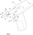
- a powered surgical saw system 20 includes the saw hand piece 22, a pistol-type hand piece 22 being shown, that drives a surgical saw blade 24.
- Other configurations for the hand piece e.g., a pencil-type, may be employed.
- the saw hand piece 22 may include a driving motor (not shown) for operably moving the saw blade, a power source for energizing the driving motor, e.g., a battery or alternating current electrical power from a wall socket, an operator input control element that may be in the form of a finger-responsive trigger 25, and a controller (not shown) for regulating the power supplied to the motor responsive to a displacement of the operator input control element.
- the surgical saw blade 24 is selectively connected to the hand piece 22 by a saw adapter 26 of the hand piece 22.
- the saw adapter 26 may include a blade mount 28 having an interface compatible with an example blade hub 30, 30' of the saw blade 24 of a shape shown in Figures 3 , or alternatively that of Figure 5 .
- the referenced saw adapter 26 may be selectively removable from the rest of the hand piece 22 as illustrated in Figure 2 .
- An example hand piece including such an interface is commercially available as part of the Stryker FI TM Small Bone Power System.
- a saw blade heat sink 32, 32' described in more detail below and illustrated in Figures 8A and 8B , may be incorporated into or joined with the blade mount 28, and may also comprise part of a surgical saw blade thermal management system 70, also described in more detail below.
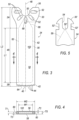
- FIGS. 3 and 4 show the example surgical saw blade 24 in detail.
- the cutting edge 42 may include a plurality of cutting teeth 44.
- a body portion 46 is disposed between and connects the proximal portion 34 and the cutting edge 42 of the distal portion 38.
- a longitudinal axis 48 extends from the proximal end 36 to the distal end 40, substantially bisecting the blade 24.
- the saw blade 24 may be substantially symmetrical about the axis 48, with opposing sides of the blade 24 across the axis 48 being substantially a mirror image of the other.
- the blade 24 and its body portion 46, as shown in Figures 3 and 4 are substantially planar and may be of a substantially constant thickness.
- the blade may include reinforcement features that may be in the form of a surface discontinuity, e.g., a raised rib or ribs.
- An alternative blade for use as a reciprocating saw may have a cutting edge extending on a side of the blade parallel to the longitudinal axis 48.
- the body portion 46 may have a non-planar shape, e.g., a curved shape, with teeth at a distal end, allowing the blade' s use for removal of an artificial acetabular cup.
- the body portion 46 may have a length L1 comprising more than half a length of the saw blade L2.
- An example length L1 may be 24 millimeters ("mm") and an example length L2 may be 36 mm.
- the distal portion 38, and thus the cutting edge 42 and the teeth 44, may all be formed of a first material that has a first yield strength and has a first thermal conductivity.
- the first material may also be a biocompatible material.
- biocompatible means that the so- described material or feature is not toxic or otherwise harmful to human tissue.
- An example biocompatible first material is stainless steel, type 440.
- Subsequent references to steel and to stainless steel and to series 300 and 400 stainless steel are inclusive of stainless steel, type 440.
- a representative range of yield strength of stainless steel is from 450 to 1900 megapascals (MPa).
- a representative range of values of thermal conductivity of stainless steel is 12 to 45 Watts per meter-Kelvin (W/mK).
- the teeth 44 are illustrated as being co-planar with the body portion 46. With the teeth 44 so oriented, the saw blade 24, when held in a planar orientation, cuts a kerf (not shown) having a thickness substantially equal to a saw blade thickness TS of the saw blade 24.
- the thickness TS of the saw blade 24 is illustrated in Figure 4 .
- An example thickness TS is .38 mm.
- the teeth 44 may have tips angled away from a plane of the body, allowing the teeth 44 to cut a kerf having a width greater than the thickness TS of the saw blade 24.
- the proximal portion 34 may be formed of the same material as the distal portion 38 (i.e., the first material).
- One example proximal portion 34 includes the blade hub 30 that includes mounting features, e.g., an engagement arc 50 and a plurality of position-retention slots 52.
- the engagement arc 50 aids in establishing a fore-aft position, i.e., a distal-proximal position of the blade 24 in the blade mount 28.
- the position-retention slots 52 may receive interface elements (not shown) of the blade mount 28 that retain the blade 24 in a rotative position relative to the blade mount 28.
- One alternative blade hub 30' is illustrated in Figure 5 .
- An engagement arc 50' is provided at a bottom of a receiving slot 54.
- Opposed retention slots 52' of feature 30' are engaged by compatible interface elements (not shown).
- the described hubs 30, 30' and their associated mounting features are merely exemplary and not intended to be comprehensive, as many alternatives are well known and in commercial use.
- the proximal portion 34 may share a laminar-type construction used for the body portion 46, such laminar-type construction being described below.
- the body portion 46 includes a thermal transit core 56 formed of a second material, e.g. copper, aluminum, composites, example composite materials including diamond, synthetic diamond and carbon nanotubes, having a second thermal conductivity greater than, and at least twice the first thermal conductivity.
- a thermal transit core 56 formed of a second material, e.g. copper, aluminum, composites, example composite materials including diamond, synthetic diamond and carbon nanotubes, having a second thermal conductivity greater than, and at least twice the first thermal conductivity.
- materials having a high thermal conductivity may have a much lower yield strength than materials well suited to providing the cutting edge 42 and the teeth 44 thereof.
- a representative value of thermal conductivity of copper is 386 W/mK, more than 8 times the above-cited thermal conductivity of stainless steel.
- a representative yield strength of copper, at 70 MPa is much lower than that of stainless steel.
- the body portion 46 may also include a pair of, i.e., two, opposed horizontal flanking members 58 and/or a pair of opposed vertical flanking members 60.
- the flanking members 58, 60 may be made of a stiffer material than the material of the thermal transit core 56, e.g., the same material as the distal portion 38 or the proximal portion 34, such as stainless steel.
- flanking members 58, 60 may aid the transmission of a cutting force from the blade mount 28 to the teeth 44 by providing the body portion 46 with a greater lateral bending stiffness in a cutting mode of operation than would be possible without the flanking members 58, 60.
- the flanking members 58, 60 may extend longitudinally, i.e., extend in the direction of the longitudinal axis 48, from the proximal portion 34 across the body portion 46 to the distal portion 38.
- the labels horizontal and vertical are used consistent with the accompanying drawings only for the convenience of orienting the reader of this description.
- the horizontal flanking members 58 may alternatively be referred to as, for example, the first flanking member, and the vertical flanking members 60 may be referred to as, for example, the second flanking members.
- the core comprises a plurality of surfaces which may include an upper horizontal surface 57, a lower horizontal surface 59, and two vertical surfaces 62.
- One of the horizontal flanking members 58 when incorporated, may be disposed across the upper horizontal surface 57 of the core 56, and another of the horizontal flanking members 58 may be disposed across the lower horizontal surface 59 of the core 56.
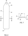
- the upper horizontal surface 57 and the lower horizontal surface 59 of the core 56 each extend longitudinally, consistent with Figures 6 and 7 , an entire length of the core 56.
- the two horizontal surfaces 57, 59 are opposed to each other.
- the upper horizontal surface 57 and the lower horizontal surface 59 as illustrated in Figure 7 are connected with each other on opposed sides by the two oppositely disposed vertical surfaces 62 of the core 56.
- the vertical surfaces 62 also extend longitudinally along the length of the core 56.
- One of the vertical flanking members 60 when incorporated, may be disposed across one of the vertical surfaces 62 of the core 56, and another of the vertical flanking members 60 may be disposed across the opposed vertical surface 62 of the core 56 as shown in Figure 4 .
- the core 56 may be alternatively formed without discreet vertical surfaces 62, by, for example, providing the core with a slightly convex cross section by providing one or both of the horizontal surface 57, 59 with a radius, allowing surfaces 57, 59 to join to each other directly without an intermediate surface.
- flanking members 58 and 60 As with the context of the flanking members 58 and 60, the labels horizontal and vertical, as well as upper and lower, are used consistent with the accompanying drawings only for the convenience of orienting the reader of this description.
- the horizontal surfaces 57 may alternatively be referred to as the first surfaces, and the vertical surfaces 62 may be referred to as the second surfaces.
- a width W1 of the core 56 as shown in Figure 7 may be equal to a full width W2 of the saw blade 24 and the width W2 of the opposed horizontal flanking members 58. Or, as may be seen in Figure 4 , a width W1 of the core 56 may be less than a width W2 of the saw blade 24 and the horizontal flanking members 58 to accommodate the inclusion of the vertical flanking members 60 against the vertical surfaces 62.
- An example width W1 may be 7 mm and an example width W2 may be 9 mm.
- the width W2 may be greater than the width W1 to allow the vertical flanking members 60 to be disposed against each of the opposed vertical surfaces 62.
- a distal edge 64 of the core 56 is engaged by the distal portion 38 of the blade 24.
- a proximal end 66 of the core 56 may extend into the blade hub 30 to aid in a transfer of heat from the teeth 44 as described in more detail below.
- the thermal transit core 56 is illustrated in Figure 6 as including a positioning slot 68 employed in association with the illustrated blade hub 30.
- the core 56 may be formed without the positioning slot 68, and may have the slot 68 formed as part of the saw blade's assembly operation as described in more detail below.
- use of the blade hub 30' shown in Figure 5 would not require the provision of one of the positioning slots 68 in the core 56.
- the vertical flanking members 60 and inner parts of the proximal portion 34 and the distal portion 38 may be formed as an integral unit, as described in greater detail below.
- the body portion 46 may be provided with a biocompatible surface.
- a layer forming the biocompatible surface may be provided by disposing the flanking members 58, 60 over the upper horizontal surface 57, over the lower horizonal surface 59 and over the vertical surfaces 62 of the core 56.
- the biocompatible surface may alternatively be provided by alternative types of layers, e.g., integrally formed layers and coatings as illustrated in Figure 15 and described below.
- the layer 72' may be integral with the thermal transit core 56.
- the biocompatible surface layer may be a layer of aluminum oxide, or an anodized aluminum layer.
- the layer 72' of biocompatible material may be provided with other materials and coating methods, e.g., deposition of polymeric coatings, electro-plating of biocompatible metals, e.g., gold, deposition of titanium nitride.
- the surgical saw blade 24 may comprise part of the thermal management system 70.
- the thermal management system 70 may include the supplemental heat sink 32, 32' disposed over and integrated into the blade mount 28 as illustrated in Figures 8A and 8B .
- the heat sink 32, 32' is identified as a supplemental heat sink 32, 32', as the blade mount 28 may have an inherent capacity to act as a heat sink.
- the heat sink 32, 32' may be a passive heat sink 32 or an active heat sink 32'.
- the heat sink 32, 32' is connected to the surgical saw blade 24 through the blade hub 30 of the blade 24 and the blade mount 28. Alternatively, the heat sink 32, 32' may be connected to the blade 24 by an intermediate heat transport path, not shown.
- the thermal management system 70 comprise the heat sink 32, 32' and may be independent of the blade 24 and the blade type, and may be used with a conventional saw blade with beneficial effect.
- FIG 8A shows an example passive heat sink 32 with a plurality of cooling fins 74 extending from a heat sink base 76. Heat is transferred from the blade 24 to the base 76 of the heat sink 32. Heat radiates from the fins 74 into the surrounding air.
- the heat sink 32 is identified as "passive" as it requires no supplemental power to perform is function of absorbing and dissipating heat energy.
- FIG 8B shows an example active heat sink 32' as might be provided with an electrically actuable active heat sink, e.g., a Peltier cooler 32'.
- the active heat sink 32' may be disposed over the blade mount 28.
- a plurality of wires 78 may be used to connect the active heat sink to an electronic controller 80 for power, and to communicate a feedback signal from a temperature sensor (not shown) at the blade mount 28 to the controller 80.
- Power from an electrical power source 82 e.g., a battery, may be communicated by the controller 80 to the Peltier cooler 32' or other active heat sink.
- the controller 80 and the power source 82 may be the same as the controller and power source incorporated into the hand piece 22. Although not illustrated, such communication of power and signals may be done wirelessly.
- the heat sink 32' is identified as "active” as it employs supplemental power, e.g., electrical power, to perform is function of absorbing and dissipating heat energy.
- An alternative active heat dissipation mechanism may supplement the otherwise passive heat sink 32 with a fan (not shown) positioned to blow air across the fins 74.
- the fan may be electrically responsive to an electronic controller.
- One example method including a plurality of steps to fabricate the saw blade 24 is described below and illustrated in Figures 9 through 12C .
- a sufficiently strong material e.g., series 300 or 400 stainless steel, tungsten carbide, or titanium, is identified and selected for use as the first material for use in forming the distal portion 38, and thus the cutting edge 42 and the teeth 44, and the flanking members 58, 60.
- the first material may also be a biocompatible material.
- thermally conductive material having a significantly higher thermal conductivity than the first material is identified and selected for use as the second material for the thermal transit cores 56.
- Suitable materials for the thermal transit cores 56 include but are not limited to copper and aluminum.
- Copper as used herein includes pure copper and copper-based alloys.
- aluminum as used herein includes pure aluminum and aluminum-based alloys.
- Alternative thermally conductive materials may include other materials, compounds, composites and laminates.
- the second material may include alternating layers of aluminum and copper, or yet alternatively may include a fine mesh grid of steel with copper filling the voids in the mesh disposed between the cutting edge 42 and the proximal portion 34. Such example are illustrative and not intended to be comprehensive.
- One example method of making the saw blades 24, illustrated in Figures 9 through 12C includes the step of forming a laminate in the form of a blade blank sheet assembly 96 including the first material and the second material, with a first layer 92, and a second layer 90, and an intermediate layer disposed in-between.
- the first layer 92 in the form of a substantially planar first sheet 92 of the first material having an example thickness T2 of .08 mm is provided.
- the first sheet 92 has a first planar area A1 that may depend on the available manufacturing equipment suitable for forming and processing the blank sheet assembly 96.
- the second layer 90 in the form of, i.e., comprises, a substantially planar second sheet 90 of the first material, also having an example thickness T2 of .08 mm is provided.
- the second sheet 90 has a second planar area substantially equal to the first planar area A1.
- the intermediate layer may include both the first material, e.g., stainless steel, for incorporation therein, and the second material, e.g., copper, for incorporation therein.
- the first material for the intermediate layer may be provided as a third sheet 84 of the first material that may be of the first planar area A1.
- the intermediate layer may also include a plurality of cores 56 formed of the second material.
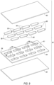
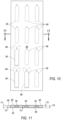
- the first planar area A1 of the third sheet 84 is sufficiently large to accommodate a fabrication of a predetermined number of saw blades 24, with twelve saw blades 24 being an example number illustrated in Figures 9 and 10 .
- a plurality of pockets 86, one for each of the blades 24 to be formed, are formed in the third sheet 84 in anticipation of receiving thermal transit cores 56 therein.
- the example pockets 86 are of a predetermined size, complementary in size and shape to the thermal transit cores 56, with the pockets 86 being of substantially the same size and shape as the cores 56. Accordingly, the cores 56 are of substantially the same size and shape as the pockets 86.
- the third sheet 84 may have a thickness of .23 mm.
- the orientation of the pockets 86 may be such that the utilization of the sheet 84 to produce blades 24 is maximized. Complete or perfect utilization would be 100%, with no waste of the third sheet 84.
- the pockets 86 may be formed by stamping, by die cutting, by laser cutting and by any alternative suitable forming method.
- the pockets 86 may, but need not, extend completely through the third sheet 84.
- the pockets 86 of the present example do extend completely through the third sheet 84, in part because the example third sheet 84 is substantially the same thickness TI as the example cores 56.
- the thermally conductive second material is formed into a plurality of the thermal transit cores 56.
- Figures 9 and 10 show twelve thermal transit cores 56 for the purpose of illustrating the concepts described herein, but this number can be varied to suit the manufacturing methods and equipment and the capabilities of such.
- One method of forming the cores 56 is to cut them from a sheet of thermally conductive material.
- a sheet (not shown) of thermally conductive material chosen as thermal transit core material, e.g., copper, aluminum, having an example thickness T1 of .23 mm, is provided.
- the cores 56 may be cut from the sheet into a desired shape and size. An example shape is shown in Figure 6 , with thickness T1 shown in the sectional view of Figure 7 .
- Cutting cores 56 from the sheet may be achieved by any commercially practicable method, with example methods including die cutting and laser cutting.
- the thermal transit cores 56 may be placed into the pockets 86 of the third sheet 84.
- the relative sizes of the pockets 86 and the cores 56 may be selected to provide a press fit of the cores 56 into the pockets 86, or a slip fit to allow easy placement of the cores 56 within the pockets 86.
- the use of a slip fit may be better suited to use in arrangements in which the pockets 86 do not extend entirely through the third sheet 84, or in which the first sheet 92 of stainless steel, i.e., a stainless steel sheet 92, is fixed to a first surface 94 of the third sheet 84 prior to insertion of the cores 56, with the first sheet 92 defining a bottom to the pockets 86.
- the first substantially planar sheet 92 is placed over a first surface 94 of the third sheet 84, in alignment therewith and is fixed to the third sheet 84.
- the third sheet 84 and the first sheet 92 may be connected by fixing, e.g., welding, adhesively bonding, the sheets 84, 92 together.
- the second substantially planar sheet 90 is placed over a second surface 88 of the third sheet 84, the second surface 88 being opposite the first surface 94, in alignment therewith and is fixed to the third sheet 84.
- the third sheet 84 and the second sheet 90 may be connected by fixing, e.g., welding, adhesively bonding the sheets 84, 90 together.
- the vertical flanking members 60 comprise part of the third sheet 84, connecting what will become inner parts of the proximal portion 34 and the distal portion 38 that are also comprised by part of the third sheet 84.
- the vertical flanking members 60 and the portions of the proximal portion 34 and the distal portion 38 formed of the third sheet 84 are formed as an integral unit.
- Sheets 90 and 92 provide example horizontal flanking members 58 over the cores 56 in the finished saw blades 24.
- the horizontal flanking members 58 provided by the sheets 90 and 92 may additionally beneficially aid in the retention of the core 56 in the pocket 86 of the finished blade 24 during use of the blade 24.
- the pockets 86 in the third sheet 84 do not extend completely through the third sheet 84. After the cores 56 have been disposed in the pockets 86, the cores 56 are retained therein by fixing the second sheet 90 over the third sheet 84 as described above. With the cores 56 so retained, there is no need for the first sheet 92.
- the first and third sheets 92, 84 may be of equal thickness, e.g., .19 mm, with each having pockets 86 formed therein with a depth of each pocket 86 being of a depth substantially equal to one half the thickness TI of the cores 56, e.g., .11 mm.
- the sheets 92, 84 are fixed together.
- the cores 56 are disposed in the pockets 86 of one of the sheets 92, 84.
- the second sheet 90 is then aligned with and lowered over and onto the third sheet 84.
- the sheets 84, 90 are then fixed to each other.
- the assembled cores 56 and sheets 84, 90, 92 comprise the blank sheet assembly 96.
- a plurality of saw blade blanks 98, twelve in the illustrated example, may be cut from the blank sheet assembly 96. Profiles of the blade blanks 98 are shown on the blank sheet assembly 96 in phantom.
- a blade blank 98 is shown in Figure 12A , substantially as it would appear after being cut from the sheet assembly 96.
- the blade blank 98 may be further processed as indicated in Figures 12B and 12C to produce a completed blade 24.
- the blank 98 may have position-retention slots 52 formed by die cutting or other suitable material removal method to provide the partially finished blanks 98 of Figure 12B . Such material removal may alternatively be performed when the blade blanks 98 are still part of the blank sheet assembly 96.
- the teeth 44 may be formed by cutting the edge 42.
- the teeth 44 may be ground and finish-ground to achieve their final shape and surface finish illustrated in Figures 12C and 3 .
- the engagement arc 50 may be completely formed by the process in which the blade blank 98 is cut from the blank sheet assembly 96.
- the engagement arc 50 may alternatively be formed or formed in part by machining or grinding after the blade blank 98 is cut from the blank sheet assembly 96.
- the intermediate layer including the first material and the second material, may be provided by an alternating plurality of parallel strips, i.e., ribbons, of the first material and the second material.
- Strips of the first material may be of a first width, substantially equal to at least a length of the distal portion 38 to accommodate forming blanks 98 having the distal portion 38 formed entirely of the first material.
- the strips of the first material may be wider, e.g., as wide as at least a combined length of the proximal portion and the distal portion, to accommodate forming blanks 98 having both proximal portions 34 and distal portions 38 formed substantially entirely of the first material.
- Strips of the second material may be of a second width substantially equal to a length of the proximal portion 34 and the body portion 46.
- the strips of the first material may be fixed, e.g., welded, adhesively bonded, to the opposing first and second sheets 92, 90.
- Blade blanks 98 are then cut from the assembled blank sheet assembly, with the sheets 92, 90 forming the horizontal flanking members 58. The blanks 98 are then processed into blades 24 in accord with the above.
- An alternative method of forming the blades 24 may include the use of additive manufacturing methods, i.e., 3D printing.
- the blade 24 in its entirety by additive manufacturing.
- a blade blank 98 may be formed in its entirety by additive manufacturing and then finish machined.
- components of the blade blank, e.g., the core 56 may be formed by additive manufacturing and then incorporated into the blank sheet assembly 96.
- the components of the blade blank, e.g., the core 56, the flanking members 58, 62, the distal portion 38 and the proximal portion 34 may be formed separately or in combination and subsequently assembled.
- the completed blade 24 has its blade hub 30 inserted into, i.e., received by, and engaged by the blade mount 28.
- the blade 24 may be pivoted about an axis 100 of the mount 28.
- the axis 100 is substantially normal to a substantially planar surface 102 of the blade 24.
- the teeth 44 may be directed against a surgical site surface, e.g., a bone surface.
- the motion of the blade 24 relative to the surgical site surface and relative to the hand piece 22 causes the teeth 44 to sweep back and forth in a plane and across the bone, removing bone material from the bone, while cutting a slot with a kerf of a width substantially equal to the blade thickness TS.
- the energy from a motor (not shown) in the hand piece 22 is, in large part, transferred to the teeth 44 to cut the bone.
- Heat generated at a cutting site, where the teeth 44 are removing bone, is conducted by the blade 24 away from the teeth 44 and toward the mount 28.
- the rate of heat conduction through the core 56 is greater and more rapid than the rate through steel, allowing the saw blade 24 with its thermal transit core 56 to operate at a lower temperature than a conventional steel blade.
- the transfer of heat away from the teeth 44 through the blade 24 is facilitated by heat transfer mechanisms including conduction through the core, radiation and convection. Heat is lost by the blade 24 and the core 56 across the length LI of the blade's thermal transit core 56 to the surrounding air by both convection and radiation, in combination with conduction.
- the core 56 conducts heat along the length L2 of the blade, with some of the heat being conducted through the comparatively thin layer of steel defining the horizontal flanking member 58 to the surface 102 of the blade to the surrounding environment, e.g., air. Heat passing though the layer of steel 58 to the outer surface 102 of the blade will be dissipated by radiation, and by convection as air moves across the outer surface 102 of the blade.
- Heat is also conducted through the core 56 to the mount 28. Conduction of heat through the blade 24 away from the teeth may be further facilitated by providing the heat sink 32, 32' at the mount 28. Removal of heat from the heat sink 32, 32' enhances removal of heat from the blade 24 and from the cutting site.
- FIGS 13 through 16 show example alternative surgical saw blades 24' and 24".
- Like reference numbers e.g. 24 and 24' and 24" identify like parts and features, subject to the described distinctions.
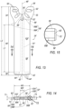
- FIGs 13, 14 and 15 show the example alternative example surgical saw blade 24' in greater detail.
- the saw blade 24' is much like the blade 24, except that the saw blade 24' includes a longitudinal beam 6G and does not include flanking members 60.
- a proximal portion 34' of the blade 24' disposed at a proximal end 36' of the blade 24', includes a blade hub, e.g., blade hub 30 or blade hub 30'.
- a distal portion 38' of the blade 24' disposed at a distal end 40' of the blade 24', includes the cutting edge 42'.
- the cutting edge 42' may include the cutting teeth 44'.
- a body portion 46' is disposed between and connects the proximal portion 34' and the cutting edge 42' of the distal portion 38'.
- the longitudinal axis 48 extends from the proximal end 36' to the distal end 40', substantially bisecting the blade 24'.
- the saw blade 24' may be substantially symmetrical about the axis 48, with opposing sides of the blade 24' across the axis 48 being substantially a mirror image of the other.
- the blade 24' and its body portion 46', as shown in Figures 13 and 14 are substantially planar.
- the body portion 46' of the blade 24' may have a length L1' comprising more than half a length of the saw blade L2'.
- the distal portion 38', and thus the cutting edge 42' and the teeth 44' of blade 24' may be formed of the above-described first material.
- the proximal portion 34' may be formed of the same material as the distal portion 38', i.e., the first material.
- the illustrated proximal portion 34' is substantially the same as the proximal portion 34, and includes a blade hub 30 that includes an engagement arc 50' and a plurality of position-retention slots 52'.
- the configuration of the blade hub is exemplary.
- the body portion 46' includes a thermal transit core 56' that may be formed of the above-described second material, e.g. copper, aluminum, composites, having a second thermal conductivity greater than the first thermal conductivity.
- the thermal transit core 56' may be substantially bisected into a first half 56A' and a second half 56B' by the longitudinal beam 61'.
- the longitudinal beam 61' may be formed of the same material as the distal portion 38'.
- the longitudinal beam 61' may extend between and connect the proximal portion 34' and the distal portion 38'.
- the longitudinal beam 61' may further be of an example third width W3' substantially narrower than the width W2 of the blade.
- the width W2 may be 9 mm as described above.
- An example width W3' may be 2 mm.
- the body portion 46' may also include a pair of opposed of horizontal flanking members 58'.
- the flanking members 58' may extend longitudinally, i.e., extend in the direction of the longitudinal axis 48, from the proximal portion 34' across the body portion 46' to the distal portion 38', or may alternatively be disposed over and comprise part of each of the proximal portion 34' and the distal portion 38'.
- One of the horizontal flanking members 58' may be disposed across an upper horizontal surface 57', comprising surfaces 57A' and 57B' of the core halves 56A' and 56B' respectively, and over the beam 61'.
- the opposed horizontal flanking members 58' may be disposed across a lower horizontal surface 59' of the core 56', the lower horizontal surface 59' comprising surfaces 59A' and 59B' of the core halves 56A' and 56B' respectively, and over the beam 61'.
- the upper horizontal surface 57' and the lower horizontal surface 59' of the core 56' each extend longitudinally an entire length of the core 56'.
- the upper horizontal surface 57' and the lower horizontal surface 59' as illustrated in Figure 7 are connected with each other on opposed sides by two oppositely disposed vertical surfaces 62' of the core 56'.
- the vertical surfaces 62' also extend longitudinally along the length of the core 56' and may be exposed, permitting contact therewith.
- the beam 6G and inner parts of the proximal portion 34 and the distal portion 38 may be formed as a single integral piece.
- the body portion 46' may be provided with a biocompatible surface.
- the layer forming the biocompatible surface may be provided by disposing the horizontal flanking members 58' over the upper horizontal surface 57', and over the lower horizontal surface 59'.
- a thin surface layer 72' of biocompatible material e.g., aluminum oxide, anodized aluminum, polymeric coatings, gold, titanium nitride, may be applied.
- Such a surface layer 72' when so formed may be relatively thin (e.g., .01 mm), and thus may not substantially impact the ultimate width W2 of the blade 24'.
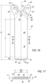
- FIGs 16 and 17 show the example alternative surgical saw blade 24" in greater detail.
- the saw blade 24" is much like the blade 24, except that the width W1" of the core 56" is equal to the full width W2" of the saw blade 24" and the width W2" of the opposed horizontal flanking members 58.
- Vertical flanking members 60 are not employed in the saw blade 24".
- An example width W1" may be 9 mm and an example width W2" may be 9 mm.
- a distal edge 64 of the core 56" is engaged by the distal portion 38 of the blade 24".
- a proximal end 66" of the core 56" may extend into the blade hub 30" to aid in a transfer of heat from the teeth 44 as described above.
- Vertical surfaces 62" may be provided with a layer 72' to provide a biocompatible surface 72' as described above and as shown in Figure 15 .
- a surgical saw blade, a blade thermal management system and a method for making the surgical saw blade have all been disclosed.
- the disclosed blade facilitates an improved surgical saw system facilitating improved surgical efficiency in that for a given tooth pitch and profile, cutting may be done at a higher rate of speed for a predetermined temperature at the cutting site, and improved precision in that a blade with a finer tooth pitch may be used to cut at the same rate of speed as a less precise blade having a coarser tooth pitch while not exceeding the predetermined temperature.
- the adverb "substantially" means that a shape, structure, measurement, quantity, time, etc. may deviate from an exact described geometry, distance, measurement, quantity, time, etc., because of imperfections in materials, machining, manufacturing, transmission of data, computational speed, etc.
Landscapes
- Health & Medical Sciences (AREA)
- Surgery (AREA)
- Life Sciences & Earth Sciences (AREA)
- Engineering & Computer Science (AREA)
- Heart & Thoracic Surgery (AREA)
- Nuclear Medicine, Radiotherapy & Molecular Imaging (AREA)
- Oral & Maxillofacial Surgery (AREA)
- Biomedical Technology (AREA)
- Dentistry (AREA)
- Medical Informatics (AREA)
- Molecular Biology (AREA)
- Animal Behavior & Ethology (AREA)
- General Health & Medical Sciences (AREA)
- Public Health (AREA)
- Veterinary Medicine (AREA)
- Mechanical Engineering (AREA)
- Surgical Instruments (AREA)
Priority Applications (1)
| Application Number | Priority Date | Filing Date | Title |
|---|---|---|---|
| EP25210044.1A EP4706556A1 (de) | 2018-07-27 | 2019-07-24 | Chirurgisches sägeblatt und wärmeverwaltungssystem |
Applications Claiming Priority (4)
| Application Number | Priority Date | Filing Date | Title |
|---|---|---|---|
| US201862703944P | 2018-07-27 | 2018-07-27 | |
| EP22178974.6A EP4079235B1 (de) | 2018-07-27 | 2019-07-24 | Chirurgische sägessystem |
| PCT/US2019/043284 WO2020023664A1 (en) | 2018-07-27 | 2019-07-24 | Surgical saw blade and thermal management system |
| EP19749994.0A EP3829460B1 (de) | 2018-07-27 | 2019-07-24 | Klinge für chirurgische säge |
Related Parent Applications (2)
| Application Number | Title | Priority Date | Filing Date |
|---|---|---|---|
| EP19749994.0A Division EP3829460B1 (de) | 2018-07-27 | 2019-07-24 | Klinge für chirurgische säge |
| EP22178974.6A Division EP4079235B1 (de) | 2018-07-27 | 2019-07-24 | Chirurgische sägessystem |
Related Child Applications (1)
| Application Number | Title | Priority Date | Filing Date |
|---|---|---|---|
| EP25210044.1A Division EP4706556A1 (de) | 2018-07-27 | 2019-07-24 | Chirurgisches sägeblatt und wärmeverwaltungssystem |
Publications (3)
| Publication Number | Publication Date |
|---|---|
| EP4299017A2 true EP4299017A2 (de) | 2024-01-03 |
| EP4299017A3 EP4299017A3 (de) | 2024-03-06 |
| EP4299017B1 EP4299017B1 (de) | 2025-10-22 |
Family
ID=67544443
Family Applications (4)
| Application Number | Title | Priority Date | Filing Date |
|---|---|---|---|
| EP19749994.0A Active EP3829460B1 (de) | 2018-07-27 | 2019-07-24 | Klinge für chirurgische säge |
| EP25210044.1A Pending EP4706556A1 (de) | 2018-07-27 | 2019-07-24 | Chirurgisches sägeblatt und wärmeverwaltungssystem |
| EP23209624.8A Active EP4299017B1 (de) | 2018-07-27 | 2019-07-24 | Chirurgisches sägeblatt und verfahren zur herstellung eines chirurgischen sägeblatts |
| EP22178974.6A Active EP4079235B1 (de) | 2018-07-27 | 2019-07-24 | Chirurgische sägessystem |
Family Applications Before (2)
| Application Number | Title | Priority Date | Filing Date |
|---|---|---|---|
| EP19749994.0A Active EP3829460B1 (de) | 2018-07-27 | 2019-07-24 | Klinge für chirurgische säge |
| EP25210044.1A Pending EP4706556A1 (de) | 2018-07-27 | 2019-07-24 | Chirurgisches sägeblatt und wärmeverwaltungssystem |
Family Applications After (1)
| Application Number | Title | Priority Date | Filing Date |
|---|---|---|---|
| EP22178974.6A Active EP4079235B1 (de) | 2018-07-27 | 2019-07-24 | Chirurgische sägessystem |
Country Status (7)
| Country | Link |
|---|---|
| US (2) | US12162085B2 (de) |
| EP (4) | EP3829460B1 (de) |
| JP (2) | JP7382391B2 (de) |
| CN (1) | CN112423681B (de) |
| AU (2) | AU2019309379B2 (de) |
| CA (1) | CA3107786A1 (de) |
| WO (1) | WO2020023664A1 (de) |
Families Citing this family (4)
| Publication number | Priority date | Publication date | Assignee | Title |
|---|---|---|---|---|
| EP3829460B1 (de) * | 2018-07-27 | 2022-06-15 | Stryker Corporation | Klinge für chirurgische säge |
| IT202100020174A1 (it) * | 2021-07-28 | 2023-01-28 | Attilio Cavagna | Unità di taglio per settori industriali provvisto di motore torque |
| US11864774B2 (en) | 2021-09-09 | 2024-01-09 | Arthrex, Inc. | Adapter assembly for surgical cutting tool |
| CN115227332B (zh) * | 2022-06-30 | 2024-11-05 | 重庆西山科技股份有限公司 | 具有冷却系统的护鞘锯片 |
Family Cites Families (27)
| Publication number | Priority date | Publication date | Assignee | Title |
|---|---|---|---|---|
| US3681846A (en) | 1970-02-09 | 1972-08-08 | Gerber Garment Technology Inc | Knife blade construction |
| JPS5853970B2 (ja) | 1981-12-19 | 1983-12-02 | 卯一 宮脇 | 畔挽鋸の鋸刃版製造方法 |
| US4770067A (en) | 1987-06-08 | 1988-09-13 | Kollmorgen Corporation | Method of manufacturing surgical cutting tools for thermally aided surgery |
| US5002555A (en) * | 1989-02-10 | 1991-03-26 | Petersen Thomas D | Gall-resistant ribbed surgical saw blade |
| US5122142A (en) | 1990-09-13 | 1992-06-16 | Hall Surgical Division Of Zimmer, Inc. | Irrigating saw blade |
| US6022353A (en) * | 1991-05-30 | 2000-02-08 | Synasive Technology, Inc. | Surgical saw blade |
| US7527628B2 (en) | 1991-05-30 | 2009-05-05 | Synvasive Technology, Inc. | Surgical saw blade having at least one pair of opposed teeth shaped as right triangles |
| US5308311A (en) | 1992-05-01 | 1994-05-03 | Robert F. Shaw | Electrically heated surgical blade and methods of making |
| JPH1156867A (ja) | 1997-08-12 | 1999-03-02 | Yasuto Takeuchi | 超音波手術装置 |
| US6656186B2 (en) * | 2002-04-22 | 2003-12-02 | Molecular Metallurgy, Inc. | Bone saw blade and a method for manufacturing a bone saw blade |
| JP2004001134A (ja) | 2002-05-31 | 2004-01-08 | Hitachi Koki Co Ltd | 切断用ブレード |
| US20040243136A1 (en) * | 2003-05-30 | 2004-12-02 | Parag Gupta | Dual cut surgical saw blade |
| US7473265B2 (en) | 2004-03-15 | 2009-01-06 | Boston Scientific Scimed, Inc. | Filter media and methods of manufacture |
| US20060016315A1 (en) | 2004-07-23 | 2006-01-26 | Zorich Timothy A | Saw cutting blade |
| US20060195106A1 (en) | 2005-02-02 | 2006-08-31 | Jones Bryan S | Ultrasonic cutting device |
| US8157619B2 (en) | 2005-06-27 | 2012-04-17 | Husqvarna Professional Outdoor Products Inc. | Tools and methods for making and using tools, blades and methods of making and using blades |
| US20080234709A1 (en) | 2007-03-22 | 2008-09-25 | Houser Kevin L | Ultrasonic surgical instrument and cartilage and bone shaping blades therefor |
| US8142425B2 (en) * | 2007-10-30 | 2012-03-27 | Hemostatix Medical Techs, LLC | Hemostatic surgical blade, system and method of blade manufacture |
| US8920424B2 (en) | 2008-06-11 | 2014-12-30 | Medtronic Ps Medical, Inc. | Micro-saw blade for bone-cutting surgical saws |
| US8157151B2 (en) | 2009-10-15 | 2012-04-17 | Tyco Healthcare Group Lp | Staple line reinforcement for anvil and cartridge |
| DE202010004990U1 (de) | 2010-04-14 | 2010-08-12 | Mahe Medical Gmbh | Chirurgisches Sägeblatt |
| DE102010014917B4 (de) | 2010-04-14 | 2014-01-16 | Mahe Medical Gmbh | Chirurgisches Sägeblatt |
| JP6540986B2 (ja) | 2015-01-26 | 2019-07-10 | 株式会社デンソー | 回転電機 |
| US10543000B2 (en) | 2015-07-02 | 2020-01-28 | AOD Holdings, LLC | Reciprocating surgical saw blade |
| US10702283B2 (en) | 2016-11-10 | 2020-07-07 | Biomedtrix, Llc | Radial saw blade and hub for osteotomy |
| US11389987B2 (en) * | 2018-06-29 | 2022-07-19 | Synthes Gmbh | Hybrid saw blade |
| EP3829460B1 (de) * | 2018-07-27 | 2022-06-15 | Stryker Corporation | Klinge für chirurgische säge |
-
2019
- 2019-07-24 EP EP19749994.0A patent/EP3829460B1/de active Active
- 2019-07-24 EP EP25210044.1A patent/EP4706556A1/de active Pending
- 2019-07-24 CA CA3107786A patent/CA3107786A1/en active Pending
- 2019-07-24 EP EP23209624.8A patent/EP4299017B1/de active Active
- 2019-07-24 WO PCT/US2019/043284 patent/WO2020023664A1/en not_active Ceased
- 2019-07-24 JP JP2021504524A patent/JP7382391B2/ja active Active
- 2019-07-24 US US17/260,305 patent/US12162085B2/en active Active
- 2019-07-24 EP EP22178974.6A patent/EP4079235B1/de active Active
- 2019-07-24 AU AU2019309379A patent/AU2019309379B2/en active Active
- 2019-07-24 CN CN201980046936.9A patent/CN112423681B/zh active Active
-
2023
- 2023-11-06 JP JP2023189453A patent/JP7856622B2/ja active Active
-
2024
- 2024-11-23 US US18/957,663 patent/US20250083240A1/en active Pending
-
2025
- 2025-02-21 AU AU2025201224A patent/AU2025201224A1/en active Pending
Also Published As
| Publication number | Publication date |
|---|---|
| EP4706556A1 (de) | 2026-03-11 |
| JP2024020306A (ja) | 2024-02-14 |
| EP3829460A1 (de) | 2021-06-09 |
| CN112423681A (zh) | 2021-02-26 |
| CA3107786A1 (en) | 2020-01-30 |
| EP4299017B1 (de) | 2025-10-22 |
| EP4079235A1 (de) | 2022-10-26 |
| AU2025201224A1 (en) | 2025-03-13 |
| US20220009013A1 (en) | 2022-01-13 |
| AU2019309379A1 (en) | 2021-01-28 |
| CN112423681B (zh) | 2024-08-27 |
| JP2021532862A (ja) | 2021-12-02 |
| EP3829460B1 (de) | 2022-06-15 |
| JP7856622B2 (ja) | 2026-05-11 |
| US20250083240A1 (en) | 2025-03-13 |
| AU2019309379B2 (en) | 2024-11-21 |
| JP7382391B2 (ja) | 2023-11-16 |
| EP4299017A3 (de) | 2024-03-06 |
| US12162085B2 (en) | 2024-12-10 |
| WO2020023664A1 (en) | 2020-01-30 |
| EP4079235B1 (de) | 2023-11-22 |
Similar Documents
| Publication | Publication Date | Title |
|---|---|---|
| US20250083240A1 (en) | Surgical Saw Blade and Thermal Management System | |
| EP3771440B1 (de) | Ultraschall-knochenskalpellbohrer und robotergestütztes ultraschall-antriebssystem für denselben | |
| CN104244847B (zh) | 医用铰刀及形成医用铰刀的方法 | |
| US20200001494A1 (en) | Hybrid saw blade | |
| US8394116B2 (en) | Surgical tools and components thereof | |
| US20130204254A1 (en) | Limited Use Acetabular Reamer | |
| JP2013521140A (ja) | 正面フライスおよびその使用 | |
| US20220387049A1 (en) | Medical devices and related methods for transforming bone, other tissue, or material | |
| US20100329805A1 (en) | Diamond tool | |
| WO2021152498A1 (en) | Spheroidal surgical rasp | |
| JP7828355B2 (ja) | 外科用切削工具 | |
| CN210811334U (zh) | 超声骨刀刀头及使用该刀头的机器人辅助超声骨动力系统 | |
| CN223380612U (zh) | 一种医用摆锯 | |
| EP4591806A1 (de) | Orthopeadischer fräser | |
| JPWO2018159173A1 (ja) | ブレード、ブレードを備えたセーバソー、および、ブレードの製造方法 | |
| EP4691381A1 (de) | Träger und handhabungsrahmen für teile zur generativen fertigung | |
| CN207479709U (zh) | 一种改变切削力的主缸槽刀 |
Legal Events
| Date | Code | Title | Description |
|---|---|---|---|
| PUAI | Public reference made under article 153(3) epc to a published international application that has entered the european phase |
Free format text: ORIGINAL CODE: 0009012 |
|
| STAA | Information on the status of an ep patent application or granted ep patent |
Free format text: STATUS: THE APPLICATION HAS BEEN PUBLISHED |
|
| AC | Divisional application: reference to earlier application |
Ref document number: 4079235 Country of ref document: EP Kind code of ref document: P Ref document number: 3829460 Country of ref document: EP Kind code of ref document: P |
|
| AK | Designated contracting states |
Kind code of ref document: A2 Designated state(s): AL AT BE BG CH CY CZ DE DK EE ES FI FR GB GR HR HU IE IS IT LI LT LU LV MC MK MT NL NO PL PT RO RS SE SI SK SM TR |
|
| REG | Reference to a national code |
Ref country code: DE Ref legal event code: R079 Free format text: PREVIOUS MAIN CLASS: A61B0017000000 Ipc: A61B0017140000 Ref document number: 602019077310 Country of ref document: DE |
|
| PUAL | Search report despatched |
Free format text: ORIGINAL CODE: 0009013 |
|
| AK | Designated contracting states |
Kind code of ref document: A3 Designated state(s): AL AT BE BG CH CY CZ DE DK EE ES FI FR GB GR HR HU IE IS IT LI LT LU LV MC MK MT NL NO PL PT RO RS SE SI SK SM TR |
|
| RIC1 | Information provided on ipc code assigned before grant |
Ipc: A61B 17/00 20060101ALN20240131BHEP Ipc: A61B 17/14 20060101AFI20240131BHEP |
|
| STAA | Information on the status of an ep patent application or granted ep patent |
Free format text: STATUS: REQUEST FOR EXAMINATION WAS MADE |
|
| 17P | Request for examination filed |
Effective date: 20240904 |
|
| RBV | Designated contracting states (corrected) |
Designated state(s): AL AT BE BG CH CY CZ DE DK EE ES FI FR GB GR HR HU IE IS IT LI LT LU LV MC MK MT NL NO PL PT RO RS SE SI SK SM TR |
|
| RAP3 | Party data changed (applicant data changed or rights of an application transferred) |
Owner name: STRYKER CORPORATION |
|
| GRAP | Despatch of communication of intention to grant a patent |
Free format text: ORIGINAL CODE: EPIDOSNIGR1 |
|
| STAA | Information on the status of an ep patent application or granted ep patent |
Free format text: STATUS: GRANT OF PATENT IS INTENDED |
|
| RIC1 | Information provided on ipc code assigned before grant |
Ipc: A61B 17/00 20060101ALN20250411BHEP Ipc: A61B 17/14 20060101AFI20250411BHEP |
|
| RIC1 | Information provided on ipc code assigned before grant |
Ipc: A61B 17/00 20060101ALN20250427BHEP Ipc: A61B 17/14 20060101AFI20250427BHEP |
|
| INTG | Intention to grant announced |
Effective date: 20250513 |
|
| GRAS | Grant fee paid |
Free format text: ORIGINAL CODE: EPIDOSNIGR3 |
|
| GRAA | (expected) grant |
Free format text: ORIGINAL CODE: 0009210 |
|
| STAA | Information on the status of an ep patent application or granted ep patent |
Free format text: STATUS: THE PATENT HAS BEEN GRANTED |
|
| P01 | Opt-out of the competence of the unified patent court (upc) registered |
Free format text: CASE NUMBER: UPC_APP_6508_4299017/2025 Effective date: 20250910 |
|
| AC | Divisional application: reference to earlier application |
Ref document number: 4079235 Country of ref document: EP Kind code of ref document: P Ref document number: 3829460 Country of ref document: EP Kind code of ref document: P |
|
| AK | Designated contracting states |
Kind code of ref document: B1 Designated state(s): AL AT BE BG CH CY CZ DE DK EE ES FI FR GB GR HR HU IE IS IT LI LT LU LV MC MK MT NL NO PL PT RO RS SE SI SK SM TR |
|
| REG | Reference to a national code |
Ref country code: CH Ref legal event code: F10 Free format text: ST27 STATUS EVENT CODE: U-0-0-F10-F00 (AS PROVIDED BY THE NATIONAL OFFICE) Effective date: 20251022 Ref country code: GB Ref legal event code: FG4D |
|
| REG | Reference to a national code |
Ref country code: DE Ref legal event code: R096 Ref document number: 602019077310 Country of ref document: DE |
|
| REG | Reference to a national code |
Ref country code: IE Ref legal event code: FG4D |
|
| REG | Reference to a national code |
Ref country code: NL Ref legal event code: MP Effective date: 20251022 |
|
| PG25 | Lapsed in a contracting state [announced via postgrant information from national office to epo] |
Ref country code: NL Free format text: LAPSE BECAUSE OF FAILURE TO SUBMIT A TRANSLATION OF THE DESCRIPTION OR TO PAY THE FEE WITHIN THE PRESCRIBED TIME-LIMIT Effective date: 20251022 |
|
| PG25 | Lapsed in a contracting state [announced via postgrant information from national office to epo] |
Ref country code: ES Free format text: LAPSE BECAUSE OF FAILURE TO SUBMIT A TRANSLATION OF THE DESCRIPTION OR TO PAY THE FEE WITHIN THE PRESCRIBED TIME-LIMIT Effective date: 20251022 |
|
| REG | Reference to a national code |
Ref country code: LT Ref legal event code: MG9D |
|
| PG25 | Lapsed in a contracting state [announced via postgrant information from national office to epo] |
Ref country code: NO Free format text: LAPSE BECAUSE OF FAILURE TO SUBMIT A TRANSLATION OF THE DESCRIPTION OR TO PAY THE FEE WITHIN THE PRESCRIBED TIME-LIMIT Effective date: 20260122 |
|
| PG25 | Lapsed in a contracting state [announced via postgrant information from national office to epo] |
Ref country code: AT Free format text: LAPSE BECAUSE OF FAILURE TO SUBMIT A TRANSLATION OF THE DESCRIPTION OR TO PAY THE FEE WITHIN THE PRESCRIBED TIME-LIMIT Effective date: 20251022 Ref country code: HR Free format text: LAPSE BECAUSE OF FAILURE TO SUBMIT A TRANSLATION OF THE DESCRIPTION OR TO PAY THE FEE WITHIN THE PRESCRIBED TIME-LIMIT Effective date: 20251022 Ref country code: FI Free format text: LAPSE BECAUSE OF FAILURE TO SUBMIT A TRANSLATION OF THE DESCRIPTION OR TO PAY THE FEE WITHIN THE PRESCRIBED TIME-LIMIT Effective date: 20251022 |
|
| REG | Reference to a national code |
Ref country code: AT Ref legal event code: MK05 Ref document number: 1848476 Country of ref document: AT Kind code of ref document: T Effective date: 20251022 |
|
| PG25 | Lapsed in a contracting state [announced via postgrant information from national office to epo] |
Ref country code: RS Free format text: LAPSE BECAUSE OF FAILURE TO SUBMIT A TRANSLATION OF THE DESCRIPTION OR TO PAY THE FEE WITHIN THE PRESCRIBED TIME-LIMIT Effective date: 20260122 |
|
| PG25 | Lapsed in a contracting state [announced via postgrant information from national office to epo] |
Ref country code: IS Free format text: LAPSE BECAUSE OF FAILURE TO SUBMIT A TRANSLATION OF THE DESCRIPTION OR TO PAY THE FEE WITHIN THE PRESCRIBED TIME-LIMIT Effective date: 20260222 |
|
| PG25 | Lapsed in a contracting state [announced via postgrant information from national office to epo] |
Ref country code: PT Free format text: LAPSE BECAUSE OF FAILURE TO SUBMIT A TRANSLATION OF THE DESCRIPTION OR TO PAY THE FEE WITHIN THE PRESCRIBED TIME-LIMIT Effective date: 20260223 |
|
| PG25 | Lapsed in a contracting state [announced via postgrant information from national office to epo] |
Ref country code: PL Free format text: LAPSE BECAUSE OF FAILURE TO SUBMIT A TRANSLATION OF THE DESCRIPTION OR TO PAY THE FEE WITHIN THE PRESCRIBED TIME-LIMIT Effective date: 20251022 |
|
| PG25 | Lapsed in a contracting state [announced via postgrant information from national office to epo] |
Ref country code: LV Free format text: LAPSE BECAUSE OF FAILURE TO SUBMIT A TRANSLATION OF THE DESCRIPTION OR TO PAY THE FEE WITHIN THE PRESCRIBED TIME-LIMIT Effective date: 20251022 |
|
| PG25 | Lapsed in a contracting state [announced via postgrant information from national office to epo] |
Ref country code: BG Free format text: LAPSE BECAUSE OF FAILURE TO SUBMIT A TRANSLATION OF THE DESCRIPTION OR TO PAY THE FEE WITHIN THE PRESCRIBED TIME-LIMIT Effective date: 20251022 |