EP4298941B1 - Schutzhelm - Google Patents
Schutzhelm Download PDFInfo
- Publication number
- EP4298941B1 EP4298941B1 EP23179596.4A EP23179596A EP4298941B1 EP 4298941 B1 EP4298941 B1 EP 4298941B1 EP 23179596 A EP23179596 A EP 23179596A EP 4298941 B1 EP4298941 B1 EP 4298941B1
- Authority
- EP
- European Patent Office
- Prior art keywords
- cap
- zone
- tie
- belt structure
- pair
- Prior art date
- Legal status (The legal status is an assumption and is not a legal conclusion. Google has not performed a legal analysis and makes no representation as to the accuracy of the status listed.)
- Active
Links
Images


Classifications
-
- A—HUMAN NECESSITIES
- A42—HEADWEAR
- A42B—HATS; HEAD COVERINGS
- A42B3/00—Helmets; Helmet covers ; Other protective head coverings
- A42B3/04—Parts, details or accessories of helmets
- A42B3/08—Chin straps or similar retention devices
Definitions
- the present disclosure relates in general to the technical sector of protective helmets. More particularly, the present disclosure relates to a protective helmet comprising a cap and a chin strap device, fixed to the cap, and at least one tie element.
- a chin strap device formed for example by a belt fixed to the cap in two side regions of the helmet and configured to be closed underneath the jaw of a user wearing the helmet.
- the chain strap device according to the prior art is able to prevent accidental removal of the helmet due to a movement of the cap away from the user's head since the chin strap device is able to engage with the user's jaw and prevent movement of the cap.
- DE 33 25 250 discloses a helmet with tie elements connected to the strap structure.
- the helmets according to the prior art do not solve the technical problem of improving the performance of the helmet as regards preventing rotation of the cap with respect to the user's head, in particular a rotation tending to expose at least partially a frontal zone of the head.
- This problem may negatively affect the level of protection offered by the helmet since the cap is unable to protect effectively the whole of the user's head in the event of rotation.
- the starting point of the present disclosure is therefore the technical problem of providing a helmet, which is able to satisfy all the aforementioned requirements with regard to the prior art and overcome the aforementioned drawback and/or achieve further advantages.
- the present disclosure relates to a helmet configured to protect the head of a user and comprising a cap and an internal cavity positioned or defined inside the cap and intended to accommodate the head of a user.
- the cap defines an internal cavity intended to accommodate the user's head.
- the internal cavity has an access zone, configured to allow access of the user's head inside the internal cavity.
- the cavity also has a front portion, defining a front opening, and a rear portion, opposite to the front portion.
- the helmet also comprises a chin strap device comprising in turn at least one belt structure which is fixed at least to respective side portions of the cap, each comprised between the front portion and the rear portion.
- cap is understood, in the context of the present disclosure, as meaning the assembly forming the rigid structure for protecting and accommodating the user's head.
- Side portions is understood as meaning the flanks or sides of the cap, when viewing the cap from a front zone.
- the belt structure extends transversely with respect to the cap between the two side portions of the cap and the zone for access to the internal cavity. Furthermore, a zone of the side portion comprised between the belt structure and the front opening is a front side zone of the cap, and a zone of the side portion comprised between the belt structure and the rear portion is a rear side zone of the cap.
- tie element is understood as meaning an element which is intended to be tensioned between the belt structure and the portion of the cap to which it is fixed should rotation of the cap occur.
- the present disclosure also relates to use of a helmet and a method for protecting the head of a user by means of a helmet according to the respective independent claims.
- the helmet also comprises a second tie element which is configured to be tensioned in the event of rotation of the cap so as to oppose or prevent rotation of the cap with respect to the user's head, in particular rotation tending to expose during use an occipital zone of the user's head.
- each embodiment forming the subject of the present disclosure may have one or more of the advantages listed above; in any case it is not required that each embodiment should have simultaneously all the advantages listed.
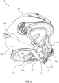
- the helmet 100 is configured to protect the head of a user and comprises a cap 101 and an internal cavity 102, positioned inside said cap 101 and intended to accommodate the head of a user. Furthermore, the internal cavity 102 has an access zone 121, configured to allow access of the user's head inside the internal cavity 102.
- the cap 101 has a front portion 115 defining a front opening preferably connected to the access zone 121, namely in such a way that the front opening and the access zone 121 form preferably a single opening in the cap 101.
- the cap also has a rear portion 116, opposite to the front portion 115.
- the helmet 100 also comprises a chin strap device 10 comprising in turn at least one belt structure 11, which is fixed between two side portions 117, 118, namely between a right side portion and a left side portion, of the cap 101.
- a chin strap device 10 comprising in turn at least one belt structure 11, which is fixed between two side portions 117, 118, namely between a right side portion and a left side portion, of the cap 101.
- each side portion of the two side portions 117, 118 is comprised between the front portion 115 and the rear portion 116 and the belt structure 11 extends at least between the side portions 117 and the zone 121 for access to the internal cavity 102.
- the belt structure is fixed on an inner side of the cap, namely along an inner surface of the cap facing the internal cavity.
- the belt structure 11 extends between a fixing point on a side portion 117 and a fixing point on the other side portion 118 of the cap 101, crossing a lower region of the helmet 100 where the access zone 121 is located. Even more preferably, in connection with the fixing point, the belt structure 11 is fixed to the side portion 117 of the cap 101 in the vicinity of at least one temple zone of the head of a user wearing the helmet 100.
- a zone of a side portion 117 comprised between the belt structure 11 and the front opening is a front side zone 117a of the cap 101 and a zone of the side portion 117 comprised between the belt structure 11 and the rear portion 116 is a rear side zone 117b of the cap 101.
- the belt structure 11 divides the side portion 117 into a front side portion 117a, positioned towards the front opening, and a rear side zone 117b, positioned towards the rear portion 116.
- the helmet also comprises at least one tie element 12a, 12b which extends along the front side zone 117a.
- a first part or end of the at least one tie element 12a, 12b is connected to the front side zone 117a of the cap, and a second part or end, preferably opposite to the first end, is connected to the belt structure 11.
- the at least one tie element 12a,12b is a first tie element 12a, 12b and the helmet comprises at least one second tie element 13a, 13b which extends along the rear side zone 117b.
- a first part of the at least one second tie element 13a, 13b is connected to the rear side zone 117b of the cap 101 and a second part of the at least one second tie element 13a, 13b is connected to the belt structure 11.
- tie element refers to a preferably ribbon or band or strip like element or an element with any similar form.
- a tie element is preferably configured to be tensioned between two points for fixing or connection to other elements of the helmet, for example the belt structure, so as to oppose or prevent rotation of the cap with respect to the head of the user, for example a rotation tending to expose at least partially a frontal zone of the head and/or an occipital zone.
- the belt structure 11 is fixed to the cap 101 in the vicinity of a temple zone of the user's head and is configured to engage with or be coupled with the user's head in a jaw zone so as to keep the user's head inside the internal cavity 102 and therefore prevent removal of the helmet 100.
- the at least one tie element 12a, 12b is associated with the cap 101 in the vicinity of a cheekbone zone of the user and is connected to or fastened or wound around the belt structure 11, so as to be able to engage with it or be coupled to it in order to oppose rotation of the cap 101 with respect to the user's head, in particular a rotation tending to expose during use a frontal zone of the head.
- the second tie element 13a, 13b operates in a similar manner and opposes rotation of the cap tending to expose during use an occipital zone of the head.
- the helmet comprises a second side portion 118, or left side portion, comprised between the front portion 115 and the rear portion 116 and opposite to the first side portion 117.
- the belt structure 11 extends between the first side portion 117 and the second side portion 118.
- the first side portion 117 may be right side portion of the cap and the second side portion 118 may be a left side portion of the cap, or vice versa.
- a zone of the second side portion 118 comprised between the belt structure 11 and the front opening is a second front side zone 118a of the cap 101 and a zone of the second side portion 118 comprised between the belt structure 11 and the rear portion 116 is a second rear side zone 118b of the cap 101.
- the at least one tie element 12a, 12b is one of a pair of tie elements 12a, 12b, wherein a first tie element of the pair of tie elements 12a, 12b extends along the first front side zone 117a of the cap 101 and the other tie element of the pair of tie elements 12a, 12b extends along the second front side zone 118 of the cap 101.
- each tie element 12a, 12b of the pair of tie elements 12a, 12b is connected to the respective front side zone, for example right or left side zone, and is furthermore connected to the belt structure in the respective side portion of the cap 101.
- each of the pair of tie elements 12a, 12b is associated with the cap 101 in the vicinity of the respective cheekbone zone of the user's head, for example in a right or left zone of the cap.
- the at least one second tie element 13a, 13b is configured to be tensioned in the event of rotation of the cap 101 so as to oppose or prevent rotation of the cap 101 with respect to the user's head, in particular a rotation tending to expose during use an occipital zone of the user's head.
- the pair of tie elements 12a, 12b is a pair of first tie elements 12a, 12b and the at least one second tie element 13a, 13b is one of a pair of second tie elements 13a, 13b.
- a first tie element of the pair of second tie elements 13a, 13b extends along the first rear side zone 117b of the cap 101 and the other tie element of the pair of tie elements 13a, 13b extends along the second rear side zone 118b of the cap 101.
- the first rear side zone 117b is one of a rear, right, side zone and a rear, left, side zone of the cap
- the second rear side zone 118b is the other one of a rear, right, side zone and a rear, left, side zone of the cap.
- each of the pair of second tie elements is connected to the respective rear side zone and each one is furthermore connected to the belt structure in the respective side portion of the cap, for example the right or left side portion.
- the belt structure 11 comprises a first belt portion 11a and a second belt portion 11b and comprises furthermore a mutual connection mechanism 11c.
- the first belt portion 11a is fixed onto the first side portion 117 of the cap 101 and the second belt portion 11b is fixed onto the second side portion 118 of the cap 101.
- the mutual connection mechanism 11c is configured to connect in a removable manner a free end of the first belt portion 11a with a free end of the second belt portion 11b.
- the belt structure 11 forms a continuous structure which extends from the first side portion 117 of the cap 101 to the second side portion 118 of the cap 101.
- the mutual connection mechanism 11c may separate the first belt portion 11a and the second belt portion 11b, for example so as to allow removal of the helmet from the user's head.
- the mutual connection device 11c may also be configured to allow lengthening or shortening of the belt structure 11, for example so as to allow more efficient adaptation of the belt structure 11 to the user's head.
- the second part of the at least one tie element 12a, 12b namely that connected to the belt structure 11, has a ring or a loop and the belt structure 11 is inserted so as to pass through and/or slide in the ring or loop.
- each of the pair of first tie elements 12a, 12b is connected to the belt structure 11 by means of a ring or a loop, inside which the belt structure 11 is inserted so as to pass through it and/or slide therein.
- the first belt portion 11a is inserted so as to pass through and/or slide in a ring or loop of one of the pair of first tie elements 12a, 12b, while the second belt portion 11b is inserted so as to pass through and/or slide in a ring or loop of the other one of the pair of first tie elements 12a, 12b.
- the at least one tie element 12a, 12b is configured to slide with respect to the belt structure 11.
- the belt structure 11 is slidably inserted in a ring portion or loop portion 112 of the at least one tie element 12a, 12b.
- the second part of the at least one second tie element 13a, 13b, namely that connected to the belt structure 11, has a ring or a loop and the belt structure 11 is inserted so as to pass through and/or slide in the ring or loop.
- each of the pair of second tie elements 13a, 13b is connected to the belt structure 11 by means of a ring or a loop, inside which the belt structure 11 is inserted so as to pass through it and/or slide therein.
- the first belt portion 11a is inserted so as to pass through and/or slide in a ring or loop of one of the pair of second tie elements 13a, 13b, while the second belt portion 11b is inserted so as to pass through and/or slide in a ring or loop of the other one of the pair of second tie elements 13a, 13b.
- the first part of the at least one tie element 12a, 12b is connected to the front side zone 117b of the cap 101 in a front fixing zone 127a
- the first part of the at least one second tie element 13a, 13b is connected to the rear side zone 117b of the cap 101 in a rear fixing zone 127b.
- the front fixing zone 127a is closer to the belt structure 11 than the rear fixing zone 127b.
- the belt structure 11 is arranged between the front fixing zone 127a and the rear fixing zone 127b and is closer to the front fixing zone 127a than the rear fixing zone 127b.
- the protective helmet according to the present disclosure is a helmet without chin guard protection or a helmet comprising a removable chin guard, or a helmet comprising a chin guard which can be opened.
- the helmet may be a jet or demi-jet helmet or a modular helmet, or a full-face helmet with a chin guard which can be opened.
- the method furthermore involves:
- the at least one first tie element 12a, 12b is one of a pair of tie elements 12a, 12b and the other tie element of the pair of tie elements 12a, 12b extends along a second front side zone 118a of the cap 101, positioned on the second side portion 118 and comprised between the front portion 115 and the belt structure 11. Furthermore, preferably a first part of the other tie element of the pair of first tie elements 12a, 12b is connected to the cap 101 in the second front side zone 118a, and a second part of the other tie element of the pair of first tie elements 12a, 12b is connected to the belt structure 11. Furthermore, when the cap 101 rotates in a rotational movement, the belt structure 11 and the pair of first tie elements 12a, 12b are under tension.
- the belt structure 11 and the pair of first tie elements 12a, 12b are tensioned so as to oppose the rotational movement with respect to the user's head tending to expose at least partially, during use, a frontal zone of the user's head, namely oppose or prevent the so-called roll-off movement.
- the helmet 100 further comprises a pair of second tie elements 13a, 13b.
- said second tie element is one tie element of the pair of second tie elements 13a, 13b which extends along a first rear side zone 117b of the cap 101, positioned on the first side portion 117 and comprised between the rear portion 116 and the belt structure 111, and the other tie element of the pair of second tie elements 13a, 13b extends along a second rear side zone 118b of the cap 101, positioned on the second side portion 118 and comprised between the rear portion 116 and the belt structure 11.
- a first part of said one tie element of the pair of second tie elements 13a, 13b is connected to the cap 101 in the first rear side zone 117b, and a second part of said tie element of said pair of second tie elements 13a, 13b is connected to the belt structure 11, and wherein a first part of the other tie element of the pair of second tie elements 13a, 13b is connected to the cap 101 in the second rear side zone 118b, and a second part of the other tie element of the pair of second tie elements 13a, 13b is connected to the belt structure 11.
- the belt structure 11 and the pair of first tie elements 12a, 12b are under tension when the cap rotates in a first rotational movement tending to expose a frontal zone of the head of a user
- the belt structure 11 and the pair of second tie elements 13a, 13b are under tension when the cap rotates in a second rotational movement tending to expose an occipital zone of the head of a user.
- each of the pair of first tie elements 12a, 12b has a ring or loop 112 in the region where it is connected to the belt structure 11, and the latter slides inside the ring or loop.
- the second part of one of the pair of second tie elements 13a, 13b, which is connected to the belt structure 11, has a ring portion or loop portion 112 and the second pair of the other one of the pair of second tie elements 13a, 13b connected to the belt structure 11 has likewise a ring portion or loop portion.
- the belt structure 11 slides in the ring or loop of one of the pair of second tie elements 13a, 13b and of the other one of the pair of second tie elements 13a, 13b.
- each of the pair of first tie elements 12a, 12b and each of the pair of second tie elements 13a, 13b is preferably connected to the belt structure 11 by means of a ring or loop, inside which the belt structure 11 slides.
Landscapes
- Helmets And Other Head Coverings (AREA)
Claims (15)
- Helm (100) zum Schützen des Kopfs eines Benutzers, wobei der Helm (100) eine Kappe (101) und einen inneren Hohlraum (102) umfasst, der eine Zugangszone (121) aufweist und vorgesehen ist, um den Kopf eines Benutzers aufzunehmen,wobei die Kappe (101) einen vorderen Abschnitt (115), der eine vordere Öffnung definiert, und einen hinteren Abschnitt (116) aufweist,wobei der Helm (100) eine Kinnriemenvorrichtung (10), umfassend mindestens eine Gurtstruktur (11), umfasst,wobei die Gurtstruktur (11) zwischen Seitenabschnitten (117) oder einem rechten und einem linken Seitenabschnitt der Kappe (101) befestigt ist, die jeweils zwischen dem vorderen Abschnitt (115) und dem hinteren Abschnitt (116) eingeschlossen sind, und wobei sich die Gurtstruktur (11) mindestens zwischen den Seitenabschnitten (117) und der Zone (121) für einen Zugang zu dem inneren Hohlraum (102) erstreckt,und wobei eine Zone eines Seitenabschnitts (117) der Seitenabschnitte, die zwischen der Gurtstruktur (11) und der vorderen Öffnung eingeschlossen ist, eine vordere Seitenzone (117a) der Kappe ist und eine Zone des Seitenabschnitts (117), die zwischen der Gurtstruktur (11) und dem hinteren Abschnitt (116) eingeschlossen ist, eine hintere Seitenzone (117b) der Kappe ist,und wobei der Helm mindestens ein Zugelement (12a, 12b), das sich entlang der vorderen Seitenzone (117a) erstreckt, umfasst, und wobei ein erster Teil des mindestens einen Zugelements (12a, 12b) mit der vorderen Seitenzone (117a) der Kappe (101) verbunden ist und ein zweiter Teil des mindestens einen Zugelements (12a, 12b) mit der Gurtstruktur (11) verbunden ist, und
dadurch gekennzeichnet, dass das mindestens eine Zugelement (12a, 12b) ein erstes Zugelement (12a, 12b) ist und der Helm mindestens ein zweites Zugelement (13a, 13b) umfasst, das sich entlang der hinteren Seitenzone (117b) erstreckt, und wobei ein erster Teil des mindestens einen zweiten Zugelements (13a, 13b) mit der hinteren Seitenzone (117b) der Kappe (101) verbunden ist und ein zweiter Teil des mindestens einen zweiten Zugelements (13a, 13b) mit der Gurtstruktur (11) verbunden ist. - Helm (100) nach dem vorstehenden Anspruch, wobei der Seitenabschnitt ein erster Seitenabschnitt (117), oder rechter Seitenabschnitt, ist und die vordere Seitenzone (117a) eine erste vordere Seitenzone (117a) ist und die hintere Seitenzone (117b) eine erste hintere Seitenzone (117b) istund wobei der Helm einen zweiten Seitenabschnitt (118) oder linken Seitenabschnitt, der zwischen dem vorderen Abschnitt (115) und dem hinteren Abschnitt (116) eingeschlossen ist und dem ersten Seitenabschnitt (117) gegenüberliegt, umfasst, und wobei sich die Gurtstruktur (11) zwischen dem ersten Seitenabschnitt (117) und dem zweiten Seitenabschnitt (118) erstreckt,und wobei eine Zone des zweiten Seitenabschnitts (118), die zwischen der Gurtstruktur (11) und der vorderen Öffnung eingeschlossen ist, eine zweite vordere Seitenzone (118a) der Kappe (101) ist, und eine Zone des zweiten Seitenabschnitts (118), die zwischen der Gurtstruktur (11) und dem hinteren Abschnitt (116) eingeschlossen ist, eine zweite hintere Seitenzone (118b) der Kappe (101) ist,und wobei das erste Zugelement (12a, 12b) eines von einem Paar Zugelemente (12a, 12b) ist, wobei sich eines von dem Paar Zugelemente (12a, 12b) entlang der ersten vorderen Seitenzone (117a) der Kappe (101) erstreckt und sich das andere eine von dem Paar Zugelemente (12a, 12b) entlang der zweiten vorderen Seitenzone (118a) der Kappe (101) erstreckt.
- Helm (100) nach dem vorstehenden Anspruch, wobei das Paar Zugelemente (12a, 12b) ein Paar erster Zugelemente (12a, 12b) ist, und wobei das mindestens eine zweite Zugelement (13a, 13b) eines von einem Paar zweiter Zugelemente (13a, 13b) ist, wobei sich eines von dem Paar zweiter Zugelemente (13a, 13b) entlang der ersten hinteren Seitenzone (117b) der Kappe (101) erstreckt und sich das andere eine von dem Paar Zugelemente (13a, 13b) entlang der zweiten hinteren Seitenzone (118b) der Kappe (101) erstreckt.
- Helm (100) nach einem der Ansprüche 2 oder 3, wobei die Gurtstruktur (11) einen ersten Gurtabschnitt (11a) und einen zweiten Gurtabschnitt (11b) und einen gemeinsamen Verbindungsmechanismus (11c) umfasst,wobei der erste Gurtabschnitt (11a) an dem ersten Seitenabschnitt (117) der Kappe (101) befestigt ist und der zweite Gurtabschnitt (11b) an dem zweiten Seitenabschnitt (118) der Kappe (101) befestigt ist,und wobei der gemeinsame Verbindungsmechanismus (11c) konfiguriert ist, um ein freies Ende des ersten Gurtabschnitts (11a) auf eine lösbare Weise mit einem freien Ende des zweiten Gurtabschnitts (11b) zu verbinden.
- Helm (100) nach einem der vorstehenden Ansprüche, wobei der zweite Teil des mindestens einen Zugelements (12a, 12b), das mit der Gurtstruktur (11) verbunden ist, einen Ring oder eine Schlaufe aufweist und wobei die Gurtstruktur (11) so eingeführt wird, dass sie durch den Ring oder die Schlaufe hindurchgeht und/oder in diesen gleitet.
- Helm (100) nach einem der vorstehenden Ansprüche, wobei der zweite Teil des mindestens einen zweiten Zugelements (13a, 13b), das mit der Gurtstruktur (11) verbunden ist, einen Ring oder eine Schlaufe aufweist und wobei die Gurtstruktur (11) so eingeführt wird, dass sie durch den Ring oder die Schlaufe hindurchgeht und/oder in diesen gleitet.
- Helm (100) nach einem der vorstehenden Ansprüche, wobei der erste Teil des mindestens einen Zugelements (12a, 12b) in einer vorderen Befestigungszone (127a) mit der vorderen Seitenzone (117b) der Kappe (101) verbunden ist,und wobei der erste Teil des mindestens einen zweiten Zugelements (13a, 13b) in einer hinteren Befestigungszone (127b) mit der hinteren Seitenzone (117b) der Kappe (101) verbunden ist,und wobei sich die vordere Befestigungszone (127a) näher an der Gurtstruktur (11) als die hintere Befestigungszone (127b) befindet.
- Helm (100) nach einem der vorstehenden Ansprüche, wobei das mindestens eine erste Zugelement (12a, 12b) eine kürzere Länge als das mindestens eine zweite Zugelement (13a, 13b) aufweist.
- Helm (100) nach einem der vorstehenden Ansprüche, wobei der Helm (100) ein Helm ohne einen Kinnbügel oder ein Helm umfassend einen abnehmbaren Kinnbügel oder ein Helm umfassend einen Kinnbügel, der geöffnet werden kann, ist.
- Verwendung eines Helms (100) nach einem der vorstehenden Ansprüche für den Schutz des Kopfs eines Benutzers.
- Verfahren zum Schützen des Kopfs eines Benutzers mittels eines Helms (100), umfassend eine Kappe (101), wobei die Kappe (101) einen vorderen Abschnitt (115), der eine vordere Öffnung definiert, und einen hinteren Abschnitt (116) umfasst, und wobei der Helm ferner einen inneren Hohlraum (102) umfasst, der eine Zugangszone (121) aufweist und vorgesehen ist, um den Kopf eines Benutzers aufzunehmen, wobei das Verfahren beinhaltet:- Bereitstellen einer Gurtstruktur (11), die an einem ersten Seitenabschnitt (117) der Kappe (101), der zwischen dem vorderen Abschnitt (115) und dem hinteren Abschnitt (116) eingeschlossen ist, und an einem zweiten Seitenabschnitt (118), der zwischen dem vorderen Abschnitt (115) und dem hinteren Abschnitt (116) eingeschlossen ist und dem ersten Seitenabschnitt (117) gegenüberliegt, befestigt ist,- Bereitstellen von mindestens einem ersten Zugelement (12a, 12b), das sich entlang einer ersten vorderen Seitenzone (117a) der Kappe (101) erstreckt, an dem ersten Seitenabschnitt (117) positioniert ist und zwischen dem vorderen Abschnitt (115) und der Gurtstruktur (11) eingeschlossen ist, wobei ein erster Teil des mindestens einen Zugelements (12a, 12b), in der ersten vorderen Seitenzone (117a), mit der Kappe (101) verbunden ist und ein zweiter Teil des mindestens einen Zugelements (12a, 12b) mit der Gurtstruktur (11) verbunden ist,- Bereitstellen von mindestens einem zweiten Zugelement (13a, 13b), das sich entlang einer hinteren Seitenzone (117b) der Kappe erstreckt, an dem ersten Seitenabschnitt (117) positioniert ist und zwischen dem hinteren Abschnitt (116) und der Gurtstruktur (11) eingeschlossen ist, und wobei ein erster Teil des mindestens einen zweiten Zugelements (13a, 13b) mit der hinteren Seitenzone (117b) der Kappe (101) verbunden ist und ein zweiter Teil des mindestens einen zweiten Zugelements (13a, 13b) mit der Gurtstruktur (11) verbunden ist,wobei, wenn sich die Kappe (101) in einer Drehbewegung dreht, die Gurtstruktur (11) und das mindestens eine erste Zugelement (12a, 12b) und/oder zweite Zugelement (13a, 13b) unter Spannung stehen.
- Verfahren nach dem vorstehenden Anspruch, wobei das mindestens eine erste Zugelement (12a, 12b) eines von einem Paar erster Zugelemente (12a, 12b) ist, wobei sich das andere eine von dem Paar erster Zugelemente (12a, 12b) entlang einer zweiten vorderen Seitenzone (118a) der Kappe (101) erstreckt, an dem zweiten Seitenabschnitt (118) positioniert ist und zwischen dem vorderen Abschnitt (115) und der Gurtstruktur (11) eingeschlossen ist,und wobei ein erster Teil des anderen einen des Paars Zugelemente (12a, 12b) mit der Kappe (101) in der zweiten vorderen Seitenzone (118a) verbunden ist, und ein zweiter Teil des anderen einen des Paars erster Zugelemente (12a, 12b) mit der Gurtstruktur (11) verbunden ist,wobei, wenn sich die Kappe (101) in einer Drehbewegung dreht, die Gurtstruktur (11) und das Paar erster Zugelemente (12a, 12b) unter Spannung stehen.
- Verfahren nach dem vorstehenden Anspruch, wobei mindestens ein zweites Zugelement (13a, 13b) eines von einem Paar zweiter Zugelemente (13a, 13b) ist und sich das andere eine von dem Paar zweiter Zugelemente (13a, 13b) entlang einer zweiten hinteren Seitenzone (118b) der Kappe (101) erstreckt, an dem zweiten Seitenabschnitt (118) positioniert ist und zwischen dem hinteren Abschnitt (116) und der Gurtstruktur (11) eingeschlossen ist,wobei ein erster Teil von einem des Paars zweiter Zugelemente (13a, 13b) mit der Kappe (101) in der ersten hinteren Seitenzone (117b) verbunden ist, und ein zweiter Teil des einen des Paars zweiter Zugelemente (13a, 13b) mit der Gurtstruktur (11) verbunden ist, und wobei ein erster Teil des anderen einen des Paars zweiter Zugelemente (13a, 13b) mit der Kappe (101) in der zweiten hinteren Seitenzone (118b) verbunden ist, und ein zweiter Teil des anderen einen des Paars zweiter Zugelemente (13a, 13b) mit der Gurtstruktur (11) verbunden ist,wobei, wenn sich die Kappe (101) in einer ersten Drehbewegung zu dem hinteren Abschnitt hin dreht, die Gurtstruktur (11) und das Paar erster Zugelemente (12a, 12b) unter Spannung stehen und/oder, wenn sich die Kappe (101) in einer zweiten Drehbewegung zu dem vorderen Abschnitt hin dreht, das Paar zweiter Zugelemente (13a, 13b) unter Spannung steht.
- Verfahren nach dem vorstehenden Anspruch, wobei der zweite Teil des mindestens einen Zugelements (12a, 12b), das mit der Gurtstruktur (11) verbunden ist, einen Ring oder eine Schlaufe aufweist und wobei die Gurtstruktur (11), gemäß dem Verfahren, in dem Ring oder der Schlaufe gleitet.
- Verfahren nach Anspruch 13 oder 14, wobei der zweite Teil des einen des Paars zweiter Zugelemente (13a, 13b), das mit der Gurtstruktur (11) verbunden ist, einen Ring oder eine Schleife aufweist und der zweite Teil des anderen einen des Paars zweiter Zugelemente (13a, 13b), das mit der Gurtstruktur (11) verbunden ist, einen Ring oder eine Schleife aufweist, und
wobei die Gurtstruktur (11), gemäß dem Verfahren, in dem Ring oder der Schleife des einen des Paars zweiter Zugelemente (13a, 13b) und in dem Ring oder der Schleife des anderen einen des Paars zweiter Zugelemente (13a, 13b) gleitet.
Applications Claiming Priority (1)
| Application Number | Priority Date | Filing Date | Title |
|---|---|---|---|
| IT202200013912 | 2022-06-30 |
Publications (3)
| Publication Number | Publication Date |
|---|---|
| EP4298941A1 EP4298941A1 (de) | 2024-01-03 |
| EP4298941C0 EP4298941C0 (de) | 2025-04-30 |
| EP4298941B1 true EP4298941B1 (de) | 2025-04-30 |
Family
ID=83271234
Family Applications (1)
| Application Number | Title | Priority Date | Filing Date |
|---|---|---|---|
| EP23179596.4A Active EP4298941B1 (de) | 2022-06-30 | 2023-06-15 | Schutzhelm |
Country Status (1)
| Country | Link |
|---|---|
| EP (1) | EP4298941B1 (de) |
Family Cites Families (3)
| Publication number | Priority date | Publication date | Assignee | Title |
|---|---|---|---|---|
| DE8320129U1 (de) * | 1983-07-13 | 1984-01-26 | Hein Gericke GmbH & Co KG, 4000 Düsseldorf | Integral-Sturzhelm für Fahrzeugführer |
| DE8514219U1 (de) * | 1985-05-14 | 1985-06-27 | Fa. air Technik, 6382 Friedrichsdorf | Schutzhelm |
| EP3641578B1 (de) * | 2017-06-21 | 2021-09-15 | Darryl Rodney Flack | Helmkinnriemen |
-
2023
- 2023-06-15 EP EP23179596.4A patent/EP4298941B1/de active Active
Also Published As
| Publication number | Publication date |
|---|---|
| EP4298941A1 (de) | 2024-01-03 |
| EP4298941C0 (de) | 2025-04-30 |
Similar Documents
| Publication | Publication Date | Title |
|---|---|---|
| US8209784B2 (en) | Helmet with an attachment mechanism for a faceguard | |
| US6772447B2 (en) | Protective sport helmet | |
| KR20130006254A (ko) | 헬멧 | |
| AU4754096A (en) | Collapsible helmet | |
| US11612206B2 (en) | Detachable pad fastening structure of helmet and helmet including same | |
| EP3162235B1 (de) | Stirnstütze für helme und helm mit einer deratigen stirnstütze | |
| US8856973B2 (en) | Goalie helmet with novel strap configuration | |
| KR20190008802A (ko) | 비상시 패드 제거가 가능한 헬멧 | |
| US7131148B1 (en) | Combined bandana and goggles | |
| EP4298941B1 (de) | Schutzhelm | |
| CN115426911A (zh) | 保护头盔 | |
| EP1199000B1 (de) | Schutzhelm, insbesondere für Kampfsportarten | |
| CN108391884B (zh) | 一种头盔 | |
| PT9181U (pt) | Capacete de proteccao | |
| US20210345721A1 (en) | Non-Impact Construction Face Shield | |
| US20240156200A1 (en) | Shell for protective helmet and associated protective helmet | |
| KR101957301B1 (ko) | 탄성구속부가 구비된 안전진단 점검용 안전모 | |
| US20080109946A1 (en) | Goalie helmet with novel strap configuration | |
| KR102049070B1 (ko) | 안전모용 걸이구 | |
| KR102296424B1 (ko) | 안전모용 머리받침 밴드 및 이를 갖는 안전모 | |
| CA2565753C (en) | Goalie helmet with novel strap configuration | |
| KR200272407Y1 (ko) | 안전모용 라이너 결합구조 | |
| KR200212170Y1 (ko) | 헤드밴드형 귀마개 | |
| KR100893922B1 (ko) | 안전 헬멧용 턱 커튼 | |
| KR20210002374U (ko) | 호흡용 마스크의 귀 보호 지지장치 |
Legal Events
| Date | Code | Title | Description |
|---|---|---|---|
| PUAI | Public reference made under article 153(3) epc to a published international application that has entered the european phase |
Free format text: ORIGINAL CODE: 0009012 |
|
| STAA | Information on the status of an ep patent application or granted ep patent |
Free format text: STATUS: THE APPLICATION HAS BEEN PUBLISHED |
|
| AK | Designated contracting states |
Kind code of ref document: A1 Designated state(s): AL AT BE BG CH CY CZ DE DK EE ES FI FR GB GR HR HU IE IS IT LI LT LU LV MC ME MK MT NL NO PL PT RO RS SE SI SK SM TR |
|
| STAA | Information on the status of an ep patent application or granted ep patent |
Free format text: STATUS: REQUEST FOR EXAMINATION WAS MADE |
|
| 17P | Request for examination filed |
Effective date: 20240610 |
|
| RBV | Designated contracting states (corrected) |
Designated state(s): AL AT BE BG CH CY CZ DE DK EE ES FI FR GB GR HR HU IE IS IT LI LT LU LV MC ME MK MT NL NO PL PT RO RS SE SI SK SM TR |
|
| GRAP | Despatch of communication of intention to grant a patent |
Free format text: ORIGINAL CODE: EPIDOSNIGR1 |
|
| STAA | Information on the status of an ep patent application or granted ep patent |
Free format text: STATUS: GRANT OF PATENT IS INTENDED |
|
| INTG | Intention to grant announced |
Effective date: 20241204 |
|
| GRAS | Grant fee paid |
Free format text: ORIGINAL CODE: EPIDOSNIGR3 |
|
| GRAA | (expected) grant |
Free format text: ORIGINAL CODE: 0009210 |
|
| STAA | Information on the status of an ep patent application or granted ep patent |
Free format text: STATUS: THE PATENT HAS BEEN GRANTED |
|
| AK | Designated contracting states |
Kind code of ref document: B1 Designated state(s): AL AT BE BG CH CY CZ DE DK EE ES FI FR GB GR HR HU IE IS IT LI LT LU LV MC ME MK MT NL NO PL PT RO RS SE SI SK SM TR |
|
| REG | Reference to a national code |
Ref country code: CH Ref legal event code: EP Ref country code: GB Ref legal event code: FG4D |
|
| REG | Reference to a national code |
Ref country code: DE Ref legal event code: R096 Ref document number: 602023003144 Country of ref document: DE |
|
| REG | Reference to a national code |
Ref country code: IE Ref legal event code: FG4D |
|
| U01 | Request for unitary effect filed |
Effective date: 20250523 |
|
| U07 | Unitary effect registered |
Designated state(s): AT BE BG DE DK EE FI FR IT LT LU LV MT NL PT RO SE SI Effective date: 20250530 |
|
| U20 | Renewal fee for the european patent with unitary effect paid |
Year of fee payment: 3 Effective date: 20250619 |
|
| PG25 | Lapsed in a contracting state [announced via postgrant information from national office to epo] |
Ref country code: ES Free format text: LAPSE BECAUSE OF FAILURE TO SUBMIT A TRANSLATION OF THE DESCRIPTION OR TO PAY THE FEE WITHIN THE PRESCRIBED TIME-LIMIT Effective date: 20250430 |
|
| PG25 | Lapsed in a contracting state [announced via postgrant information from national office to epo] |
Ref country code: NO Free format text: LAPSE BECAUSE OF FAILURE TO SUBMIT A TRANSLATION OF THE DESCRIPTION OR TO PAY THE FEE WITHIN THE PRESCRIBED TIME-LIMIT Effective date: 20250730 Ref country code: GR Free format text: LAPSE BECAUSE OF FAILURE TO SUBMIT A TRANSLATION OF THE DESCRIPTION OR TO PAY THE FEE WITHIN THE PRESCRIBED TIME-LIMIT Effective date: 20250731 |
|
| PG25 | Lapsed in a contracting state [announced via postgrant information from national office to epo] |
Ref country code: PL Free format text: LAPSE BECAUSE OF FAILURE TO SUBMIT A TRANSLATION OF THE DESCRIPTION OR TO PAY THE FEE WITHIN THE PRESCRIBED TIME-LIMIT Effective date: 20250430 |
|
| PG25 | Lapsed in a contracting state [announced via postgrant information from national office to epo] |
Ref country code: HR Free format text: LAPSE BECAUSE OF FAILURE TO SUBMIT A TRANSLATION OF THE DESCRIPTION OR TO PAY THE FEE WITHIN THE PRESCRIBED TIME-LIMIT Effective date: 20250430 |
|
| PG25 | Lapsed in a contracting state [announced via postgrant information from national office to epo] |
Ref country code: RS Free format text: LAPSE BECAUSE OF FAILURE TO SUBMIT A TRANSLATION OF THE DESCRIPTION OR TO PAY THE FEE WITHIN THE PRESCRIBED TIME-LIMIT Effective date: 20250731 |
|
| PG25 | Lapsed in a contracting state [announced via postgrant information from national office to epo] |
Ref country code: IS Free format text: LAPSE BECAUSE OF FAILURE TO SUBMIT A TRANSLATION OF THE DESCRIPTION OR TO PAY THE FEE WITHIN THE PRESCRIBED TIME-LIMIT Effective date: 20250830 |
|
| PG25 | Lapsed in a contracting state [announced via postgrant information from national office to epo] |
Ref country code: SM Free format text: LAPSE BECAUSE OF FAILURE TO SUBMIT A TRANSLATION OF THE DESCRIPTION OR TO PAY THE FEE WITHIN THE PRESCRIBED TIME-LIMIT Effective date: 20250430 |
|
| PG25 | Lapsed in a contracting state [announced via postgrant information from national office to epo] |
Ref country code: CZ Free format text: LAPSE BECAUSE OF FAILURE TO SUBMIT A TRANSLATION OF THE DESCRIPTION OR TO PAY THE FEE WITHIN THE PRESCRIBED TIME-LIMIT Effective date: 20250430 |
|
| PG25 | Lapsed in a contracting state [announced via postgrant information from national office to epo] |
Ref country code: SK Free format text: LAPSE BECAUSE OF FAILURE TO SUBMIT A TRANSLATION OF THE DESCRIPTION OR TO PAY THE FEE WITHIN THE PRESCRIBED TIME-LIMIT Effective date: 20250430 |
|
| PG25 | Lapsed in a contracting state [announced via postgrant information from national office to epo] |
Ref country code: MC Free format text: LAPSE BECAUSE OF FAILURE TO SUBMIT A TRANSLATION OF THE DESCRIPTION OR TO PAY THE FEE WITHIN THE PRESCRIBED TIME-LIMIT Effective date: 20250430 |