EP4296829A2 - Verbesserungen an und im zusammenhang mit anzeigen - Google Patents
Verbesserungen an und im zusammenhang mit anzeigen Download PDFInfo
- Publication number
- EP4296829A2 EP4296829A2 EP23208742.9A EP23208742A EP4296829A2 EP 4296829 A2 EP4296829 A2 EP 4296829A2 EP 23208742 A EP23208742 A EP 23208742A EP 4296829 A2 EP4296829 A2 EP 4296829A2
- Authority
- EP
- European Patent Office
- Prior art keywords
- display
- light
- displayed
- light components
- display device
- Prior art date
- Legal status (The legal status is an assumption and is not a legal conclusion. Google has not performed a legal analysis and makes no representation as to the accuracy of the status listed.)
- Pending
Links
Images


Classifications
-
- G—PHYSICS
- G02—OPTICS
- G02B—OPTICAL ELEMENTS, SYSTEMS OR APPARATUS
- G02B27/00—Optical systems or apparatus not provided for by any of the groups G02B1/00 - G02B26/00, G02B30/00
- G02B27/01—Head-up displays
- G02B27/017—Head mounted
- G02B27/0172—Head mounted characterised by optical features
-
- G—PHYSICS
- G09—EDUCATION; CRYPTOGRAPHY; DISPLAY; ADVERTISING; SEALS
- G09G—ARRANGEMENTS OR CIRCUITS FOR CONTROL OF INDICATING DEVICES USING STATIC MEANS TO PRESENT VARIABLE INFORMATION
- G09G3/00—Control arrangements or circuits, of interest only in connection with visual indicators other than cathode-ray tubes
- G09G3/001—Control arrangements or circuits, of interest only in connection with visual indicators other than cathode-ray tubes using specific devices not provided for in groups G09G3/02 - G09G3/36, e.g. using an intermediate record carrier such as a film slide; Projection systems; Display of non-alphanumerical information, solely or in combination with alphanumerical information, e.g. digital display on projected diapositive as background
- G09G3/003—Control arrangements or circuits, of interest only in connection with visual indicators other than cathode-ray tubes using specific devices not provided for in groups G09G3/02 - G09G3/36, e.g. using an intermediate record carrier such as a film slide; Projection systems; Display of non-alphanumerical information, solely or in combination with alphanumerical information, e.g. digital display on projected diapositive as background to produce spatial visual effects
-
- H—ELECTRICITY
- H04—ELECTRIC COMMUNICATION TECHNIQUE
- H04N—PICTORIAL COMMUNICATION, e.g. TELEVISION
- H04N5/00—Details of television systems
- H04N5/44—Receiver circuitry for the reception of television signals according to analogue transmission standards
-
- G—PHYSICS
- G02—OPTICS
- G02B—OPTICAL ELEMENTS, SYSTEMS OR APPARATUS
- G02B27/00—Optical systems or apparatus not provided for by any of the groups G02B1/00 - G02B26/00, G02B30/00
- G02B27/0093—Optical systems or apparatus not provided for by any of the groups G02B1/00 - G02B26/00, G02B30/00 with means for monitoring data relating to the user, e.g. head-tracking, eye-tracking
-
- G—PHYSICS
- G02—OPTICS
- G02B—OPTICAL ELEMENTS, SYSTEMS OR APPARATUS
- G02B27/00—Optical systems or apparatus not provided for by any of the groups G02B1/00 - G02B26/00, G02B30/00
- G02B27/01—Head-up displays
- G02B27/017—Head mounted
-
- G—PHYSICS
- G02—OPTICS
- G02B—OPTICAL ELEMENTS, SYSTEMS OR APPARATUS
- G02B27/00—Optical systems or apparatus not provided for by any of the groups G02B1/00 - G02B26/00, G02B30/00
- G02B27/01—Head-up displays
- G02B27/0179—Display position adjusting means not related to the information to be displayed
-
- G—PHYSICS
- G06—COMPUTING OR CALCULATING; COUNTING
- G06F—ELECTRIC DIGITAL DATA PROCESSING
- G06F3/00—Input arrangements for transferring data to be processed into a form capable of being handled by the computer; Output arrangements for transferring data from processing unit to output unit, e.g. interface arrangements
- G06F3/01—Input arrangements or combined input and output arrangements for interaction between user and computer
- G06F3/011—Arrangements for interaction with the human body, e.g. for user immersion in virtual reality
- G06F3/012—Head tracking input arrangements
-
- G—PHYSICS
- G06—COMPUTING OR CALCULATING; COUNTING
- G06F—ELECTRIC DIGITAL DATA PROCESSING
- G06F3/00—Input arrangements for transferring data to be processed into a form capable of being handled by the computer; Output arrangements for transferring data from processing unit to output unit, e.g. interface arrangements
- G06F3/01—Input arrangements or combined input and output arrangements for interaction between user and computer
- G06F3/011—Arrangements for interaction with the human body, e.g. for user immersion in virtual reality
- G06F3/013—Eye tracking input arrangements
-
- G—PHYSICS
- G09—EDUCATION; CRYPTOGRAPHY; DISPLAY; ADVERTISING; SEALS
- G09G—ARRANGEMENTS OR CIRCUITS FOR CONTROL OF INDICATING DEVICES USING STATIC MEANS TO PRESENT VARIABLE INFORMATION
- G09G3/00—Control arrangements or circuits, of interest only in connection with visual indicators other than cathode-ray tubes
- G09G3/001—Control arrangements or circuits, of interest only in connection with visual indicators other than cathode-ray tubes using specific devices not provided for in groups G09G3/02 - G09G3/36, e.g. using an intermediate record carrier such as a film slide; Projection systems; Display of non-alphanumerical information, solely or in combination with alphanumerical information, e.g. digital display on projected diapositive as background
-
- G—PHYSICS
- G09—EDUCATION; CRYPTOGRAPHY; DISPLAY; ADVERTISING; SEALS
- G09G—ARRANGEMENTS OR CIRCUITS FOR CONTROL OF INDICATING DEVICES USING STATIC MEANS TO PRESENT VARIABLE INFORMATION
- G09G3/00—Control arrangements or circuits, of interest only in connection with visual indicators other than cathode-ray tubes
- G09G3/20—Control arrangements or circuits, of interest only in connection with visual indicators other than cathode-ray tubes for presentation of an assembly of a number of characters, e.g. a page, by composing the assembly by combination of individual elements arranged in a matrix no fixed position being assigned to or needed to be assigned to the individual characters or partial characters
- G09G3/2007—Display of intermediate tones
- G09G3/2018—Display of intermediate tones by time modulation using two or more time intervals
-
- G—PHYSICS
- G09—EDUCATION; CRYPTOGRAPHY; DISPLAY; ADVERTISING; SEALS
- G09G—ARRANGEMENTS OR CIRCUITS FOR CONTROL OF INDICATING DEVICES USING STATIC MEANS TO PRESENT VARIABLE INFORMATION
- G09G5/00—Control arrangements or circuits for visual indicators common to cathode-ray tube indicators and other visual indicators
- G09G5/02—Control arrangements or circuits for visual indicators common to cathode-ray tube indicators and other visual indicators characterised by the way in which colour is displayed
-
- G—PHYSICS
- G02—OPTICS
- G02B—OPTICAL ELEMENTS, SYSTEMS OR APPARATUS
- G02B27/00—Optical systems or apparatus not provided for by any of the groups G02B1/00 - G02B26/00, G02B30/00
- G02B27/01—Head-up displays
- G02B27/0179—Display position adjusting means not related to the information to be displayed
- G02B2027/0187—Display position adjusting means not related to the information to be displayed slaved to motion of at least a part of the body of the user, e.g. head, eye
-
- G—PHYSICS
- G02—OPTICS
- G02B—OPTICAL ELEMENTS, SYSTEMS OR APPARATUS
- G02B27/00—Optical systems or apparatus not provided for by any of the groups G02B1/00 - G02B26/00, G02B30/00
- G02B27/01—Head-up displays
- G02B2027/0192—Supplementary details
- G02B2027/0198—System for aligning or maintaining alignment of an image in a predetermined direction
-
- G—PHYSICS
- G09—EDUCATION; CRYPTOGRAPHY; DISPLAY; ADVERTISING; SEALS
- G09G—ARRANGEMENTS OR CIRCUITS FOR CONTROL OF INDICATING DEVICES USING STATIC MEANS TO PRESENT VARIABLE INFORMATION
- G09G2310/00—Command of the display device
- G09G2310/02—Addressing, scanning or driving the display screen or processing steps related thereto
- G09G2310/0235—Field-sequential colour display
-
- G—PHYSICS
- G09—EDUCATION; CRYPTOGRAPHY; DISPLAY; ADVERTISING; SEALS
- G09G—ARRANGEMENTS OR CIRCUITS FOR CONTROL OF INDICATING DEVICES USING STATIC MEANS TO PRESENT VARIABLE INFORMATION
- G09G2320/00—Control of display operating conditions
- G09G2320/02—Improving the quality of display appearance
- G09G2320/0247—Flicker reduction other than flicker reduction circuits used for single beam cathode-ray tubes
-
- G—PHYSICS
- G09—EDUCATION; CRYPTOGRAPHY; DISPLAY; ADVERTISING; SEALS
- G09G—ARRANGEMENTS OR CIRCUITS FOR CONTROL OF INDICATING DEVICES USING STATIC MEANS TO PRESENT VARIABLE INFORMATION
- G09G2320/00—Control of display operating conditions
- G09G2320/02—Improving the quality of display appearance
- G09G2320/0261—Improving the quality of display appearance in the context of movement of objects on the screen or movement of the observer relative to the screen
-
- G—PHYSICS
- G09—EDUCATION; CRYPTOGRAPHY; DISPLAY; ADVERTISING; SEALS
- G09G—ARRANGEMENTS OR CIRCUITS FOR CONTROL OF INDICATING DEVICES USING STATIC MEANS TO PRESENT VARIABLE INFORMATION
- G09G2320/00—Control of display operating conditions
- G09G2320/02—Improving the quality of display appearance
- G09G2320/0266—Reduction of sub-frame artefacts
-
- G—PHYSICS
- G09—EDUCATION; CRYPTOGRAPHY; DISPLAY; ADVERTISING; SEALS
- G09G—ARRANGEMENTS OR CIRCUITS FOR CONTROL OF INDICATING DEVICES USING STATIC MEANS TO PRESENT VARIABLE INFORMATION
- G09G2340/00—Aspects of display data processing
- G09G2340/04—Changes in size, position or resolution of an image
- G09G2340/0464—Positioning
-
- G—PHYSICS
- G09—EDUCATION; CRYPTOGRAPHY; DISPLAY; ADVERTISING; SEALS
- G09G—ARRANGEMENTS OR CIRCUITS FOR CONTROL OF INDICATING DEVICES USING STATIC MEANS TO PRESENT VARIABLE INFORMATION
- G09G2354/00—Aspects of interface with display user
Definitions
- This invention relates to display methods and devices for generating an image for display to a viewer.
- the invention provides a method and apparatus for generating images for viewing on displays in such a way as to increase display luminance and to reduce display 'flicker' as may arise when there is relative movement of the display and a viewer's direction of gaze.
- the invention may be applied in particular to substantially transparent head or helmet-mounted display (HMD) systems.
- HMD helmet-mounted display
- a method for controlling a display device as defined by claim 1.
- Optional further characterisations of the first aspect are as defined in claims 2 to 14.
- display brightness may be increased and the effective rate of displayed image refresh may also be increased without incurring problems of image smear or multiple image effects during relative movement of the display and the direction of gaze of a viewer's eye.
- Relative movement about any of the possible axes i.e. in azimuth, elevation or roll, may be compensated for when determining the position at which to display each of the multiple light components of a feature within an image, if different to the position at which the feature would have been displayed in the absence of relative movement.
- multiple light components may be used within an image refresh period to achieve a required brightness level and each light component will be perceived to be correctly positioned on the display at the time it is displayed.
- the opportunity for significant roll movements may be limited, such that the received rate data may define a rate of change in orientation of the display in azimuth and in elevation resolved in a frame of reference of the display, assuming no change in orientation of the display about a roll axis in the frame of reference of the display and assuming that the direction of gaze of the user is substantially fixed in inertial space.
- This enables only two components of rate data to be considered when positioning light components of features on a display.
- determining any respective adjustment comprises determining a linear displacement from a position at which the light component would be displayed if there was no relative movement of the display and the direction of gaze of the user, comprising a displacement in azimuth across the display determined using the received rate of change in orientation in azimuth combined with a displacement in elevation across the display determined using the received rate of change in orientation in elevation to give a net linear displacement across the display for display of the light component.
- the calculation of a linear shift provides for a simpler calculation of position than an adjustment to a rotation, enabled by the assumption of a zero roll rate.
- HMD head or helmet-mounted display
- a digital display device under the control of an image processor, and a transparent combiner in the form of a helmet visor or a waveguide positioned in front of one or other eye of a user in the user's line of sight to an external scene so that images output by the display device may be projected onto the interior surface of the visor and reflected towards the viewer's eye or conveyed through the waveguide and output along that line of sight to appear overlain on the user's view of the external scene.
- the display device may comprise a digital micromirror device (DMD) or Liquid Crystal on Silicon (LCoS) display device, for example, having pixel-sized elements each separately controllable to reflect, emit or transmit light from one or more illuminating light sources, according to the type of display device.
- Light may be output from the display device at each pixel position in the form of a predefined sequential combination of discrete pulses of light of equal intensity but of a variety of durations.
- the eye integrates the discrete light pulses output at each pixel position over an image refresh period - 16.667ms in the case of an example 60Hz display refresh rate - and perceives a pixel of a brightness determined by the total duration of pulses output during the image refresh period.
- a corresponding display device would be controlled to emit pulses of red, green and blue light sequentially during an image refresh period of a relative duration determined by the colour that a viewer is intended to perceive.
- Example embodiments of the present invention provide a way to increase the overall light output by a pixel in a display device and to reduce the incidence of display flicker without incurring the above-mentioned smearing or multiple image effects in a monochrome display.
- the invention provides a way to control a display device to increase the proportion of an image refresh period during which a pixel may emit light by dividing the image refresh period into discrete phases or pulse periods during which ⁇ light components' of the image or of symbols or features within the image may be displayed, being either periods of continuous illumination or periods comprising a set of light pulses according to an existing pulse width modulation (PWM) scheme, the PWM scheme being therefore repeated in respect of each light component.
- PWM pulse width modulation
- FIG. 1a an example division of an image refresh period into three phases is shown during which component light Pulses 1, 2 and 3 respectively are displayed, in this example of substantially equal duration, for Pixel 2 in a group of three adjacent pixels (Pixels 1, 2 and 3) within the image area of a display. It is assumed in this representation that there is no change of eye gaze direction relative to the display during the periods in which Pulses 1, 2 and 3 and being emitted so that the viewer perceives Pixel 2 to be a pixel of a brightness represented by the total duration of Pulses 1, 2, and 3.
- Pixel 2 no longer appears to have the intended brightness and the viewer sees a range of varying light levels resulting from the combinations of Pulse 1 alone, Pulse 1 and Pulse 2, Pulse 2 and Pulse 3 and Pulse 3 alone according to the extent of positional overlap in the perceived displaced positions of the three pulses.
- FIG. 1b The problem illustrated in Figure 1b occurs in particular when the display system is displaying so-called 'space-stabilised' symbols that are intended to appear in the display as if fixed in space relative to a line of sight to a point in an externally visible scene, irrespective of head movement.
- a space-stabilised symbol In order to appear fixed in space, a space-stabilised symbol must be continually repositioned in the display, using display orientation data supplied by an associated tracker system, to compensate for movement of the viewer's head or helmet and hence of the display relative to the viewer's direction of gaze.
- a scheme for generating images using light pulses emitted during multiple discrete phases or pulse periods over a chosen proportion of an image refresh period in such a way as to avoid image smearing or multiple image effects.
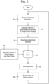
- Any symbols required to be displayed at fixed positions within the image area of the display may be positioned and drawn at STEP 30 and the resultant data set stored in the image store 25.
- the contents of the image store 25 are output and used to generate video data, combining the determined pixel characteristics defined at STEP 20 with those defined at STEP 30.
- the generated video data are then output to a display device of the display system to generate the image for the image refresh period such that, at STEP 40, it appears on the display visible to the viewer.
- the process then resumes at STEP 10 for the next image refresh period.
- the matrix [ HW] defines a transformation of a known line of sight vector P W to a point in inertial space into a line of sight vector P H to the point in a frame of reference of the HMD.
- the calculated positions are used to draw the respective light components of the symbol such that each light component appears in the display to be aligned to the direction of its respective adjusted direction P' H or, in the case of the light component in the selected reference phase, unadjusted direction P H .
- the light components of the symbol therefore appear in the display to be aligned during that relative movement of the display and the assumed fixed direction of gaze of the user.
- the rate data are synchronised to the expected time of displaying at least one of the light components, for example those during the selected reference phase, then it may be expected that the light components will appear more accurately aligned in the display, in particular where the rate of relative movement happens to be changing rapidly at that time.
- head rotations comprise only horizontal and vertical components, given the design of pilot helmets and the confines of an aircraft cockpit.
- roll rate r x is assumed to be zero.
- Such a simplification provides an opportunity to adopt a simpler displacement method for determining an adjusted position in the display for space-stabilised symbols rather than the rotational adjustment method described above.
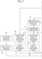
- the determined rate from STEP 55 is used, together with predetermined information read from a STORE 65 giving the relative timing of light components in the first phase relative to those in the second phase, to determine a rotational adjustment to the HMD orientation, for example a rotation matrix [H'H] as described above, applicable to the first phase components of space-stabilised symbols to be displayed.
- the determined rate from STEP 55 is used, together with predetermined information read from a STORE 65 giving the relative timing of light components in the third phase relative to those of the second phase, to determine a rotational adjustment applicable to the third phase components of space-stabilised symbols to be displayed.
- the determined rotational adjustments [H'H] are applied at STEP 75 and STEP 80 to the HMD orientation [HW] determined at STEP 50 for the first and third phase components, respectively.
- the adjusted HMD orientation determined at STEP 75 for the first phase components is then used at STEP 85, together with already determined data defining a known direction to a point in inertial space, read from a STORE 90, to which a space stabilised symbol is to be aligned, to calculate a position on the HMD image area for displaying the first phase component of the symbol.
- the adjusted HMD orientation determined at STEP 80 for the third phase components is used, together with the already determined data defining the direction to the feature in inertial space, read from a STORE 90, to calculate a position on the HMD image area for displaying the third phase component of the symbol.
- the HMD orientation determined at STEP 50 is used at STEP 100 to calculate a position for displaying the 'reference' second phase light component of the space-stabilised symbol.
- the positions determined at STEP 85, STEP 95 and STEP 100 are then used at STEP 105, STEP 110 and STEP 115 respectively to draw the first, third and second phase components of the symbol, as in STEP 20 of the known process shown in Figure 2 .
- the data defining the characteristics of pixels involved in displaying the space-stabilised symbol are stored in an image STORE 120.
- the position of any symbols to be drawn at a fixed position in the image area of the HMD is calculated at STEP 125 and the light components of the fixed symbols are drawn at STEP 130.
- the resultant data are stored in the image STORE 120.
- the results of applying the above techniques to determine the display positions for the three phases of light components can be seen for an example rate of relative movement.
- the determined position of each of the pulses of the first and third phase light components intended for Pixel 2 of a space-stabilised symbol can be seen to be displaced to the right (150) and to the left (155), respectively, of the second 'reference' phase light component, as compared with the positioning shown in Figure 1a where there is substantially no relative movement. It can be seen in Figure 4a that the position of the selected 'reference' second phase light component on the display is not changed in comparison to its indicated position in Figure 1a by the present invention.
- the first and third light components will be displaced according to the rotational correction determined at STEP 60 and STEP 70, respectively, resulting in a two-dimensional vector displacement of those components across the image area of the HMD unless, as in this illustrated example, the direction of relative movement of the HMD and eye gaze direction is substantially in azimuth.
- Example embodiments of the present invention may be implemented in any head or helmet-based digital display system with access to tracker data giving an indication of eye movement relative to the display.
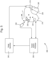
- An example helmet-mounted display system in which embodiments of the present invention may be implemented will now be described in outline with reference to Figure 5 .
- the tracker system may include one or more inertial sensors 225 mounted upon the helmet 210, arranged to supply data to a Tracker System Processor 230.
- the tracker system may also include an optical helmet tracker comprising an arrangement of light-emitting diodes (LEDs) 235 integrated within the shell of the helmet 210 and controllable by the Tracker System Processor 230 to emit pulses of light.
- the optical helmet tracker also includes an arrangement of one or more cameras 240 (one of which is shown in Figure 5 ) at known fixed positions arranged to detect light from the helmet-mounted LEDs 235 and to send corresponding signals to the Tracker System Processor 230.
- the Tracker System Processor 230 is arranged to interpret the data received from the inertial sensors 225 and from the cameras 240 of the optical helmet tracker system to determine orientation of the helmet 210 and hence of the display 215 in inertial space or relative to an aircraft for example (not shown in Figure 5 ) in which the pilot 205 may be travelling.
- the Tracker System Processor 230 may also determine a rate of change in orientation of the helmet and hence of the display 215 from those data inputs and output display orientation and rate of change data to an Image Generator 245.
- the Image Generator 245 is arranged to generate images, including space-stabilised images for display to the pilot viewing the helmet-mounted display 215 such that they appear overlain on the pilot's view through the transparent waveguide 215 of the outside world.
- the Image Generator 245 may be arranged to implement the techniques described above for taking account of detected movement of the pilot's eye 220 or direction of gaze relative to the image area of the helmet-mounted display 215, using data from the Tracker System Processor 230, when positioning different light components of space-stabilised symbols with the aim of reducing the perceived incidence of image smearing or multiple image effects during movement of the eye 220 or the pilot's direction of gaze relative to the image area of the display 215.
Landscapes
- Engineering & Computer Science (AREA)
- Physics & Mathematics (AREA)
- General Physics & Mathematics (AREA)
- Theoretical Computer Science (AREA)
- General Engineering & Computer Science (AREA)
- Computer Hardware Design (AREA)
- Optics & Photonics (AREA)
- Human Computer Interaction (AREA)
- Multimedia (AREA)
- Signal Processing (AREA)
- Control Of Indicators Other Than Cathode Ray Tubes (AREA)
- Controls And Circuits For Display Device (AREA)
Applications Claiming Priority (3)
| Application Number | Priority Date | Filing Date | Title |
|---|---|---|---|
| GBGB1518113.4A GB201518113D0 (en) | 2015-10-13 | 2015-10-13 | Improvements in and relating to displays |
| EP16777785.3A EP3363011B1 (de) | 2015-10-13 | 2016-10-03 | Verbesserungen an und im zusammenhang mit anzeigen |
| PCT/GB2016/053069 WO2017064469A1 (en) | 2015-10-13 | 2016-10-03 | Improvements in and relating to displays |
Related Parent Applications (2)
| Application Number | Title | Priority Date | Filing Date |
|---|---|---|---|
| EP16777785.3A Division EP3363011B1 (de) | 2015-10-13 | 2016-10-03 | Verbesserungen an und im zusammenhang mit anzeigen |
| EP16777785.3A Division-Into EP3363011B1 (de) | 2015-10-13 | 2016-10-03 | Verbesserungen an und im zusammenhang mit anzeigen |
Publications (2)
| Publication Number | Publication Date |
|---|---|
| EP4296829A2 true EP4296829A2 (de) | 2023-12-27 |
| EP4296829A3 EP4296829A3 (de) | 2024-01-10 |
Family
ID=55130988
Family Applications (2)
| Application Number | Title | Priority Date | Filing Date |
|---|---|---|---|
| EP16777785.3A Active EP3363011B1 (de) | 2015-10-13 | 2016-10-03 | Verbesserungen an und im zusammenhang mit anzeigen |
| EP23208742.9A Pending EP4296829A3 (de) | 2015-10-13 | 2016-10-03 | Verbesserungen an und im zusammenhang mit anzeigen |
Family Applications Before (1)
| Application Number | Title | Priority Date | Filing Date |
|---|---|---|---|
| EP16777785.3A Active EP3363011B1 (de) | 2015-10-13 | 2016-10-03 | Verbesserungen an und im zusammenhang mit anzeigen |
Country Status (7)
| Country | Link |
|---|---|
| US (1) | US10473937B2 (de) |
| EP (2) | EP3363011B1 (de) |
| KR (1) | KR102600906B1 (de) |
| AU (2) | AU2016337278A1 (de) |
| ES (1) | ES2973125T3 (de) |
| GB (2) | GB201518113D0 (de) |
| WO (1) | WO2017064469A1 (de) |
Families Citing this family (6)
| Publication number | Priority date | Publication date | Assignee | Title |
|---|---|---|---|---|
| GB201518110D0 (en) | 2015-10-13 | 2015-11-25 | Bae Systems Plc | Improvements in and relating to displays |
| GB201518112D0 (en) | 2015-10-13 | 2015-11-25 | Bae Systems Plc | Improvements in and relating to displays |
| GB201518113D0 (en) | 2015-10-13 | 2015-11-25 | Bae Systems Plc | Improvements in and relating to displays |
| WO2019012522A1 (en) * | 2017-07-11 | 2019-01-17 | Elbit Systems Ltd. | SYSTEM AND METHOD FOR CORRECTING A RUNNING DISPLAY EFFECT |
| IL253432A0 (en) | 2017-07-11 | 2017-09-28 | Elbit Systems Ltd | System and method for correcting a rolling display effect |
| US11528953B2 (en) * | 2020-05-19 | 2022-12-20 | Rockwell Collins, Inc. | Display embedded visor helmet mounted display |
Family Cites Families (16)
| Publication number | Priority date | Publication date | Assignee | Title |
|---|---|---|---|---|
| US5764202A (en) | 1995-06-26 | 1998-06-09 | Cae Electronics Ltd. | Suppressing image breakup in helmut mounted displays which use temporally separated bit planes to achieve grey scale |
| WO2004073315A1 (en) * | 2003-02-14 | 2004-08-26 | Koninklijke Philips Electronics N.V. | Processing signals for a color sequential display |
| US7593026B2 (en) | 2005-05-11 | 2009-09-22 | L-3 Communications Corporation | Dynamic display optimization method and system with image motion |
| US9389419B2 (en) | 2008-08-14 | 2016-07-12 | Honeywell International Inc. | Near-to-eye display artifact reduction system and method |
| JP5353361B2 (ja) * | 2009-03-26 | 2013-11-27 | ブラザー工業株式会社 | カラー画像表示装置 |
| WO2011018655A2 (en) | 2009-08-13 | 2011-02-17 | Bae Systems Plc | Head up display system |
| US20140247286A1 (en) | 2012-02-20 | 2014-09-04 | Google Inc. | Active Stabilization for Heads-Up Displays |
| US8970495B1 (en) * | 2012-03-09 | 2015-03-03 | Google Inc. | Image stabilization for color-sequential displays |
| US20140176591A1 (en) * | 2012-12-26 | 2014-06-26 | Georg Klein | Low-latency fusing of color image data |
| US9407797B1 (en) | 2013-04-17 | 2016-08-02 | Valve Corporation | Methods and systems for changing duty cycle to reduce judder effect |
| US10262462B2 (en) * | 2014-04-18 | 2019-04-16 | Magic Leap, Inc. | Systems and methods for augmented and virtual reality |
| US9230473B2 (en) | 2013-06-24 | 2016-01-05 | Microsoft Technology Licensing, Llc | Dual duty cycle OLED to enable dynamic control for reduced motion blur control with constant brightness in augmented reality experiences |
| EP3114525A4 (de) | 2014-03-03 | 2018-03-07 | Eyeway Vision Ltd. | Augenprojektionssystem |
| GB201518112D0 (en) | 2015-10-13 | 2015-11-25 | Bae Systems Plc | Improvements in and relating to displays |
| GB201518110D0 (en) | 2015-10-13 | 2015-11-25 | Bae Systems Plc | Improvements in and relating to displays |
| GB201518113D0 (en) | 2015-10-13 | 2015-11-25 | Bae Systems Plc | Improvements in and relating to displays |
-
2015
- 2015-10-13 GB GBGB1518113.4A patent/GB201518113D0/en not_active Ceased
-
2016
- 2016-10-03 US US15/767,222 patent/US10473937B2/en active Active
- 2016-10-03 KR KR1020187013445A patent/KR102600906B1/ko active Active
- 2016-10-03 WO PCT/GB2016/053069 patent/WO2017064469A1/en not_active Ceased
- 2016-10-03 GB GB1616786.8A patent/GB2543948B/en active Active
- 2016-10-03 EP EP16777785.3A patent/EP3363011B1/de active Active
- 2016-10-03 ES ES16777785T patent/ES2973125T3/es active Active
- 2016-10-03 AU AU2016337278A patent/AU2016337278A1/en not_active Abandoned
- 2016-10-03 EP EP23208742.9A patent/EP4296829A3/de active Pending
-
2022
- 2022-07-21 AU AU2022206781A patent/AU2022206781B2/en active Active
Also Published As
| Publication number | Publication date |
|---|---|
| KR20180066212A (ko) | 2018-06-18 |
| GB2543948B (en) | 2020-05-20 |
| GB201616786D0 (en) | 2016-11-16 |
| AU2022206781A1 (en) | 2022-08-18 |
| GB201518113D0 (en) | 2015-11-25 |
| EP4296829A3 (de) | 2024-01-10 |
| EP3363011A1 (de) | 2018-08-22 |
| WO2017064469A1 (en) | 2017-04-20 |
| AU2022206781B2 (en) | 2024-06-13 |
| AU2016337278A1 (en) | 2018-04-26 |
| KR102600906B1 (ko) | 2023-11-09 |
| ES2973125T3 (es) | 2024-06-18 |
| US10473937B2 (en) | 2019-11-12 |
| EP3363011B1 (de) | 2023-12-20 |
| GB2543948A (en) | 2017-05-03 |
| US20190072768A1 (en) | 2019-03-07 |
Similar Documents
| Publication | Publication Date | Title |
|---|---|---|
| US10504399B2 (en) | In and relating to displays | |
| AU2022206781B2 (en) | Improvements in and relating to displays | |
| US10670880B2 (en) | Image display apparatus and image display method | |
| JP2010250061A5 (de) | ||
| US20120019568A1 (en) | Image display apparatus, image display method, and image supply apparatus | |
| JP2012028963A5 (de) | ||
| JP6571767B2 (ja) | 映像表示装置および制御方法 | |
| KR102580633B1 (ko) | 디스플레이에 있어서 그리고 디스플레이에 관한 개선 | |
| CN108307185A (zh) | 裸眼3d显示设备及其显示方法 | |
| US20180309968A1 (en) | Projector, video display device, and video display method | |
| JP5370174B2 (ja) | 映像信号処理装置、映像信号処理方法および映像表示装置 | |
| US12537929B2 (en) | Display device and display method | |
| CN108717234A (zh) | 视力保护方法和显示装置 | |
| JP2020013135A (ja) | 映像表示装置および制御方法 |
Legal Events
| Date | Code | Title | Description |
|---|---|---|---|
| PUAI | Public reference made under article 153(3) epc to a published international application that has entered the european phase |
Free format text: ORIGINAL CODE: 0009012 |
|
| STAA | Information on the status of an ep patent application or granted ep patent |
Free format text: STATUS: REQUEST FOR EXAMINATION WAS MADE |
|
| REG | Reference to a national code |
Ref country code: DE Ref legal event code: R079 Free format text: PREVIOUS MAIN CLASS: G06F0003010000 Ipc: G09G0003000000 |
|
| PUAL | Search report despatched |
Free format text: ORIGINAL CODE: 0009013 |
|
| 17P | Request for examination filed |
Effective date: 20231109 |
|
| AC | Divisional application: reference to earlier application |
Ref document number: 3363011 Country of ref document: EP Kind code of ref document: P |
|
| AK | Designated contracting states |
Kind code of ref document: A2 Designated state(s): AL AT BE BG CH CY CZ DE DK EE ES FI FR GB GR HR HU IE IS IT LI LT LU LV MC MK MT NL NO PL PT RO RS SE SI SK SM TR |
|
| AK | Designated contracting states |
Kind code of ref document: A3 Designated state(s): AL AT BE BG CH CY CZ DE DK EE ES FI FR GB GR HR HU IE IS IT LI LT LU LV MC MK MT NL NO PL PT RO RS SE SI SK SM TR |
|
| RIC1 | Information provided on ipc code assigned before grant |
Ipc: G06F 3/01 20060101ALN20231204BHEP Ipc: G02B 27/01 20060101ALN20231204BHEP Ipc: G09G 3/20 20060101ALI20231204BHEP Ipc: G09G 3/00 20060101AFI20231204BHEP |
|
| RIN1 | Information on inventor provided before grant (corrected) |
Inventor name: TRYTHALL, SIMON |
|
| STAA | Information on the status of an ep patent application or granted ep patent |
Free format text: STATUS: EXAMINATION IS IN PROGRESS |
|
| 17Q | First examination report despatched |
Effective date: 20251017 |