EP4296801A1 - Verfahren zur anzeige eines steuerfensters einer zweiten elektronischen vorrichtung und erste elektronische vorrichtung - Google Patents
Verfahren zur anzeige eines steuerfensters einer zweiten elektronischen vorrichtung und erste elektronische vorrichtung Download PDFInfo
- Publication number
- EP4296801A1 EP4296801A1 EP22778968.2A EP22778968A EP4296801A1 EP 4296801 A1 EP4296801 A1 EP 4296801A1 EP 22778968 A EP22778968 A EP 22778968A EP 4296801 A1 EP4296801 A1 EP 4296801A1
- Authority
- EP
- European Patent Office
- Prior art keywords
- electronic device
- ultra
- base station
- wideband
- coordinates
- Prior art date
- Legal status (The legal status is an assumption and is not a legal conclusion. Google has not performed a legal analysis and makes no representation as to the accuracy of the status listed.)
- Pending
Links
Images


Classifications
-
- H—ELECTRICITY
- H04—ELECTRIC COMMUNICATION TECHNIQUE
- H04N—PICTORIAL COMMUNICATION, e.g. TELEVISION
- H04N21/00—Selective content distribution, e.g. interactive television or video on demand [VOD]
- H04N21/40—Client devices specifically adapted for the reception of or interaction with content, e.g. set-top-box [STB]; Operations thereof
- H04N21/41—Structure of client; Structure of client peripherals
- H04N21/422—Input-only peripherals, i.e. input devices connected to specially adapted client devices, e.g. global positioning system [GPS]
- H04N21/42204—User interfaces specially adapted for controlling a client device through a remote control device; Remote control devices therefor
- H04N21/42206—User interfaces specially adapted for controlling a client device through a remote control device; Remote control devices therefor characterized by hardware details
- H04N21/4222—Remote control device emulator integrated into a non-television apparatus, e.g. a PDA, media center or smart toy
-
- G—PHYSICS
- G06—COMPUTING OR CALCULATING; COUNTING
- G06F—ELECTRIC DIGITAL DATA PROCESSING
- G06F3/00—Input arrangements for transferring data to be processed into a form capable of being handled by the computer; Output arrangements for transferring data from processing unit to output unit, e.g. interface arrangements
- G06F3/01—Input arrangements or combined input and output arrangements for interaction between user and computer
- G06F3/048—Interaction techniques based on graphical user interfaces [GUI]
- G06F3/0481—Interaction techniques based on graphical user interfaces [GUI] based on specific properties of the displayed interaction object or a metaphor-based environment, e.g. interaction with desktop elements like windows or icons, or assisted by a cursor's changing behaviour or appearance
- G06F3/04812—Interaction techniques based on cursor appearance or behaviour, e.g. being affected by the presence of displayed objects
-
- G—PHYSICS
- G06—COMPUTING OR CALCULATING; COUNTING
- G06F—ELECTRIC DIGITAL DATA PROCESSING
- G06F3/00—Input arrangements for transferring data to be processed into a form capable of being handled by the computer; Output arrangements for transferring data from processing unit to output unit, e.g. interface arrangements
- G06F3/01—Input arrangements or combined input and output arrangements for interaction between user and computer
- G06F3/048—Interaction techniques based on graphical user interfaces [GUI]
- G06F3/0484—Interaction techniques based on graphical user interfaces [GUI] for the control of specific functions or operations, e.g. selecting or manipulating an object, an image or a displayed text element, setting a parameter value or selecting a range
- G06F3/04847—Interaction techniques to control parameter settings, e.g. interaction with sliders or dials
-
- H—ELECTRICITY
- H04—ELECTRIC COMMUNICATION TECHNIQUE
- H04N—PICTORIAL COMMUNICATION, e.g. TELEVISION
- H04N21/00—Selective content distribution, e.g. interactive television or video on demand [VOD]
- H04N21/40—Client devices specifically adapted for the reception of or interaction with content, e.g. set-top-box [STB]; Operations thereof
- H04N21/41—Structure of client; Structure of client peripherals
- H04N21/4104—Peripherals receiving signals from specially adapted client devices
- H04N21/4126—The peripheral being portable, e.g. PDAs or mobile phones
- H04N21/41265—The peripheral being portable, e.g. PDAs or mobile phones having a remote control device for bidirectional communication between the remote control device and client device
-
- H—ELECTRICITY
- H04—ELECTRIC COMMUNICATION TECHNIQUE
- H04N—PICTORIAL COMMUNICATION, e.g. TELEVISION
- H04N21/00—Selective content distribution, e.g. interactive television or video on demand [VOD]
- H04N21/40—Client devices specifically adapted for the reception of or interaction with content, e.g. set-top-box [STB]; Operations thereof
- H04N21/41—Structure of client; Structure of client peripherals
- H04N21/422—Input-only peripherals, i.e. input devices connected to specially adapted client devices, e.g. global positioning system [GPS]
- H04N21/42204—User interfaces specially adapted for controlling a client device through a remote control device; Remote control devices therefor
- H04N21/42206—User interfaces specially adapted for controlling a client device through a remote control device; Remote control devices therefor characterized by hardware details
- H04N21/42208—Display device provided on the remote control
-
- H—ELECTRICITY
- H04—ELECTRIC COMMUNICATION TECHNIQUE
- H04N—PICTORIAL COMMUNICATION, e.g. TELEVISION
- H04N21/00—Selective content distribution, e.g. interactive television or video on demand [VOD]
- H04N21/40—Client devices specifically adapted for the reception of or interaction with content, e.g. set-top-box [STB]; Operations thereof
- H04N21/41—Structure of client; Structure of client peripherals
- H04N21/422—Input-only peripherals, i.e. input devices connected to specially adapted client devices, e.g. global positioning system [GPS]
- H04N21/42204—User interfaces specially adapted for controlling a client device through a remote control device; Remote control devices therefor
- H04N21/42206—User interfaces specially adapted for controlling a client device through a remote control device; Remote control devices therefor characterized by hardware details
- H04N21/42221—Transmission circuitry, e.g. infrared [IR] or radio frequency [RF]
-
- H—ELECTRICITY
- H04—ELECTRIC COMMUNICATION TECHNIQUE
- H04N—PICTORIAL COMMUNICATION, e.g. TELEVISION
- H04N21/00—Selective content distribution, e.g. interactive television or video on demand [VOD]
- H04N21/40—Client devices specifically adapted for the reception of or interaction with content, e.g. set-top-box [STB]; Operations thereof
- H04N21/41—Structure of client; Structure of client peripherals
- H04N21/422—Input-only peripherals, i.e. input devices connected to specially adapted client devices, e.g. global positioning system [GPS]
- H04N21/42204—User interfaces specially adapted for controlling a client device through a remote control device; Remote control devices therefor
- H04N21/42206—User interfaces specially adapted for controlling a client device through a remote control device; Remote control devices therefor characterized by hardware details
- H04N21/42222—Additional components integrated in the remote control device, e.g. timer, speaker, sensors for detecting position, direction or movement of the remote control, microphone or battery charging device
-
- H—ELECTRICITY
- H04—ELECTRIC COMMUNICATION TECHNIQUE
- H04N—PICTORIAL COMMUNICATION, e.g. TELEVISION
- H04N21/00—Selective content distribution, e.g. interactive television or video on demand [VOD]
- H04N21/40—Client devices specifically adapted for the reception of or interaction with content, e.g. set-top-box [STB]; Operations thereof
- H04N21/43—Processing of content or additional data, e.g. demultiplexing additional data from a digital video stream; Elementary client operations, e.g. monitoring of home network or synchronising decoder's clock; Client middleware
- H04N21/431—Generation of visual interfaces for content selection or interaction; Content or additional data rendering
- H04N21/4312—Generation of visual interfaces for content selection or interaction; Content or additional data rendering involving specific graphical features, e.g. screen layout, special fonts or colors, blinking icons, highlights or animations
-
- H—ELECTRICITY
- H04—ELECTRIC COMMUNICATION TECHNIQUE
- H04N—PICTORIAL COMMUNICATION, e.g. TELEVISION
- H04N21/00—Selective content distribution, e.g. interactive television or video on demand [VOD]
- H04N21/40—Client devices specifically adapted for the reception of or interaction with content, e.g. set-top-box [STB]; Operations thereof
- H04N21/43—Processing of content or additional data, e.g. demultiplexing additional data from a digital video stream; Elementary client operations, e.g. monitoring of home network or synchronising decoder's clock; Client middleware
- H04N21/442—Monitoring of processes or resources, e.g. detecting the failure of a recording device, monitoring the downstream bandwidth, the number of times a movie has been viewed, the storage space available from the internal hard disk
- H04N21/44227—Monitoring of local network, e.g. connection or bandwidth variations; Detecting new devices in the local network
-
- H—ELECTRICITY
- H04—ELECTRIC COMMUNICATION TECHNIQUE
- H04W—WIRELESS COMMUNICATION NETWORKS
- H04W4/00—Services specially adapted for wireless communication networks; Facilities therefor
- H04W4/02—Services making use of location information
- H04W4/023—Services making use of location information using mutual or relative location information between multiple location based services [LBS] targets or of distance thresholds
-
- H—ELECTRICITY
- H04—ELECTRIC COMMUNICATION TECHNIQUE
- H04W—WIRELESS COMMUNICATION NETWORKS
- H04W4/00—Services specially adapted for wireless communication networks; Facilities therefor
- H04W4/80—Services using short range communication, e.g. near-field communication [NFC], radio-frequency identification [RFID] or low energy communication
-
- H—ELECTRICITY
- H04—ELECTRIC COMMUNICATION TECHNIQUE
- H04W—WIRELESS COMMUNICATION NETWORKS
- H04W4/00—Services specially adapted for wireless communication networks; Facilities therefor
- H04W4/30—Services specially adapted for particular environments, situations or purposes
- H04W4/33—Services specially adapted for particular environments, situations or purposes for indoor environments, e.g. buildings
-
- H—ELECTRICITY
- H04—ELECTRIC COMMUNICATION TECHNIQUE
- H04W—WIRELESS COMMUNICATION NETWORKS
- H04W4/00—Services specially adapted for wireless communication networks; Facilities therefor
- H04W4/30—Services specially adapted for particular environments, situations or purposes
- H04W4/38—Services specially adapted for particular environments, situations or purposes for collecting sensor information
-
- H—ELECTRICITY
- H04—ELECTRIC COMMUNICATION TECHNIQUE
- H04W—WIRELESS COMMUNICATION NETWORKS
- H04W88/00—Devices specially adapted for wireless communication networks, e.g. terminals, base stations or access point devices
- H04W88/02—Terminal devices
-
- H—ELECTRICITY
- H04—ELECTRIC COMMUNICATION TECHNIQUE
- H04W—WIRELESS COMMUNICATION NETWORKS
- H04W88/00—Devices specially adapted for wireless communication networks, e.g. terminals, base stations or access point devices
- H04W88/08—Access point devices
Definitions
- This application relates to the terminal field, and in particular, to a first electronic device and a method for displaying a control window of a second electronic device.
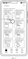
- a second electronic device is controlled by using an application (application, APP) installed on a first electronic device, so that control functions of different second electronic devices (for example, a remote control function of a smart television in a living room, a remote control function of a smart television in a bedroom, and a remote control function of a cabinet-type smart air conditioner in a living room) may be integrated into one first electronic device.
- control functions of different second electronic devices for example, a remote control function of a smart television in a living room, a remote control function of a smart television in a bedroom, and a remote control function of a cabinet-type smart air conditioner in a living room
- the first electronic device has a remote control function of the second electronic device, and may remotely control the second electronic device. In this way, after a first electronic device of a user points to a second electronic device, a control window of the second electronic device may be displayed. This facilitates a user operation and reduces time consumption.
- a circuit or a module for implementing precise positioning needs to be configured for the second electronic device, causing excessively high costs of the second electronic device.
- the foregoing circuit or module is configured for all second electronic devices, for example, at home or in an office, causing a significant increase in costs.
- a common family or a common company may be unwilling to upgrade all second electronic devices or perform replacement in all second electronic devices due to cost considerations.
- a first electronic device may point to a second electronic device from the back of the second electronic device.
- a control window of the second electronic device is also displayed, but the user originally does not want to control the second electronic device. As a result, inconvenience is brought to the user.
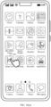
- this application provides a first electronic device and a method for displaying a control window of a second electronic device. Even if none of second electronic devices is upgraded or replaced, the technical solutions provided in this application can enable a first electronic device of a user to point to a second electronic device that is not configured with the foregoing circuit or module. Moreover, a second electronic device can be located after the first electronic device is located in a front area of the second electronic device and points to the second electronic device, to quickly display a control window of the second electronic device. This facilitates user control, saves time, and improves user experience.
- a cursor corresponding to the first electronic device can be further displayed on the display screen of the second electronic device, so that a user can control the second electronic device by using the first electronic device more conveniently, and user experience is better.
- a first electronic device of a user after pointing to a second electronic device that is not upgraded, a first electronic device of a user can locate the second electronic device in a low-cost manner, to quickly display (for example, pop up and display) a control window of the second electronic device. After the first electronic device displays the control window of the second electronic device, the user can control the second electronic device based on the control window.
- a cursor corresponding to the first electronic device can be further displayed on the display screen of the second electronic device, so that the user can control the second electronic device by using the first electronic device more conveniently, and user experience is better.
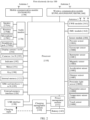
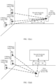
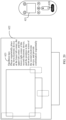
- a first electronic device includes an ultra-wideband module and an inertia measurement unit module.
- the first electronic device communicates with a first ultra-wideband base station (a UWB base station) through ultra-wideband wireless communication.
- the first electronic device obtains, through the ultra-wideband wireless communication, coordinates of the first electronic device that are based on the first ultra-wideband base station.
- the first electronic device further includes a processor, a memory, and a computer program.
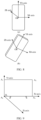
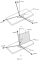
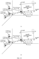
- a position and an orientation of the second electronic device in space may be determined based on location marking performed by the first electronic device on the second electronic device four times, to determine whether the first electronic device is located in the front area of the second electronic device and points to the second electronic device.
- the technical solutions provided in this application can enable a first electronic device of a user to point to a second electronic device that is not configured with the foregoing circuit or module.
- a second electronic device can be located after the first electronic device is located in a front area of the second electronic device and points to the second electronic device, to quickly display a control window of the second electronic device.
- the first electronic device before the first electronic device performs the foregoing operations, the first electronic device cannot obtain position information of the second electronic device.
- an edge contour of a housing of the second electronic device or the edge contour of the display area of the second electronic device can be determined based on the first vertex angle position, the second vertex angle position, and the third vertex angle position. Therefore, when a circuit or module for implementing precise positioning is upgraded or replaced for none of second electronic devices, a first electronic device of a user is enabled to point to a second electronic device that is not configured with the foregoing circuit or module. Moreover, a second electronic device can be located after the first electronic device is located in a front area of the second electronic device and points to the second electronic device, to quickly display a control window of the second electronic device. This facilitates user control, saves time, and improves user experience.
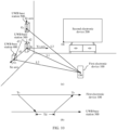
- the first ultra-wideband base station includes three antennas, and communicates with the first electronic device by using the three antennas through the ultra-wideband wireless communication. In this way, the foregoing technical effect can be achieved by using only one UWB base station.
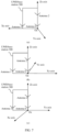
- the first coordinate system is calibrated first, so that subsequent marking of coordinates in the first coordinate system is more accurate.
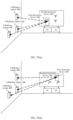
- the second ultra-wideband base station and the third ultra-wideband base station are installed on a same plane as the first ultra-wideband base station. In this way, in a case of at least three UWB base stations, a preferred installation manner of three or more UWB base stations is provided.
- the second ultra-wideband base station needs to be installed in a first direction of the first ultra-wideband base station, and/or the third ultra-wideband base station needs to be installed in a second direction of the first ultra-wideband base station.
- an installation requirement is provided. In this way, during use, a consumer may perform installation based on the requirement, thereby facilitating use of a desired first coordinate system in a subsequent step.
- the first electronic device communicates with the second electronic device through another wireless communication, where the another wireless communication is different from the ultra-wideband wireless communication; and the second electronic device does not include an ultra-wideband module, or the second electronic device includes an ultra-wideband module but the ultra-wideband module is unavailable.
- the first electronic device obtains, through the ultra-wideband wireless communication, coordinates of the first electronic device that are based on the first ultra-wideband base station includes: The first electronic device obtains, in real time or periodically through the ultra-wideband wireless communication, the coordinates of the first electronic device that are based on the first ultra-wideband base station.
- the first electronic device obtains, based on the fifth coordinates, coordinate values of the fifth position in a third coordinate system, and determines, based on the coordinate values of the fifth position in the third coordinate system, whether the first electronic device is located in the front area of the second electronic device, where the third coordinate system is a coordinate system established by the second electronic device, or the third coordinate system is a coordinate system preset on the second electronic device; and the first electronic device determines, depending on whether a falling point, on the second electronic device, of a straight line on which the pointing direction of the first electronic device is located is within an area formed by the edge contour of the second electronic device, whether the first electronic device points to the second electronic device; or the first electronic device determines, depending on whether a falling point, on the second electronic device, of a straight line on which the pointing direction of the first electronic device is located is within an area formed by the edge contour of the display area of the second electronic device, whether the first electronic device points to the second
- the first electronic device obtains, based on the fifth coordinates, a component of coordinate values of the fifth position in a third coordinate system on a coordinate axis of the third coordinate system, and determines, based on the coordinate values of the fifth position in the third coordinate system, whether the first electronic device is located in the front area of the second electronic device, where the third coordinate system is a coordinate system established by the second electronic device, or the third coordinate system is a coordinate system preset on the second electronic device; and the first electronic device determines, depending on whether a falling point, on the second electronic device, of a straight line on which the pointing direction of the first electronic device is located is within an area formed by the edge contour of the second electronic device, whether the first electronic device points to the second electronic device; or the first electronic device determines, depending on whether a falling point, on the second electronic device, of a straight line on which the pointing direction of the first electronic device is located is within an area formed by the edge contour of the display
- a first electronic device includes an ultra-wideband module and an inertia measurement unit module.
- the first electronic device communicates with a first ultra-wideband base station through ultra-wideband wireless communication.
- the first electronic device communicates with a second electronic device through another wireless communication, where the another wireless communication is different from the ultra-wideband wireless communication.
- the first electronic device obtains, through the ultra-wideband wireless communication, coordinates of the first electronic device that are based on the first ultra-wideband base station.
- the first electronic device obtains a length and a width of an edge contour of the second electronic device or a length and a width of an edge contour of a display area of the second electronic device through the another wireless communication.
- the first electronic device further includes a processor, a memory, and a computer program.
- the computer program is stored in the memory; and when the computer program is executed by the processor, the first electronic device is enabled to perform the following operations: in response to a first input received when the first electronic device moves to a vertex angle position of the second electronic device and an orientation of the first electronic device is the same as an orientation of the second electronic device, recording first coordinates of the first electronic device that are based on the first ultra-wideband base station as coordinates of the vertex angle position, and recording the orientation of the first electronic device as the orientation of the second electronic device; and displaying, by the first electronic device, a control window of the second electronic device in response to detecting that the first electronic device is located in the front area of the second electronic device and points to the second electronic device, where a detection result that the first electronic device is located in the front area of the second electronic device and points to the second electronic device is associated with the vertex angle position and the orientation of the second electronic device.
- a cursor corresponding to the first electronic device can be further displayed on the display screen of the second electronic device, so that a user can control the second electronic device by using the first electronic device more conveniently, and user experience is better.
- the vertex angle position is a vertex angle position on the edge contour of the second electronic device; or the vertex angle position is a vertex angle position on the edge contour of the display area of the second electronic device.
- the displaying, by the first electronic device, a control window of the second electronic device in response to detecting that the first electronic device is located in the front area of the second electronic device and points to the second electronic device includes: in response to detecting that the first electronic device is located at a second position outside the second electronic device, obtaining, by the first electronic device, second coordinates of the first electronic device that are based on the first ultra-wideband base station, and determining, by the first electronic device based on the first coordinates, the length of the edge contour of the second electronic device, the width of the edge contour of the second electronic device, the second coordinates, the orientation of the second electronic device, and a pointing direction of the first electronic device, whether the first electronic device is located in the front area of the second electronic device and whether the first electronic device points to the second electronic device; or in response to detecting that the first electronic device is located at a second position outside the second electronic device, obtaining, by the first electronic device, second coordinates of the first electronic
- the first electronic device obtains, based on the second coordinates, coordinate values of the second position in a third coordinate system, and determines, based on the coordinate values of the second position in the third coordinate system, whether the first electronic device is located in the front area of the second electronic device, where the third coordinate system is a coordinate system established by the second electronic device, or the third coordinate system is a coordinate system preset on the second electronic device; and the first electronic device determines, depending on whether a falling point, on the second electronic device, of a straight line on which the pointing direction of the first electronic device is located is within an area formed by the edge contour of the second electronic device, whether the first electronic device points to the second electronic device; or the first electronic device determines, depending on whether a falling point, on the second electronic device, of a straight line on which the pointing direction of the first electronic device is located is within an area formed by the edge contour of the display area of the second electronic device, whether the first electronic device points to the second
- the first electronic device before the first electronic device performs the foregoing operations, the first electronic device cannot obtain position information of the second electronic device.
- the first electronic device before the first electronic device performs the foregoing operations, the first electronic device cannot obtain orientation information of the second electronic device.
- the first electronic device when the first electronic device does not point to the second electronic device, the first electronic device does not display the control window of the second electronic device.
- the coordinates of the first electronic device that are based on the first ultra-wideband base station include: coordinates of the first electronic device that are based on a first coordinate system of the first ultra-wideband base station, where the first coordinate system is a coordinate system established by the first ultra-wideband base station, or the first coordinate system is a coordinate system preset on the first ultra-wideband base station; and before responding to the first input received when the first electronic device is located at the first vertex angle position of the second electronic device, the first electronic device further performs calibration relative to the first coordinate system.
- the second ultra-wideband base station and the third ultra-wideband base station are installed on a same plane as the first ultra-wideband base station.
- the first electronic device communicates with the second electronic device through another wireless communication, where the another wireless communication is different from the ultra-wideband wireless communication; and the second electronic device does not include an ultra-wideband module, or the second electronic device includes an ultra-wideband module but the ultra-wideband module is unavailable.
- the first electronic device obtains, through the ultra-wideband wireless communication, coordinates of the first electronic device that are based on the first ultra-wideband base station includes: The first electronic device obtains, in real time or periodically through the ultra-wideband wireless communication, the coordinates of the first electronic device that are based on the first ultra-wideband base station.
- the straight line on which the pointing direction of the first electronic device is located is obtained based on the inertia measurement unit module.
- a first electronic device includes an ultra-wideband module and an inertia measurement unit module.
- the first electronic device communicates with a first ultra-wideband base station through ultra-wideband wireless communication.
- the first electronic device obtains, through the ultra-wideband wireless communication, coordinates of the first electronic device that are based on the first ultra-wideband base station.
- the first electronic device further includes a processor, a memory, and a computer program.
- the computer program is stored in the memory; and when the computer program is executed by the processor, the first electronic device is enabled to perform the following operations: in response to a first input received when the first electronic device moves to a first vertex angle position of a second electronic device and an orientation of the first electronic device is the same as an orientation of the second electronic device, recording first coordinates of the first electronic device that are based on the first ultra-wideband base station as coordinates of the first vertex angle position, and recording the orientation of the first electronic device as the orientation of the second electronic device; and recording, in response to a second input received when the first electronic device moves to a second vertex angle position of the second electronic device, second coordinates of the first electronic device that are based on the first ultra-wideband base station as coordinates of the second vertex angle position; and displaying, by the first electronic device, a control window of the second electronic device in response to detecting that the first electronic device is located in the front area of the second electronic device and points to the second electronic device, where the first vertex angle position and the second vertex
- the first electronic device before the first electronic device performs the foregoing operations, the first electronic device cannot obtain orientation information of the second electronic device.
- the first electronic device further communicates with a second ultra-wideband base station and a third ultra-wideband base station through ultra-wideband wireless communication; any one of the first ultra-wideband base station, the second ultra-wideband base station, and the third ultra-wideband base station includes one antenna; and the first ultra-wideband base station, the second ultra-wideband base station, and the third ultra-wideband base station communicate with the first electronic device by using respective antennas through the ultra-wideband wireless communication; the coordinates of the first electronic device that are based on the first ultra-wideband base station include: coordinates of the first electronic device that are based on a first coordinate system of the first ultra-wideband base station, the second ultra-wideband base station, and the third ultra-wideband base station, where the first coordinate system is a coordinate system established by the first ultra-wideband base station, the second ultra-wideband base station, and the third ultra-wideband base station, or the first coordinate system is a coordinate
- the second ultra-wideband base station needs to be installed in a first direction of the first ultra-wideband base station, and/or the third ultra-wideband base station needs to be installed in a second direction of the first ultra-wideband base station.
- the straight line on which the pointing direction of the first electronic device is located is obtained based on the inertia measurement unit module.
- a method for displaying a control window of a second electronic device is provided.
- the method is applied to a first electronic device.
- the first electronic device includes an ultra-wideband module and an inertia measurement unit module.
- the first electronic device communicates with a first ultra-wideband base station through ultra-wideband wireless communication.
- the first electronic device obtains, through the ultra-wideband wireless communication, coordinates of the first electronic device that are based on the first ultra-wideband base station.
- the first electronic device when the first electronic device is not located in the front area of the second electronic device, the first electronic device does not display the control window of the second electronic device.
- the first electronic device when the first electronic device does not point to the second electronic device, the first electronic device does not display the control window of the second electronic device.
- the first vertex angle position, the second vertex angle position, and the third vertex angle position are three different vertex angle positions on an edge contour of the second electronic device; or the first vertex angle position, the second vertex angle position, and the third vertex angle position are three different vertex angle positions of an edge contour of a display area of the second electronic device.
- the first ultra-wideband base station includes three antennas, and communicates with the first electronic device by using the three antennas through the ultra-wideband wireless communication.
- the coordinates of the first electronic device that are based on the first ultra-wideband base station include: coordinates of the first electronic device that are based on a first coordinate system of the first ultra-wideband base station, where the first coordinate system is a coordinate system established by the first ultra-wideband base station, or the first coordinate system is a coordinate system preset on the first ultra-wideband base station; and before responding to the first input received when the first electronic device is located at the first vertex angle position of the second electronic device, the first electronic device further performs calibration relative to the first coordinate system.
- the first electronic device further communicates with a second ultra-wideband base station and a third ultra-wideband base station through ultra-wideband wireless communication; any one of the first ultra-wideband base station, the second ultra-wideband base station, and the third ultra-wideband base station includes one antenna; and the first ultra-wideband base station, the second ultra-wideband base station, and the third ultra-wideband base station communicate with the first electronic device by using respective antennas through the ultra-wideband wireless communication; the coordinates of the first electronic device that are based on the first ultra-wideband base station include: coordinates of the first electronic device that are based on a first coordinate system of the first ultra-wideband base station, the second ultra-wideband base station, and the third ultra-wideband base station, where the first coordinate system is a coordinate system established by the first ultra-wideband base station, the second ultra-wideband base station, and the third ultra-wideband base station, or the first coordinate system is a coordinate
- the second ultra-wideband base station and the third ultra-wideband base station are installed on a same plane as the first ultra-wideband base station.
- the second ultra-wideband base station needs to be installed in a first direction of the first ultra-wideband base station, and/or the third ultra-wideband base station needs to be installed in a second direction of the first ultra-wideband base station.
- the first electronic device communicates with the second electronic device through another wireless communication, where the another wireless communication is different from the ultra-wideband wireless communication; and the second electronic device does not include an ultra-wideband module, or the second electronic device includes an ultra-wideband module but the ultra-wideband module is unavailable.
- the first electronic device obtains, through the ultra-wideband wireless communication, coordinates of the first electronic device that are based on the first ultra-wideband base station includes: The first electronic device obtains, in real time or periodically through the ultra-wideband wireless communication, the coordinates of the first electronic device that are based on the first ultra-wideband base station.
- the displaying, by the first electronic device, the control window of the second electronic device in response to detecting that the first electronic device is located in the front area of the second electronic device and points to the second electronic device includes: in response to detecting that the first electronic device is located at a fifth position outside the second electronic device, obtaining, by the first electronic device, fifth coordinates of the first electronic device that are based on the first ultra-wideband base station, and determining, by the first electronic device based on the first coordinates, the second coordinates, the third coordinates, the fourth coordinates, the fifth coordinates, and a pointing direction of the first electronic device, whether the first electronic device is located in the front area of the second electronic device and whether the first electronic device points to the second electronic device.
- the first electronic device obtains, based on the fifth coordinates, coordinate values of the fifth position in a third coordinate system, and determines, based on the coordinate values of the fifth position in the third coordinate system, whether the first electronic device is located in the front area of the second electronic device, where the third coordinate system is a coordinate system established by the second electronic device, or the third coordinate system is a coordinate system preset on the second electronic device; and the first electronic device determines, depending on whether a falling point, on the second electronic device, of a straight line on which the pointing direction of the first electronic device is located is within an area formed by the edge contour of the second electronic device, whether the first electronic device points to the second electronic device; or the first electronic device determines, depending on whether a falling point, on the second electronic device, of a straight line on which the pointing direction of the first electronic device is located is within an area formed by the edge contour of the display area of the second electronic device, whether the first electronic device points to the second
- the straight line on which the pointing direction of the first electronic device is located is obtained based on the inertia measurement unit module.
- Any one of the fourth aspect and the implementations of the fourth aspect is a method technical solution corresponding to a product technical solution of any one of the first aspect and the implementations of the first aspect.
- For technical effects corresponding to any one of the fourth aspect or the implementations of the fourth aspect refer to the technical effects corresponding to any one of the first aspect or the implementations of the first aspect. Details are not described herein again.
- a method for displaying a control window of a second electronic device is provided.
- the method is applied to a first electronic device.
- the first electronic device includes an ultra-wideband module and an inertia measurement unit module.
- the first electronic device communicates with a first ultra-wideband base station through ultra-wideband wireless communication.
- the first electronic device communicates with the second electronic device through another wireless communication, where the another wireless communication is different from the ultra-wideband wireless communication.
- the first electronic device obtains, through the ultra-wideband wireless communication, coordinates of the first electronic device that are based on the first ultra-wideband base station.
- the first electronic device obtains a length and a length of an edge contour of the second electronic device or a length and a width of an edge contour of a display area of the second electronic device through the another wireless communication.
- the method includes: in response to a first input received when the first electronic device moves to a vertex angle position of the second electronic device and an orientation of the first electronic device is the same as an orientation of the second electronic device, recording first coordinates of the first electronic device that are based on the first ultra-wideband base station as coordinates of the vertex angle position, and recording the orientation of the first electronic device as the orientation of the second electronic device; and displaying, by the first electronic device, the control window of the second electronic device in response to detecting that the first electronic device is located in a front area of the second electronic device and points to the second electronic device, where a detection result that the first electronic device is located in the front area of the second electronic device and points to the second electronic device is associated with the vertex angle position and the orientation of the second electronic device.
- the vertex angle position is three different vertex angle positions on the edge contour of the second electronic device; or the vertex angle position is three different vertex angle positions on the edge contour of the display area of the second electronic device.
- the displaying, by the first electronic device, the control window of the second electronic device in response to detecting that the first electronic device is located in the front area of the second electronic device and points to the second electronic device includes: in response to detecting that the first electronic device is located at a second position outside the second electronic device, obtaining, by the first electronic device, second coordinates of the first electronic device that are based on the first ultra-wideband base station, and determining, by the first electronic device based on the first coordinates, the length of the edge contour of the second electronic device, the width of the edge contour of the second electronic device, the second coordinates, the orientation of the second electronic device, and a pointing direction of the first electronic device, whether the first electronic device is located in the front area of the second electronic device and whether the first electronic device points to the second electronic device; or in response to detecting that the first electronic device is located at a second position outside the second electronic device, obtaining, by the first electronic device, second coordinates of the first electronic device
- the first electronic device obtains, based on the second coordinates, coordinate values of the second position in a third coordinate system, and determines, based on the coordinate values of the second position in the third coordinate system, whether the first electronic device is located in the front area of the second electronic device, where the third coordinate system is a coordinate system established by the second electronic device, or the third coordinate system is a coordinate system preset on the second electronic device; and the first electronic device determines, depending on whether a falling point, on the second electronic device, of a straight line on which the pointing direction of the first electronic device is located is within an area formed by the edge contour of the second electronic device, whether the first electronic device points to the second electronic device; or the first electronic device determines, depending on whether a falling point, on the second electronic device, of a straight line on which the pointing direction of the first electronic device is located is within an area formed by the edge contour of the display area of the second electronic device, whether the first electronic device points to the second
- the first electronic device before the method is performed, the first electronic device cannot obtain position information of the second electronic device.
- the first electronic device before the method is performed, the first electronic device cannot obtain orientation information of the second electronic device.
- the first electronic device when the first electronic device is not located in the front area of the second electronic device, the first electronic device does not display the control window of the second electronic device.
- the first electronic device when the first electronic device does not point to the second electronic device, the first electronic device does not display the control window of the second electronic device.
- the first electronic device further communicates with a second ultra-wideband base station and a third ultra-wideband base station through ultra-wideband wireless communication; any one of the first ultra-wideband base station, the second ultra-wideband base station, and the third ultra-wideband base station includes one antenna; and the first ultra-wideband base station, the second ultra-wideband base station, and the third ultra-wideband base station communicate with the first electronic device by using respective antennas through the ultra-wideband wireless communication; the coordinates of the first electronic device that are based on the first ultra-wideband base station include: coordinates of the first electronic device that are based on a first coordinate system of the first ultra-wideband base station, the second ultra-wideband base station, and the third ultra-wideband base station, where the first coordinate system is a coordinate system established by the first ultra-wideband base station, the second ultra-wideband base station, and the third ultra-wideband base station, or the first coordinate system is a coordinate
- the first electronic device communicates with the second electronic device through another wireless communication, where the another wireless communication is different from the ultra-wideband wireless communication; and the second electronic device does not include an ultra-wideband module, or the second electronic device includes an ultra-wideband module but the ultra-wideband module is unavailable.
- Any one of the fifth aspect and the implementations of the fifth aspect is a method technical solution corresponding to a product technical solution of any one of the second aspect and the implementations of the second aspect.
- For technical effects corresponding to any one of the fifth aspect or the implementations of the fifth aspect refer to the technical effects corresponding to any one of the second aspect or the implementations of the second aspect. Details are not described herein again.
- a method for displaying a control window of a second electronic device is provided.
- the method is applied to a first electronic device.
- the first electronic device includes an ultra-wideband module and an inertia measurement unit module.
- the first electronic device communicates with a first ultra-wideband base station through ultra-wideband wireless communication.
- the first electronic device obtains, through the ultra-wideband wireless communication, coordinates of the first electronic device that are based on the first ultra-wideband base station.
- the first vertex angle position and the second vertex angle position are two different vertex angle positions on a same diagonal of an edge contour of the second electronic device; or the first vertex angle position and the second vertex angle position are two different vertex angle positions on a same diagonal of an edge contour of a display area of the second electronic device.
- the displaying, by the first electronic device, the control window of the second electronic device in response to detecting that the first electronic device is located in the front area of the second electronic device and points to the second electronic device includes: in response to detecting that the first electronic device is located at a third position outside the second electronic device, obtaining, by the first electronic device, third coordinates of the first electronic device that are based on the first ultra-wideband base station, and determining, by the first electronic device based on the first coordinates, the second coordinates, the third coordinates, the orientation of the second electronic device, and a pointing direction of the first electronic device, whether the first electronic device is located in the front area of the second electronic device and whether the first electronic device points to the second electronic device.
- the first electronic device obtains, based on the third coordinates, coordinate values of the third position in a third coordinate system, and determines, based on the coordinate values of the third position in the third coordinate system, whether the first electronic device is located in the front area of the second electronic device, where the third coordinate system is a coordinate system established by the second electronic device, or the third coordinate system is a coordinate system preset on the second electronic device; and the first electronic device determines, depending on whether a falling point, on the second electronic device, of a straight line on which the pointing direction of the first electronic device is located is within an area formed by the edge contour of the second electronic device, whether the first electronic device points to the second electronic device; or the first electronic device determines, depending on whether a falling point, on the second electronic device, of a straight line on which the pointing direction of the first electronic device is located is within an area formed by the edge contour of the display area of the second electronic device, whether the first electronic device points to the second
- the first electronic device before the method is performed, the first electronic device cannot obtain position information of the second electronic device.
- the first electronic device before the method is performed, the first electronic device cannot obtain orientation information of the second electronic device.
- the first electronic device when the first electronic device is not located in the front area of the second electronic device, the first electronic device does not display the control window of the second electronic device.
- the first electronic device when the first electronic device does not point to the second electronic device, the first electronic device does not display the control window of the second electronic device.
- the coordinates of the first electronic device that are based on the first ultra-wideband base station include: coordinates of the first electronic device that are based on a first coordinate system of the first ultra-wideband base station, where the first coordinate system is a coordinate system established by the first ultra-wideband base station, or the first coordinate system is a coordinate system preset on the first ultra-wideband base station; and before responding to the first input received when the first electronic device is located at the first vertex angle position of the second electronic device, the first electronic device further performs calibration relative to the first coordinate system.
- the second ultra-wideband base station needs to be installed in a first direction of the first ultra-wideband base station, and/or the third ultra-wideband base station needs to be installed in a second direction of the first ultra-wideband base station.
- the first electronic device communicates with the second electronic device through another wireless communication, where the another wireless communication is different from the ultra-wideband wireless communication; and the second electronic device does not include an ultra-wideband module, or the second electronic device includes an ultra-wideband module but the ultra-wideband module is unavailable.
- the first electronic device obtains, through the ultra-wideband wireless communication, coordinates of the first electronic device that are based on the first ultra-wideband base station includes: The first electronic device obtains, in real time or periodically through the ultra-wideband wireless communication, the coordinates of the first electronic device that are based on the first ultra-wideband base station.
- the straight line on which the pointing direction of the first electronic device is located is obtained based on the inertia measurement unit module.
- Any one of the sixth aspect and the implementations of the sixth aspect is a method technical solution corresponding to a product technical solution of any one of the third aspect and the implementations of the third aspect.
- For technical effects corresponding to any one of the sixth aspect or the implementations of the sixth aspect refer to the technical effects corresponding to any one of the third aspect or the implementations of the third aspect. Details are not described herein again.
- a position and an orientation of the second electronic device in space may be determined based on location marking performed by the first electronic device on the second electronic device four times, to determine whether the first electronic device is located in the front area of the second electronic device and points to the second electronic device.
- the technical solutions provided in this application can enable a first electronic device of a user to point to a second electronic device that is not configured with the foregoing circuit or module.
- the second electronic device can be located after the first electronic device is located in a front area of the second electronic device and points to the second electronic device, to quickly display a control window of the second electronic device. This facilitates user control, saves time, and improves user experience.
- a cursor corresponding to the first electronic device can be further displayed on the display screen of the second electronic device, so that a user can control the second electronic device by using the first electronic device more conveniently, and user experience is better.
- the first position, the second position, and the third position are three different positions on the second electronic device; or the first position, the second position, and the third position are three different positions in the display area of the second electronic device.
- the first position, the second position, and the third position are not limited to vertex corner positions, and may be all or some of the positions may be non-vertex corner positions.
- the first electronic device can obtain a length and a width of an edge contour of the second electronic device through calculation based on the first position, the second position, and the third position.
- the first electronic device can obtain a length and a width of an edge contour of the display area of the second electronic device through calculation based on the first position, the second position, and the third position.
- the first electronic device further communicates with a second ultra-wideband base station and a third ultra-wideband base station through ultra-wideband wireless communication; any one of the first ultra-wideband base station, the second ultra-wideband base station, and the third ultra-wideband base station includes one antenna; and the first ultra-wideband base station, the second ultra-wideband base station, and the third ultra-wideband base station communicate with the first electronic device by using respective antennas through the ultra-wideband wireless communication; the coordinates of the first electronic device that are based on the first ultra-wideband base station include: coordinates of the first electronic device that are based on a first coordinate system of the first ultra-wideband base station, the second ultra-wideband base station, and the third ultra-wideband base station, where the first coordinate system is a coordinate system established by the first ultra-wideband base station, the second ultra-wideband base station, and the third ultra-wideband base station, or the first coordinate system is a coordinate
- the second ultra-wideband base station and the third ultra-wideband base station are installed on a same plane as the first ultra-wideband base station.
- the second ultra-wideband base station needs to be installed in a first direction of the first ultra-wideband base station, and/or the third ultra-wideband base station needs to be installed in a second direction of the first ultra-wideband base station.
- the straight line on which the pointing direction of the first electronic device is located is obtained based on the inertia measurement unit module.
- the first electronic device obtains a length and a width of an edge contour of the second electronic device or a length and a width of an edge contour of a display area of the second electronic device through the another wireless communication.
- the method includes: in response to a first input received when the first electronic device moves to a first position of the second electronic device and an orientation of the first electronic device is the same as an orientation of the second electronic device, recording first coordinates of the first electronic device that are based on the first ultra-wideband base station as coordinates of the first position, and recording the orientation of the first electronic device as the orientation of the second electronic device; displaying, by the first electronic device, the control window of the second electronic device in response to detecting that the first electronic device is located in a front area of the second electronic device and points to the second electronic device, where a detection result that the first electronic device is located in the front area of the second electronic device and points to the second electronic device is associated with the position and the orientation of the second electronic device.
- the first position is a position on the second electronic device; or the first position is a position in the display area of the second electronic device.
- the displaying, by the first electronic device, the control window of the second electronic device in response to detecting that the first electronic device is located in the front area of the second electronic device and points to the second electronic device includes: in response to detecting that the first electronic device is located at a second position outside the second electronic device, obtaining, by the first electronic device, second coordinates of the first electronic device that are based on the first ultra-wideband base station, and determining, by the first electronic device based on the first coordinates, the length of the edge contour of the second electronic device, the width of the edge contour of the second electronic device, the second coordinates, the orientation of the second electronic device, and a pointing direction of the first electronic device, whether the first electronic device is located in the front area of the second electronic device and whether the first electronic device points to the second electronic device; or in response to detecting that the first electronic device is located at a second position outside the second electronic device, obtaining, by the first electronic device, second coordinates of the
- the first electronic device obtains, based on the second coordinates, coordinate values of the second position in a third coordinate system, and determines, based on the coordinate values of the second position in the third coordinate system, whether the first electronic device is located in the front area of the second electronic device, where the third coordinate system is a coordinate system established by the second electronic device, or the third coordinate system is a coordinate system preset on the second electronic device; and the first electronic device determines, depending on whether a falling point, on the second electronic device, of a straight line on which the pointing direction of the first electronic device is located is within an area formed by the edge contour of the second electronic device, whether the first electronic device points to the second electronic device; or the first electronic device determines, depending on whether a falling point, on the second electronic device, of a straight line on which the pointing direction of the first electronic device is located is within an area formed by the edge contour of the display area of the second electronic device, whether the first electronic device points to the second
- the first electronic device when the first electronic device is not located in the front area of the second electronic device, the first electronic device does not display the control window of the second electronic device.
- the first electronic device when the first electronic device does not point to the second electronic device, the first electronic device does not display the control window of the second electronic device.
- the coordinates of the first electronic device that are based on the first ultra-wideband base station include: coordinates of the first electronic device that are based on a first coordinate system of the first ultra-wideband base station, where the first coordinate system is a coordinate system established by the first ultra-wideband base station, or the first coordinate system is a coordinate system preset on the first ultra-wideband base station; and before responding to the first input received when the first electronic device is located at the first position of the second electronic device, the first electronic device further performs calibration relative to the first coordinate system.
- the first electronic device further communicates with a second ultra-wideband base station and a third ultra-wideband base station through ultra-wideband wireless communication; any one of the first ultra-wideband base station, the second ultra-wideband base station, and the third ultra-wideband base station includes one antenna; and the first ultra-wideband base station, the second ultra-wideband base station, and the third ultra-wideband base station communicate with the first electronic device by using respective antennas through the ultra-wideband wireless communication; the coordinates of the first electronic device that are based on the first ultra-wideband base station include: coordinates of the first electronic device that are based on a first coordinate system of the first ultra-wideband base station, the second ultra-wideband base station, and the third ultra-wideband base station, where the first coordinate system is a coordinate system established by the first ultra-wideband base station, the second ultra-wideband base station, and the third ultra-wideband base station, or the first coordinate system is a coordinate
- the second ultra-wideband base station and the third ultra-wideband base station are installed on a same plane as the first ultra-wideband base station.
- the second ultra-wideband base station needs to be installed in a first direction of the first ultra-wideband base station, and/or the third ultra-wideband base station needs to be installed in a second direction of the first ultra-wideband base station.
- the second electronic device does not include an ultra-wideband module, or the second electronic device includes an ultra-wideband module but the ultra-wideband module is unavailable.
- the first electronic device obtains, through the ultra-wideband wireless communication, coordinates of the first electronic device that are based on the first ultra-wideband base station includes: The first electronic device obtains, in real time or periodically through the ultra-wideband wireless communication, the coordinates of the first electronic device that are based on the first ultra-wideband base station.
- the straight line on which the pointing direction of the first electronic device is located is obtained based on the inertia measurement unit module.
- the method includes: in response to a first input received when the first electronic device moves to a first position of the second electronic device and an orientation of the first electronic device is the same as an orientation of the second electronic device, recording first coordinates of the first electronic device that are based on the first ultra-wideband base station as coordinates of the first position, and recording the orientation of the first electronic device as the orientation of the second electronic device; recording, in response to a second input received when the first electronic device moves to a second position of the second electronic device, second coordinates of the first electronic device that are based on the first ultra-wideband base station as coordinates of the second position; displaying, by the first electronic device, the control window of the second electronic device in response to detecting that the first electronic device is located in a front area of the second electronic device and points to the second electronic device, where the first position and the second position are different from each other; and a detection result that the first electronic device is located in the front area of the second electronic device and points to the second electronic device is associated with the first position, the second position, and the
- the displaying, by the first electronic device, the control window of the second electronic device in response to detecting that the first electronic device is located in a front area of the second electronic device and points to the second electronic device includes: in response to detecting that the first electronic device is located at a third position outside the second electronic device, obtaining, by the first electronic device, third coordinates of the first electronic device that are based on the first ultra-wideband base station, and determining, by the first electronic device based on the first coordinates, the second coordinates, the third coordinates, the orientation of the second electronic device, and a pointing direction of the first electronic device, whether the first electronic device is located in the front area of the second electronic device and whether the first electronic device points to the second electronic device.
- the first electronic device obtains, based on the third coordinates, coordinate values of the third position in a third coordinate system, and determines, based on the coordinate values of the third position in the third coordinate system, whether the first electronic device is located in the front area of the second electronic device, where the third coordinate system is a coordinate system established by the second electronic device, or the third coordinate system is a coordinate system preset on the second electronic device; and the first electronic device determines, depending on whether a falling point, on the second electronic device, of a straight line on which the pointing direction of the first electronic device is located is within an area formed by the edge contour of the second electronic device, whether the first electronic device points to the second electronic device; or the first electronic device determines, depending on whether a falling point, on the second electronic device, of a straight line on which the pointing direction of the first electronic device is located is within an area formed by the edge contour of the display area of the second electronic device, whether the first electronic device points to the second
- the first electronic device before the first electronic device performs the foregoing operations, the first electronic device cannot obtain position information of the second electronic device.
- the first electronic device before the first electronic device performs the foregoing operations, the first electronic device cannot obtain orientation information of the second electronic device.
- the first electronic device when the first electronic device is not located in the front area of the second electronic device, the first electronic device does not display the control window of the second electronic device.
- the first electronic device when the first electronic device does not point to the second electronic device, the first electronic device does not display the control window of the second electronic device.
- the coordinates of the first electronic device that are based on the first ultra-wideband base station include: coordinates of the first electronic device that are based on a first coordinate system of the first ultra-wideband base station, where the first coordinate system is a coordinate system established by the first ultra-wideband base station, or the first coordinate system is a coordinate system preset on the first ultra-wideband base station; and before responding to the first input received when the first electronic device is located at the first position of the second electronic device, the first electronic device further performs calibration relative to the first coordinate system.
- the first electronic device further communicates with a second ultra-wideband base station and a third ultra-wideband base station through ultra-wideband wireless communication; any one of the first ultra-wideband base station, the second ultra-wideband base station, and the third ultra-wideband base station includes one antenna; and the first ultra-wideband base station, the second ultra-wideband base station, and the third ultra-wideband base station communicate with the first electronic device by using respective antennas through the ultra-wideband wireless communication; the coordinates of the first electronic device that are based on the first ultra-wideband base station include: coordinates of the first electronic device that are based on a first coordinate system of the first ultra-wideband base station, the second ultra-wideband base station, and the third ultra-wideband base station, where the first coordinate system is a coordinate system established by the first ultra-wideband base station, the second ultra-wideband base station, and the third ultra-wideband base station, or the first coordinate system is a coordinate
- the second ultra-wideband base station needs to be installed in a first direction of the first ultra-wideband base station, and/or the third ultra-wideband base station needs to be installed in a second direction of the first ultra-wideband base station.
- the first electronic device communicates with the second electronic device through another wireless communication, where the another wireless communication is different from the ultra-wideband wireless communication; and the second electronic device does not include an ultra-wideband module, or the second electronic device includes an ultra-wideband module but the ultra-wideband module is unavailable.
- the first electronic device obtains, through the ultra-wideband wireless communication, coordinates of the first electronic device that are based on the first ultra-wideband base station includes: The first electronic device obtains, in real time or periodically through the ultra-wideband wireless communication, the coordinates of the first electronic device that are based on the first ultra-wideband base station.
- the straight line on which the pointing direction of the first electronic device is located is obtained based on the inertia measurement unit module.
- This application further provides technical solutions of first electronic devices that are in a one-to-one correspondence with any one of the seventh aspect or the implementations of the seventh aspect, any one of the eighth aspect or the implementations of the eighth aspect, and any one of the ninth aspect or the implementations of the ninth aspect. Details are not described herein. However, a person skilled in the art understands that the technical solutions of the first electronic devices that are in the one-to-one correspondence with any one of the seventh aspect or the implementations of the seventh aspect, any one of the eighth aspect or the implementations of the eighth aspect, and any one of the ninth aspect or the implementations of the ninth aspect also fall within the scope of this application.
- a computer-readable storage medium includes a computer program.
- the first electronic device is enabled to perform the method according to any one of the fourth aspect or the implementations of the fourth aspect, any one of the fifth aspect or the implementations of the fifth aspect, any one of the sixth aspect or the implementations of the sixth aspect, any one of the seventh aspect or the implementations of the seventh aspect, any one of the eighth aspect or the implementations of the eighth aspect, or any one of the ninth aspect or the implementations of the ninth aspect.
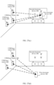
- a communication system includes a first electronic device, a second electronic device, and a first ultra-wideband base station.
- the first electronic device includes an ultra-wideband module and an inertia measurement unit module.
- the first electronic device communicates with the first ultra-wideband base station through ultra-wideband wireless communication, the first electronic device communicates with the second electronic device through another wireless communication, and the another wireless communication is different from the ultra-wideband wireless communication.
- the first electronic device obtains, through the ultra-wideband wireless communication, coordinates of the first electronic device that are based on the first ultra-wideband base station.
- the second electronic device does not include an ultra-wideband module, or the second electronic device includes an ultra-wideband module but the ultra-wideband module is unavailable.
- the first electronic device is configured to perform the method according to any one of the fourth aspect or the implementations of the fourth aspect, any one of the fifth aspect or the implementations of the fifth aspect, any one of the sixth aspect or the implementations of the sixth aspect, any one of the seventh aspect or the implementations of the seventh aspect, any one of the eighth aspect or the implementations of the eighth aspect, or any one of the ninth aspect or the implementations of the ninth aspect.
- a chip system includes one or more interface circuits and one or more processors.
- the interface circuit and the processor are connected to each other through a line.
- the chip system may be applied to a first electronic device including a communication module and a memory.
- the interface circuit is configured to receive a signal from the memory in the electronic device, and send the received signal to the processor, and the signal includes computer instructions stored in the memory.
- the word “example”, “for example”, or the like is for representing giving an example, an illustration, or a description. Any embodiment or design solution described as “example” or “for example” in embodiments of this application should not be explained as being more preferred or having more advantages than another embodiment or design solution. Exactly, use of the word “example”, “for example”, or the like is intended to present a related concept in a specific manner.
- FIG. 1 is a schematic diagram of a scenario of a method for displaying a control window of a second electronic device according to an embodiment of this application.
- a first electronic device 100, a second electronic device 200, a UWB base station 300, a UWB base station 400, and a UWB base station 500 are located in same space.
- the same space includes a same room.
- the first electronic device 100 includes a UWB module.
- the second electronic device 200 does not include a UWB module.
- the UWB module may include at least one of the following: a UWB tag, a UWB chip, and the like.
- the first electronic device 100 may perform wireless communication with the second electronic device 200, and a manner of wireless communication between the first electronic device 100 and the second electronic device 200 includes but is not limited to: wireless fidelity (wireless fidelity, Wi-Fi), Bluetooth (Bluetooth, BT), infrared, and ZigBee (ZigBee).
- the first electronic device 100 and the second electronic device 200 may perform wireless communication through Wi-Fi peer-to-peer (peer-to-peer, P2P).
- the first electronic device 100 and the second electronic device 200 may perform wireless communication through Bluetooth low energy (Bluetooth low energy, BLE).
- the first electronic device 100 and the second electronic device 200 may be located in a same wireless local area network for communication. For example, the first electronic device 100 and the second electronic device 200 access a same router.
- the UWB base station 400 and the UWB base station 500 are not necessary.
- a quantity of UWB base stations is not necessarily at least three, and there may be only one UWB base station, for example, there is only one UWB base station 300.
- the UWB base station 300 needs to include at least three antennas.
- the first electronic device 100, the second electronic device 200, and the UWB base station 300 may form a communication system. That is, there are at least three UWB base stations or there is one UWB base station.
- the communication system may further include a router.
- the first electronic device 100, the second electronic device 200, the UWB base station 300, the UWB base station 400, and the UWB base station 500 may be connected to a same Wi-Fi network by using the router; or the first electronic device 100, the second electronic device 200, and the UWB base station 300 may be connected to a same Wi-Fi network by using the router. This is not limited in this application.
- the first electronic device 100 may integrate control functions of different control devices (for example, a remote control of a smart television and a remote control of a smart air conditioner) of different second electronic devices, so that the first electronic device 100 may locate the second electronic device 200 after pointing to the second electronic device 200, and display a control window of the second electronic device 200.
- the second electronic device 200 needs to be configured with a circuit or module for precise positioning, causing an excessive cost increase of the second electronic device 200. In particular, this requires the foregoing circuit or module to be configured for all second electronic devices, for example, at home or in an office, causing a significant increase in costs.
- a common family or a common company may be unwilling to upgrade all second electronic devices or perform replacement in all second electronic devices due to cost considerations.
- the control window of the second electronic device is also displayed, which is not intended by a user, and therefore brings inconvenience to the user.
- this application provides a first electronic device and a method for displaying a control window of a second electronic device. Even if none of second electronic devices is configured with the foregoing circuit or module for implementing precise positioning, the technical solutions provided in this application can enable a first electronic device of a user to point to a second electronic device that is not configured with the foregoing circuit or module. Moreover, after the first electronic device is located in a front area of the second electronic device and points to the second electronic device, the first electronic device can quickly display a control window of the second electronic device. This brings significant convenience to the user, reduces costs, and improves user experience.
- the first electronic device in a low-cost manner, after the first electronic device points to the second electronic device from the front area of the second electronic device, the first electronic device can quickly display the control window of the second electronic device.
- the first electronic device is configured with a circuit or module for implementing precise positioning
- the second electronic device is not configured with a circuit or module for implementing precise positioning.
- FIG. 2 is a schematic diagram of a hardware structure of a first electronic device according to an embodiment of this application.
- the first electronic device 100 may include a processor 110, an external memory interface 120, an internal memory 121, a universal serial bus (universal serial bus, USB) interface 130, a charging management module 140, a power management module 141, a battery 142, an antenna 1, an antenna 2, an antenna 3, a mobile communication module 150, a wireless communication module 160, a UWB module 161, an IMU module 162, an audio module 170, a speaker 170A, a receiver 170B, a microphone 170C, a headphone jack 170D, a sensor module 180, a key 190, a motor 191, an indicator 192, a camera 193, a display screen 194, a subscriber identification module (subscriber identification module, SIM) card interface 195, and the like.
- SIM subscriber identification module
- the sensor module 180 may include a pressure sensor 180A, a gyroscope sensor 180B, a barometer sensor 180C, a magnetic sensor 180D, an acceleration sensor 180E, a distance sensor 180F, a proximity light sensor 180G, a fingerprint sensor 180H, a temperature sensor 180J, a touch sensor 180K, an ambient light sensor, a bone conduction sensor, and the like.
- the first electronic device 100 is movable.
- the structure illustrated in this embodiment of this application does not constitute a specific limitation on the first electronic device 100.
- the first electronic device 100 may include more or fewer components than those shown in the figure, some components may be combined, some components may be split, or different component arrangements may be used.
- the components shown in the figure may be implemented by hardware, software, or a combination of software and hardware.
- the charging management module 140 is configured to receive charging input from a charger.
- the power management module 141 is configured to connect to the battery 142, the charging management module 140, and the processor 110.
- a wireless communication function of the first electronic device 100 may be implemented by using the antenna 1, the antenna 2, the antenna 3, the UWB module 161, the mobile communication module 150, the wireless communication module 160, a modem processor, a baseband processor, and the like.
- the antenna 1, the antenna 2, and the antenna 3 are configured to transmit and receive electromagnetic wave signals.
- Each antenna in the first electronic device 100 may be configured to cover one or more communication frequency bands. Different antennas may be further reused, to improve antenna utilization.
- the antenna 1 may be reused as a diversity antenna in a wireless local area network.
- the antenna may be used in combination with a tuning switch.
- the mobile communication module 150 may provide a wireless communication solution that includes 2G/3G/4G/5G and that is applied to the first electronic device 100.
- the mobile communication module 150 may include at least one filter, a switch, a power amplifier, a low noise amplifier (low noise amplifier, LNA), and the like.
- the mobile communication module 150 may receive an electromagnetic wave through the antenna 1, perform processing such as filtering or amplification on the received electromagnetic wave, and transmit the electromagnetic wave to the modem processor for demodulation.
- the mobile communication module 150 may further amplify a signal modulated by the modem processor, and convert the signal into an electromagnetic wave for radiation through the antenna 1.
- at least some functional modules of the mobile communication module 150 may be disposed in the processor 110.
- the wireless communication module 160 may provide a wireless communication solution that is applied to the first electronic device 100 and that includes a wireless local area network (wireless local area network, WLAN) (for example, a wireless fidelity network), Bluetooth, a global navigation satellite system (global navigation satellite system, GNSS), frequency modulation (frequency modulation, FM), near field communication (near field communication, NFC), and infrared (infrared, IR).
- WLAN wireless local area network
- WLAN wireless local area network
- GNSS global navigation satellite system
- FM frequency modulation
- NFC near field communication
- IR infrared
- the first electronic device 100 may access a Wi-Fi network by using the wireless communication module 160.
- the first electronic device may send a message to the second electronic device by using the wireless communication module 160.
- the UWB module 161 may be one or more devices integrating at least one communication processing module.
- the UWB module 161 may receive an electromagnetic wave by using the antenna 3, and send a processed signal to the processor 110.
- the UWB module 161 may further receive a to-be-sent signal from the processor 110, and convert the to-be-sent signal into an electromagnetic wave for radiation through the antenna 3.
- the UWB module 161 and the wireless communication module 160 may be integrated together or separately disposed. This is not limited in this application.
- the first electronic device further includes a filter (for example, a Kalman filter).
- a filter for example, a Kalman filter.
- an output of the IMU module 162 and an output of the UWB module 161 may be superimposed, and a signal obtained through the superimposing may be input to a Kalman filter for filtering, thereby reducing an error.
- the GNSS may include a global positioning system (global positioning system, GPS), a global navigation satellite system (global navigation satellite system, GLONASS), a BeiDou navigation satellite system (BeiDou navigation satellite system, BDS), a quasi-zenith satellite system (quasi-zenith satellite system, QZSS), and/or a satellite based augmentation system (satellite based augmentation system, SBAS).
- GPS global positioning system
- GLONASS global navigation satellite system
- BeiDou navigation satellite system BeiDou navigation satellite system
- BDS BeiDou navigation satellite system
- QZSS quasi-zenith satellite system
- SBAS satellite based augmentation system
- the first electronic device 100 may implement a photographing function by using an ISP, the camera 193, a video codec, a GPU, the display screen 194, an application processor, and the like.
- the external memory interface 120 may be configured to connect to an external storage card, for example, a Micro SD card, to extend a storage capability of the first electronic device 100.
- the external memory card communicates with the processor 110 through the external memory interface 120, to implement a data storage function. For example, files such as music and videos are stored in the external storage card.
- the first electronic device 100 may not include the antenna 3 and the UWB module 161, but the UWB module 161 is integrated into the wireless communication module 160.
- a function of communication by the first electronic device 100 with the UWB base station can also be implemented.
- the first electronic device 100 may be a device of a type such as a smartphone, a smart remote control, a wearable device (for example, a smart band, a smart watch, or smart glasses), a palmtop computer, an augmented reality (augmented reality, AR)/virtual reality (virtual reality, VR) device, a portable multimedia player (portable multimedia player, PMP), or a media player.
- a specific type of the first electronic device is not limited in this embodiment of this application.
- FIG. 3 is a schematic diagram of a hardware structure of a second electronic device 200 according to an embodiment of this application.
- the second electronic device 200 may include a processor 210, an external memory interface 220, an internal memory 221, a USB interface 230, a charging management module 240, a power management module 241, a battery 242, an antenna 4, a wireless communication module 250, a sensor module 260, an input module 270, an output module 280, and the like.
- the processor 210 may include one or more processing units.
- the processor 210 may include an application processor (application processor, AP), a modem processor, a GPU, an ISP, a controller, a video codec, a digital signal processor (digital signal processor, DSP), a baseband processor, and/or a neural-network processing unit (neural-network processing unit, NPU).
- the processor 210 may include one or more interfaces.
- the interface may include an inter-integrated circuit (inter-integrated circuit, I2C) interface, an inter-integrated circuit sound (inter-integrated circuit sound, I2S) interface, a pulse code modulation (pulse code modulation, PCM) interface, a universal asynchronous receiver/transmitter (universal asynchronous receiver/transmitter, UART) interface, a mobile industry processor interface (mobile industry processor interface, MIPI), a general-purpose input/output (general-purpose input/output, GPIO) interface, a SIM card interface, a USB interface, and/or the like.
- the USB interface 230 is an interface that conforms to a USB standard specification, and may be specifically a mini USB interface, a micro USB interface, a USB Type-C interface, or the like.
- an interface connection relationship between the modules in this embodiment of this application is merely an example for description, and does not constitute a limitation on the structure of the second electronic device 200.
- the second electronic device 200 may alternatively use different interface connection manners in the foregoing embodiments, or a combination of a plurality of interface connection manners.
- the power management module 241 is configured to connect to the battery 242, the charging management module 240, and the processor 210.
- the power management module 241 receives an input of the battery 242 and/or the charging management module 240, to supply power to the processor 210, the internal memory 221, the external memory interface 220, the wireless communication module 250, and the like.
- the power management module 241 may be further configured to monitor parameters such as a battery capacity, a quantity of battery cycles, and a battery health status (electric leakage and impedance). In some other embodiments, the power management module 241 may alternatively be disposed in the processor 210.
- the external memory interface 220 may be configured to connect to an external memory card, for example, a micro SD card, to extend a storage capability of the second electronic device 200.
- the external storage card communicates with the processor 210 through the external memory interface 220, to implement a data storage function. For example, files such as music and videos are stored in the external storage card.
- the input module 270 includes but is not limited to a keyboard, a touchscreen (which may also be a touchscreen), a mouse, a camera, a laser pen, a handwriting input board, a microphone, and the like.
- the microphone includes a single microphone, or includes a microphone array.
- a manner of wireless communication between the first electronic device and the second electronic device includes but is not limited to a manner of BLE, Wi-Fi awareness (Wi-Fi neighborhood aware network, Wi-Fi neighborhood aware network, NAN for short, also referred to as Wi-Fi aware), ZigBee, or the like.
- the wireless communication such as BLE and Wi-Fi aware is interaction performed based on a medium access control (medium access control, MAC) layer in a computer network, also referred to as interaction performed based on data link layer protocol extension, and does not need to involve upper-layer network communication at the MAC layer, and data interaction can be fully implemented at the data link layer.
- MAC medium access control
- the BLE is an ultra-low power consumption near field wireless communication solution that is launched by a Bluetooth Special Interest Group in 2016 and that is applied to the second electronic device, and may implement communication by using the MAC layer.
- Wi-Fi aware is a new Wi-Fi Mesh communication technology with low power consumption and point-to-point interconnection and interworking.
- the technology can bypass a network infrastructure (such as an access point (access point, AP) or a cellular network) to implement one-to-one, one-to-many, or many-to-many connection and communication between devices, and may also implement communication by using the MAC layer.
- the first electronic device 100 may specifically complete communication with the second electronic device 200 through wireless communication such as BLE or Wi-Fi aware.
- the UWB base station may be an intelligent device (for example, a router, a set-top box, a smart lamp, or a sound box) on which a UWB module is installed.
- the UWB base station may be a separately purchased UWB device.
- a UWB base station, a first electronic device, and a second electronic device establish a first coordinate system, a second coordinate system, and a third coordinate system respectively.
- the UWB base station, the first electronic device, and the second electronic device are started for the first time, the first coordinate system, the second coordinate system, and the third coordinate system are established respectively. Then, the UWB base station, the first electronic device, and the second electronic device may respectively store a coordinate origin, three axes, and positive directions of the three axes of each of the first coordinate system, the second coordinate system, and the third coordinate system locally or on a server. In this way, when the UWB base station, the first electronic device, and the second electronic device are started again, the stored information is obtained locally or from the server, and the first coordinate system, the second coordinate system, and the third coordinate system do not need to be established again.
- the UWB base station, the first electronic device, and the second electronic device each time the UWB base station, the first electronic device, and the second electronic device are started, the UWB base station, the first electronic device, and the second electronic device establish the first coordinate system, the second coordinate system, and the third coordinate system respectively.
- FIG. 6(a) to FIG. 6(d) and FIG. 7 are schematic diagrams of several manners of establishing the first coordinate system in a case of at least three UWB base stations and a case of one UWB base station according to this embodiment of this application.
- FIG. 6(a) distribution of the three UWB base stations may be shown in FIG. 6(a) to FIG. 6(c) .
- the UWB base station distribution manner shown in FIG. 6(a) is a preferred distribution mode of the three UWB base stations.
- a center point of the UWB base station 300 is Oe, and a distance between the UWB base station 300 and the UWB base station 400 is r.
- communication between UWB base stations may include identities of the UWB base stations.
- a direction of a Ye axis is determined based on directions of the Xe axis and the Ze axis and according to a rule of a right-hand rectangular coordinate system (as shown in FIG. 6(d) .
- coordinates of the UWB base station 300, the UWB base station 400, and the UWB base station 500 may be determined.
- coordinates of the UWB base station 500 in the first coordinate system may be determined.
- the Ye axis, a Yb axis, a Yt axis, and positive directions of the Ye axis, the Yb axis, and the Yt axis are determined according to the rule of the right-hand rectangular coordinate system.
- a person skilled in the art should understand that determining the Ye axis, the Yb axis, the Yt axis, and the positive directions of the Ye axis, the Yb axis, and the Yt axis according to the rule of the left-hand rectangular coordinate system or in another manner also falls within the scope of this application.
- names of any two or more axes of any one of the first coordinate system, the second coordinate system, and the third coordinate system may be changed provided that the foregoing rule or manner is met.
- an antenna 0 and an antenna 1 are aligned in a first direction (for example, a horizontal direction), and the antenna 0 and an antenna 2 are aligned in a second direction (for example, a vertical direction). That is, the antenna 0, the antenna 1, and the antenna 2 present an L-shaped distribution relationship.
- the first direction is perpendicular to the second direction.
- the three antennas in the UWB base station may not be presented in an L shape, that is, the first direction is not perpendicular to the second direction.
- the first coordinate system in FIG. 7 may be established with reference to a process of establishing the first coordinate system in FIG. 6(b) and FIG. 6(c) .
- the antennas of the UWB base station in FIG. 7 may present a distribution relationship of a triangle (for example, an equilateral triangle or an isosceles triangle) or the like. This is not limited in this application. It should be noted that a quantity of antennas of the UWB base station in FIG. 7 may be greater than 3.
- the first coordinate system may be established by using a distance difference between a plurality of antennas in the UWB base station.
- coordinates of the antenna 0 may be used as an origin of the first coordinate system
- a connection line between the antenna 0 and the antenna 1 is used as an Xe axis of the first coordinate system
- a direction from the antenna 0 to the antenna 1 is a positive direction of the Xe axis.
- a connection line between the antenna 0 and the antenna 2 is used as a Ze axis of the first coordinate system, and a direction from the antenna 0 to the antenna 2 is a positive direction of the Ze axis.
- a Ye axis of the first coordinate system and a positive direction of the Ye axis are determined according to the rule of the right-hand rectangular coordinate system.
- a connection line between the antenna 0 and the antenna 1 may be used as an Xe axis of the first coordinate system, and a direction from the antenna 1 to the antenna 0 is a positive direction of the Xe axis; and a connection line between the antenna 0 and the antenna 2 is used as a Ze axis of the first coordinate system, and a direction from the antenna 0 to the antenna 2 is a positive direction of the Ze axis.
- a Ye axis of the first coordinate system and a positive direction of the Ye axis are determined according to the rule of the right-hand rectangular coordinate system. It can be learned that, three axes and positive directions of the three axes in the first coordinate system may be established based on relative positions of the three antennas in the UWB base station and according to the rule of the right-hand rectangular coordinate system. For example, as shown in (c) in FIG. 7 , a position of the antenna 0 may be used as an origin of the first coordinate system, a connection line between the antenna 0 and the antenna 1 is used as a Ye axis of the first coordinate system, and a direction from the antenna 1 to the antenna 0 is a positive direction of the Ye axis.
- a connection line between the antenna 0 and the antenna 2 is used as a Ze axis of the first coordinate system, and a direction from the antenna 0 to the antenna 2 is a positive direction of the Ze axis. Then, a positive direction of an Xe axis of the first coordinate system is determined according to the rule of the right-hand rectangular coordinate system. For example, all connection lines between the antennas may be connected by using relative fixed points of the antennas, for example, by using root endpoints of the antennas. In this way, the point Oe may be a root endpoint of the antenna 0. Certainly, the three axes and the positive directions of the three axes in the first coordinate system may also be determined according to the rule of the left-hand rectangular coordinate system or in another manner.
- the foregoing uses the position of the antenna 0 as the origin of the first coordinate system, which is merely an example.
- a location of another antenna (for example, the antenna 1) may alternatively be an origin of the first coordinate system.
- the first coordinate system may be established in advance, provided that the installation personnel install the UWB base station 300, the UWB base station 400, and the UWB base station 500 based on the requirements.
- the first coordinate system is already established, and related information of the first coordinate system is stored locally or on a server.
- the UWB base station 400 needs to be installed on a horizontal left side of the UWB base station 300 on a same plane, and the UWB base station 500 needs to be installed on a vertical upper side of the UWB base station 300 on the same plane.
- FIG. 8 shows a process of establishing the second coordinate system according to this embodiment of this application.
- an edge contour of the first electronic device includes four sides: two vertical sides and two horizontal sides.
- Ob is a center of gravity or a center of the first electronic device.
- An axis that includes the point Ob and that is parallel to the horizontal sides of the first electronic device is an Xb axis, and a positive direction of the Xb axis points to a right side of the first electronic device.
- An axis that includes the point Ob and that is parallel to the vertical sides of the first electronic device is a Yb axis, and a positive direction of the Yb axis points to an upper side of the first electronic device.
- a pointing direction of the first electronic device is the positive direction of the Yb axis.
- a Zb axis is perpendicular to a plane to which the Xb axis and the Yb axis belong, and a positive direction of the Zb axis is determined according to a rule of a right-hand rectangular coordinate system.
- Ob may be a center of the first electronic device, or Ob may be a center of an IMU module of the first electronic device.
- FIG. 8 is a three-dimensional diagram of (a) in FIG. 8 .
- the second coordinate system may be established in advance.
- the first electronic device is delivered from a factory, the first electronic device is already established, and related information of the second coordinate system is stored locally or on a server.
- the first electronic device invokes the related information of the second coordinate system locally or from the server.
- FIG. 9 shows a process of establishing the third coordinate system according to this embodiment of this application.
- an edge contour of the second electronic device includes four sides: a first side A0A1, a second side A1A2, a third side A2A3, and a fourth side A3A0.
- the first side A0A1 and the third side A2A3 are vertical sides
- the second side A1A2 and the fourth side A3A0 are horizontal sides.
- an intersection point that is, a lower left corner of a display area of the second electronic device at which a leftmost side of the display area of the second electronic device intersects with a bottommost side of the display area of the second electronic device is used as a coordinate origin Ot.
- An axis that includes the point Ot and that is parallel to A3A0 is used as an Xt axis, and a positive direction of the Xt axis is a pointing direction from a point A0 to a point A3.
- An axis that includes the point Ot and that is parallel to A0A1 is used as a Yt axis, and a positive direction of the Yt axis is a pointing direction from the point A0 to a point A1.
- a Zt axis is perpendicular to a plane to which the Xt axis and the Yt axis belong, and a positive direction of the Zt axis is determined according to a rule of a right-hand rectangular coordinate system.
- FIG. 9 merely schematically describes the third coordinate system.
- the third coordinate system may also be defined according to another rule.
- Ot may be a center of the display area of the second electronic device, or any point in the display area of the second electronic device.
- positive directions of three axes of the third coordinate system are not limited to the positive directions indicated by the Xt axis, the Yt axis, and the Zt axis shown in FIG. 9 .
- the third coordinate system may be established in advance.
- the third coordinate system is already established, and related information of the third coordinate system is stored locally or on a server.
- the second electronic device invokes the third coordinate system locally or from the server.
- the second coordinate system of the first electronic device may be parallel to the first coordinate system (for example, the Xb axis is parallel to the Xe axis, the Yb axis is parallel to the Ye axis, and the Zb axis is parallel to the Ze axis), and positive directions of corresponding coordinate axes of the two coordinate systems are the same (for example, the positive direction of the Xb axis is the same as the positive direction of the Xe axis, the positive direction of the Yb axis is the same as the positive direction of the Ye axis, and the positive direction of the Zb axis is the same as the positive direction of the Ze axis). All of the elevation angle, the azimuth, and the roll angle that are output by the IMU module of the first electronic device are set to 0.
- the first electronic device calculates coordinates of the first electronic device in real time or periodically. As the first electronic device moves to a position in the display area of the second electronic device, coordinates of the position in the display area of the second electronic device may be marked based on the first electronic device. Similarly, as the first electronic device moves to the position in the front area of the second electronic device, coordinates of the position in the front area of the second electronic device are marked by using the coordinates of the first electronic device in the first coordinate system.
- the first electronic device may obtain a distance between the first electronic device and the UWB base station and the coordinates of the first electronic device in the first coordinate system. Because the first electronic device can learn of a coordinate origin, three axes, and positive directions of the three axes of the second coordinate system that correspond to the first electronic device, the first electronic device can convert the coordinates in the first coordinate system into coordinates in the second coordinate system based on the direction change of the second coordinate system relative to the first coordinate system.
- the UWB communication is performed periodically or in real time.
- the first electronic device has a consistent pointing direction, orientation, and the like at the at least three different positions, that is, an orientation, a pointing direction, and the like of the first electronic device are not limited during the marking.
- the sending includes broadcast.
- the foregoing broadcast may be broadcast at a specific period.
- the period may be preset, or may be adjusted by a user.
- the first communication message includes a randomly generated unique identification code for identifying the first communication message, to avoid confusion.
- T d may be 0.
- the UWB base station 300 obtains the unique identification address of the first electronic device 100 from the first communication message.
- the first electronic device 100 may calculate a distance L1 between the first electronic device 100 and the UWB base station 300 by using a formula (1).
- L 1 T r ⁇ T s ⁇ T d ⁇ c / 2 c is the speed of light.
- the first communication message may alternatively be sent by the UWB base station 300.
- the first response message may alternatively be sent by the first electronic device 100, and the UWB base station 300 calculates L1 based on the foregoing time difference and the formula (1).
- the following data is known: coordinates (0 e , 0 e , 0 e ) of the point Oe, coordinates ( d 1 e , 0 e , 0 e ) of a point O1, coordinates (0 e , 0 e , d 2 e ) of a point O2, a distance L1 between ObOe, a distance L2 between ObO1, and a distance L3 between ObO2.
- the first electronic device outputs fourth prompt information, where the fourth prompt information is for prompting the first electronic device to mark the fourth position.
- S1101, S 1103, S 1105, and S 1107 are all optional steps, and are not mandatory steps.
- any two of the first position, the second position, the third position, and the fourth position are different positions.
- the first position, the second position, and the third position are respectively a lower left corner, an upper left corner, and a lower right corner of the display area of the second electronic device.
- the first position, the second position, and the third position are respectively a lower left corner, an upper left corner, and a lower right corner of the second electronic device.
- the second electronic device has no border
- the lower left corner, the upper left corner, and the lower right corner of the display area of the second electronic device are respectively the same as the lower left corner, the upper left corner, and the lower right corner of the second electronic device.
- the fourth position may be a position that is outside the second electronic device and that is in the front area of the second electronic device.
- first position, the second position, and the third position are respectively the lower left corner, the upper left corner, and the lower right corner of the display area of the second electronic device
- fourth position is the position that is outside the second electronic device and that is in the front area of the second electronic device for description.
- first position, the second position, the third position, and the fourth position may be respectively positions of the first electronic device shown in FIG. 12(a), FIG. 12(b) , FIG. 12(c), and FIG. 12(d) .
- the first electronic device when the first electronic device is separately placed at three vertex angles (the lower left corner, the upper left corner, and the lower right corner) of the display area of the second electronic device, the first electronic device may be placed in a same posture.
- the center of the first electronic device when the first electronic device is placed at each vertex angle, the center of the first electronic device may be located at the vertex angle, and a vertical contour of the first electronic device may be parallel to the vertical contour of the display area of the second electronic device (or a horizontal contour of the first electronic device may be parallel to the horizontal contour of the display area of the second electronic device).
- the foregoing "display area of the second electronic device” may all be replaced with “second electronic device”. If the second electronic device has a border, the foregoing "display area of the second electronic device” may also be replaced with "second electronic device”.
- all or some of the coordinates of the first electronic device, the coordinates of the at least three positions in the display area of the second electronic device, coordinates of the UWB base station, and the coordinates of the position in the front area of the second electronic device are converted into coordinates in a same coordinate system based on a relative direction change between coordinate systems. This facilitates subsequent calculation and determining.
- the first position relationship between the first electronic device and the second electronic device includes whether the first electronic device is located in the front area of the second electronic device; and the first position relationship between the first electronic device and the second electronic device includes whether the first electronic device points to the second electronic device.
- the first electronic device displays the control window of the second electronic device when determining that the first electronic device is located in the front area of the second electronic device and points to the second electronic device.
- the coordinates in the first coordinate system need to be converted into coordinates in another coordinate system, for example, converted into coordinates in the second coordinate system or coordinates in the third coordinate system.
- a relative direction change between different coordinate systems may be expressed by an elevation (pitch) angle ⁇ , an azimuth (yaw) ⁇ , and a roll (roll) angle ⁇ between coordinate systems.
- the azimuth may also be referred to as a yaw or a course angle.
- the elevation angle, the azimuth, and the roll angle are an elevation angle, an azimuth, and a roll angle of the second coordinate system relative to the first coordinate system, or an elevation angle, an azimuth, and a roll angle of the third coordinate system relative to the first coordinate system.
- coordinate origins of the three coordinate systems are all aggregated to one point.
- the coordinate origin Oe of the UWB base station is moved in parallel to the coordinate origin Ob of the second coordinate system.
- the first coordinate system also moves accordingly.
- Definitions of the elevation angle, the azimuth, and the roll angle are well known to a person skilled in the art, and are not described herein.
- the roll angle ⁇ e b of the second coordinate system relative to the first coordinate system is an angle between the Zb axis of the second coordinate system and the plane YbOeZe.
- ⁇ e b is an angle between ObZb' and the Zb axis.
- ⁇ e b is positive; when the Xb-axis component of the projection of ObZb' on the plane XbObYb is located on a negative Xb axis, ⁇ e b is negative.
- FIG. 14 shows the elevation angle ⁇ e t , the azimuth ⁇ e t , and the roll angle ⁇ e t of the third coordinate system relative to the first coordinate system.
- the coordinate origin Ot of the third coordinate system coincides with a coordinate origin Oe of the first coordinate system that is obtained after parallel movement
- three axes of the third coordinate system are an Xt axis, a Yt axis, and a Zt axis
- three axes of the first coordinate system are an Xe axis, a Ye axis, and a Ze axis.
- OeYt' that is, OtY t'
- OeZt' is a projection of the Zt axis on the plane YtOeZe.
- the elevation angle ⁇ e t of the third coordinate system relative to the first coordinate system is an angle between the Yt axis of the third coordinate system and the plane XeOeYe of the first coordinate system, ⁇ e t is an angle between OeYt' (that is, OtYt') and the Yt axis.
- OeYt' that is, OtYt'
- cpe When a Ze-axis component of OeYt is located on a positive Ze axis, cpe is positive; and when the Ze-axis component of OeYt is located on a negative Ze axis, cpe is negative.
- the azimuth ⁇ e t of the third coordinate system relative to the first coordinate system is an angle between a projection of the Yt axis of the third coordinate system on the plane XeOeYe of the first coordinate system and the Ye axis of the first coordinate system.
- ⁇ e t is an angle between OeYt' (that is, OtYt') and the Ye axis.
- the roll angle ⁇ e t of the third coordinate system relative to the first coordinate system is an angle between the Zt axis of the third coordinate system and the plane YtOeZe.
- ⁇ e t is an angle between OtZt' and the Zt axis.
- ⁇ e t is positive; when the Xt-axis component of the projection of OtZt' on the plane XtOtYt is located on a negative Xt axis, ⁇ e t is negative.
- the direction change of the third coordinate system relative to the first coordinate system may be expressed by using an attitude matrix C e t .
- C e t cos ⁇ e t cos ⁇ e t + sin ⁇ e t sin ⁇ e t sin ⁇ e t sin ⁇ e t ⁇ cos ⁇ e t sin ⁇ e t + sin ⁇ e t sin ⁇ e t cos ⁇ e t cos ⁇ e t sin ⁇ e t cos ⁇ e t sin ⁇ e t cos ⁇ e t sin ⁇ e t sin ⁇ e t sin ⁇ e t sin ⁇ e t cos ⁇ e t sin ⁇ e t sin ⁇ e t cos ⁇ e t sin ⁇ e t sin ⁇ e t cos ⁇ e t sin ⁇ e t sin ⁇ e t sin ⁇ e t cos ⁇ e t sin ⁇ e t sin ⁇ e t sin ⁇ e
- attitude matrix C e t is a conventional technology, and a person skilled in the art may obtain the formula from the conventional technology.
- attitude matrix in 1.2.1 of Chapter 1 of the book “Inertial Navigation” (Beijing: Science Press, ISBN 7-03-016428-8, by Qin Yongyuan, 1st edition in May 2006, 1st print in May 2006 ).
- UWB base stations may be replaced with one UWB base station including three antennas.
- a related calculation manner is similar to the foregoing calculation manner. Details are not described herein again.
- the UWB base station when there is only one UWB base station and the UWB base station includes three antennas, after receiving a positioning request sent by a first electronic device (for example, the first electronic device), different antennas may measure a signal coming direction of the positioning request, and send a response signal based on a fixed delay, where the response signal includes information about the measured signal coming direction.
- the first electronic device calculates a distance between the first electronic device and the UWB base station, and calculates spatial position information of the first electronic device in a coordinate system by using a spatial position of the UWB base station and the signal coming direction measured by the UWB base station.
- Chinese Patent Application No. 202011636500.6 entitled “Indoor Positioning Method, Terminal, and System", which is incorporated herein by reference in its entirety.
- a relative direction change of the third coordinate system relative to the first coordinate system may be specifically represented by using a mathematical matrix Ce.
- the following still uses the example in which the first electronic device marks the lower left corner, the upper left corner, and the lower right corner of the display area of the second electronic device and one position in the front area for description.
- the length of the vertical contour of the display area of the second electronic device is m
- the length of the horizontal contour of the display area of the second electronic device is n
- the first electronic device marks the lower left corner, the upper left corner, and the lower right corner of the display area of the second electronic device and the position in the front area as A0, A1, A3, and B0 respectively.
- the point B0 coincides with the point Ob
- the point B0 is a fixed point in space, and remains fixed even if the first electronic device 100 moves the point B0.
- the point Ob represents a center of gravity or a center of the first electronic device 100, and the point Ob moves as the first electronic device 100 moves.
- the first electronic device 100 may obtain coordinates ( x A0 e , y A0 e , z A0 e ) of A 0 e , coordinates ( x A1 e , y A1 e , z A1 e ) of A 1 e , coordinates ( x A3 e , y A3 e , z A3 e ) of A 3 e , and coordinates ( x B0 e , y B0 e , z B0 e ) of B 0 e , that is, may obtain coordinates of A0, A1, A3, and B0 in the first coordinate system.
- lengths of a vector A 0 A 1 and a vector A 0 A 3 are m and n respectively.
- the vector A 0 A 1 and the vector A 0 A 3 are expressed as ( A 0 A 1 ) e and ( A 0 A 3 ) e respectively.
- the vector A 0 A 1 and the vector A 0 A 3 are expressed as ( A 0 A 1 ) t and ( A 0 A 3 ) t respectively.
- ⁇ e t , ⁇ e t , and ⁇ e t may be calculated based on the foregoing formula (11) and formula (12).
- the elevation angle, the azimuth, and the roll angle of the second electronic device relative to the first coordinate system meet the following angle range conditions: ⁇ ⁇ e t ⁇ ⁇ ⁇ 2 , ⁇ 2 ⁇ e t ⁇ ⁇ ⁇ 2 , ⁇ 2 ⁇ e t ⁇ ⁇ ⁇ , ⁇
- a value of ⁇ e t in the formula (16) is related to positive and negative values of arcsin ⁇ z A3 e ⁇ z A0 e m ⁇ cos ⁇ e t , and when arcsin ⁇ z A3 e ⁇ z A0 e m ⁇ cos ⁇ e t ⁇ 0 or arcsin ⁇ z A3 e ⁇ z A0 e m ⁇ cos ⁇ e t ⁇ 0 , there are also two values.
- z B0 may be obtained through calculation after the plurality of values of C e t are substituted. If z B0 is less than or equal to 0, B0 does not match the position in the front area of the second electronic device, and therefore a value of ⁇ e t is discarded. If z B0 is greater than 0, B0 matches the position in the front area of the second electronic device, and therefore a value of ⁇ e t is reserved.
- the first electronic device After it is determined that the first electronic device is located in the front area of the second electronic device, whether the first electronic device points to the second electronic device is further determined. It should be noted that if z B1 is less than or equal to 0, it indicates that the first electronic device is located on the back of the second electronic device. In this case, the procedure shown in FIG. 5 may be directly exited, and a subsequent procedure is not continued.
- a point Q is selected on a Yb axis of the second coordinate system.
- q is known data.
- q 1.
- the IMU module of the first electronic device may output Cb in real time.
- Q b , O b e , and Ob are known data. Therefore, Q e may be calculated based on the formula (21). Then, because C e t , A 0 e , and A 0 t are known data, and Q e has been calculated based on the formula (21), Q t may be calculated based on the formula (22).
- the IMU module of the first electronic device may output the elevation angle, the azimuth, and the roll angle in real time.
- a processor of the first electronic device may obtain real-time Cb through calculation in real time based on the elevation angle, the azimuth, and the roll angle that are output in real time. Because Q b , O b e , and Ob are known data, Q e may be calculated based on the formula (21). Then, because C e t , A 0 e , and A 0 t are known data and Q e has been calculated based on the formula (21), Q t may be calculated based on the formula (22).
- Cb is a conventional technology, and may be obtained by a person skilled in the art from the conventional technology, for example, the attitude update algorithm in 4.1.2 of Chapter 4 of the book “Strapdown Inertial Navigation Algorithm and Principle of Integrated Navigation” (Northwestern Polytechnical University Press, ISBN 978-7-5612-6547-5, by Yan Gongmin and Weng Jun, 1st edition in August 2019, 2nd print in January 2020 ).
- coordinates of the point Q in the third coordinate system are (5, 3, 2)
- coordinates of the point Ob in the third coordinate system are (3, 2, 1)
- O b Q ⁇ tx , O b Q ⁇ ty , and O b Q ⁇ tz are 2, 1, and 1 respectively.
- O b tx , O b ty , and O b tz are an Xt coordinate, a Yt coordinate, and a Zt coordinate of the point Ob in the third coordinate system.
- O b Q ⁇ tx , O b Q ⁇ ty , and O b Q ⁇ tz are an Xt-axis component, a Yt-axis component, and a Zt-axis component of the vector O b Q in the third coordinate system.
- ⁇ O b tz ⁇ ⁇ O b Q tx O b Q ⁇ tx + O b tx , ⁇ O b tz ⁇ ⁇ O b Q ty O b Q ⁇ tz + O b ty , 0 t O b Q ⁇ tx , O b Q ⁇ ty , O b Q ⁇ tz , O b tx , and O b ty , O b tz may be obtained through calculation.
- the second electronic device may also include an IMU module.
- the second electronic device may obtain the direction information of the second electronic device by using the IMU module of the second electronic device.
- the second electronic device may communicate with the first electronic device periodically or in real time, for example, through short-distance wireless communication.
- the short-distance wireless communication includes but is not limited to Bluetooth, Wi-Fi communication, and the like.
- the first electronic device may obtain the orientation information of the second electronic device.
- the first electronic device obtains pointing direction information of the first electronic device by using the IMU module of the first electronic device.
- the first electronic device may determine, based on the pointing direction information of the first electronic device, the orientation information of the second electronic device, and the position information of the second electronic device, whether the first electronic device points to the second electronic device.
- the first electronic device when marking the second electronic device, only needs to mark at least three positions on the second electronic device, and a fourth time of marking is not required.
- the first electronic device only needs to mark three different positions of the second electronic device, such as the lower left corner, the upper left corner, and the lower right corner.
- S4 and S5 may be exchanged in order.
- S5 uses the manner 2. In this case, S5 may be performed first, and then S4 is performed.
- the first electronic device automatically displays the control window of the second electronic device after it is determined that the first electronic device is located in the front area of the second electronic device and points to the second electronic device in the foregoing process. In this way, the first electronic device automatically displays or displays the control window of the second electronic device provided that the user places the first electronic device in the front area of the second electronic device and the first electronic device points to the second electronic device. Further, if the second electronic device includes a display screen, the display screen of the second electronic device displays a cursor corresponding to a position pointed by the first electronic device. For the user, this increases convenience, and reduces misjudgment, and therefore user experience is better.
- UI interfaces that may be displayed by the first electronic device and the second electronic device in the method provided in this embodiment of this application.
- the first electronic device may receive a tapping operation performed by the user on an icon "Smart Life” 601. "Smart Life” may be considered as a smart home app.
- the first electronic device may start the Smart Life app, and display a home interface (which may also be referred to as a device manager) 602 of the Smart Life app shown in FIG. 16(b) .
- the home interface 602 includes icons of a plurality of second electronic devices bound to the Smart Home app.
- the plurality of second electronic devices include the foregoing second electronic device (for example, the foregoing second electronic device may be a television in a living room).
- a mobile phone may display, by default, the device manager 602 shown in FIG.
- the first electronic device may receive a tapping operation performed by the user on a "Home" control 604a.
- the first electronic device may display a device manager 602 shown in FIG. 16(b) .
- the first electronic device may be triggered, by using an "Add device" control 604b, to search for a second electronic device, to bind the corresponding second electronic device.
- the first electronic device may receive an operation performed by the user on an icon 603 on the second electronic device (for example, a television in a living room), where the operation may be any operation performed by the user on the icon on the second electronic device, such as a touch and hold operation, a tap operation, or a double-tap operation.
- an operation performed by the user on an icon 603 on the second electronic device for example, a television in a living room
- the operation may be any operation performed by the user on the icon on the second electronic device, such as a touch and hold operation, a tap operation, or a double-tap operation.
- the first electronic device in response to an operation performed by the user on the icon 603 on the second electronic device shown in FIG. 16(b) , as shown in FIG. 17 , the first electronic device may display a shortcut function menu 605, and the shortcut function menu 605 may include a plurality of operation controls (for example, "On", "Off", and "Mark”).
- a "Mark” control 606 is for triggering the first electronic device to mark a position of the second electronic device.
- the first electronic device may mark the position of the second electronic device.
- the first electronic device in response to an operation performed by the user on the icon 603 of the second electronic device shown in FIG. 16(b) , as shown in FIG. 18 , the first electronic device may display a control interface 607 of the second electronic device.
- the control interface 607 of the second electronic device may include an icon on the second electronic device and operation controls such as "On", "Off", and "Mark”.
- an operation for example, a tap operation
- the first electronic device may mark the position of the second electronic device.
- the first electronic device displays a prompt interface 610 shown in FIG. 19(a) .
- the prompt interface 610 includes first prompt information, for example, "Please sequentially place the first electronic device at the lower left corner, the upper left corner, and the lower right corner of the second electronic device, and the position in the front area of the screen of the second electronic device, and provide confirmation sequentially".
- the first electronic device may further output the first prompt information in a voice manner.
- the first electronic device may output the first prompt information in two manners: a voice manner and a display manner.
- an icon 611a may blink to prompt the user to place the first electronic device at a lower left corner of the second electronic device.
- the user may operate (for example, tap) an "OK" key 611b.
- the first electronic device may record current spatial position information of the first electronic device.
- an icon 613a may blink to prompt the user to place the first electronic device at an upper left corner of the second electronic device.
- the user may tap an "OK" key 613b.
- the first electronic device may record current spatial position information of the first electronic device.
- an icon 615a may blink to prompt the user to place the first electronic device at a lower right corner of the second electronic device.
- the user may operate an "OK" key 615b.
- the first electronic device may record current spatial position information of the first electronic device.
- an icon 617a may blink to prompt the user to place the first electronic device at a position in the front area of the second electronic device. After the user places the first electronic device at the position in the front area of the second electronic device, the user may operate an "OK" key 617b. In this case, the first electronic device may record current spatial position information of the first electronic device.
- the second electronic device may be installed with an application (for example, a "Settings" application) having a function of marking the position of the second electronic device.
- the first electronic device may be a mobile phone, a remote control, or another device.
- the first electronic device includes a display screen.
- the remote control includes a display screen.
- An example in which the first electronic device is a remote control is used for description. The user starts the second electronic device by using the remote control, and controls, based on an input on the remote control, an application on the second electronic device to enable a corresponding function (for example, controlling a "Settings" application on the second electronic device to enable a universal remote control function), so that the second electronic device starts to accept a position mark.
- the user may operate (for example, tap) a "Mark" key 620 on the remote control, and in response to the operation performed by the user on the "Mark” key 620, the second electronic device may display a prompt interface 622.
- the prompt interface 622 includes first prompt information 623, for example, "Please sequentially place the first electronic device at the lower left corner, the upper left corner, and the lower right corner of the second electronic device, and in the front area of the screen of the second electronic device, and provide confirmation sequentially".
- first prompt information 623 for example, "Please sequentially place the first electronic device at the lower left corner, the upper left corner, and the lower right corner of the second electronic device, and in the front area of the screen of the second electronic device, and provide confirmation sequentially".
- the second electronic device may further display second prompt information, to prompt that the remote control is located in the front area of the second electronic device and points to the second electronic device, so that the control window of the second electronic device can be displayed on a display screen 621 of the remote control.
- the second prompt information may be displayed for preset duration (for example, 10 seconds).
- the display of the first prompt information and/or the second prompt information may be replaced with a voice output, or may be replaced with display and a voice output.
- the first electronic device marks the position of the second electronic device.
- position marking and orientation marking on the second electronic device for which no UWB module is configured may be performed, to determine a specific position and orientation of the second electronic device in space.
- the first electronic device can quickly display the control window of the second electronic device, to facilitate user control, reduce a user operation, save time, and improve user experience.
- the first electronic device 100 when the user enables the first electronic device 100 located in the front area of the second electronic device 200 to point to the second electronic device 200, the first electronic device 100 immediately displays the control window 201 of the second electronic device 200.
- the control window 201 may be an interface displayed in full screen, or may be a window that does not occupy full screen.
- the control window 201 may be displayed on the display screen in a floating manner, or may be fixedly displayed at a position on the display screen.
- the control window 201 may be displayed at a top layer of the display interface. The user can perform subsequent control on the second electronic device without performing an unnecessary operation, and user experience is good.
- the first electronic device calculates and obtains the coordinates of the first electronic device in the first coordinate system in real time through real-time communication interaction between the first electronic device and the UWB base station, obtains coordinates of three different positions on the second electronic device and coordinates of a position in front of a screen area of the second electronic device through marking by the first electronic device, and converts all or some of the coordinates of the first electronic device, the coordinates of the three different positions on the second electronic device, the coordinates of the position in front of the screen area of the second electronic device, and the coordinates of the UWB base station into coordinates in a same coordinate system based on a relative direction change between coordinate systems.
- the first electronic device points to the front area of the second electronic device.
- the first electronic device determines, based on the pointing direction information of the first electronic device, the orientation information of the second electronic device, and the position information of the second electronic device, that the first electronic device points to the second electronic device.
- the first electronic device After the first electronic device is located in the front area of the second electronic device and points to the second electronic device, the first electronic device displays the control window of the second electronic device.
- the method for displaying the control window of the second electronic device includes the following steps.
- a UWB base station, a first electronic device, and a second electronic device establish a first coordinate system, a second coordinate system, and a third coordinate system respectively.
- Specific content of S2210 is the same as specific content of S510. Refer to the descriptions of S510. Details are not described herein again.
- an orientation of the first electronic device at the position is limited, and even an orientation, a pointing direction, and the like are all limited.
- the orientation of the first electronic device is the same as an orientation of the second electronic device.
- the orientation of the first electronic device is the same as an orientation of the second electronic device, where a pointing direction of the first electronic device is upward and parallel to a vertical side or a horizontal side of an edge contour of the second electronic device, or a pointing direction of the first electronic device is upward and parallel to a vertical side or a horizontal side of the display area of the second electronic device (for example, as shown in (a) in FIG.
- the first electronic device may be placed in a landscape manner, or may be placed in a portrait manner).
- the first electronic device receives a user input, and the first electronic device records coordinates, an orientation, and the like of the first electronic device at the position, which are respectively used as coordinates of the position in the display area of the second electronic device and the orientation of the second electronic device.
- the second electronic device may tilt by a specific angle.
- the orientation of the first electronic device is the same as the orientation of the second electronic device, and the pointing direction of the first electronic device is upward and parallel to a vertical side or a horizontal side of the second electronic device, or the pointing direction of the first electronic device is upward and parallel to the vertical side or the horizontal side of the display area of the second electronic device.
- an orientation of the first electronic device at one of the two positions is limited, and even an orientation, a direction, and the like are all limited.
- the orientations of the first electronic device at the two positions are the same.
- the two locations are a first position and a second position.
- orientations of the first electronic device at the first position and the second position are the same as an orientation of the second electronic device.
- pointing directions of the first electronic device at the first position and the second position are the same.
- an orientation of the first electronic device at the first position is limited, and even an orientation, a pointing direction, and the like are all limited.
- an orientation, a pointing direction, and the like of the first electronic device at the second position are not limited. That is, the orientation and the pointing direction of the first electronic device at the second position may be performed based on the foregoing limitation, or may not be performed based on the foregoing limitation.
- the first electronic device When the first electronic device is at the first position, the first electronic device receives a first user input, and records coordinates, an orientation, and the like of the first electronic device at the first position, which are respectively used as coordinates of the first position in the display area of the second electronic device and an orientation of the second electronic device.
- the first electronic device receives a second user input, and records coordinates of the first electronic device at the second position as coordinates of the second position in the display area of the second electronic device.
- the first electronic device may further record an orientation of the first electronic device, and use the recorded orientation as an orientation of the second electronic device.
- the first electronic device may obtain, through calculation, a more accurate orientation of the second electronic device based on the orientations of the second electronic device that are recorded.
- one or two positions in the display area of the second electronic device may be one position (for example, at a position of 1/2 or 1/3) or two positions of an edge contour (for example, a horizontal contour or a vertical contour of the display area) of the display area of the second electronic device, or may be one position (for example, a central point of the display area) or two positions (for example, an intersection of a horizontal side center and a vertical side center of the display area, and an intersection of a horizontal side center and 1/3 of a vertical side of the display area) in a central part of the display area of the second electronic device.
- the first electronic device if the first electronic device marks only one position (for example, a vertex angle position) in the display area of the second electronic device, the first electronic device needs to obtain a length of a vertical contour and a length of a horizontal contour of the display area of the second electronic device.
- the length of the vertical contour and the length of the horizontal contour of the display area of the second electronic device may be obtained by the second electronic device in advance; and the second electronic device transmits the length of the vertical contour and the length of the horizontal contour to the first electronic device through short-distance wireless communication (for example, Bluetooth or Wi-Fi) with the first electronic device.
- short-distance wireless communication for example, Bluetooth or Wi-Fi
- the first electronic device can obtain the length of the vertical contour and the length of the horizontal contour of the display area of the second electronic device. If the first electronic device cannot obtain the length of the vertical contour and the length of the horizontal contour of the display area of the second electronic device from the second electronic device, the first electronic device may mark two positions in the display area of the second electronic device. Two vertex angle positions, namely, a lower left corner and an upper right corner (or two vertex angle positions: an upper left corner and a lower right corner) of the display area are used as an example. In this case, the IMU module of the first electronic device may output a relative direction change of the second coordinate system relative to the first coordinate system.
- a 2 t ⁇ A 0 t C e t ⁇ A 2 e ⁇ A 0 e
- values of m and n may be calculated by using a horizontal coordinate difference and a vertical coordinate difference between A2 and A0 in the third coordinate system.
- z B1 in the third coordinate system may be obtained based on the formula (20). It is determined, based on that z B1 in the third coordinate system obtained in the foregoing calculation process is greater than 0, that the first electronic device is located in the front area of the second electronic device.
- the first electronic device After the first electronic device is located in the front area of the second electronic device and points to the second electronic device, the first electronic device displays the control window of the second electronic device.
- FIG. 23 is a schematic flowchart of marking, by the first electronic device, the second electronic device in the method for displaying the control window of the second electronic device according to an embodiment of this application. As shown in FIG. 23 , the procedure includes the following steps.
- the first electronic device receives a user input, and outputs first prompt information, where the first prompt information is for prompting the first electronic device to sequentially mark a first position in the display area of the second electronic device and a fourth position that is outside the second electronic device and that is in the front area of the second electronic device.
- the first prompt information in S2301 is for prompting the first electronic device to mark a first position on the second electronic device.
- the first electronic device After the first electronic device moves to the first position, where an orientation and a pointing direction of the first electronic device maintain correspondences with an orientation and a pointing direction of the second electronic device, the first electronic device receives a first input, records coordinates of the first electronic device as coordinates of the first position, and records, through conversion based on the correspondences, the orientation and the pointing direction of the first electronic device as the orientation and the pointing direction of the second electronic device.
- the orientation and the pointing direction of the first electronic device are the same as the orientation and the pointing direction of the second electronic device.
- the orientation of the first electronic device is the same as the orientation of the second electronic device, and the pointing direction of the first electronic device is upward and parallel to a vertical side or a horizontal side of the second electronic device, or the pointing direction of the first electronic device is upward and parallel to a vertical side or a horizontal side of the display area of the second electronic device (for example, as shown in (a) in FIG. 24 , the first electronic device may be placed in a landscape manner, or may be placed in a portrait manner).
- the first electronic device receives the first input, records the coordinates of the first electronic device as the coordinates of the first position, and records the orientation and the pointing direction of the first electronic device as the orientation and the pointing direction of the second electronic device.
- a user needs to execute, as far as possible, the orientation, the pointing direction, and the like of the first electronic device at the position based on the foregoing operation.
- the orientation of the first electronic device is opposite to the orientation of the second electronic device, and the pointing direction of the first electronic device is the same as the pointing direction of the second electronic device.
- the orientation of the first electronic device is opposite to the orientation of the second electronic device, and the pointing direction of the first electronic device is upward and parallel to a vertical side or a horizontal side of the second electronic device, or the pointing direction of the first electronic device is upward and parallel to a vertical side or a horizontal side of the display area of the second electronic device.
- the first electronic device receives the first input, records the coordinates of the first electronic device as the coordinates of the first position, records a direction opposite to the orientation of the first electronic device as the orientation of the second electronic device, and records the pointing direction of the first electronic device as the pointing direction of the second electronic device.
- a user needs to implement, as far as possible, the orientation, the pointing direction, and the like of the first electronic device at the position based on the foregoing operation.
- the user may be reminded of information such as the orientation and the pointing direction of the first electronic device at the first position by outputting prompt information.
- the prompt information may be included in the first prompt information, or new prompt information may be output in addition to the first prompt information to remind the user.
- S2301 is an optional step, and is not a mandatory step.
- the first position may be one of a lower left corner, an upper left corner, and a lower right corner of the display area of the second electronic device.
- the first position may be one of a lower left corner, an upper left corner, and a lower right corner of the second electronic device.
- the second electronic device has no border, the lower left corner, the upper left corner, and the lower right corner of the display area of the second electronic device are respectively the same as the lower left corner, the upper left corner, and the lower right corner of the second electronic device.
- that the first electronic device is located at the first position means that the first electronic device is near the lower left corner of the display area of the second electronic device.
- the first electronic device may be placed close to the lower left corner of the display area of the second electronic device.
- spatial coordinates of the first electronic device in the first coordinate system are spatial coordinates of the lower left corner of the display area of the second electronic device in the first coordinate system.
- the spatial coordinates corresponding to the lower left corner in the first coordinate system are more accurate.
- information such as the orientation and the pointing direction of the first electronic device is obtained by using information output by the IMU module of the first electronic device, and information such as the orientation and the pointing direction of the second electronic device can be obtained, so that a position of only one vertex angle of the second electronic device needs to be marked, without marking positions of a plurality of vertex angles of the second electronic device.
- the first position may be a position by the first electronic device shown in (a) in FIG. 24 .
- the first position may be a position by the first electronic device shown in (a) in FIG. 25 .
- the first electronic device displays the control window of the second electronic device when the first electronic device is located in the front area of the second electronic device and points to the second electronic device.
- Specific content of S2230 is the same as specific content of S530. Refer to the descriptions of S530. Details are not described herein again.
- the first electronic device is located in the front area of the second electronic device and points to the second electronic device.
- the first electronic device displays the control window of the second electronic device.
- the first electronic device is located in the front area of the second electronic device and points to the second electronic device.
- the first electronic device displays the control window of the second electronic device.
- the foregoing "display area of the second electronic device” may all be replaced with “second electronic device”. If the second electronic device has a border, the foregoing "display area of the second electronic device” may also be replaced with "second electronic device”.
- the coordinates of the first position recorded by the first electronic device and the corresponding meaning may be locally stored in the first electronic device, may be stored on a cloud server (where the first electronic device may be connected to the cloud server) connected to the first electronic device, or may be stored on a home central device (not shown in the figure) connected to the first electronic device.
- a home may be equipped with one home central device.
- the home central device and various electronic devices in the home may be connected to a same router.
- a third electronic device may obtain the coordinates of the first position and the corresponding meanings through communication connection to the home central device, to obtain position information and orientation information of the second electronic device.
- a mobile phone of a husband is the first electronic device
- a mobile phone of a wife is the second electronic device.
- the husband marks a television by using the mobile phone of the husband.
- the mobile phone of the husband obtains position information and orientation information of the television, and stores the position information and the orientation information of the television on a home central device.
- the mobile phone of the wife may obtain the position information and the orientation information of the television from the home central device. Therefore, when the mobile phone of the wife is located in a front area of the television and points to the television, the mobile phone of the wife also displays a control window of the television.
- the mobile phone of the husband only needs to mark the television once, and the mobile phone of the wife does not need to mark the television.
- the mobile phone of the husband or the mobile phone of the wife displays the control window of the television.
- the first electronic device includes but is not limited to the mobile phone
- the second electronic device includes but is not limited to the television.
- a UI interface that may be displayed by the second electronic device in the method provided in this embodiment of this application.
- the first electronic device in response to the operation (for example, the tapping operation) performed by the user on the "Mark” control 606, the first electronic device may display a prompt interface 630 shown in FIG. 26 .
- the first electronic device in response to the operation (for example, the tapping operation) performed by the user on the "Mark” control 608, the first electronic device may display a prompt interface 630 shown in FIG. 26 .
- the prompt interface 630 includes second prompt information 631, for example, "Please place the first electronic device at the lower left corner of the second electronic device, keep the pointing direction of the first electronic device upward and parallel to the vertical side of the second electronic device, keep the orientation of the first electronic device the same as a screen orientation of the second electronic device, and provide confirmation".
- the first electronic device may further output the second prompt information in a voice playing manner.
- a control 632 may blink, to prompt the user to place the first electronic device at the lower left corner of the second electronic device, keep the pointing direction of the first electronic device upward and parallel to a vertical side of the second electronic device, and keep the orientation of the first electronic device the same as a screen orientation of the second electronic device.
- the user may place the first electronic device based on the second prompt information, that is, place the first electronic device at the lower left corner of the second electronic device, keep the pointing direction of the first electronic device upward and parallel to the vertical side of the second electronic device, and keep the screen/panel orientation of the first electronic device the same as the screen orientation of the second electronic device.
- the user may tap an "OK" key 633.
- the first electronic device may record current information such as the coordinates, the orientation, and the pointing direction of the first electronic device.
- the method provided in this embodiment of this application may be applied to the second electronic device with no UWB module.
- the first electronic device only needs to mark a position on the second electronic device once, where the mark includes a mark of coordinates of the display area of the second electronic device and a mark of information (for example, a tilt angle) such as an orientation.
- the first electronic device only needs to mark two positions on the second electronic device twice, where the two times of marking include marking of coordinates of the two positions in the display area of the second electronic device, and at least one of the two times of marking includes marking of information (for example, a tilt angle) such as an orientation of the second electronic device.
- the second electronic device does not need to include a UWB module.
- the first electronic device when the first electronic device is located in the front area of the second electronic device and points to the second electronic device, the first electronic device can quickly display the control window of the second electronic device, so that it is convenient for the user to control the second electronic device, time is saved, and user experience is improved.
- the first electronic device needs to obtain at least coordinates of the first electronic device at a vertex angle of the display area of the second electronic device and information (for example, a tilt angle) such as an orientation, and uses the coordinates of the first electronic device and the orientation as information such as coordinates of the vertex angle of the second electronic device and the orientation of the second electronic device.
- the first electronic device may further obtain information such as an orientation of the first electronic device when the first electronic device is located at another vertex angle of the display area of the second electronic device, and the first electronic device corrects the information such as the orientation of the second electronic device based on the information such as the orientation s that are obtained twice, so that the obtained information such as the orientation of the second electronic device is more accurate.
- the first electronic device may further obtain coordinates of the first electronic device at the another vertex angle of the display area of the second electronic device, and use the coordinates of the first electronic device as coordinates of the another vertex angle of the display area of the second electronic device, to facilitate subsequent calculation of the length of the vertical contour and the length of the horizontal contour of the display area of the second electronic device.
- the vertex angle position of the display area of the second electronic device is merely an example of the first position and the second position in the display area of the second electronic device, and other positions (for example, a central position of the display area of the second electronic device, a position at a center of a vertical side and 1/3 of a horizontal side of the display area of the second electronic device) also fall within the scope of this application.
- the first position, the second position, and the third position may be M1, M2, and M3 shown in FIG. 27(a) to FIG. 27(d) .
- the second electronic device may display M1, M2, and M3 (and may further display corresponding prompt information), which are for representing the first position, the second position, and the third position respectively, so that the user goes to a corresponding position for marking.
- the second electronic device may sequentially display M1, M2, and M3 (and may further display the corresponding prompt information), to sequentially indicate the first position, the second position, and the third position, so that the user goes to a corresponding position for marking.
- any one of M1, M2, and M3 may automatically disappear and not be displayed after preset duration.
- the first electronic device may obtain a length and a width of an edge contour of the second electronic device through calculation based on coordinate values of the first position, the second position, and the third position in the first coordinate system.
- the first electronic device may obtain a length and a width of an edge contour of the display area of the second electronic device through calculation based on coordinate values of the first position, the second position, and the third position in the first coordinate system.
- the method for displaying the control window of the second electronic device provided in this embodiment of this application is applicable to the following first electronic device and second electronic device.
- FIG. 28 shows a first electronic device 2800 according to this application.
- the first electronic device 2800 includes at least one processor 2810, a memory 2820, and a display screen 2830.
- the processor 2810 is coupled to the memory 2820 and the display screen 2830.
- the coupling in this embodiment of this application may be a communication connection, or may be in an electrical form, or in another form.
- the memory 2820 is configured to store program instructions.
- the display screen 2830 is configured to display a user interface.
- the processor 2810 is configured to invoke the program instructions stored in the memory 2820, so that the first electronic device 2800 performs steps performed by the first electronic device in the method for displaying the control window of the second electronic device provided in embodiments of this application.
- the display screen when the display screen has a touch function, the display screen is also referred to as a touch display screen. An operation on the touch display screen may be implemented by using a virtual key.
- the display screen When the display screen has no touch function, the display screen is also referred to as a non-touch display screen. An operation on the non-touch display screen may be implemented by using a physical button.
- This application provides a computer program product including instructions.
- the computer program product runs on a first electronic device
- the first electronic device is enabled to perform steps performed by the first electronic device in the method for displaying the control window of the second electronic device provided in embodiments of this application.
- This application provides a computer-readable storage medium, including instructions.
- the instructions When the instructions are run on a first electronic device, the first electronic device is enabled to perform steps performed by the first electronic device in the method for displaying the control window of the second electronic device provided in embodiments of this application.
- embodiments of this application may be implemented by hardware, or by hardware and software.
- the foregoing functions may be stored in a computer-readable medium.
- the computer software product is stored in a storage medium and includes several instructions for instructing a computer device (which may be a personal computer, a server, or a network device) to perform all or some of the steps of the methods described in embodiments of this application.
- the foregoing storage medium includes: any medium that can store program code, such as a flash memory, a removable hard disk, a read-only memory, a random access memory, a magnetic disk, or an optical disc.
Landscapes
- Engineering & Computer Science (AREA)
- Signal Processing (AREA)
- Multimedia (AREA)
- Human Computer Interaction (AREA)
- General Engineering & Computer Science (AREA)
- Theoretical Computer Science (AREA)
- Physics & Mathematics (AREA)
- General Physics & Mathematics (AREA)
- Computer Networks & Wireless Communication (AREA)
- Databases & Information Systems (AREA)
- Mobile Radio Communication Systems (AREA)
Applications Claiming Priority (3)
| Application Number | Priority Date | Filing Date | Title |
|---|---|---|---|
| CN202110351270 | 2021-03-31 | ||
| CN202110872916.6A CN115150646B (zh) | 2021-03-31 | 2021-07-30 | 一种显示第二电子设备控制窗口的方法及第一电子设备 |
| PCT/CN2022/083828 WO2022206786A1 (zh) | 2021-03-31 | 2022-03-29 | 一种显示第二电子设备控制窗口的方法及第一电子设备 |
Publications (2)
| Publication Number | Publication Date |
|---|---|
| EP4296801A1 true EP4296801A1 (de) | 2023-12-27 |
| EP4296801A4 EP4296801A4 (de) | 2024-04-03 |
Family
ID=83404882
Family Applications (1)
| Application Number | Title | Priority Date | Filing Date |
|---|---|---|---|
| EP22778968.2A Pending EP4296801A4 (de) | 2021-03-31 | 2022-03-29 | Verfahren zur anzeige eines steuerfensters einer zweiten elektronischen vorrichtung und erste elektronische vorrichtung |
Country Status (4)
| Country | Link |
|---|---|
| US (1) | US12432409B2 (de) |
| EP (1) | EP4296801A4 (de) |
| CN (1) | CN115150646B (de) |
| WO (1) | WO2022206786A1 (de) |
Families Citing this family (5)
| Publication number | Priority date | Publication date | Assignee | Title |
|---|---|---|---|---|
| KR20230036848A (ko) * | 2021-09-08 | 2023-03-15 | 삼성전자주식회사 | 적어도 하나의 uwb 장치를 제어하기 위한 사용자 경험을 제공하는 전자 장치 및 그 제어 방법 |
| US12369011B2 (en) * | 2022-05-06 | 2025-07-22 | Hewlett Packard Enterprise Development Lp | Location identification of access points in a network |
| WO2024085376A1 (en) | 2022-10-18 | 2024-04-25 | Samsung Electronics Co., Ltd. | Method and electronic device for displaying position of first device on second device |
| CN118068970A (zh) * | 2024-04-17 | 2024-05-24 | 深圳华云时空技术有限公司 | 一种基于imu和uwb融合技术的空鼠定位系统 |
| US20250343969A1 (en) * | 2024-05-02 | 2025-11-06 | Directv, Llc | Methods and apparatus to position antennas |
Family Cites Families (17)
| Publication number | Priority date | Publication date | Assignee | Title |
|---|---|---|---|---|
| CN108351400A (zh) * | 2015-11-10 | 2018-07-31 | Xco技术有限公司 | 用于超宽带位置定位的系统和方法 |
| KR102627518B1 (ko) * | 2016-09-02 | 2024-01-23 | 엘지전자 주식회사 | 싱크 디바이스 및 그 제어 방법 |
| WO2018127209A1 (zh) * | 2017-01-09 | 2018-07-12 | 苏州宝时得电动工具有限公司 | 自移动设备及其定位系统、定位方法和控制方法 |
| CN106792476B (zh) * | 2017-01-09 | 2020-03-31 | 苏州佳世达电通有限公司 | 建立通讯连接的方法以及建立通讯连接的系统 |
| TWI628631B (zh) * | 2017-05-08 | 2018-07-01 | 和碩聯合科技股份有限公司 | 遙控系統、遙控方法與閘道器 |
| CN108012326B (zh) * | 2017-12-07 | 2019-06-11 | 珠海市一微半导体有限公司 | 基于栅格地图的机器人监视宠物的方法及芯片 |
| CN110007841B (zh) * | 2019-03-29 | 2021-05-18 | 联想(北京)有限公司 | 一种控制方法和电子设备 |
| CN110568767B (zh) * | 2019-07-31 | 2021-01-29 | 华为技术有限公司 | 一种智能家居设备选择方法及终端 |
| CN110536243A (zh) * | 2019-08-27 | 2019-12-03 | 全图通位置网络有限公司 | 一种超宽带定位通信一体化终端 |
| CN111007455B (zh) | 2019-10-16 | 2024-04-30 | 张苏 | 定位系统及方法、数据库、神经网络模型训练方法 |
| CN111212182B (zh) * | 2019-12-01 | 2021-06-25 | 深圳市纽瑞芯科技有限公司 | 用嵌uwb模块的手机直接遥控uwb设备的方法及装置 |
| CN111610923B (zh) * | 2020-04-26 | 2022-08-05 | 北京小米移动软件有限公司 | 定向操作方法、定向操作装置及存储介质 |
| CN111885705B (zh) * | 2020-07-28 | 2022-11-08 | 广东艾罗照明科技股份有限公司 | 基于uwb的灯具定位系统、方法及装置 |
| CN112134995A (zh) * | 2020-08-05 | 2020-12-25 | 华为技术有限公司 | 一种查找应用对象的方法、终端及计算机可读存储介质 |
| CN112327653B (zh) | 2020-11-13 | 2025-08-26 | 北京小米移动软件有限公司 | 设备控制方法、设备控制装置及存储介质 |
| CN112327944A (zh) * | 2020-11-20 | 2021-02-05 | Oppo广东移动通信有限公司 | 一种电子设备控制方法、装置、电子设备及存储介质 |
| US20240300555A1 (en) * | 2021-09-08 | 2024-09-12 | China Railway Engineering Services Co., Ltd. | Method and system for three dimensional positioning in subway construction site, and medium |
-
2021
- 2021-07-30 CN CN202110872916.6A patent/CN115150646B/zh active Active
-
2022
- 2022-03-29 EP EP22778968.2A patent/EP4296801A4/de active Pending
- 2022-03-29 US US18/552,833 patent/US12432409B2/en active Active
- 2022-03-29 WO PCT/CN2022/083828 patent/WO2022206786A1/zh not_active Ceased
Also Published As
| Publication number | Publication date |
|---|---|
| US20240171802A1 (en) | 2024-05-23 |
| WO2022206786A1 (zh) | 2022-10-06 |
| EP4296801A4 (de) | 2024-04-03 |
| CN115150646B (zh) | 2024-06-11 |
| CN115150646A (zh) | 2022-10-04 |
| US12432409B2 (en) | 2025-09-30 |
Similar Documents
| Publication | Publication Date | Title |
|---|---|---|
| EP4296801A1 (de) | Verfahren zur anzeige eines steuerfensters einer zweiten elektronischen vorrichtung und erste elektronische vorrichtung | |
| US12219631B2 (en) | Controlling electronic devices based on wireless ranging | |
| US12137399B2 (en) | Short-distance information transmission method and electronic device | |
| CN108513335B (zh) | 电子设备及确定其接入点设备的合适位置的方法 | |
| CN110568767A (zh) | 一种智能家居设备选择方法及终端 | |
| US20240319312A1 (en) | Method for Obtaining Posture Information and Electronic Device | |
| EP4171135A1 (de) | Vorrichtungssteuerungsverfahren und zugehörige vorrichtung | |
| US12586457B2 (en) | Home device position marking method and electronic device | |
| CN107148783A (zh) | 用于扫描相邻设备的方法及其电子设备 | |
| WO2021077923A1 (zh) | 控制显示设备的方法及便携设备 | |
| KR20160046340A (ko) | 장치 검색 방법 및 이를 지원하는 전자 장치 | |
| CN107493311B (zh) | 实现操控设备的方法、装置和系统 | |
| CN108432160B (zh) | 在无线通信系统中基于声音信号发送和接收数据的设备和方法 | |
| KR20150129592A (ko) | 이동 단말기 및 이동 단말기의 제어방법 | |
| EP4250775B1 (de) | Verfahren und system zum schnellen auftauchen eines steuerfensters einer elektronischen vorrichtung und mobile vorrichtung | |
| CN115016298A (zh) | 一种智能家居设备选择方法及终端 | |
| CN208190894U (zh) | 一种音箱设备及系统 | |
| WO2022206751A1 (zh) | 一种输入设备复用的跨设备协同方法及电子设备 | |
| CN108476261B (zh) | 移动装置以及控制移动装置的方法 | |
| CN114339695A (zh) | 定位方法及相关装置 | |
| CN115720249A (zh) | 一种显示方法、电子设备及系统 | |
| KR101985326B1 (ko) | 휴대 장치의 출력음 정위 제어 방법 및 그 휴대 장치 | |
| CN114765564B (zh) | 一种家居设备的控制方法及电子设备 | |
| KR20240072163A (ko) | 초광대역 통신을 이용한 비-초광대역 장치의 제어를 위한 방법 및 장치 | |
| CN119817120A (zh) | 在无线通信系统中通过使用uwb控制非uwb设备的方法和装置 |
Legal Events
| Date | Code | Title | Description |
|---|---|---|---|
| STAA | Information on the status of an ep patent application or granted ep patent |
Free format text: STATUS: THE INTERNATIONAL PUBLICATION HAS BEEN MADE |
|
| PUAI | Public reference made under article 153(3) epc to a published international application that has entered the european phase |
Free format text: ORIGINAL CODE: 0009012 |
|
| STAA | Information on the status of an ep patent application or granted ep patent |
Free format text: STATUS: REQUEST FOR EXAMINATION WAS MADE |
|
| 17P | Request for examination filed |
Effective date: 20230921 |
|
| AK | Designated contracting states |
Kind code of ref document: A1 Designated state(s): AL AT BE BG CH CY CZ DE DK EE ES FI FR GB GR HR HU IE IS IT LI LT LU LV MC MK MT NL NO PL PT RO RS SE SI SK SM TR |
|
| REG | Reference to a national code |
Ref country code: DE Ref legal event code: R079 Free format text: PREVIOUS MAIN CLASS: G05B0015020000 Ipc: H04W0004020000 |
|
| A4 | Supplementary search report drawn up and despatched |
Effective date: 20240306 |
|
| RIC1 | Information provided on ipc code assigned before grant |
Ipc: G05B 15/02 20060101ALI20240229BHEP Ipc: H04N 21/442 20110101ALI20240229BHEP Ipc: H04N 21/41 20110101ALI20240229BHEP Ipc: G06F 3/04847 20220101ALI20240229BHEP Ipc: G06F 3/04812 20220101ALI20240229BHEP Ipc: H04N 21/422 20110101ALI20240229BHEP Ipc: H04W 88/08 20090101ALI20240229BHEP Ipc: H04W 88/02 20090101ALI20240229BHEP Ipc: H04W 4/80 20180101ALI20240229BHEP Ipc: H04W 4/02 20180101AFI20240229BHEP |
|
| DAV | Request for validation of the european patent (deleted) | ||
| DAX | Request for extension of the european patent (deleted) |