EP4295663A1 - Ballenaufnahmevorrichtung zur aufnahme von rundballen einer rundballenpresse - Google Patents
Ballenaufnahmevorrichtung zur aufnahme von rundballen einer rundballenpresse Download PDFInfo
- Publication number
- EP4295663A1 EP4295663A1 EP23181072.2A EP23181072A EP4295663A1 EP 4295663 A1 EP4295663 A1 EP 4295663A1 EP 23181072 A EP23181072 A EP 23181072A EP 4295663 A1 EP4295663 A1 EP 4295663A1
- Authority
- EP
- European Patent Office
- Prior art keywords
- receiving device
- bale
- coupling
- drawbar
- bale receiving
- Prior art date
- Legal status (The legal status is an assumption and is not a legal conclusion. Google has not performed a legal analysis and makes no representation as to the accuracy of the status listed.)
- Pending
Links
- 230000008878 coupling Effects 0.000 claims abstract description 92
- 238000010168 coupling process Methods 0.000 claims abstract description 92
- 238000005859 coupling reaction Methods 0.000 claims abstract description 92
- 230000005540 biological transmission Effects 0.000 description 1
- 230000005484 gravity Effects 0.000 description 1
- 239000000463 material Substances 0.000 description 1
- 230000000284 resting effect Effects 0.000 description 1
- 239000007787 solid Substances 0.000 description 1
Images

Classifications
-
- A—HUMAN NECESSITIES
- A01—AGRICULTURE; FORESTRY; ANIMAL HUSBANDRY; HUNTING; TRAPPING; FISHING
- A01B—SOIL WORKING IN AGRICULTURE OR FORESTRY; PARTS, DETAILS, OR ACCESSORIES OF AGRICULTURAL MACHINES OR IMPLEMENTS, IN GENERAL
- A01B59/00—Devices specially adapted for connection between animals or tractors and agricultural machines or implements
- A01B59/04—Devices specially adapted for connection between animals or tractors and agricultural machines or implements for machines pulled or pushed by a tractor
-
- A—HUMAN NECESSITIES
- A01—AGRICULTURE; FORESTRY; ANIMAL HUSBANDRY; HUNTING; TRAPPING; FISHING
- A01F—PROCESSING OF HARVESTED PRODUCE; HAY OR STRAW PRESSES; DEVICES FOR STORING AGRICULTURAL OR HORTICULTURAL PRODUCE
- A01F15/00—Baling presses for straw, hay or the like
- A01F15/08—Details
- A01F15/0875—Discharge devices
- A01F15/0883—Discharge devices for round balers
-
- A—HUMAN NECESSITIES
- A01—AGRICULTURE; FORESTRY; ANIMAL HUSBANDRY; HUNTING; TRAPPING; FISHING
- A01D—HARVESTING; MOWING
- A01D87/00—Loaders for hay or like field crops
- A01D87/12—Loaders for sheaves, stacks or bales
- A01D87/125—Loaders for sheaves, stacks or bales mounted on the press without laying down the bales
-
- A—HUMAN NECESSITIES
- A01—AGRICULTURE; FORESTRY; ANIMAL HUSBANDRY; HUNTING; TRAPPING; FISHING
- A01D—HARVESTING; MOWING
- A01D90/00—Vehicles for carrying harvested crops with means for selfloading or unloading
- A01D90/02—Loading means
- A01D90/08—Loading means with bale-forming means additionally used for loading; with means for picking-up bales and transporting them into the vehicle
- A01D90/083—Round-bale trailers
-
- A—HUMAN NECESSITIES
- A01—AGRICULTURE; FORESTRY; ANIMAL HUSBANDRY; HUNTING; TRAPPING; FISHING
- A01F—PROCESSING OF HARVESTED PRODUCE; HAY OR STRAW PRESSES; DEVICES FOR STORING AGRICULTURAL OR HORTICULTURAL PRODUCE
- A01F15/00—Baling presses for straw, hay or the like
- A01F15/07—Rotobalers, i.e. machines for forming cylindrical bales by winding and pressing
-
- B—PERFORMING OPERATIONS; TRANSPORTING
- B60—VEHICLES IN GENERAL
- B60D—VEHICLE CONNECTIONS
- B60D1/00—Traction couplings; Hitches; Draw-gear; Towing devices
- B60D1/14—Draw-gear or towing devices characterised by their type
- B60D1/145—Draw-gear or towing devices characterised by their type consisting of an elongated single bar or tube
-
- B—PERFORMING OPERATIONS; TRANSPORTING
- B60—VEHICLES IN GENERAL
- B60D—VEHICLE CONNECTIONS
- B60D1/00—Traction couplings; Hitches; Draw-gear; Towing devices
- B60D2001/001—Traction couplings; Hitches; Draw-gear; Towing devices specially adapted for use on vehicles other than cars
- B60D2001/008—Traction couplings; Hitches; Draw-gear; Towing devices specially adapted for use on vehicles other than cars specially adapted for implements, e.g. towed tools
-
- B—PERFORMING OPERATIONS; TRANSPORTING
- B60—VEHICLES IN GENERAL
- B60P—VEHICLES ADAPTED FOR LOAD TRANSPORTATION OR TO TRANSPORT, TO CARRY, OR TO COMPRISE SPECIAL LOADS OR OBJECTS
- B60P3/00—Vehicles adapted to transport, to carry or to comprise special loads or objects
- B60P3/035—Vehicles adapted to transport, to carry or to comprise special loads or objects for transporting reel units
Definitions
- the invention relates to a bale receiving device for receiving at least one round bale from a round baler.
- the invention further relates to a vehicle combination comprising the bale pick-up device.
- the bale receiving device comprises a coupling device with at least one coupling frame element, which is designed for stationary arrangement on a machine frame of the round baler.
- the bale receiving device comprises at least one drawbar element which extends at least partially in a receiving direction between the coupling frame element and a machine frame of the bale device.
- the drawbar element is mounted on the coupling device in such a way that it can be pivoted relative to the coupling frame element at least about a vertical axis, which is arranged at right angles to a contact surface of the bale receiving device at least in a first position of the coupling device.
- bale receiving device has become known as a bale wrapper, which is to be attached to the round baler and is designed to wrap the round bale with a wrapping material.
- the known bale receiving device is disadvantageous, on the one hand, because the coupling device and the drawbar element are only one allow slight pivoting of the round baler relative to the bale receiving device, which limits the curve radius that can be achieved during operation and regularly leads to collisions between the coupling device and the bale receiving device.
- the bale receiving device is disadvantageous, since the coupling device and the drawbar element itself are designed to taper towards the vertical axis in such a way to enable the slight pivoting that there is a gap on the side of the vertical axis between the coupling device and the drawbar element, into which the round bale falls while being picked up from the Round baler can fall sideways before it has reached the machine frame of the bale pick-up device.
- the object of the present invention is to provide a generic bale pick-up device and a vehicle combination comprising the bale pick-up device, which avoid the disadvantages described above.
- the bale receiving device has a transfer element.
- the transfer element is mounted on the coupling device and can be pivoted relative to the drawbar element at least about the vertical axis.
- the transfer element extends in the receiving direction in such a way that the drawbar element is at least partially arranged between the transfer element and the contact surface in a side view or a longitudinal section.
- the bale pick-up device is in particular a vehicle that is to be coupled to the round baler and includes its own chassis.
- the Bale receiving device preferably forms a receiving section for the round bale that adjoins the round baler, in particular a press chamber thereof. Due to the standardized round bale dimensions, the receiving section preferably has a width of at least 1.20 m and a height of at least 1.20 m.
- the bale receiving device is preferably designed to hold and transport several, in particular at least four, round bales.
- the bale receiving device is preferably designed in such a way that the round bales are not displaced laterally from their position in the baling chamber when they are picked up (in-line recording).
- the coupling frame element is in particular to be fixed immovably to the machine frame of the round baler, preferably screwed.
- the bale receiving device preferably has two coupling frame elements that are offset from one another transversely to the receiving direction.
- the at least one coupling frame element is, in particular, lower link catch hooks, which have proven themselves in agriculture for attaching work machines.
- the imaginary vertical axis is preferably arranged centrally in a front view of the bale receiving device, that is to say within a longitudinal center plane.
- the longitudinal center plane is spanned by the vertical axis and a longitudinal axis running in a direction of travel in which the bale receiving device is to be moved across the field during operation.
- the coupling device is in particular designed to be mirror-symmetrical to the longitudinal center plane.
- the recording direction is preferably perpendicular to the vertical axis and/or at least partially aligned against the direction of travel.
- the contact area is an imaginary, flat surface that adjoins the chassis, preferably wheels, of the bale pick-up device without cutting it, and extends in the direction of travel and / or corresponds to the ground surface of the field, provided it is flat.
- the vertical axis runs vertically when the contact area extends horizontally and the coupling device is arranged in the first position.
- the vertical axis runs at an angle of ⁇ 90° to the contact surface.
- the drawbar element connects the coupling device to the machine frame of the bale receiving device.
- the machine frame is preferably designed to be rigid with respect to a chassis axis of the bale receiving device and/or preferably has at least two side longitudinal beams.
- the drawbar element is preferably not pivotable relative to the machine frame about a pivot axis that is angled to the contact surface.
- the drawbar element preferably comprises a central support which extends against the receiving direction from the machine frame to the coupling device and is subject to tension.
- the drawbar element can be pivoted relative to the coupling frame element by approximately 140° about the vertical axis.
- the transfer element is arranged such that at least part of it is arranged above at least part of the drawbar element during operation.
- the Transfer element extends from the coupling device preferably in the receiving direction beyond the vertical axis.
- the transfer element is in particular mounted in such a way that it is not pivotally movable relative to the coupling frame element about an axis that is angled to the contact surface, such as the vertical axis.
- the transfer element therefore does not follow a pivoting of the machine frame of the bale receiving device relative to the round baler during operation.
- the transfer element preferably extends mainly elongated and relatively flat in the receiving direction and/or parallel to the main extension direction of the drawbar element.
- the transfer element solves the problem in that, on the one hand, the coupling device and/or the drawbar element can be made so narrow or tapered to the vertical axis that the drawbar element can be pivoted sufficiently far relative to the coupling device in agricultural operations. On the other hand, the round bale is prevented from falling into the gap by the transfer element bridging it.
- the transfer element is designed in particular in such a way that a collision with it during pivoting is excluded.
- the transfer element is mounted on the coupling device in such a way that it is pivotally movable relative to the coupling frame element about a transverse axis parallel to the contact surface.
- the imaginary transverse axis is positioned in particular in a stationary manner relative to the coupling frame element. Due to the pivoting bearing in this way of the transfer element, in the event of a change in the incline and/or slope of the field on which the bale pick-up device is operated, it can adjust its position in favor of reliable pick-up of the round bale.
- the vertical axis and the transverse axis are preferably arranged in such a way that they do not intersect, that is, that they are spaced apart from one another.
- the vertical axis is arranged offset in relation to the transverse axis, particularly in the recording direction.
- the drawbar element is mounted on the coupling device in such a way that it is pivotally movable relative to the coupling frame element about an axis parallel to the contact surface.
- the drawbar element is mounted in such a way that it is pivotally movable about the transverse axis relative to the coupling frame element, just like the transfer element.
- the transfer element is mounted on the coupling device in such a way that it can be pivoted about the transverse axis relative to the drawbar element.
- the transfer element and the drawbar element are not only pivotable relative to the coupling frame element, but also relative to each other about the transverse axis. This reduces the risk of the pivoting movement of the drawbar element being blocked reduced relative to the transfer element around the vertical axis and the transfer element can move upwards.
- the transfer element and the drawbar element are not mounted so that they can pivot relative to one another about the transverse axis, which means that the probability of failure can be reduced by saving a joint elsewhere.
- the coupling device preferably has an intermediate coupling element that is mounted on the coupling frame element so that it can pivot only about the transverse axis and that is mounted on the drawbar element so that it can only pivot about the vertical axis. Thanks to the intermediate coupling element, the above-described pivoting movements can be implemented using two separate joints, each of which only allows one pivoting direction, the probability of failure of which is lower than that of a complex joint. In addition, with the intermediate coupling element, part of the coupling device can contribute to receiving the round bale. To further simplify the design, the transfer element is preferably mounted on the intermediate coupling element away from the coupling frame element.
- the transfer element preferably has a radial extent related to the transverse axis, which, at least in a straight-ahead position of the bale receiving device, corresponds to at least half, preferably two thirds, particularly preferably three quarters or more, of the distance of the machine frame of the bale receiving device from the transverse axis.
- the transfer element is preferably designed such that its radial extent is variable.
- at least one The end of the transfer element facing the machine frame of the bale receiving device is formed by an adjustable extension element.
- the bale pick-up device is positioned in the straight-ahead position during operation when the bale pick-up device is moved straight ahead, that is, without cornering, in the field. Due to the radial extent of the transfer element, it reaches close to the machine frame of the bale receiving device and in particular has a length that is at least similar to the length of the drawbar element. This minimizes the risk of the round bale falling between the machine frame and the transfer element.
- the distance of the vertical axis from the machine frame of the bale receiving device is at least as large as the distance of the vertical axis from the transverse axis.
- the distance between the vertical axis and the machine frame is at least twice as large or even at least five times as large as the distance between the vertical axis and the transverse axis.
- the vertical axis can be arranged particularly far forward, in particular below the press chamber of the round baler, which results in several advantages. On the one hand, this reduces the pivoting angle of the drawbar element relative to the coupling device around the vertical axis when cornering in a comparable manner and results in more stable driving dynamics achieved by the bale pick-up device.
- this arrangement of the vertical axis allows the round bale to be picked up even at least when cornering or pivoting angles around the vertical axis.
- the bale receiving device preferably has at least one drawbar adjusting element.
- the drawbar adjusting element is designed to pivot the drawbar element relative to the machine frame of the bale receiving device about a drawbar pivot axis, which is arranged parallel to the transverse axis in the straight-ahead position of the bale receiving device.
- the drawbar actuating element is in particular a hydraulic cylinder.
- the bale receiving device preferably has two drawbar adjusting elements which are arranged on two opposite sides of the machine frame.
- the drawbar control element allows the drawbar element and the machine frame to be lowered into a V-shape at least to a large extent and in particular down to the contact area, whereupon the receiving direction is directed downwards. When lowered, the round bale reaches the machine frame of the bale pick-up device more easily because of gravity.
- the drawbar element is rigidly arranged on the machine frame.
- the transfer element preferably has a support section for supporting the transfer element on the drawbar element.
- the transfer element rests with the support section on the drawbar element during operation.
- the support section in particular has a surface directed towards the contact area on.
- the transfer element is therefore preferably mounted in the front area on the coupling device, in particular on the intermediate coupling element, and in the rear area on the drawbar element. This storage is advantageous regardless of whether the transfer element can be pivoted about the transverse axis relative to the drawbar element.
- the support section is advantageous in that the weight of a round bale resting above the drawbar element on the transfer element does not have to be derived solely via the coupling device and the transfer element has to be made correspondingly solid, but rather directly on the drawbar element and in particular consequently at least partially on the chassis of the bale receiving device is to be derived.
- the support section and/or its described surface particularly preferably extends at least essentially or exactly in a circular arc shape around the vertical axis.
- the support section is formed by a tube with a cross section that is symmetrical to a center line, the center line extending in a circular arc around the vertical axis.
- the support section preferably extends by at least 90°, in particular at least by the maximum pivot angle of the drawbar element relative to the coupling frame element around the vertical axis.
- a ball bearing or a plain bearing in particular made of plastic, is arranged between the drawbar element and the transfer element.
- the plain bearing is in particular as a between the drawbar element and a friction-reducing plastic element, for example a plastic plate, arranged on the transfer element, preferably on the drawbar element.
- the ball bearing or an alternative roller or barrel bearing is particularly advantageous if the transfer element is not pivotable about the transverse axis relative to the drawbar element.
- the ball bearing or the plain bearing achieves the advantageous power transmission without causing wear and tear that endangers the reliability of the two receiving devices.
- the transfer element preferably has at least two transfer sections which extend elongated in the receiving direction, between which the drawbar element extends at least partially in a plan view at least in the straight-ahead position.
- the drawbar element extends in particular elongated in the longitudinal center plane.
- the transfer sections extend offset from the longitudinal center plane and elongated parallel to it and are in particular designed to be mirror-symmetrical to the longitudinal center plane.
- the transfer sections allow the round bale to roll smoothly in the pickup direction.
- the transfer element is in particular designed in one piece and/or rigidly.
- the transfer sections are preferably welded to the support section and in particular to a cross member of the transfer element which extends parallel to the transverse axis.
- the object is further achieved by a vehicle combination comprising the round baler described above and/or below and the bale receiving device described above and/or below, which is coupled to the round baler.
- the at least one coupling frame element is arranged in a stationary manner on a machine frame of the round baler.
- the round baler is preferably a self-propelled round baler or one that is attached to a tractor during operation.
- the coupling frame element is to be considered as being enclosed by the machine frame of the round baler.
- the transfer element and the drawbar element do not have to be supported on the same component of the machine frame of the round baler.
- the at least one coupling frame element is arranged on a chassis axle encompassed by the machine frame of the round baler.
- the chassis axle is a rigid component on which wheels are mounted laterally and which extends horizontally below the press chamber.
- the vertical axis can in practice be arranged particularly far forward in order to achieve the advantages described above.
- the transverse axis is arranged in particular behind the chassis axle, that is to say offset in the receiving direction from the chassis axle. This makes it possible to reliably guide the round bale to the machine frame of the bale pick-up device.
- the Fig. 1, 2 and 6 show a vehicle combination 26 according to the invention comprising a round baler 4 pulled by a tractor 30 and a bale pick-up device 2 coupled to the round baler 4.
- the bale pick-up device 2 is used to pick up several round bales, not shown, from the round baler 4 in order to be able to deposit the round bales in a collected manner and not afterwards having to pick up each round bale individually.
- the bale receiving device 2 comprises a coupling device 6.
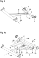
- the coupling device 6 comprises two coupling frame elements 8, which are arranged in a stationary manner on a vehicle axle 32 of a machine frame 10 of the round baler 4 (cf. Fig. 3 and 4 ).
- the coupling device 6 comprises an intermediate coupling element 18.
- the intermediate coupling element 18 is mounted on the coupling frame elements 8 so that it can pivot about a transverse axis HA.
- a drawbar element 14 is mounted on the intermediate coupling element 18 so that it can pivot about a vertical axis VA.
- a longitudinal axis LA is in particular arranged at right angles to both the vertical axis VA and the transverse axis HA, at least in one position.
- the drawbar element 14 extends in a receiving direction AR between the intermediate coupling element 18 and a machine frame 12 of the receiving device 2.
- the vertical axis VA extends at least in a first position of the coupling device 6 at right angles to a contact area AF of the bale receiving device 2 (cf. Fig. 1 ).
- a transfer element 16 is mounted on the intermediate coupling element 18 so that it can pivot about the transverse axis HA.
- the transfer element 16 is immovable relative to the coupling device 6 about the vertical axis VA or an axis parallel thereto (cf. Fig. 4 and 7 ).
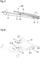
- the transfer element 16 extends in the receiving direction AR in such a way that the drawbar element 14 in the longitudinal section or the side view Fig. 5 is at least partially arranged between the transfer element 16 and the contact surface AF.
- the transfer element 16 has a radial extension A related to the transverse axis HA, which corresponds to at least two thirds of a distance B of the machine frame 12 of the bale receiving device 2 from the transverse axis HA (cf. Fig. 5 ).
- the radial extent of the bale receiving device 2 is as follows Fig. 8 variable by screwed extension elements 34 of the transfer element 16.
- a distance C of the vertical axis VA from the machine frame 12 of the bale receiving device 2 (cf. Fig. 8 ) at least five times as large as a distance D of the vertical axis VA from the transverse axis (cf. Fig. 5 ).
- the bale receiving device 2 has two drawbar adjusting elements 20, which are designed to pivot the drawbar element 14 relative to the machine frame 12 of the bale receiving device 2 about a drawbar pivot axis DA, which is in the with Fig. 1 and 2
- the straight-ahead position of the bale receiving device 2 shown runs parallel to the transverse axis HA (cf. Fig. 8 ).
- the transfer element 16 has a support section 22 which extends in a circle around the vertical axis VA and which is in the Fig. 4a , 7 and 8 is shown in simplified form consisting of straight elements that are angled towards one another.
- the support section 22 serves to support the transfer element 16 on the drawbar element 14.
- a sliding bearing 28 made of plastic is arranged on the drawbar element 14, which allows the drawbar element 14 to be pivoted relative to the transfer element 16 about the vertical axis VA (cf. Fig. 7 ).
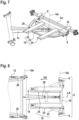
- the transfer element 16 has two transfer sections 24 which extend elongately in the receiving direction AR, between which in the top view according to Fig. 8 the drawbar element 14 is arranged.
- the support section 22 is approximately U-shaped and also carries rollers 35.
Landscapes
- Life Sciences & Earth Sciences (AREA)
- Environmental Sciences (AREA)
- Engineering & Computer Science (AREA)
- Mechanical Engineering (AREA)
- Zoology (AREA)
- Soil Sciences (AREA)
- Transportation (AREA)
- Storage Of Harvested Produce (AREA)
- Agricultural Machines (AREA)
Abstract
Description
- Die Erfindung betrifft eine Ballenaufnahmevorrichtung zur Aufnahme zumindest eines Rundballens von einer Rundballenpresse. Ferner betrifft die Erfindung eine Fahrzeugkombination umfassend die Ballenaufnahmevorrichtung. Die Ballenaufnahmevorrichtung umfasst eine Koppeleinrichtung mit zumindest einem Koppelrahmenelement, das zur ortsfesten Anordnung an einem Maschinenrahmen der Rundballenpresse ausgebildet ist. Ferner umfasst die Ballenaufnahmevorrichtung zumindest ein Deichselelement, das sich in eine Aufnahmerichtung zumindest teilweise zwischen dem Koppelrahmenelement und einem Maschinenrahmen der Ballenvorrichtung erstreckt. Das Deichselelement ist derart an der Koppeleinrichtung gelagert, dass es relativ zum Koppelrahmenelement zumindest um eine Hochachse schwenkbeweglich ist, die wenigstens in einer ersten Stellung der Koppeleinrichtung zu einer Aufstandsfläche der Ballenaufnahmevorrichtung rechtwinklig angeordnet ist.
- Eine derartige Ballenaufnahmevorrichtung ist als Ballenwickler bekannt geworden, der an die Rundballenpresse anzuhängen ist und zur Umwicklung des Rundballens mit einem Hüllmaterial ausgebildet ist. Nachteilig ist die bekannte Ballenaufnahmevorrichtung einerseits, da die Koppeleinrichtung und das Deichselelement nur eine geringfügige Verschwenkung der Rundballenpresse relativ zur Ballenaufnahmevorrichtung zulassen, die im Betrieb den zu erreichenden Kurvenradius begrenzt und regelmäßig zu Kollisionen zwischen der Koppeleinrichtung und der Ballenaufnahmevorrichtung führt. Nachteilig ist die Ballenaufnahmevorrichtung andererseits, da die Koppeleinrichtung und das Deichselelement selbst zur Ermöglichung der geringfügigen Verschwenkung derart spitz zur Hochachse hin zulaufend ausgebildet sind, dass seitlich der Hochachse zwischen der Koppeleinrichtung und dem Deichselelement ein Zwischenraum klafft, in den der Rundballen während seiner Aufnahme von der Rundballenpresse seitlich hinabfallen kann, bevor er den Maschinenrahmen der Ballenaufnahmevorrichtung erreicht hat.
- Die Aufgabe der vorliegenden Erfindung ist die Bereitstellung einer gattungsgemäßen Ballenaufnahmevorrichtung und einer Fahrzeugkombination umfassend die Ballenaufnahmevorrichtung, die die vorbeschriebenen Nachteile vermeiden.
- Erfindungsgemäß weist die Ballenaufnahmevorrichtung ein Überleitelement auf. Das Überleitelement ist an der Koppeleinrichtung gelagert und relativ zum Deichselelement zumindest um die Hochachse schwenkbeweglich. Das Überleitelement erstreckt sich derart in die Aufnahmerichtung, dass das Deichselelement in einer Seitenansicht oder einem Längsschnitt zumindest teilweise zwischen dem Überleitelement und der Aufstandsfläche angeordnet ist.
- Bei der Ballenaufnahmevorrichtung handelt es sich insbesondere um ein mit der der Rundballenpresse zu koppelndes Fahrzeug, das ein eigenes Fahrwerk umfasst. Die Ballenaufnahmevorrichtung bildet bevorzugt eine an die Rundballenpresse, insbesondere eine Presskammer davon, anschließende Aufnahmestrecke für den Rundballen aus. Die Aufnahmestrecke weist aufgrund der genormten Rundballenmaße bevorzugt eine Breite von zumindest 1,20 m und eine Höhe von zumindest 1,20 m aufweist. Die Ballenaufnahmevorrichtung ist vorzugsweise zur Aufnahme und zum Transport mehrerer, insbesondere von zumindest vier, Rundballen ausgebildet. Bevorzugt ist die Ballenaufnahmevorrichtung derart ausgebildet, dass die Rundballen bei ihrer Aufnahme nicht seitlich von ihrer Position in der Presskammer verlagert werden (In-Line-Aufnahme).
- Das Koppelrahmenelement ist insbesondere unbeweglich am Maschinenrahmen der Rundballenpresse zu befestigen, bevorzugt zu verschrauben. Vorzugsweise weist die Ballenaufnahmevorrichtung zwei quer zur Aufnahmerichtung zueinander versetzte Koppelrahmenelemente auf. Bei dem zumindest einen Koppelrahmenelement handelt es sich insbesondere um Unterlenkerfanghaken, die sich in der Landwirtschaft zur Anhängung von Arbeitsmaschinen bewährt haben.
- Die gedachte Hochachse ist in einer Frontansicht der Ballenaufnahmevorrichtung bevorzugt mittig, das heißt innerhalb einer Längsmittelebene, angeordnet. Die Längsmittelebene ist durch die Hochachse und eine in eine Fahrtrichtung, in die die Ballenaufnahmevorrichtung im Betrieb über den Acker zu bewegen ist, verlaufende Längsachse aufgespannt. Die Koppeleinrichtung ist insbesondere spiegelsymmetrisch zur Längsmittelebene ausgebildet. Die Aufnahmerichtung ist bevorzugt rechtwinklig zur Hochachse und/oder zumindest anteilig entgegen der Fahrtrichtung ausgerichtet. Die Aufstandsfläche ist eine gedachte, ebene Fläche, die an das Fahrwerk, bevorzugt Räder, der Ballenaufnahmevorrichtung angrenzt, ohne sie zu schneiden, und sich in die Fahrtrichtung erstreckt und/oder der Bodenfläche des Ackers entspricht, sofern sie eben ist. Die Hochachse verläuft dann vertikal, wenn die Aufstandsfläche sich horizontal erstreckt und die Koppeleinrichtung in der ersten Stellung angeordnet ist. Bevorzugt verläuft die Hochachse in einer bestimmten Stellung der Koppeleinrichtung oder des Deichselelementes um < 90° angewinkelt zur Aufstandsfläche.
- Das Deichselelement verbindet die Koppeleinrichtung mit dem Maschinenrahmen der Ballenaufnahmevorrichtung. Der Maschinenrahmen ist bevorzugt starr zu einer Fahrwerksachse der Ballenaufnahmevorrichtung ausgebildet und/oder weist bevorzugt zumindest zwei seitliche Längsträger auf. Zu dem Maschinenrahmen ist das Deichselelement bevorzugt nicht um eine zur Aufstandsfläche angewinkelte Schwenkachse schwenkbeweglich. Bevorzugt umfasst das Deichselelement einen zentralen, sich entgegen der Aufnahmerichtung vom Maschinenrahmen zur Koppeleinrichtung erstreckenden und auf Zug zu belastenden Träger. Vorzugsweise ist das Deichselelement relativ zum Koppelrahmenelement um ca. 140° schwenkbeweglich um die Hochachse.
- Das Überleitelement ist derart angeordnet, dass zumindest ein Teil von ihm im Betrieb oberhalb zumindest eines Teils des Deichselelementes angeordnet ist. Das Überleitelement reicht von der Koppeleinrichtung aus bevorzugt in die Aufnahmerichtung über die Hochachse hinaus. Das Überleitelement ist insbesondere derart gelagert, dass es relativ zum Koppelrahmenelement nicht um eine zur Aufstandsfläche angewinkelte Achse wie zum Beispiel die Hochachse schwenkbeweglich ist. Das Überleitelement folgt einer Verschwenkung des Maschinenrahmens der Ballenaufnahmevorrichtung relativ zur Rundballenpresse im Betrieb folglich nicht. In der Seitenansicht bzw. im Längsschnitt erstreckt sich das Überleitelement bevorzugt hauptsächlich länglich und verhältnismäßig flach in die Aufnahmerichtung und/oder parallel zur Haupterstreckungsrichtung des Deichselelementes.
- Durch das Überleitelement wird die Aufgabe insofern gelöst, als einerseits die Koppeleinrichtung und/oder das Deichselelement derart schmal bzw. zur Hochachse spitz zulaufend ausgebildet werden können, dass eine im landwirtschaftlichen Betrieb jedenfalls ausreichend weite Verschwenkung des Deichselelementes relativ zur Koppeleinrichtung ermöglicht ist. Andererseits ist ein Hinabfallen des Rundballens in den Zwischenraum durch das ihn überbrückende Überleitelement verhindert. Das Überleitelement ist dabei insbesondere derart ausgebildet, dass eine Kollision damit bei der Verschwenkung ausgeschlossen ist.
- Vorzugsweise ist das Überleitelement derart an der Koppeleinrichtung gelagert, dass es relativ zum Koppelrahmenelement um eine zur Aufstandsfläche parallele Querachse schwenkbeweglich ist. Die gedachte Querachse ist insbesondere ortsfest zum Koppelrahmenelement positioniert. Durch die derart schwenkbewegliche Lagerung des Überleitelementes kann es im Falle einer Änderung einer Steigung und/oder eines Gefälles des Ackers, auf der die Ballenaufnahmevorrichtung betrieben wird, seine Position zu Gunsten einer zuverlässigen Aufnahme des Rundballens anpassen. Die Hochachse und die Querachse sind bevorzugt derart angeordnet, dass sie sich nicht schneiden, das heißt, dass sie voneinander beanstandet sind. Die Hochachse ist im Verhältnis zur Querachse insbesondere in die Aufnahmerichtung versetzt angeordnet.
- Bevorzugt ist das Deichselelement derart an der Koppeleinrichtung gelagert, dass es relativ zum Koppelrahmenelement um eine zur Aufstandsfläche parallele Achse schwenkbeweglich ist. Besonders bevorzugt ist das Deichselelement derart gelagert, dass es relativ zum Koppelrahmenelement, ebenso wie das Überleitelement, um die Querachse schwenkbeweglich ist. Dadurch wird, abgesehen von einer Verschwenkung um die Hochachse, eine Relativbewegung des Überleitelementes und des Deichselelementes im Falle der Änderung der Steigung bzw. des Gefälles vermieden und kann die zur Aufnahme des Rundballens bestmögliche Konfiguration beibehalten werden.
- Vorzugsweise ist das Überleitelement derart an der Koppeleinrichtung gelagert, dass es relativ zum Deichselelement um die Querachse schwenkbeweglich ist. So sind das Überleitelement und das Deichselelement nicht nur relativ zum Koppelrahmenelement, sondern auch relativ zueinander um die Querachse schwenkbeweglich. Dadurch wird das Risiko einer Blockade der Schwenkbewegung des Deichselelementes relativ zum Überleitelement um die Hochachse reduziert und kann das Überleitelement nach oben hin ausweichen. Alternativ sind das Überleitelement und das Deichselelement relativ zueinander nicht schwenkbeweglich um die Querachse gelagert, wodurch sich durch ein einzusparendes Gelenk an anderer Stelle die Ausfallwahrscheinlichkeit reduzieren lässt.
- Die Koppeleinrichtung weist bevorzugt ein Koppelzwischenelement auf, dass am Koppelrahmenelement ausschließlich schwenkbeweglich um die Querachse gelagert ist und am Deichselelement ausschließlich schwenkbeweglich um die Hochachse gelagert ist. Durch das Koppelzwischenelement lassen sich die vorbeschriebenen Schwenkbewegungen durch zwei getrennte und jeweils nur eine Schwenkrichtung erlaubende Gelenke umsetzen, deren Ausfallwahrscheinlichkeit gegenüber der eines komplexen Gelenkes geringer ist. Außerdem kann so mit dem Koppelzwischenelement bereits ein Teil der Koppeleinrichtung zur Aufnahme des Rundballens beitragen. Zur weiteren konstruktiven Vereinfachung ist das Überleitelement vorzugsweise vom Koppelrahmenelement beanstandet am Koppelzwischenelement gelagert.
- Das Überleitelement hat vorzugsweise eine auf die Querachse bezogene radiale Erstreckung, die zumindest in einer Geradeausstellung der Ballenaufnahmevorrichtung zumindest der Hälfte, bevorzugt zwei Drittel, besonders bevorzugt drei Viertel oder mehr, des Abstandes des Maschinenrahmens der Ballenaufnahmevorrichtung von der Querachse entspricht. Bevorzugt ist das Überleitelement derart ausgebildet, dass seine radiale Erstreckung veränderlich ist. Insbesondere zumindest ein dem Maschinenrahmen der Ballenaufnahmevorrichtung zugewandtes Ende des Überleitelementes von einem verstellbaren Verlängerungselement ausgebildet. In der Geradeausstellung der Ballenaufnahmevorrichtung ist das Deichselelement relativ zur Koppeleinrichtung nicht seitlich um die Hochachse verschwenkt und ist die Koppeleinrichtung insbesondere in der ersten Stellung angeordnet. In der Geradeausstellung ordnet sich die Ballenaufnahmevorrichtung im Betrieb dann an, wenn die Ballenaufnahmevorrichtung geradeaus, das heißt ohne Kurvenfahrt, auf dem Acker fortbewegt wird. Durch die radiale Erstreckung des Überleitelementes reicht es bis nah an den Maschinenrahmen der Ballenaufnahmevorrichtung heran und hat es insbesondere eine Länge, die der Länge des Deichselelementes zumindest ähnelt. Hierdurch wird das Risiko eines Herunterfallens des Rundballens zwischen dem Maschinenrahmen und dem Überleitelement minimiert.
- Vorzugsweise ist der Abstand der Hochachse vom Maschinenrahmen der Ballenaufnahmevorrichtung mindestens so groß wie der Abstand der Hochachse von der Querachse. Besonders bevorzugt ist der Abstand der Hochachse vom Maschinenrahmen mindestens doppelt so groß oder gar mindestens fünffach so groß wie der Abstand der Hochachse von der Querachse. Hierdurch ist die Hochachse besonders weit vorne, insbesondere unterhalb der Presskammer der Rundballenpresse anzuordnen, woraus sich mehrere Vorteile ergeben. Zum einen wird hierdurch der Schwenkwinkel des Deichselelementes relativ zur Koppeleinrichtung um die vertikale Achse bei einer vergleichbaren Kurvenfahrt reduziert und eine stabilere Fahrdynamik der Ballenaufnahmevorrichtung erreicht. Zum anderen erlaubt diese Anordnung der Hochachse eine Aufnahme des Rundballens auch noch zumindest bei geringfügigen Kurvenfahrten bzw. Schwenkwinkeln um die Hochachse.
- Vorzugsweise weist die Ballenaufnahmevorrichtung zumindest ein Deichselstellelement auf. Das Deichselstellelement ist zu einer Verschwenkung des Deichselelementes relativ zum Maschinenrahmen der Ballenaufnahmevorrichtung um eine Deichselschwenkachse ausgebildet, die in der Geradeausstellung der Ballenaufnahmevorrichtung zur Querachse parallel angeordnet ist. Bei dem Deichselstellelement handelt es sich insbesondere um einen Hydraulikzylinder. Vorzugsweise weist die Ballenaufnahmevorrichtung zwei Deichselstellelemente auf, die an zwei gegenüberliegenden Seiten des Maschinenrahmens angeordnet sind. Durch das Deichselstellelement lassen sich das Deichselelement und der Maschinenrahmen zumindest zu einem Großteil und insbesondere bis auf die Aufstandsfläche in eine V-Form absenken, woraufhin die Aufnahmerichtung abwärtsgerichtet ist. Im abgesenkten Zustand gelangt der Rundballen vereinfacht, da schwerkraftbedingt, bis zum Maschinenrahmen der Ballenaufnahmevorrichtung. Alternativ ist das Deichselelement starr am Maschinerahmen angeordnet.
- Vorzugsweise weist das Überleitelement einen Abstützabschnitt zur Abstützung des Überleitelementes auf dem Deichselelement auf. Insbesondere liegt das Überleitelement im Betrieb mit dem Abstützabschnitt auf dem Deichselelement auf. Dazu weist der Abstützabschnitt insbesondere eine zur Aufstandsfläche gerichtete Oberfläche auf. Damit ist das Überleitelement bevorzugt im vorderen Bereich an der Koppeleinrichtung, insbesondere am Koppelzwischenelement, und im hinteren Bereich am Deichselelement gelagert. Diese Lagerung ist unabhängig davon vorteilhaft, ob das Überleitelement relativ zum Deichselelement um die Querachse schwenkbeweglich ist. Vorteilhaft ist der Abstützabschnitt insofern, als dadurch die Gewichtskraft eines oberhalb des Deichselelementes auf dem Überleitelement aufliegenden Rundballens nicht alleine über die Koppelleinrichtung abzuleiten ist und das Überleitelement entsprechend massiv auszubilden ist, sondern unmittelbar auf das Deichselelement und insbesondere folglich zumindest zum Teil auf das Fahrwerk der Ballenaufnahmevorrichtung abzuleiten ist.
- Der Abstützabschnitt und/oder seine beschriebene Oberfläche erstrecken/erstreckt sich besonders bevorzugt zumindest im Wesentlichen oder exakt kreisbogenförmig um die Hochachse. Insbesondere wird der Abstützabschnitt von einem Rohr mit einem zu einer Mittellinie symmetrischen Querschnitt ausgebildet, wobei sich die Mittellinie kreisbogenförmig um die Hochachse erstreckt. Der Abstützabschnitt erstreckt sich vorzugsweise um zumindest 90°, insbesondere zumindest um den maximalen Schwenkwinkel des Deichselelementes relativ zum Koppelrahmenelement um die Hochachse.
- In einer vorteilhaften Ausgestaltung der Erfindung ist zwischen dem Deichselelement und dem Überleitelement ein Kugellager oder ein Gleitlager, insbesondere aus Kunststoff angeordnet. Das Gleitlager ist insbesondere als ein zwischen dem Deichselelement und dem Überleitelement, vorzugsweise am Deichselelement, angeordnetes und reibungsminderndes Kunststoffelement, z.B. eine Kunststoffplatte, ausgebildet. Das Kugellager oder ein alternatives Rollen- oder Tonnenlager ist insbesondere dann vorteilhaft, wenn das Überleitelement relativ zum Deichselelement nicht um die Querachse schwenkbeweglich ist. Durch das Kugellager oder das Gleitlager wird die vorteilhafte Kraftübertragung erreicht, ohne dass sich damit ein die Zuverlässigkeit der beiden Aufnahmevorrichtungen gefährdender Verschleiß einstellt.
- Bevorzugt weist das Überleitelement zumindest zwei sich länglich in die Aufnahmerichtung erstreckende Überleitabschnitte auf, zwischen denen sich in einer Draufsicht zumindest in der Geradeausstellung das Deichselelement zumindest teilweise erstreckt. Das Deichselelement erstreckt sich insbesondere länglich in der Längsmittelebene. Die Überleitabschnitte erstrecken sich zur Längsmittelebene versetzt und parallel zu ihr länglich und sind insbesondere spiegelsymmetrisch zur Längsmittelebene ausgebildet. Die Überleitabschnitte erlauben ein ruhiges rollen des Rundballens in die Aufnahmerichtung. Das Überleitelement ist insbesondere einstückig und/oder starr ausgebildet. Hierzu sind die Überleitabschnitte bevorzugt mit dem Abstützabschnitt und insbesondere einem sich parallel zur Querachse erstreckenden Querträger des Überleitelementes verschweißt.
- Die Aufgabe wird weiterhin gelöst durch eine Fahrzeugkombination umfassend die vor- und/oder nachbeschriebe Rundballenpresse und die vor- und/oder nachbeschriebene Ballenaufnahmevorrichtung, die mit der Rundballenpresse gekoppelt ist.
- Dabei ist das zumindest eine Koppelrahmenelement ortsfest an einem Maschinenrahmen der Rundballenpresse angeordnet. Bei der Rundballenpresse handelt es sich vorzugsweise um eine selbstfahrende oder eine im Betrieb an einen Schlepper angehängte Rundballenpresse. Im Falle der Fahrzeugkombination ist das Koppelrahmenelement als vom Maschinenrahmen der Rundballenpresse umfasst zu betrachten. Insbesondere müssen in diesem Fall das Überleitelement und das Deichselelement nicht am selben Bauteil des Maschinenrahmens der Rundballenpresse abgestützt sein.
- Bevorzugt ist das zumindest eine Koppelrahmenelement an einer vom Maschinenrahmen der Rundballenpresse umfassten Fahrwerksachse angeordnet. Die Fahrwerksachse ist ein starres Bauteil, an dem seitlich insbesondere Räder gelagert sind und das sich unterhalb der Presskammer horizontal erstreckt. Durch die Anordnung des zumindest einen Koppelrahmenelementes an der Fahrwerksachse lässt sich die Hochachse in der Praxis besonders weit vorne anordnen, um die vorbeschriebenen Vorteile davon zu erreichen. Die Querachse ist insbesondere hinter der Fahrwerksachse, das heißt in die Aufnahmerichtung zur Fahrwerksachse versetzt, angeordnet. Dadurch lässt sich eine zuverlässige Führung des Rundballens zum Maschinerahmen der Ballenaufnahmevorrichtung erreichen.
- Weitere Einzelheiten und Vorteile der Erfindung sind den nachfolgend beschriebenen, schematisch dargestellten Figuren zu entnehmen; es zeigen:
- Fig. 1
- eine erfindungsgemäße Fahrzeugkombination bei Geradeausfahrt in einer Seitenansicht,
- Fig. 2
- die Fahrzeugkombination gemäß
Fig. 1 in einer Draufsicht, - Fig. 3
- eine Koppeleinrichtung und ein Deichselelement einer erfindungsgemäßen Ballenaufnahmevorrichtung der Fahrzeugkombination gemäß
Fig. 1 in einer perspektivischen Darstellung, - Fig. 4
- in (a) die in
Fig. 3 dargestellten Teile und zusätzliche Elemente der Fahrzeugkombination in einer perspektivischen Darstellung, und in (b) eine weitere Ausführungsform der Koppeleinrichtung und des Deichselelements, - Fig. 5
- die in
Fig. 4 dargestellten Teile in einem Längsschnitt, - Fig. 6
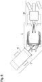
- die Fahrzeugkombination gemäß
Fig. 1 bei Kurvenfahrt in einer Draufsicht, - Fig. 7
- die in
Fig. 4 dargestellten Teile bei Kurvenfahrt in einer perspektivischen Darstellung, - Fig. 8
- eine Koppeleinrichtung, ein Deichselelement, ein Überleitelement und einen Teil eines Maschinenrahmens einer weiteren erfindungsgemäßen Ballenaufnahmevorrichtung in einer Draufsicht.
- Die nachfolgend erläuterten Merkmale können auch einzeln oder in anderen Kombinationen als dargestellt oder beschrieben Gegenstand der Erfindung sein, stets aber zumindest in Kombination mit den Merkmalen des Anspruchs 1. Sofern sinnvoll sind funktional gleichwertige Teile mit identischen Bezugsziffern versehen.
- Die
Fig. 1, 2 und6 zeigen eine erfindungsgemäße Fahrzeugkombination 26 umfassend eine von einem Schlepper 30 gezogene Rundballenpresse 4 und eine mit der Rundballenpresse 4 gekoppelte Ballenaufnahmevorrichtung 2. Die Ballenaufnahmevorrichtung 2 dient zur Aufnahme mehrerer nicht dargestellter Rundballen von der Rundballenpresse 4, um die Rundballen gesammelt ablegen zu können und nicht im Nachhinein jeden Rundballen einzeln auflesen zu müssen. - Die Ballenaufnahmevorrichtung 2 umfasst eine Koppeleinrichtung 6. Die Koppeleinrichtung 6 umfasst zwei Koppelrahmenelemente 8, die ortsfest an einer Fahrzeugachse 32 eines Maschinenrahmens 10 der Rundballenpresse 4 angeordnet sind (vgl.
Fig. 3 und4 ). Ferner umfasst die Koppeleinrichtung 6 ein Koppelzwischenelement 18. Das Koppelzwischenelement 18 ist schwenkbeweglich um eine Querachse HA an den Koppelrahmenelementen 8 gelagert. Am Koppelzwischenelement 18 ist ein Deichselelement 14 schwenkbeweglich um eine Hochachse VA gelagert. Eine Längsachse LA ist insbesondere zumindest in einer Stellung sowohl zur Hochachse VA als auch zur Querachse HA rechtwinklig angeordnet. Das Deichselelement 14 erstreckt sich in eine Aufnahmerichtung AR zwischen dem Koppelzwischenelement 18 und einem Maschinenrahmen 12 der Aufnahmevorrichtung 2. Die Hochachse VA erstreckt sich zumindest in einer ersten Stellung der Koppeleinrichtung 6 rechtwinklig zu einer Aufstandsfläche AF der Ballenaufnahmevorrichtung 2 (vgl.Fig. 1 ). An dem Koppelzwischenelement 18 ist ein Überleitelement 16 schwenkbar um die Querachse HA gelagert. Um die Hochachse VA oder eine dazu parallele Achse ist das Überleitelement 16 relativ zur Koppeleinrichtung 6 unbeweglich (vgl.Fig. 4 und7 ). Das Überleitelement 16 erstreckt sich derart in die Aufnahmerichtung AR, dass das Deichselelement 14 in dem Längsschnitt bzw. der Seitenansicht gemäßFig. 5 zumindest teilweise zwischen dem Überleitelement 16 und der Aufstandsfläche AF angeordnet ist. - Das Überleitelement 16 hat eine auf die Querachse HA bezogene radiale Erstreckung A, die zumindest zwei Drittel eines Abstandes B des Maschinenrahmens 12 der Ballenaufnahmevorrichtung 2 von der Querachse HA entspricht (vgl.
Fig. 5 ). Die radiale Erstreckung ist bei der Ballenaufnahmevorrichtung 2 gemäßFig. 8 durch verschraubte Verlängerungselemente 34 des Überleitelementes 16 variabel. Ferner ist ein Abstand C der Hochachse VA vom Maschinenrahmen 12 der Ballenaufnahmevorrichtung 2 (vgl.Fig. 8 ) mindestens fünffach so groß wie ein Abstand D der Hochachse VA von der Querachse (vgl.Fig. 5 ). Die Ballenaufnahmevorrichtung 2 weist zwei Deichselstellelemente 20 auf, die zu einer Verschwenkung des Deichselelementes 14 relativ zum Maschinenrahmen 12 der Ballenaufnahmevorrichtung 2 um eine Deichselschwenkachse DA ausgebildet sind, die in der mit denFig. 1 und 2 dargestellten Geradeausstellung der Ballenaufnahmevorrichtung 2 parallel zur Querachse HA verläuft (vgl.Fig. 8 ). - Das Überleitelement 16 weist einen sich kreisförmig um die Hochachse VA erstreckenden Abstützabschnitt 22 auf, der in den
Fig. 4a ,7 und 8 vereinfacht aus zueinander angewinkelten, geraden Elementen bestehend dargestellt ist. Der Abstützabschnitt 22 dient zur Abstützung des Überleitelementes 16 auf dem Deichselelement 14. Dazwischen ist an dem Deichselelement 14 ein Gleitlager 28 aus Kunststoff angeordnet, das die Verschwenkung des Deichselelementes 14 relativ zum Überleitelement 16 um die Hochachse VA erlaubt (vgl.Fig. 7 ). Neben dem Abstützabschnitt 22 weist das Überleitelement 16 zwei sich länglich in die Aufnahmerichtung AR erstreckende Überleitabschnitte 24 auf, zwischen denen in der Draufsicht gemäßFig. 8 das Deichselelement 14 angeordnet ist. - Bei dem Überleielement 16 der Ausführungsform der
Fig. 4b ist der Abstützabschnitt 22 demgegenüber etwa u- förmig ausgebildet und trägt zudem Rollen 35. Dadurch kann der aus der Rundballenpresse 4 ausgeworfene Rundballen mit weniger Reibung auf dem anfänglich sehr steilen Überleitelement 16 schnell und zuverlässig zur Ballenaufnahmevorrichtung 2 rollen.
Claims (15)
- Ballenaufnahmevorrichtung (2) zur Aufnahme zumindest eines Rundballens von einer Rundballenpresse (4), umfassend eine Koppeleinrichtung (6) mit zumindest einem Koppelrahmenelement (8) zur ortsfesten Anordnung an einem Maschinenrahmen (10) der Rundballenpresse (4) und zumindest ein sich in eine Aufnahmerichtung (AR) zumindest teilweise zwischen dem Koppelrahmenelement (8) und einem Maschinenrahmen (12) der Ballenaufnahmevorrichtung (2) erstreckendes und derart an der Koppeleinrichtung (6) gelagertes Deichselelement (14), dass es relativ zum Koppelrahmenelement (8) zumindest um eine wenigstens in einer ersten Stellung der Koppeleinrichtung (6) zu einer Aufstandsfläche (AF) der Ballenaufnahmevorrichtung (2) rechtwinklige Hochachse (VA) schwenkbeweglich ist, gekennzeichnet durch ein an der Koppeleinrichtung (6) gelagertes, relativ zum Deichselelement (14) zumindest um die Hochachse (VA) schwenkbewegliches und sich derart in die Aufnahmerichtung (AR) erstreckendes Überleitelement (16), dass das Deichselelement (14) in einer Seitenansicht zumindest teilweise zwischen dem Überleitelement (16) und der Aufstandsfläche (AF) angeordnet ist.
- Ballenaufnahmevorrichtung nach Anspruch 1, dadurch gekennzeichnet, dass das Überleitelement (16) derart an der Koppeleinrichtung (6) gelagert ist, dass es relativ zum Koppelrahmenelement (8) um eine zur Aufstandsfläche (AF) parallele Querachse (HA) schwenkbeweglich ist.
- Ballenaufnahmevorrichtung nach einem der vorhergehenden Ansprüche, dadurch gekennzeichnet, dass das Deichselelement (14) derart an der Koppeleinrichtung (6) gelagert ist, dass es relativ zum Koppelrahmenelement (8) um die Querachse (HA) schwenkbeweglich ist.
- Ballenaufnahmevorrichtung nach einem der vorhergehenden Ansprüche, dadurch gekennzeichnet, dass das Überleitelement (16) derart an der Koppeleinrichtung (6) gelagert ist, dass es relativ zum Deichselelement (14) um die Querachse (HA) schwenkbeweglich ist.
- Ballenaufnahmevorrichtung nach einem der vorhergehenden Ansprüche, dadurch gekennzeichnet, dass die Koppeleinrichtung (6) ein Koppelzwischenelement (18) aufweist, das am Koppelrahmenelement (8) ausschließlich schwenkbeweglich um die Querachse (HA) gelagert ist und am Deichselelement (14) ausschließlich schwenkbeweglich um die Hochachse (VA) gelagert ist.
- Ballenaufnahmevorrichtung nach einem der vorhergehenden Ansprüche, dadurch gekennzeichnet, dass das Überleitelement (16) vom Koppelrahmenelement (8) beabstandet am Koppelzwischenelement (18) gelagert ist.
- Ballenaufnahmevorrichtung nach einem der vorhergehenden Ansprüche, dadurch gekennzeichnet, dass das Überleitelement (16) eine auf die Querachse (HA) bezogene radiale Erstreckung (A) hat, die zumindest in einer Geradeausstellung der Ballenaufnahmevorrichtung zumindest der Hälfte, bevorzugt zumindest zwei Drittel, besonders bevorzugt zumindest drei Viertel, eines Abstandes (B) des Maschinenrahmens (12) der Ballenaufnahmevorrichtung (2) von der Querachse (HA) entspricht.
- Ballenaufnahmevorrichtung nach einem der vorhergehenden Ansprüche, dadurch gekennzeichnet, dass ein Abstand (C) der Hochachse (VA) vom Maschinenrahmen (12) der Ballenaufnahmevorrichtung (2) mindestens so groß ist, bevorzugt mindestens doppelt so groß ist, besonders bevorzugt mindestens fünffach so groß ist, wie ein Abstand (D) der Hochachse (VA) von der Querachse (HA).
- Ballenaufnahmevorrichtung nach einem der vorhergehenden Ansprüche, gekennzeichnet durch zumindest ein Deichselstellelement (20), das zu einer Verschwenkung des Deichselelementes (14) relativ zum Maschinenrahmen (12) der Ballenaufnahmevorrichtung (2) um eine in einer/der Geradeausstellung der Ballenaufnahmevorrichtung zur Querachse (HA) parallele Deichselschwenkachse (DA) ausgebildet ist.
- Ballenaufnahmevorrichtung nach einem der vorhergehenden Ansprüche, dadurch gekennzeichnet, dass das Überleitelement (16) einen Abstützabschnitt (22) zur Abstützung des Überleitelementes (16) auf dem Deichselelement (14) aufweist.
- Ballenaufnahmevorrichtung nach einem der vorhergehenden Ansprüche, dadurch gekennzeichnet, dass der Abstützabschnitt (22) sich kreisbogenförmig um die Hochachse (VA) erstreckt.
- Ballenaufnahmevorrichtung nach einem der vorhergehenden Ansprüche, dadurch gekennzeichnet, dass zwischen dem Deichselelement (14) und dem Überleitelement (16) ein Kugellager oder ein Gleitlager (28), insbesondere aus Kunststoff, angeordnet ist.
- Ballenaufnahmevorrichtung nach einem der vorhergehenden Ansprüche, dadurch gekennzeichnet, dass das Überleitelement (16) zumindest zwei sich länglich in die Aufnahmerichtung (AR) erstreckende Überleitabschnitte (24) aufweist, zwischen denen sich in einer Draufsicht zumindest in einer/der Geradeausstellung der Ballenaufnahmevorrichtung das Deichselelement (14) zumindest teilweise erstreckt.
- Fahrzeugkombination (26) umfassend eine Rundballenpresse (4) und eine mit der Rundballenpresse (4) gekoppelte Ballenaufnahmevorrichtung (2) nach einem der vorhergehenden Ansprüche, wobei das zumindest eine Koppelrahmenelement (8) ortsfest an einem Maschinenrahmen (10) der Rundballenpresse (4) angeordnet ist.
- Fahrzeugkombination nach einem der vorhergehenden Ansprüche, dadurch gekennzeichnet, dass das zumindest eine Koppelrahmenelement (8) an einer vom Maschinenrahmen (10) der Rundballenpresse (4) umfassten Fahrwerksachse (32) angeordnet ist.
Applications Claiming Priority (1)
| Application Number | Priority Date | Filing Date | Title |
|---|---|---|---|
| DE102022115781.4A DE102022115781A1 (de) | 2022-06-24 | 2022-06-24 | Ballenaufnahmevorrichtung zur Aufnahme von Rundballen einer Rundballenpresse |
Publications (1)
| Publication Number | Publication Date |
|---|---|
| EP4295663A1 true EP4295663A1 (de) | 2023-12-27 |
Family
ID=86942821
Family Applications (1)
| Application Number | Title | Priority Date | Filing Date |
|---|---|---|---|
| EP23181072.2A Pending EP4295663A1 (de) | 2022-06-24 | 2023-06-22 | Ballenaufnahmevorrichtung zur aufnahme von rundballen einer rundballenpresse |
Country Status (3)
| Country | Link |
|---|---|
| US (1) | US20230413707A1 (de) |
| EP (1) | EP4295663A1 (de) |
| DE (1) | DE102022115781A1 (de) |
Citations (5)
| Publication number | Priority date | Publication date | Assignee | Title |
|---|---|---|---|---|
| US3480163A (en) * | 1968-02-23 | 1969-11-25 | Int Harvester Co | Steering arm for bale thrower |
| DE3304166C2 (de) * | 1983-02-08 | 1986-05-15 | Busatis-Werke GmbH u. Co KG, 5630 Remscheid | Rundballenübernahme- und Transportfahrzeug |
| EP0404668A1 (de) * | 1989-06-19 | 1990-12-27 | Jean-François Bregeron | Ballensammlergerät |
| CA2165111A1 (en) * | 1995-12-13 | 1997-06-14 | Richard Kohnen | Bale-accumulating trailer |
| US20050188862A1 (en) * | 2004-02-28 | 2005-09-01 | Hoover Larry L. | Torsion spring activated round bale kicker |
Family Cites Families (3)
| Publication number | Priority date | Publication date | Assignee | Title |
|---|---|---|---|---|
| US4815266A (en) * | 1987-09-30 | 1989-03-28 | Hesston Corporation | Continuous round baler with accumulating trailer |
| US6607342B1 (en) * | 2001-12-28 | 2003-08-19 | Michael W. Tolzin | Bale transporting apparatus |
| DE102019201337A1 (de) * | 2019-02-01 | 2020-08-06 | Deere & Company | Landwirtschaftliches Arbeitsgerät, Deichselvorrichtung und Zugfahrzeug-Arbeitsgerät-Kombination |
-
2022
- 2022-06-24 DE DE102022115781.4A patent/DE102022115781A1/de active Pending
-
2023
- 2023-06-22 EP EP23181072.2A patent/EP4295663A1/de active Pending
- 2023-06-23 US US18/340,634 patent/US20230413707A1/en active Pending
Patent Citations (5)
| Publication number | Priority date | Publication date | Assignee | Title |
|---|---|---|---|---|
| US3480163A (en) * | 1968-02-23 | 1969-11-25 | Int Harvester Co | Steering arm for bale thrower |
| DE3304166C2 (de) * | 1983-02-08 | 1986-05-15 | Busatis-Werke GmbH u. Co KG, 5630 Remscheid | Rundballenübernahme- und Transportfahrzeug |
| EP0404668A1 (de) * | 1989-06-19 | 1990-12-27 | Jean-François Bregeron | Ballensammlergerät |
| CA2165111A1 (en) * | 1995-12-13 | 1997-06-14 | Richard Kohnen | Bale-accumulating trailer |
| US20050188862A1 (en) * | 2004-02-28 | 2005-09-01 | Hoover Larry L. | Torsion spring activated round bale kicker |
Also Published As
| Publication number | Publication date |
|---|---|
| DE102022115781A1 (de) | 2024-01-04 |
| US20230413707A1 (en) | 2023-12-28 |
Similar Documents
| Publication | Publication Date | Title |
|---|---|---|
| EP0543145B1 (de) | Rundballenwickelgerät | |
| EP1210862B1 (de) | Vorrichtung zum Pressen und Umwickeln von Rundballen | |
| DE2623209A1 (de) | Erbsen-erntemaschine | |
| DE2530249A1 (de) | Wickelballenpresse | |
| EP0934690A1 (de) | Schwadeinrichtung | |
| DE2851117A1 (de) | Sammel- und ablegevorrichtung fuer pressballen | |
| EP1726204B1 (de) | Vorrichtung zum Pressen und Umhüllen von Rundballen | |
| EP3788864B1 (de) | Aufnahmevorrichtung für eine landwirtschaftliche arbeitsmaschine, landwirtschaftliche arbeitsmaschine und arbeitszug mit einer solchen landwirtschaftlichen arbeitsmaschine | |
| DE102022115781A1 (de) | Ballenaufnahmevorrichtung zur Aufnahme von Rundballen einer Rundballenpresse | |
| EP4245121B1 (de) | Abladekippvorrichtung für rundballen | |
| DE10334680B4 (de) | Vorrichtung zum Umhüllen oder Verpacken von insbesondere landwirtschaftlichen Erntegutballen | |
| EP4466977B1 (de) | Ballenpresse für landwirtschaftliches erntegut | |
| EP1588601B1 (de) | Erntemaschine mit einer Austrageinrichtung | |
| EP4176705A1 (de) | Rundballenpresse mit einer vorrichtung zum klemmen eines ballens | |
| EP4491009B1 (de) | Abladekippvorrichtung und ballenpresse oder wickler | |
| EP0959661B1 (de) | Verfahren zur ausgabe von halmgutballen und vorrichtung zur durchführung des verfahrens | |
| EP1738634A1 (de) | Erntegutaufnahmeeinrichtung und Erntemaschine | |
| DE102022105847A1 (de) | Schwadaufnehmer mit drittem Stützrad | |
| AT520228A1 (de) | Ballentransportwagen | |
| DE3304166C2 (de) | Rundballenübernahme- und Transportfahrzeug | |
| EP4417037B1 (de) | Schneidwerk für halmförmiges landwirtschaftliches erntegut | |
| WO2016118986A1 (de) | Vorrichtung zum laden und zum transport von rundballen | |
| DE102016114379B4 (de) | Ballensammelwagen zum Aufsammeln und Transportieren von Rundballen | |
| DE2553437A1 (de) | Vorrichtung zur handhabung von heu- oder futterballen | |
| EP4442106A1 (de) | Ballensammelwagen zum transportieren eines ballens, arbeitszug umfassend eine rundballenpresse und einen solchen ballensammelwagen, sowie verfahren zum entladen von ballen aus einer rundballenpresse eines solchen arbeitszuges |
Legal Events
| Date | Code | Title | Description |
|---|---|---|---|
| PUAI | Public reference made under article 153(3) epc to a published international application that has entered the european phase |
Free format text: ORIGINAL CODE: 0009012 |
|
| STAA | Information on the status of an ep patent application or granted ep patent |
Free format text: STATUS: THE APPLICATION HAS BEEN PUBLISHED |
|
| AK | Designated contracting states |
Kind code of ref document: A1 Designated state(s): AL AT BE BG CH CY CZ DE DK EE ES FI FR GB GR HR HU IE IS IT LI LT LU LV MC ME MK MT NL NO PL PT RO RS SE SI SK SM TR |
|
| STAA | Information on the status of an ep patent application or granted ep patent |
Free format text: STATUS: REQUEST FOR EXAMINATION WAS MADE |
|
| 17P | Request for examination filed |
Effective date: 20240423 |
|
| RBV | Designated contracting states (corrected) |
Designated state(s): AL AT BE BG CH CY CZ DE DK EE ES FI FR GB GR HR HU IE IS IT LI LT LU LV MC ME MK MT NL NO PL PT RO RS SE SI SK SM TR |
|
| P01 | Opt-out of the competence of the unified patent court (upc) registered |
Free format text: CASE NUMBER: APP_64190/2024 Effective date: 20241204 |