EP4294253B1 - Vorrichtung und verfahren zur bestimmung des brechungsfehlers eines auges - Google Patents
Vorrichtung und verfahren zur bestimmung des brechungsfehlers eines auges Download PDFInfo
- Publication number
- EP4294253B1 EP4294253B1 EP22706054.8A EP22706054A EP4294253B1 EP 4294253 B1 EP4294253 B1 EP 4294253B1 EP 22706054 A EP22706054 A EP 22706054A EP 4294253 B1 EP4294253 B1 EP 4294253B1
- Authority
- EP
- European Patent Office
- Prior art keywords
- eye
- optical power
- refractive error
- images
- camera
- Prior art date
- Legal status (The legal status is an assumption and is not a legal conclusion. Google has not performed a legal analysis and makes no representation as to the accuracy of the status listed.)
- Active
Links
Images

Classifications
-
- A—HUMAN NECESSITIES
- A61—MEDICAL OR VETERINARY SCIENCE; HYGIENE
- A61B—DIAGNOSIS; SURGERY; IDENTIFICATION
- A61B3/00—Apparatus for testing the eyes; Instruments for examining the eyes
- A61B3/10—Objective types, i.e. instruments for examining the eyes independent of the patients' perceptions or reactions
- A61B3/103—Objective types, i.e. instruments for examining the eyes independent of the patients' perceptions or reactions for determining refraction, e.g. refractometers, skiascopes
-
- A—HUMAN NECESSITIES
- A61—MEDICAL OR VETERINARY SCIENCE; HYGIENE
- A61B—DIAGNOSIS; SURGERY; IDENTIFICATION
- A61B3/00—Apparatus for testing the eyes; Instruments for examining the eyes
- A61B3/0008—Apparatus for testing the eyes; Instruments for examining the eyes provided with illuminating means
-
- A—HUMAN NECESSITIES
- A61—MEDICAL OR VETERINARY SCIENCE; HYGIENE
- A61B—DIAGNOSIS; SURGERY; IDENTIFICATION
- A61B3/00—Apparatus for testing the eyes; Instruments for examining the eyes
- A61B3/10—Objective types, i.e. instruments for examining the eyes independent of the patients' perceptions or reactions
- A61B3/14—Arrangements specially adapted for eye photography
Definitions
- the present application relates to apparatuses and methods for determining the refractive error of an eye as well as to kits and computer programs associated therewith.
- the refractive error of an eye is usually given in terms of sphere, also referred to as spherical power, as defined in 11.2 of DIN EN ISO 13666:2013-10, cylinder, also referred to as cylindrical power, as defined under 12.5 of DIN EN ISO 13666:2013-10 and axis, more precisely cylinder axis, as defined under 12.6 of DIN EN ISO 13666:2013-10.
- sphere also referred to as spherical power
- cylindrical power as defined under 12.5 of DIN EN ISO 13666:2013-10
- axis more precisely cylinder axis, as defined under 12.6 of DIN EN ISO 13666:2013-10.
- a determination of the refractive error may be a subjective refractive error determination or objective refractive error determination.
- Methods for subjective refractive error determination are based on a (subjective) feedback of an examined person regarding his or her visual perception. An example is a measurement on the basis of eye charts with small and smaller symbols, letters, numbers or the like, where the person gives feedback which numbers, letters or symbols he or she can recognize. Lenses may then be placed in front of the eye of the person, and the person may give feedback with which lenses the best visual perception is obtained.
- An example for apparatuses allowing subjective refractive error determinations are phoropters. Methods and apparatuses for objective refractive error determination do not need such a feedback of the examined person regarding his or her visual perception.
- Examples of apparatuses for objective refractive error determination are Hartmann-Shack-based aberrometers, as for example described in G. Colicchia and H. Wiesner, Physics Education, Volume 41, No. 4 .
- Such aberrometers are comparatively complex and therefore are costly apparatuses which require a camera and lenslet array for sensing wavefronts.
- the measurement range of such aberrometers is limited by the parameters of the lenslet array and is inversely proportional to the accuracy, i.e. a higher measurement range typically will result in lower accuracy.
- WO 2020 / 249 679 A1 discloses an apparatus for determining the refractive error of an eye using a smartphone.
- An image of a retina of the eye is captured and convolved with point spread functions corresponding to different defocus values.
- Point spread functions are determined based on images using complex mathematical operations like a neural network or using convolutions and deconvolutions.
- the refractive error is the determined based on the defocus of the best fitted point spread function.
- US 2005 / 030 477 A1 uses wavefront sensing and laser illumination to determine a refractive error of an eye.
- EP 2 026 693 B1 discloses a subjective refraction error determination method.
- the dependent claims furthermore define a corresponding computer program, a kit for a mobile computer device and a method for producing a lens for spectacle glasses.
- An apparatus for determining a refractive error of an eye comprising:
- the apparatus comprises a computing device configured to calculate the refractive error based on a series of images of light from the eye captured by the camera with varying optical power using the series of images directly as at least approximate point spread functions.
- the point spread function of the optical path from the eye to the camera is an intensity distribution resulting from the eye being illuminated at a single spot.
- no point illumination device but a more extended illumination device may be used, in which case the intensity distributions of the images represent approximate point spread function.
- the computing device for calculating the refractive error, is configured to determine a modulation transfer area as a function of meridian angle and optical power in an angle range from 0° to 180° based on the series of images, and to calculate the refractive error based on the modulation transfer area as a function of angle and optical power.
- the apparatus may calculate the refractive error, for example in terms of sphere, cylinder and axis, based on a single measurement series with varying optical power. As any measurement, the measurement may be repeated to increase accuracy, but a single measurement is sufficient.
- the series of images of light from the eye captured is used as a point spread function, so no image of the retina needs to be captured.
- image of light from the eye indicates this, i.e. the images do not have the purpose of capturing structures of the eye itself, but have the purpose of capturing a light intensity distribution of light coming from the eye, e.g. in response to illumination with a light source internal or external to the apparatus as explained further below.
- the optical power changing device may include a variable focus optic.
- a variable focus optic generally is an optical device the focal length of which may varied.
- Such a variable focus optic may for example comprise one or more lenses, a focal length of which may be varied.
- Such lenses may for example include a lens with electrically variable focus as discussed in K. Asatryan et al., Optics Express, Volume 18, No. 13 , liquid lenses, or an optic with two or more lenses, some of which are movable with respect to other lenses.
- Other examples include lens- or mirror-based Badal systems ( D. A. Atchison, A.
- an optical power changing device causes axial movement of fixed focal length lenses within the system, or of the detector device.
- a range through which the optical power of the optical power changing device can be varied corresponds to a measurement range of the apparatus.
- the optical power setting device may be implemented in software on the computing device to computationally vary the optical power.
- the computing device may control the optical power changing device to vary the optical power, while the controlling the camera to capture images of light from the eye for each optical power setting to obtain the series of images.
- the computing device is a mobile computer device like a smartphone and a tablet computer
- the camera may be a camera of the smartphone or tablet computer.
- the apparatus may be implemented at comparatively low costs by using an existing smartphone or tablet computer.
- the optical power changing device may be an autofocus device of the camera, for example camera of the mobile computer device. This may further decrease implementation costs.
- a separate optical power changing device may be provided to increase a measurement range compared to an autofocus.
- the optical power changing device may be implemented in software on the computing device to computationally change the optical power.
- a computational implementation of an optical power changing device may for example be implemented similar to the above mentioned WO 2020 / 249679 A1 , with the difference that no retinal image is convolved with point spread functions representing different optical power (defocus values), but the image used as an at least approximate point spread function is convolved with point spread functions representing different optical powers.
- the apparatus may further include an illumination device for creating a focal spot on the retina of the eye for the measurement, which, when back-propagated, produces point spread functions (of the point corresponding to the focal spot) for the varying optical powers on the camera.
- an illumination device for creating a focal spot on the retina of the eye for the measurement, which, when back-propagated, produces point spread functions (of the point corresponding to the focal spot) for the varying optical powers on the camera.
- a non-point illumination device like a light emitting diode, LED
- the detector device measures essentially a superposition of all point spread functions of points of the light on the eye. This, may be seen as an approximation of the point spread function and may also be used for measurements as described herein. Therefore, a point illumination device like a focused laser is not required, but may be used for more precise measurements.
- the illumination device uses infrared light, in particular an infrared laser. In this way, the person examined does not notice the light used for the measurement.
- an illumination device external to the apparatus may be used, which may be a point illumination device like a laser or an approximation of a point source like a light-emitting diode.
- a beam diameter of the illumination device may be below 2mm, for example below 1.5mm, preferably below 1mm.
- an optical power setting where the point spread function is sharpest may be determined. This is equivalent to determining the maximum of an area (integral) of the modulation transfer function (MTF) for the three meridians.
- the modulation transfer function essentially corresponds to the absolute value of the optical transfer function (OTF), which is defined as the Fourier transfer of form of the point spread function
- P 0 , P 45 , and P 90 being the respective optical power settings in Diopters (D) of the optical power provided by the optical power changing device or computationally varied optical power in the pupil plane of the eye in terms of a deviation from a 0 setting for three meridians of 0°, 45° and 90°, respectively, where the point spread function is sharpest (or the MTF area is at its maximum)
- J 45 P 45 ⁇ M
- the cylinder J may be calculated according to and the axis ⁇ may be calculated according to
- the sphere corresponds to M.
- sphere, cylinder and axis may be calculated.
- the maximum area of the modulation transfer function depending on optical power setting is calculated for a plurality of meridians over at least 180° with a step size smaller than 20°, preferably smaller than 10°, more preferably 5° or smaller, for example 1°. Then, the refractive error is calculated based on the area of the modulation transfer function as a function of optical power setting and angle.
- a corresponding method is also provided, which includes capturing a series of images of an eye with varying optical power, and calculating the refractive error based on the series of images, as explained above for the first and second aspect.
- the method may further include illuminating the eye with an illumination device as discussed above.
- the above explanations made for the apparatus also apply to the method, for example the different ways of calculating the refractive error based on the images.
- the method may be implemented in form of a computer program, for example in form of an application (app) for a mobile computer device like a smartphone or a tablet.
- the computer program may be provided on a tangible storage medium.
- the computer program may, when executed on a computing device, cause the computing device to cause execution of the method as discussed above, for example by controlling an apparatus as discussed above and performing calculations for refractive error determination.
- the computer program may be included in a kit for a mobile computer device, where the kit, in addition to the computer program, may include a hardware module to be connected to the smart phone.
- the hardware module may include one or more hardware elements from the group consisting of an illumination device as mentioned above and an optical power changing device as mentioned above, and may also include further optical elements like lenses or mirrors.
- the refractive error determined by the above apparatuses, methods, computer programs and kits, may then be used for producing lenses based on the refractive error, i.e. lenses to correctly refractive error of the eye.
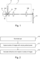
- Fig. 1 is a diagram illustrating an apparatus for determining a refractive error of an eye 10 having optical properties represented by a lens 10A according to an embodiment.
- a dedicated apparatus may be provided including for example elements of hardware unit 11, a camera corresponding to camera 13 and a computing device having processing capabilities using processors, memories and the like, which in case of Fig. 1 is performed by mobile computer device 12.
- Hardware unit 11 includes an infrared laser 17 as an illumination device. Light from infrared laser 17 is reflected by a semitransparent mirror 16 through lens 10A into eye 10.
- Infrared laser 17 may be regarded as approximately being a point illumination device.
- other illumination devices for example light-emitting diodes, may be used.
- variable focus optic 15 symbolized by a focus-adjustable lens in Fig. 1 and an optics arrangement including lenses 14A and 14B.
- Variable focus optic 15 is a simple example for an optical power changing device and may be implemented as explained above, for example using an adjustable liquid lens or any of the other possibilities mentioned above, including an arrangement of several lenses or other optical elements as well as moving lenses or moving a camera 13.
- the placement of variable focus optic 13 is also only an example, and other placements may be used, for example a placement between lens 14B and camera 13, or a placement between lenses 14A and 14B.
- variable focus optic 15 A setting of variable focus optic 15 will also be referred to as defocus in the following.
- variable focus optic 15 may be omitted, and an autofocus of camera 13 may be controlled to perform the function of an optical power changing device, as explained above and further below.
- a measurement range (a range from maximum negative defocus to maximum positive defocus) may be extended.
- other optical power changing devices that a variable focus optic may be used.
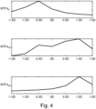
- step 20 the method includes illuminating an eye.
- this illumination is performed by infrared laser 17 via semitransparent mirror 16.
- the method comprises capturing a series of images with varying optical power.
- computing device 12 controls variable focus lens 15 to provide different defocus settings, corresponding to varying optical power, and controls camera 13 to capture an image for each defocus setting, thus resulting in a series of images.
- the method comprises calculating the refractive error, for example in terms of sphere, cylinder and axis, based on the series of images. Each image essentially corresponds to the point spread function or at least approximate point spread function for the respective defocus setting, and the refractive error is calculated essentially based on said point spread functions.
- Fig. 3A shows example images representing the point spread function captured with camera 13 of Fig. 1 for defocus settings from -1.5 diopters (D) to 1.5 D in steps of 0.5 D.
- the step size of 0.5 D is only an example, and to increase accuracy also a smaller step size, for example 0.1 D, may be used.
- the intensity in the image e.g. greyscale value, mean RGB value
- the "best focus" i.e. a defocus setting where the point spread function is sharpest, is determined for three different meridians, i.e. three different directions in the images of Fig 3A .
- meridians of 0°, 45° and 90° are used, where the directions are shown at 30 in Fig. 3 .
- other angles may be used, with corresponding modifications to the calculations set forth below, in some embodiments, the best focus may be found by evaluating the images directly, i.e. by evaluating the shape of point spread function curves in three directions.
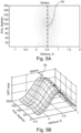
- Fig. 3B illustrates intensities for the images of Fig. 3A along lines having a 0° angle (top row), 45° angle
- the modulation transfer function may be calculated for the three meridians, and an area (integral) of the modulation transfer function may be determined.
- the measurement may be repeated, to increase accuracy through a plurality of measurements by statistics, as essentially possible for all measurements.
- the angle may be varied slightly. For example, for finding the best focus for 45°, meridians in a range around 45°, for example from 43° to 47°, may be evaluated, and the average best focus settings then may be used as for all these angles then may be used as the best focus setting for 45°. This was done for the MTFa functions shown in Fig. 4 .
- J 45 P 45 ⁇ M
- chromatic shift from 555nm to 780nm would be around 0.8 D. Then, for calculating the refraction values, 0.8 D should be subtracted from M, P 0 , and P 45 as used in the equations above.
- the modulation transfer area MTFa is calculated for each optical power setting, for example defocus settings as shown in Fig. 3 .
- the modulation transfer focus area is not calculated only for three meridians, that over 180° in a certain step size, for example 10°, 5° or 1°, even if other step sizes or varying step sizes may also be used.
- step size for example 10°, 5° or 1°
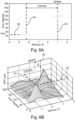
- the modulation transfer area MTFa is determined as a function of defocus setting and angle.
- This function may be represented as an image, where the modulation transfer function area corresponds to the intensity (e.g. greyscale value, brightness value or the like) and the x- and y- coordinates in the image represent defocus setting and angle or as a 3D Plot.
- Figs. 5A and 6A an image representation is given, whereas in Figs. 5B and 6B , a representation as a 3D Plot is used.
- a more dense hatching represents a higher intensity.
- the defocus is on the x-axis
- the angle of the Meridian measured is on the y-axis
- the intensity of the image represents the area of the modulation transfer function.
- the values of sphere, cylinder and axis may then be found using simple image processing.
- the maximum area is always at the same defocus, indicated by a line 50 in Fig. 5 .
- the sphere value would be 0.5.
- This value may for example also be found by calculating a mean area across all meridians (angles).
- a significant value of astigmatism for example more than 0.25 D, two peaks will be found in the mean modulation transfer function overall angles depending on the focus. This corresponds to two peaks found in Fig. 6 .
- the sphere value then is at the defocus value corresponding to the peak at a higher defocus, in case of Fig. 6 at 1 D, as indicated by a line 60.
- the cylinder value corresponds to the difference in defocus between the two peaks, i.e. the difference on the defocus, x, axis between line 60 and 61 of Fig. 6 .
- the axis value corresponds to the position of the second peak (with lower defocus) on the y, angle, axis as indicated by a line 62. In this way, by evaluating the modulation transfer area as a function of angle and defocus, sphere, cylinder and axis may be found.
- the thus determined refractive error may then be used for producing a lens for spectacle glasses based on the refractive error to correct the refractive error.
- the determined refractive error may be transmitted to a lens manufacturer, for example by using an Internet connection established by mobile computer device 13 of Fig. 3 .
Landscapes
- Life Sciences & Earth Sciences (AREA)
- Health & Medical Sciences (AREA)
- Medical Informatics (AREA)
- Biophysics (AREA)
- Ophthalmology & Optometry (AREA)
- Engineering & Computer Science (AREA)
- Biomedical Technology (AREA)
- Heart & Thoracic Surgery (AREA)
- Physics & Mathematics (AREA)
- Molecular Biology (AREA)
- Surgery (AREA)
- Animal Behavior & Ethology (AREA)
- General Health & Medical Sciences (AREA)
- Public Health (AREA)
- Veterinary Medicine (AREA)
- Eye Examination Apparatus (AREA)
Claims (9)
- Gerät zum Bestimmen eines Brechungsfehlers eines Auges (10), umfassend:eine Kamera (13), dazu konfiguriert, ein Bild des Lichts von dem Auge aufzunehmen, undeine Vorrichtung zum Ändern der optischen Leistung (15), dazu konfiguriert, eine optische Leistung eines Lichtwegs von dem Auge (10) zu der Kamera (13) zu variieren,eine Rechenvorrichtung, dazu konfiguriert, auf der Grundlage einer Bildserie von Licht aus dem Auge (10), die von der Kamera (13) mit unterschiedlicher optischer Leistung aufgenommen worden ist, den Brechungsfehler des Auges (10) zu berechnen, wobei die Bildserie direkt als mindestens angenäherte Punktspreizfunktionen verwendet wird,wobei die Punktspreizfunktion eine Intensitätsverteilung ist, die sich aus der Beleuchtung des Auges an einem einzigen Punkt ergibt, und dadurch gekennzeichnet, dass die Rechenvorrichtung zum Berechnen des Brechungsfehlers dazu konfiguriert ist, eine Modulationsübertragungsfläche als eine Funktion des Meridianwinkels und der optischen Leistung in einem Winkelbereich von 0° bis 180° basierend auf der Bildserie zu bestimmen und den Brechungsfehler basierend auf der Modulationsübertragungsfläche als Funktion des Winkels und der optischen Leistung zu berechnen.
- Gerät nach Anspruch 1, dadurch gekennzeichnet, dass die Rechenvorrichtung eine mobile Computervorrichtung einschließlich der Kamera (13) ist.
- Gerät nach Anspruch 1 oder 2, dadurch gekennzeichnet, dass die Vorrichtung zum Ändern der optischen Leistung eine Autofokusvorrichtung der Kamera (13) einschließt.
- Gerät nach einem der Ansprüche 1 bis 3, dadurch gekennzeichnet, dass die Vorrichtung zum Ändern der optischen Leistung als Software auf der Rechenvorrichtung (12) implementiert ist, um die optische Leistung rechnerisch zu variieren.
- Gerät nach einem der Ansprüche 1 bis 4, dadurch gekennzeichnet, dass es ferner eine Punktbeleuchtungsvorrichtung (17) mit einem Strahldurchmesser umfasst, der kleiner ist als der zum Beleuchten des Auges (10).
- Verfahren zum Bestimmen eines Brechungsfehlers eines Auges (10), umfassend:Aufnehmen einer Bildserie von Licht von dem Auge (10) mit unterschiedlicher optischer Leistung in einem Lichtweg von dem Auge (10) zu einer Kamera (13), die zum Aufnehmen der Bildserie verwendet wird;unter Einsatz einer Rechenvorrichtung,Berechnen des Brechungsfehlers des Auges (10) auf der Grundlage der Bildserie unter Verwendung der Bildserie direkt als mindestens angenäherte Punktspreizfunktion,wobei die Punktspreizfunktion eine Intensitätsverteilung ist, die sich aus der Beleuchtung des Auges an einem einzigen Punkt ergibt,dadurch gekennzeichnet, dass das Berechnen des Brechungsfehlers das Bestimmen einer Modulationsübertragungsfläche als eine Funktion des Meridianwinkels und der optischen Leistung in einem Winkelbereich von 0° bis 180° basierend auf der Bildserie umfasst, sowie das Berechnen des Brechungsfehlers basierend auf der Modulationsübertragungsfläche als Funktion des Winkels und der optischen Leistung.
- Computerprogramm, dadurch gekennzeichnet, dass das Computerprogramm, wenn auf einer Rechenvorrichtung (12) ausgeführt, das Ausführen des Verfahrens nach Anspruch 6 bewirkt.
- Kit, dadurch gekennzeichnet, dass es das Computerprogramm nach Anspruch 7 und eine Hardwareeinheit (11) umfasst, wobei die Hardwareeinheit (11) mindestens ein Element aus der Gruppe umfasst, die besteht aus:- einer Beleuchtungsvorrichtung (17) zum Beleuchten des Auges (10) und- einer Vorrichtung zum Ändern der optischen Leistung (15), dazu konfiguriert, die optische Leistung des Lichtwegs von dem Auge (10) zu der Kamera (13) zu variieren.
- Verfahren zum Herstellen einer Linse für Brillengläser, dadurch gekennzeichnet, dass es umfasst:Bestimmen des Brechungsfehlers eines Auges nach dem Verfahren von Anspruch 6, undHerstellen der Linse auf Grundlage des bestimmten Brechungsfehlers.
Priority Applications (1)
| Application Number | Priority Date | Filing Date | Title |
|---|---|---|---|
| EP23204381.0A EP4298988B1 (de) | 2021-02-17 | 2022-02-17 | Vorrichtung und verfahren zur bestimmung des brechungsfehlers eines auges |
Applications Claiming Priority (2)
| Application Number | Priority Date | Filing Date | Title |
|---|---|---|---|
| EP21157673.1A EP4046566A1 (de) | 2021-02-17 | 2021-02-17 | Vorrichtung und verfahren zur bestimmung des brechungsfehlers eines auges |
| PCT/EP2022/053899 WO2022175367A1 (en) | 2021-02-17 | 2022-02-17 | Apparatus and method for determining the refractive error of an eye |
Related Child Applications (2)
| Application Number | Title | Priority Date | Filing Date |
|---|---|---|---|
| EP23204381.0A Division-Into EP4298988B1 (de) | 2021-02-17 | 2022-02-17 | Vorrichtung und verfahren zur bestimmung des brechungsfehlers eines auges |
| EP23204381.0A Division EP4298988B1 (de) | 2021-02-17 | 2022-02-17 | Vorrichtung und verfahren zur bestimmung des brechungsfehlers eines auges |
Publications (3)
| Publication Number | Publication Date |
|---|---|
| EP4294253A1 EP4294253A1 (de) | 2023-12-27 |
| EP4294253C0 EP4294253C0 (de) | 2024-07-10 |
| EP4294253B1 true EP4294253B1 (de) | 2024-07-10 |
Family
ID=74666623
Family Applications (3)
| Application Number | Title | Priority Date | Filing Date |
|---|---|---|---|
| EP21157673.1A Withdrawn EP4046566A1 (de) | 2021-02-17 | 2021-02-17 | Vorrichtung und verfahren zur bestimmung des brechungsfehlers eines auges |
| EP22706054.8A Active EP4294253B1 (de) | 2021-02-17 | 2022-02-17 | Vorrichtung und verfahren zur bestimmung des brechungsfehlers eines auges |
| EP23204381.0A Active EP4298988B1 (de) | 2021-02-17 | 2022-02-17 | Vorrichtung und verfahren zur bestimmung des brechungsfehlers eines auges |
Family Applications Before (1)
| Application Number | Title | Priority Date | Filing Date |
|---|---|---|---|
| EP21157673.1A Withdrawn EP4046566A1 (de) | 2021-02-17 | 2021-02-17 | Vorrichtung und verfahren zur bestimmung des brechungsfehlers eines auges |
Family Applications After (1)
| Application Number | Title | Priority Date | Filing Date |
|---|---|---|---|
| EP23204381.0A Active EP4298988B1 (de) | 2021-02-17 | 2022-02-17 | Vorrichtung und verfahren zur bestimmung des brechungsfehlers eines auges |
Country Status (4)
| Country | Link |
|---|---|
| US (1) | US11944383B2 (de) |
| EP (3) | EP4046566A1 (de) |
| CN (1) | CN116867423B (de) |
| WO (1) | WO2022175367A1 (de) |
Families Citing this family (1)
| Publication number | Priority date | Publication date | Assignee | Title |
|---|---|---|---|---|
| KR102902493B1 (ko) * | 2019-06-13 | 2025-12-19 | 에씰로 앙터나시오날 | 이미지-캡쳐 장치를 이용하여 피검자의 눈의 굴절 특징을 결정하기 위한 방법 및 시스템 |
Family Cites Families (13)
| Publication number | Priority date | Publication date | Assignee | Title |
|---|---|---|---|---|
| US6761454B2 (en) * | 2002-02-13 | 2004-07-13 | Ophthonix, Inc. | Apparatus and method for determining objective refraction using wavefront sensing |
| US7461938B2 (en) * | 2004-06-30 | 2008-12-09 | Ophthonix, Inc. | Apparatus and method for determining sphere and cylinder components of subjective refraction using objective wavefront measurement |
| US7699471B2 (en) * | 2006-02-14 | 2010-04-20 | Lai Shui T | Subjective refraction method and device for correcting low and higher order aberrations |
| US20080147185A1 (en) * | 2006-05-31 | 2008-06-19 | Xin Hong | Correction of chromatic aberrations in intraocular lenses |
| JP5578542B2 (ja) * | 2009-12-02 | 2014-08-27 | 株式会社ニデック | 眼屈折力測定装置 |
| EP2908773B1 (de) | 2012-10-17 | 2024-01-03 | Brien Holden Vision Institute | Linsen, vorrichtungen, verfahren und systeme für brechungsfehler |
| ES2886136T3 (es) * | 2013-06-06 | 2021-12-16 | 6 OVER 6 VISION Ltd | Sistema para la medición del error de refracción de un ojo basado en la medición subjetiva de distancias |
| TW201521673A (zh) * | 2013-12-13 | 2015-06-16 | Universal View Co Ltd | 近視加深診斷裝置、近視加深判別方法、程式及儲存媒體 |
| TW201523067A (zh) * | 2013-12-13 | 2015-06-16 | Universal View Co Ltd | 隱形眼鏡及其選定方法 |
| CA2942202C (en) * | 2014-03-10 | 2023-01-31 | Amo Groningen B.V. | Dual-optic intraocular lens that improves overall vision where there is a local loss of retinal function |
| DE102016120350A1 (de) * | 2016-10-25 | 2018-04-26 | Carl Zeiss Vision International Gmbh | System zur Bestimmung der Refraktion des Auges |
| US11426065B2 (en) * | 2019-01-24 | 2022-08-30 | 6 Over 6 Vision Ltd. | Apparatus, system and method of determining one or more parameters of a refractive error of a tested eye |
| KR102902493B1 (ko) | 2019-06-13 | 2025-12-19 | 에씰로 앙터나시오날 | 이미지-캡쳐 장치를 이용하여 피검자의 눈의 굴절 특징을 결정하기 위한 방법 및 시스템 |
-
2021
- 2021-02-17 EP EP21157673.1A patent/EP4046566A1/de not_active Withdrawn
-
2022
- 2022-02-17 WO PCT/EP2022/053899 patent/WO2022175367A1/en not_active Ceased
- 2022-02-17 EP EP22706054.8A patent/EP4294253B1/de active Active
- 2022-02-17 EP EP23204381.0A patent/EP4298988B1/de active Active
- 2022-02-17 CN CN202280015384.7A patent/CN116867423B/zh active Active
-
2023
- 2023-08-15 US US18/450,132 patent/US11944383B2/en active Active
Also Published As
| Publication number | Publication date |
|---|---|
| EP4294253A1 (de) | 2023-12-27 |
| WO2022175367A1 (en) | 2022-08-25 |
| EP4294253C0 (de) | 2024-07-10 |
| CN116867423B (zh) | 2024-06-25 |
| US20230380681A1 (en) | 2023-11-30 |
| EP4046566A1 (de) | 2022-08-24 |
| EP4298988C0 (de) | 2025-01-29 |
| EP4298988A3 (de) | 2024-04-03 |
| CN116867423A (zh) | 2023-10-10 |
| EP4298988A2 (de) | 2024-01-03 |
| US11944383B2 (en) | 2024-04-02 |
| EP4298988B1 (de) | 2025-01-29 |
Similar Documents
| Publication | Publication Date | Title |
|---|---|---|
| JP4464726B2 (ja) | 眼科装置 | |
| CA2514807C (en) | Ophthalmic data measuring apparatus, ophthalmic data measurement program and eye characteristic measuring apparatus | |
| US6042233A (en) | Optical characteristic measuring apparatus | |
| Legras et al. | Effect of coma and spherical aberration on depth-of-focus measured using adaptive optics and computationally blurred images | |
| US5929970A (en) | Optical characteristic measuring apparatus | |
| EP2740402A1 (de) | Vorrichtung zur Messung der Augenbrechkraft und Verfahren zur Kalibrierung der Vorrichtung zur Messung der Augenbrechkraft | |
| US7281796B2 (en) | Ophthalmic apparatus | |
| US11944383B2 (en) | Apparatus and method for determining the refractive error of an eye | |
| JP4528049B2 (ja) | 眼科装置 | |
| JP4890060B2 (ja) | 眼科装置 | |
| US11445904B2 (en) | Joint determination of accommodation and vergence | |
| JP2004337236A (ja) | 眼科データ測定装置、眼科データ測定プログラム、眼科データ測定プログラムを記録した記録媒体 | |
| EP1531718A1 (de) | Verfahren und vorrichtung zur messung und korrektur von refractiver stärkeverteilung | |
| KR101276981B1 (ko) | 눈의 시력을 판단하기 위한 방법 및 장치 | |
| WO2015107373A1 (en) | Ophthalmic apparatus | |
| CN113995526A (zh) | 一种用于确定视力矫正外科手术治疗区域的系统 | |
| EP4216799B1 (de) | Vorrichtung und verfahren zur bestimmung des brechungsfehlers eines auges | |
| BR112023016458B1 (pt) | Aparelho e método para determinar o erro de refração de um olho | |
| Fatehi | Multispectral Fundus Imaging With Fluidic Lens Technology |
Legal Events
| Date | Code | Title | Description |
|---|---|---|---|
| STAA | Information on the status of an ep patent application or granted ep patent |
Free format text: STATUS: UNKNOWN |
|
| STAA | Information on the status of an ep patent application or granted ep patent |
Free format text: STATUS: THE INTERNATIONAL PUBLICATION HAS BEEN MADE |
|
| PUAI | Public reference made under article 153(3) epc to a published international application that has entered the european phase |
Free format text: ORIGINAL CODE: 0009012 |
|
| STAA | Information on the status of an ep patent application or granted ep patent |
Free format text: STATUS: REQUEST FOR EXAMINATION WAS MADE |
|
| 17P | Request for examination filed |
Effective date: 20230918 |
|
| AK | Designated contracting states |
Kind code of ref document: A1 Designated state(s): AL AT BE BG CH CY CZ DE DK EE ES FI FR GB GR HR HU IE IS IT LI LT LU LV MC MK MT NL NO PL PT RO RS SE SI SK SM TR |
|
| GRAP | Despatch of communication of intention to grant a patent |
Free format text: ORIGINAL CODE: EPIDOSNIGR1 |
|
| STAA | Information on the status of an ep patent application or granted ep patent |
Free format text: STATUS: GRANT OF PATENT IS INTENDED |
|
| DAV | Request for validation of the european patent (deleted) | ||
| DAX | Request for extension of the european patent (deleted) | ||
| INTG | Intention to grant announced |
Effective date: 20240205 |
|
| GRAS | Grant fee paid |
Free format text: ORIGINAL CODE: EPIDOSNIGR3 |
|
| GRAA | (expected) grant |
Free format text: ORIGINAL CODE: 0009210 |
|
| STAA | Information on the status of an ep patent application or granted ep patent |
Free format text: STATUS: THE PATENT HAS BEEN GRANTED |
|
| AK | Designated contracting states |
Kind code of ref document: B1 Designated state(s): AL AT BE BG CH CY CZ DE DK EE ES FI FR GB GR HR HU IE IS IT LI LT LU LV MC MK MT NL NO PL PT RO RS SE SI SK SM TR |
|
| REG | Reference to a national code |
Ref country code: CH Ref legal event code: EP |
|
| REG | Reference to a national code |
Ref country code: DE Ref legal event code: R096 Ref document number: 602022004490 Country of ref document: DE |
|
| U01 | Request for unitary effect filed |
Effective date: 20240806 |
|
| U07 | Unitary effect registered |
Designated state(s): AT BE BG DE DK EE FI FR IT LT LU LV MT NL PT SE SI Effective date: 20240820 |
|
| PG25 | Lapsed in a contracting state [announced via postgrant information from national office to epo] |
Ref country code: NO Free format text: LAPSE BECAUSE OF FAILURE TO SUBMIT A TRANSLATION OF THE DESCRIPTION OR TO PAY THE FEE WITHIN THE PRESCRIBED TIME-LIMIT Effective date: 20241010 |
|
| PG25 | Lapsed in a contracting state [announced via postgrant information from national office to epo] |
Ref country code: GR Free format text: LAPSE BECAUSE OF FAILURE TO SUBMIT A TRANSLATION OF THE DESCRIPTION OR TO PAY THE FEE WITHIN THE PRESCRIBED TIME-LIMIT Effective date: 20241011 Ref country code: PL Free format text: LAPSE BECAUSE OF FAILURE TO SUBMIT A TRANSLATION OF THE DESCRIPTION OR TO PAY THE FEE WITHIN THE PRESCRIBED TIME-LIMIT Effective date: 20240710 |
|
| PG25 | Lapsed in a contracting state [announced via postgrant information from national office to epo] |
Ref country code: IS Free format text: LAPSE BECAUSE OF FAILURE TO SUBMIT A TRANSLATION OF THE DESCRIPTION OR TO PAY THE FEE WITHIN THE PRESCRIBED TIME-LIMIT Effective date: 20241110 |
|
| PG25 | Lapsed in a contracting state [announced via postgrant information from national office to epo] |
Ref country code: HR Free format text: LAPSE BECAUSE OF FAILURE TO SUBMIT A TRANSLATION OF THE DESCRIPTION OR TO PAY THE FEE WITHIN THE PRESCRIBED TIME-LIMIT Effective date: 20240710 |
|
| PG25 | Lapsed in a contracting state [announced via postgrant information from national office to epo] |
Ref country code: RS Free format text: LAPSE BECAUSE OF FAILURE TO SUBMIT A TRANSLATION OF THE DESCRIPTION OR TO PAY THE FEE WITHIN THE PRESCRIBED TIME-LIMIT Effective date: 20241010 Ref country code: ES Free format text: LAPSE BECAUSE OF FAILURE TO SUBMIT A TRANSLATION OF THE DESCRIPTION OR TO PAY THE FEE WITHIN THE PRESCRIBED TIME-LIMIT Effective date: 20240710 |
|
| PG25 | Lapsed in a contracting state [announced via postgrant information from national office to epo] |
Ref country code: RS Free format text: LAPSE BECAUSE OF FAILURE TO SUBMIT A TRANSLATION OF THE DESCRIPTION OR TO PAY THE FEE WITHIN THE PRESCRIBED TIME-LIMIT Effective date: 20241010 Ref country code: PL Free format text: LAPSE BECAUSE OF FAILURE TO SUBMIT A TRANSLATION OF THE DESCRIPTION OR TO PAY THE FEE WITHIN THE PRESCRIBED TIME-LIMIT Effective date: 20240710 Ref country code: NO Free format text: LAPSE BECAUSE OF FAILURE TO SUBMIT A TRANSLATION OF THE DESCRIPTION OR TO PAY THE FEE WITHIN THE PRESCRIBED TIME-LIMIT Effective date: 20241010 Ref country code: IS Free format text: LAPSE BECAUSE OF FAILURE TO SUBMIT A TRANSLATION OF THE DESCRIPTION OR TO PAY THE FEE WITHIN THE PRESCRIBED TIME-LIMIT Effective date: 20241110 Ref country code: HR Free format text: LAPSE BECAUSE OF FAILURE TO SUBMIT A TRANSLATION OF THE DESCRIPTION OR TO PAY THE FEE WITHIN THE PRESCRIBED TIME-LIMIT Effective date: 20240710 Ref country code: GR Free format text: LAPSE BECAUSE OF FAILURE TO SUBMIT A TRANSLATION OF THE DESCRIPTION OR TO PAY THE FEE WITHIN THE PRESCRIBED TIME-LIMIT Effective date: 20241011 Ref country code: ES Free format text: LAPSE BECAUSE OF FAILURE TO SUBMIT A TRANSLATION OF THE DESCRIPTION OR TO PAY THE FEE WITHIN THE PRESCRIBED TIME-LIMIT Effective date: 20240710 |
|
| U20 | Renewal fee for the european patent with unitary effect paid |
Year of fee payment: 4 Effective date: 20250221 |
|
| PG25 | Lapsed in a contracting state [announced via postgrant information from national office to epo] |
Ref country code: SM Free format text: LAPSE BECAUSE OF FAILURE TO SUBMIT A TRANSLATION OF THE DESCRIPTION OR TO PAY THE FEE WITHIN THE PRESCRIBED TIME-LIMIT Effective date: 20240710 |
|
| PG25 | Lapsed in a contracting state [announced via postgrant information from national office to epo] |
Ref country code: CZ Free format text: LAPSE BECAUSE OF FAILURE TO SUBMIT A TRANSLATION OF THE DESCRIPTION OR TO PAY THE FEE WITHIN THE PRESCRIBED TIME-LIMIT Effective date: 20240710 |
|
| PG25 | Lapsed in a contracting state [announced via postgrant information from national office to epo] |
Ref country code: SK Free format text: LAPSE BECAUSE OF FAILURE TO SUBMIT A TRANSLATION OF THE DESCRIPTION OR TO PAY THE FEE WITHIN THE PRESCRIBED TIME-LIMIT Effective date: 20240710 |
|
| PLBE | No opposition filed within time limit |
Free format text: ORIGINAL CODE: 0009261 |
|
| STAA | Information on the status of an ep patent application or granted ep patent |
Free format text: STATUS: NO OPPOSITION FILED WITHIN TIME LIMIT |
|
| 26N | No opposition filed |
Effective date: 20250411 |
|
| PG25 | Lapsed in a contracting state [announced via postgrant information from national office to epo] |
Ref country code: MC Free format text: LAPSE BECAUSE OF FAILURE TO SUBMIT A TRANSLATION OF THE DESCRIPTION OR TO PAY THE FEE WITHIN THE PRESCRIBED TIME-LIMIT Effective date: 20240710 |
|
| REG | Reference to a national code |
Ref country code: CH Ref legal event code: PL |
|
| PG25 | Lapsed in a contracting state [announced via postgrant information from national office to epo] |
Ref country code: CH Free format text: LAPSE BECAUSE OF NON-PAYMENT OF DUE FEES Effective date: 20250228 |
|
| PG25 | Lapsed in a contracting state [announced via postgrant information from national office to epo] |
Ref country code: IE Free format text: LAPSE BECAUSE OF NON-PAYMENT OF DUE FEES Effective date: 20250217 |