EP4294170B1 - Mobile hedge trimmer - Google Patents
Mobile hedge trimmer Download PDFInfo
- Publication number
- EP4294170B1 EP4294170B1 EP22709040.4A EP22709040A EP4294170B1 EP 4294170 B1 EP4294170 B1 EP 4294170B1 EP 22709040 A EP22709040 A EP 22709040A EP 4294170 B1 EP4294170 B1 EP 4294170B1
- Authority
- EP
- European Patent Office
- Prior art keywords
- pillar
- ground
- cutting blade
- hedge trimmer
- inclination
- Prior art date
- Legal status (The legal status is an assumption and is not a legal conclusion. Google has not performed a legal analysis and makes no representation as to the accuracy of the status listed.)
- Active
Links
Images


Classifications
-
- A—HUMAN NECESSITIES
- A01—AGRICULTURE; FORESTRY; ANIMAL HUSBANDRY; HUNTING; TRAPPING; FISHING
- A01G—HORTICULTURE; CULTIVATION OF VEGETABLES, FLOWERS, RICE, FRUIT, VINES, HOPS OR SEAWEED; FORESTRY; WATERING
- A01G3/00—Cutting implements specially adapted for horticultural purposes; Delimbing standing trees
- A01G3/04—Apparatus for trimming hedges, e.g. hedge shears
- A01G3/0417—Guiding frames for trimming hedges
-
- A—HUMAN NECESSITIES
- A01—AGRICULTURE; FORESTRY; ANIMAL HUSBANDRY; HUNTING; TRAPPING; FISHING
- A01G—HORTICULTURE; CULTIVATION OF VEGETABLES, FLOWERS, RICE, FRUIT, VINES, HOPS OR SEAWEED; FORESTRY; WATERING
- A01G3/00—Cutting implements specially adapted for horticultural purposes; Delimbing standing trees
- A01G3/04—Apparatus for trimming hedges, e.g. hedge shears
- A01G3/047—Apparatus for trimming hedges, e.g. hedge shears portable
- A01G3/053—Apparatus for trimming hedges, e.g. hedge shears portable motor-driven
-
- A—HUMAN NECESSITIES
- A01—AGRICULTURE; FORESTRY; ANIMAL HUSBANDRY; HUNTING; TRAPPING; FISHING
- A01G—HORTICULTURE; CULTIVATION OF VEGETABLES, FLOWERS, RICE, FRUIT, VINES, HOPS OR SEAWEED; FORESTRY; WATERING
- A01G3/00—Cutting implements specially adapted for horticultural purposes; Delimbing standing trees
- A01G3/04—Apparatus for trimming hedges, e.g. hedge shears
- A01G2003/0443—Apparatus for trimming hedges, e.g. hedge shears with height-adjustable platforms
Definitions
- the present invention relates to a mobile hedge trimmer apparatus and a method for adjusting the height of a cutting blade connected to a mobile hedge trimmer apparatus.
- a hedge trimmer is a type of outdoor gardening tool that is used to cut branches and leaves, for example to shape a hedge to a desired, typically geometric, shape.
- Various solutions for hedge trimming are known and accessible on the market, both manual and automatic or semi-automatic.
- the cutting blade is mounted on a vehicle, typically a small tractor or carriage, where the user drives the vehicle (motorised or non-motorised).
- vehicle typically a small tractor or carriage
- the cutting blade is typically oriented in a vertical and/or horizontal direction with respect to the ground, for lateral and/or upper pruning of plants, respectively, and the cutting blade is fixed or substantially fixed during use with respect to this orientation.
- these apparatuses make a cut that is constrained to the direction of the cutting blade.
- the cutting blade is typically constrained to the vehicle.
- the direction of the cutting blade, and therefore of the cutting line, is strongly influenced by the shape of the ground on which the vehicle is moving.
- this apparatus may not be suitable for a correct and regular cut of the hedge.
- patent document ITTV20120172A1 discloses a mobile hedge cutting machine in which the vertical cutting member is kept in a constant position with respect to a predetermined positional reference, but without taking into account the direction and/or speed of the carriage, and therefore without any possibility of precise cutting of the hedge and without any particular freedom to customise the cut.
- patent document EP2206425A1 discloses a device forming a hedge trimmer that can be easily mounted on a commercial motorised machine, such as a micro-tractor or lawn tractor, in which the direction of the cutting blade is adjusted by reference cables positioned along the path, and in which a portion of the hedge trimmer is in contact with the cable during the hedge trimming operation.
- the general aim of the present invention is to overcome the above-mentioned drawbacks related to the known state of the art.
- Appatus 1000 It will be referred to below with the abbreviated notation "apparatus 1000". It has to be noted that in Fig. 7A and in Fig. 7B further embodiments of the mobile hedge trimmer apparatus according to the present invention are shown (these will hereinafter be referred to by the notation “apparatus 2000” and “apparatus 3000”), which differ from apparatus 1000 in particular due to the movement means and the way in which the apparatus moves along a path over a ground (whereby ground is to be understood as the portion on which the apparatus rests, which may be for example the lawn of a garden or the enclosing wall of a property).
- ground is to be understood as the portion on which the apparatus rests, which may be for example the lawn of a garden or the enclosing wall of a property).
- the apparatus 1000 constitutes an integrated system which, as will be seen, is capable of automatically adapting its cutting line according to the conformation of the ground on which the apparatus is used.
- the apparatus 1000 is able to compensate for any inclination or unevenness of the ground in order to maintain the desired height of the cutting blade, being able to obtain various hedge cutting directions, for example parallel to the horizontal direction or inclined with respect to the horizontal direction (see Fig. 5A and 5B ).
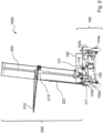
- the apparatus 1000 substantially comprises two portions 100 and 200 and, as a whole, appears as shown exemplified in Fig. 1 and Fig. 2 .
- the first portion 100 acts as a mobile base of the apparatus 1000 adapted to rest on a ground and advancing along a path
- the second portion 200 mechanically connected to the first portion 100, is dedicated to cutting and protrudes from the base of the apparatus 1000.
- the path on which the apparatus 1000 advances may be a predefined path, for example marked by detectors or sensors or guides placed in the vicinity of the hedge being cut, or it may be defined by the user by moving the apparatus 1000, as further explained below.
- the apparatus 1000 may rest on a portion of the ground that varies along the path taken due to the advancement thereof; when the apparatus 1000 rests on a portion of the ground, the apparatus 1000, in particular the first portion 100, defines a plane that may be inclined with respect to a horizontal plane, for example in the case where the portion of the ground on which it rests has unevenness and/or depressions.
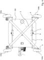
- the first portion 100 essentially comprises two pairs of wheels, 104a and 104b, for moving the apparatus 1000 and a plate 150, for example a substantially square shaped plate which, as will become clear later, serves as a support for the second portion 200 and further elements of the apparatus 1000.
- a plate 150 for example a substantially square shaped plate which, as will become clear later, serves as a support for the second portion 200 and further elements of the apparatus 1000.
- the first portion 100 may comprise a different number of wheels, but generally comprises at least two wheels. It has to be noted that an embodiment comprising three wheels (not shown in the figures) is also easily implemented according to the teachings of the present invention.
- the apparatus 1000 is motorised, i.e. the wheels are moved by a motor 155.
- the apparatus 1000 may be moved by means of mechanical tracks, also moved by a motor 155.
- the front wheels 104a and the rear wheels 104b are hinged to a support 4.
- This support 4 is in turn pivoted to the ends of two uprights 3.
- the two uprights 3 are positioned on the lower part of the plate 150 so as to form an "X" in which the ends of the uprights 3 are placed at the four corners of the plate 150.
- the wheels 104a and 104b work in pairs: both the front wheels 104a and the rear wheels 104b are steerable wheels and the wheels 104a are also traction wheels.
- the wheels 104a and 104b are designed to steer by means of a linkage capable of turning the wheels about the end of the upright 3.
- the supports 4 of the wheels 104a and the supports 4 of the wheels 104b are pivoted to a first end of a first lever 5.
- Said lever 5 is pivoted at one end to a second lever 6.
- the lever 6 transmitting the steering movement to a first wheel 104a and the lever 6 transmitting the steering movement to a second wheel 104a are rigidly connected to each other by means of a toothed bar 7.
- the lever 6 of a first wheel 104b and the lever 6 of a second wheel 104b are also rigidly connected to each other by means of a toothed bar 7; in particular, one end of the lever 6 of a first wheel 104b and one end of the lever 6 of a second wheel 104b are connected to the toothed bar 7 so that the toothed bar 7 can rigidly translate by transmitting movement to the respective levers 5 of the wheels 104a, 104b.
- the toothed bar 7 is designed to run on the toothing of a pinion 8 located in the lower part of the plate 150, i.e. the part of the plate facing the ground.
- the pinion 8 is rotated by a motor, in particular a servomotor, controlled by a user as explained later.
- the servomotor activates the rotation of the pinion 8
- the toothed bar 7 and the respective levers 6 rigidly translate in a horizontal direction in a first sense or in a second sense, causing the respective wheels to be steered in a first sense or in a second sense.
- the wheels 104a and the wheels 104b may be mutually independent steerable wheels, wherein each wheel 104a and 104b is mechanically connected to a servomotor that specifically controls the steering thereof.
- the first portion 100 further comprises a handlebar 160 adapted to be operated by a user.
- the handlebar 160 comprises a substantially horizontal guide bar pivoted to the first portion 100, in particular to the plate 150, by at least one, advantageously two, support rods.
- one or more joysticks including a lever adapted to be operated by a user to define the traction direction and/or the traction speed can be installed on the guide bar.
- one or more load cells 165 may be installed on the guide bar adapted to detect at least one force exerted on the handlebar 160, in particular at least one pressure exerted by a user on the guide bar, so that, based on the direction of the force exerted, for example forward or backward, i.e. a force having the sense of the horizontal component directed towards the front wheels 104a or towards the rear wheels 104b, the traction direction, in particular the traction sense, of the apparatus 1000 is defined.
- the traction speed of the apparatus 1000 is defined: a higher pressure corresponds to a higher speed and a lower pressure corresponds to a lower speed; obviously, a zero pressure corresponds to a zero speed.
- the advancement of the apparatus 1000 can be defined by a user by moving a joystick, for example a three-axis joystick placed on the handlebar 160.
- the displacement direction of the apparatus 1000 can be further defined.
- the apparatus 1000 may move along a direction parallel to the extension direction of the hedge being cut; in other words, the apparatus 1000 may be side by side with the hedge and move along a path parallel to the extension direction of the hedge.
- the extension direction of the hedge can be linear or it can have any non-linear direction, e.g. curved or with direction change angles along the extension of the hedge.
- the handlebar can be translated in a first direction, perpendicular to the extension direction of the hedge and in particular directed towards the hedge, or in a second direction, opposite to the first one, that is directed in the opposite sense to the extension direction of the hedge; basically, translating the handlebar in the first direction causes a movement towards the hedge, and translating the guide bar in the second direction causes a movement away from the hedge.
- the displacement direction of the apparatus 1000 may be defined by at least one, preferably two joysticks or load cells 165 placed on the handlebar guide bar 160, in particular by movement of the joystick lever by the user or by different pressure exerted by the user on the load cells 165.
- the handlebars 160 and its components are advantageously connected to a control unit 111 which receives electrical or electronic signals as input from them and sends command signals to the servo motor which rotates the pinions 8 of the steering system and to the traction motor connected to the traction wheels of the apparatus 1000.
- the first portion 100 further comprises sensors and measuring and/or control devices.
- the second portion 200 is mechanically connected to the first portion 100.
- the second portion 200 comprises a pillar 250 pivoted to the first portion 100 and capable of tilting on two axes A and B perpendicular to each other.
- the axis A is parallel to the extension direction of the hedge and the axis B is perpendicular to the extension direction of the hedge.
- the pillar 250 can be inclined or tilted (with respect to a zero reference position, typically coinciding with the vertical direction) using a movement system for each axis A and B.
- the movement system of the pillar 250 comprises a servomotor 115, a worm screw 116, a rod 117 and a slider having a threaded cavity.
- the pillar 250 has a square cross-section.
- the rod 117 consists of two levers that are parallel to each other.
- a first end of the levers of the rod 117 is constrained to the pillar 250, in particular a first lever is connected to a first side of the pillar 250 and a second lever is connected to a second side of the pillar 250 opposite the first one, so that the levers are parallel and spaced apart from each other by the thickness of the pillar 250.
- the slider is connected to the second end of the levers of the 117.
- the slider is positioned between the two levers, e.g. it is pivoted between the two levers.
- the slider has a threaded cavity into which the worm screw 116 is inserted.
- the worm screw 116 is adapted to rotate in a clockwise or anticlockwise direction, being moved by the servomotor 115.
- the worm screw 116 is adapted to transmit, by means of its rotation, a translational motion to the slider and consequently to the rod 117.
- a translation movement of the rod 117 corresponds to an inclination of the pillar 250.
- the threaded slider may act as a nut screw and rotate with respect to the worm screw 116 being placed by the servomotor 115 via a mechanical connection between the slider and the servomotor, for example by means of toothed pinions connected to the levers of the rod 117; during the rotational motion of the slider about the worm screw 116, the slider transmits a translational motion to the worm screw 116.
- the movement of the pillar 250 can be implemented with other different movement systems; for example, the rod 117 can be connected and moved by hydraulic pistons, or gear motors can be used, directly connected to the pillar 250pillar.
- a first movement system is adapted to tilt the pillar in direction A and a second movement system is adapted to tilt the pillar in direction or B.
- the servomotors 115 are controlled by a control unit 111 (see Fig. 3 ) operating by means of dedicated software which, as will be further explained below, is adapted to receive information from sensors of the apparatus 1000 and consequently adjust the position of one or more cutting blades of the apparatus 1000.
- At least one cutting blade is constrained to the pillar 250, in particular a first cutting blade 210, perpendicular to the direction of the axis of the pillar 250, and a second cutting blade 220 parallel to the direction of the axis of the pillar 250.
- a typical hedge trimmer blade is made up of blades with double serrated teeth sliding relative to each other.
- the first cutting blade 210 can comprise two or more modules that can slide telescopically relative to each other.
- the relative movement between the blades of the first cutting blade 210 and the second cutting blade 220 is operated by a belt drive system integral with at least two connecting rods connected to the first cutting blade 210 and the second cutting blade 220, respectively; alternatively, hydraulic pistons or electric motors may be used.
- the first cutting blade 210 is adapted to cut an upper profile of the hedge, while the second cutting blade 220 is adapted to cut a side profile of the hedge.
- the first cutting blade 210 is installed on a runner 215, the runner 215 being adapted to slide along a sliding guide, for example a rail, constrained to the pillar 250.
- the first cutting blade 210 is installed on the runner 215 by means of a quick coupling, for example by means of a bayonet coupling, so that it can be easily replaced and/or interchanged with different types of cutting blades.
- the sliding of the runner 215 is driven by a dedicated servomotor, which is also controlled by the control unit 111, so that the position of the runner 215 along the pillar 250 can vary, in particular according to the inclination of the ground with respect to a horizontal plane (and therefore of the first portion 100) and/or bumps and/or depressions on the ground.
- control unit 111 receives as input parameters and/or measurements and outputs an activating or deactivating command of the servomotor of the runner 215.
- control unit 111 receives as input the parameters set by the user via the human-machine interface 112.
- the control unit 111 may further receive measurements from inclinometers and/or gyroscopes or any other inclination detecting tool and/or accelerometers and/or barometers and/or motion sensors and/or advancement detectors (e.g. encoders) present on, for example, the first portion 100 or the second portion 200.
- motion sensors or advancement detectors may detect a direction and/or speed of travel of the apparatus 1000.
- the control unit 111 is adapted to receive information from the sensors repeatedly, in particular periodically: for example, the sensors present on the apparatus 1000 can collect data every 10 ms (milliseconds), i.e. substantially in real time, and the control unit 111 can adjust the inclination of the pillar 250 and/or the position of the first cutting blade 210 along the pillar with a time response comparable to that of data collection, i.e. substantially in real time.
- the data collection frequency and/or the control frequency can be set by the user.
- the user may have the option of defining a tolerance of the inclination of the pillar 250 with respect to the vertical direction, for example a tolerance of 1° with respect to the vertical direction.
- the user may have the possibility of defining a range of inclination with respect to the vertical direction in which the servomotor(s) controlling the movement system of the pillar 250 reduce their speed, so as to define a "slowing down zone" of the movement of the pillar 250 in proximity to the vertical direction.
- the wider the set range e.g. 0° - 8°
- the narrower the set range e.g. 0° - 2°
- the operation of the control unit 111 can also be linked to the advancement speed of the apparatus 1000.
- the control unit 111 can adjust the advancement speed of the apparatus 1000 depending on the frequency of data collection and/or the tolerances set by the user.
- the control unit 111 may decrease - possibly even cancel - the advancement speed of the apparatus until the desired adjustment has been made.
- control unit 111 is further connected to a human-machine interface 112, in particular a display and/or buttons and/or a joystick.
- the human-machine interface 112 is located, for example, on the handlebar 160 of the apparatus 1000 (see Fig. 1 and Fig. 7A ), so that the user can easily set cutting adjustment parameters of the apparatus 1000, for example the shape of the cut of the desired upper portion of the hedge, which, as explained below, can be, for example, parallel to the horizon line or inclined with respect to the horizon line or with parallel sections and perpendicular sections to the horizon line ("stepped" cutting).
- the inclinometers send to the control unit 111 data on the inclination of the plate 150 (and consequently of the ground) with respect to a horizontal plane and/or on the inclination of the first cutting blade 210 and/or on the inclination of the second cutting blade 220, in a first direction A and in a second direction B.
- an inclination of the second cutting blade 220 is equivalent to an inclination of the pillar 250 of the same magnitude, the second cutting blade 220 being constrained to the pillar 250, in particular in a direction parallel to the axis of the pillar 250.
- the control unit 111 when it receives as input values of inclination of the second cutting blade 220 other than zero in direction A and/or in direction B, i.e., when the pillar 250 is inclined with respect to a zero position, outputs a drive command to one or more servomotors 115 that adjust the inclination of the pillar 250 so that the inclination of the second cutting blade 220 returns to zero, i.e., that the pillar 250 returns to the zero position.
- an inclination of zero is equivalent to the condition in which the pillar 250 (and therefore the second cutting blade 220) is in the zero position.
- the control unit 111 then controls the servomotors 115 so that the zero position of the pillar 250 is maintained in the face of inclinations on the ground.
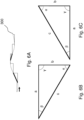
- the first cutting blade 210 for cutting the upper portion of the hedge is adjusted by the control unit 111 to the desired height, so as to follow, for example, an inclined line having an angle of inclination with respect to the horizon line, the amplitude of which is indicated as " ⁇ " (delta) in Fig. 5A and 5B is defined by the user.
- Fig. 5A and 5B the arrows indicate the directions of advancement of the apparatus 1000 on a ground profile 300.
- the user could set a cut of the upper portion of the hedge parallel to the horizon line.
- the ground profile 300 is represented in a simplified way with a regular line; however, it is unlikely to have such a ground profile but more realistically such a profile will be represented by a broken or curved line characterised by stretches of variable slope.
- control unit 111 outputs a command signal to the motor dedicated to the sliding of the runner 215 so as to adjust the height of the first cutting blade 210 along the pillar 250.
- control unit 111 in particular its software, regulates the drive of the motor dedicated to sliding the runner 215 on the basis of trigonometric operations.
- Fig. 6A in particular, two hypotenuses located respectively at a downhill and an uphill section of the ground profile 300 on which the apparatus 1000 advances have been highlighted.
- FIG. 6B an example of a right-angled triangle is provided, constructed by trigonometric operations on a downhill section of ground profile 300, in which the hypotenuse is denoted by the letter "c".
- FIG. 6C an example of a right-angled triangle is provided, constructed by trigonometric operations on an uphill section of ground profile 300, in which the hypotenuse is denoted by the letter "c".
- a cathetus "a" of the triangles in Fig. 6B and 6C represents the projection of the advancement range of the apparatus in a direction parallel to the horizon line
- the other cathetus "b” of the triangles is the variation of ground level (orthogonal to the horizon line and therefore orthogonal to the cathetus "a") in the detected advancement range
- the amplitude of the angle " ⁇ ", opposite the cathetus "b” is provided by the inclination of the ground 300 detected by the inclinometer placed on the plate 150.
- the control unit 111 by means of the software, detects the advancement range of the apparatus 1000 from the pulses sent by the encoder; the detected advancement constitutes the hypotenuse "c" of the imaginary triangle while the inclination detected by the inclinometer constitutes the amplitude of the angle " ⁇ ". The control unit 111 then processes the information received from the sensors and calculates the length of cathetus "b" opposite angle " ⁇ ".
- cathetus "b" calculated as above therefore constitutes the height variation of the ground in the measured advancement range.
- the value of the cathetus "b" also constitutes the height variation of the first cutting blade 210 necessary to compensate for the height variation of the ground in the measured advancement range with respect to the starting point of the cutting blade 210 or to the position of the first cutting blade 210 resulting from the previous measurement.
- control unit 111 will drive the motor that determines the sliding of the runner 215 to which the first cutting blade 210 is constrained in order to compensate for such height variation of the ground: the motor will move the runner 215 by an amount equal to the value of the cathetus "b".
- the value of the cathetus "b" can be a positive value (+) or a negative value (-), where the positive value corresponds to an increase in the height of the first cutting blade 210 above the ground and the negative value corresponds to a decrease in the height of the first cutting blade 210 above the ground.
- the angle " ⁇ ” is the angle formed by the intersection of the horizon line with the upper cutting line of the desired hedge 400 (see Fig. 5A and Fig. 5B ), where the amplitude of the angle " ⁇ " is set by the user on the human-machine interface 112. It has to be noted that in Figs. 5A and 5B the upper cutting line of the hedge 400 has been represented parallel to the simplified line representing the ground profile 300, i.e. in the represented case the amplitude of the angle " ⁇ " is equal to the amplitude of the angle " ⁇ ".
- the apparatus 1000 is able to compensate for depressions, bumps, disconnections and inclinations, which it encounters when advancing on an uneven ground profile (as schematically represented in Fig. 6A ).
- the apparatus 1000 shown in Fig. 1 and 2 and the apparatus 2000 shown as an example in Fig. 7A can be moved manually by a user, or pulled/pushed manually, in particular by gripping the handlebars 160 and 2160.
- the apparatus 2000 shown in Fig. 7A differs in particular from the apparatus 1000 shown in Fig. 1 and Fig. 2 due to the number of wheels used to move the apparatus: according to a person skilled in the art the further elements constituting the apparatus may be modified according to the teachings of the present invention. For example, with reference to Fig.
- the balance of the apparatus 2000 which comprises only a pair of wheels 2104a, is ensured by the user, who in particular, by gripping the handlebar 2160, acts as a third support point of the apparatus 2000.
- the wheels 2104a may be independent from each other: for example, in the case of steering the apparatus 2000, just one of the two wheels 2104a may be slowed down and/or braked in order to make a change of direction of the apparatus 2000, in particular to carry out a tight radius bend.
- this steering mode can be implemented in the case of three-wheel apparatus, where two wheels are steerable and a third wheel is free, i.e. its direction is not controlled.
- the steering of the apparatus 2000 may be carried out by applying a force to the handlebars 2160 to achieve a twist.
- the apparatus can be moved by an automatic guide system, e.g. it can run on a magnetic cable or magnetic track (typically underground), or on a physical guide, e.g. a steel cable, elevated above the ground, or on a track or monorail (see for example Fig. 7B ), or it can move freely on wheels using an automatic guide system (GPS, optical system, proximity sensors, laser).
- an automatic guide system GPS, optical system, proximity sensors, laser
- the wheels of the apparatus may be advantageously coupled or possibly replaced by pulleys or cylinders adapted to run along the track or monorail.
- the apparatus could comprise two or three wheels/pulleys/cylinders adapted to run along the rail or monorail and a wheel to run on a supporting rail or monorail; it has to be noted that the supporting rail or monorail could advantageously be replaced by a pre-existing structure in proximity to the hedge to be cut, for example a wall or fence.
- FIG. 7B an embodiment of the apparatus 3000 capable of sliding along a monorail 3105 associated with a wall 3106 is shown (note that in Fig. 7B only a portion of the wall is shown), e.g. an enclosing wall of a property in the immediate vicinity of the hedge to be cut.
- the apparatus 3000 may comprise a wheel (not visible in the figure) adapted to run along the monorail 3105 and at least one wheel 3104a (the example embodiment shown in Fig. 7B depicts three of them) adapted to run along the wall 3106.
- the wheel adapted to run along the monorail 3105 and the at least one wheel 3104a adapted to run along the wall 3106 are arranged in such a way as to ensure the balance of the apparatus 3000.
- the apparatus 3000 shown in Fig. 7B differs in particular from apparatus 1000 shown in Fig. 1 and Fig. 2 due to the movement system of the apparatus: according to a person skilled in the art the further elements constituting the apparatus may be modified according to the teachings of the present invention.
- the handlebar 160 may for example be a steering wheel and be twisted clockwise to steer in a first direction or anti-clockwise to steer in a second direction.
- the object disclosed herein relates to a method of adjusting the height of a cutting blade.
- the cutting blade is attached to a hedge trimmer that moves along a path over the ground on which the hedge to be cut is located and is height-adjustable in relation to the ground, in such a way as to vary its height with respect to the ground.
- the method comprises the steps of:
- control unit starts/shuts down the cutting blade drive motor or keeps the cutting blade drive motor started/shut down (step D) so that the height of the cutting blade in relation to the ground varies or not.
- step D the control unit starts or keeps the cutting blade drive motor running if the difference between the height variation of the ground calculated in two subsequent advancement ranges is greater than a predefined tolerance and switches the cutting blade drive motor off or keeps it off if the difference between the height variation of the ground calculated in two subsequent advancement ranges is zero or less than a predefined tolerance.
- control unit starts or keeps the engine running if the difference between the height variation of the ground calculated in two subsequent advancement ranges is greater than 1 cm in absolute value, while it stops or keeps the engine stopped if the difference between the height variation of the ground calculated in two subsequent advancement ranges is less than 1 cm in absolute value.
- the motor moves the cutting blade by an amount equal to the change in ground level, i.e. "b".
- the value of the cathetus "b” can be either a positive value (+) or a negative value (-), so that the translation movement of the cutting blade corresponds to an increase in height in relation to the ground if the value of "b” is positive, while it corresponds to a decrease in height in relation to the ground if the value of "b” is negative.
Landscapes
- Life Sciences & Earth Sciences (AREA)
- Biodiversity & Conservation Biology (AREA)
- Ecology (AREA)
- Forests & Forestry (AREA)
- Environmental Sciences (AREA)
- Harvester Elements (AREA)
- Fats And Perfumes (AREA)
Applications Claiming Priority (2)
| Application Number | Priority Date | Filing Date | Title |
|---|---|---|---|
| IT102021000003995A IT202100003995A1 (it) | 2021-02-22 | 2021-02-22 | Apparecchiatura tagliasiepi mobile |
| PCT/IB2022/051506 WO2022175905A1 (en) | 2021-02-22 | 2022-02-21 | Mobile hedge trimmer |
Publications (3)
| Publication Number | Publication Date |
|---|---|
| EP4294170A1 EP4294170A1 (en) | 2023-12-27 |
| EP4294170B1 true EP4294170B1 (en) | 2024-12-04 |
| EP4294170C0 EP4294170C0 (en) | 2024-12-04 |
Family
ID=75769852
Family Applications (1)
| Application Number | Title | Priority Date | Filing Date |
|---|---|---|---|
| EP22709040.4A Active EP4294170B1 (en) | 2021-02-22 | 2022-02-21 | Mobile hedge trimmer |
Country Status (8)
| Country | Link |
|---|---|
| US (1) | US20240122124A1 (pl) |
| EP (1) | EP4294170B1 (pl) |
| AU (1) | AU2022223528A1 (pl) |
| CA (1) | CA3205183A1 (pl) |
| ES (1) | ES2999012T3 (pl) |
| IT (1) | IT202100003995A1 (pl) |
| PL (1) | PL4294170T3 (pl) |
| WO (1) | WO2022175905A1 (pl) |
Families Citing this family (1)
| Publication number | Priority date | Publication date | Assignee | Title |
|---|---|---|---|---|
| CN117999976B (zh) * | 2023-11-15 | 2025-01-28 | 青岛理工大学 | 葡萄树自动修剪装置及自动修剪方法 |
Family Cites Families (8)
| Publication number | Priority date | Publication date | Assignee | Title |
|---|---|---|---|---|
| US4174604A (en) * | 1977-04-22 | 1979-11-20 | Wilson David J Jr | Hedge trimmer apparatus |
| DE2840854A1 (de) * | 1978-09-20 | 1980-04-03 | Werner Althen | Heckenscherenroller |
| US4577457A (en) * | 1982-02-12 | 1986-03-25 | Grant Spencer H | Tree trimming apparatus |
| JPS62214056A (ja) * | 1986-03-13 | 1987-09-19 | Aisin Seiki Co Ltd | 電気式パワ−ステアリング装置 |
| EP2206425A1 (fr) * | 2009-01-07 | 2010-07-14 | Cochet S.A. | Dispositif formant taille-haie équipant un engin motorisé, tel qu'une tondeuse autoportée |
| GB2475332B (en) * | 2009-11-17 | 2013-04-10 | Vivian Blick | Hedge cutter attachment |
| ITTV20120172A1 (it) * | 2012-09-07 | 2014-03-08 | Franco Garbin | Macchina tagliasiepe |
| CN105557335A (zh) * | 2015-12-15 | 2016-05-11 | 贾春燕 | 一种新型绿篱修剪车 |
-
2021
- 2021-02-22 IT IT102021000003995A patent/IT202100003995A1/it unknown
-
2022
- 2022-02-21 AU AU2022223528A patent/AU2022223528A1/en active Pending
- 2022-02-21 EP EP22709040.4A patent/EP4294170B1/en active Active
- 2022-02-21 PL PL22709040.4T patent/PL4294170T3/pl unknown
- 2022-02-21 CA CA3205183A patent/CA3205183A1/en active Pending
- 2022-02-21 US US18/277,068 patent/US20240122124A1/en active Pending
- 2022-02-21 ES ES22709040T patent/ES2999012T3/es active Active
- 2022-02-21 WO PCT/IB2022/051506 patent/WO2022175905A1/en not_active Ceased
Also Published As
| Publication number | Publication date |
|---|---|
| ES2999012T3 (en) | 2025-02-24 |
| EP4294170A1 (en) | 2023-12-27 |
| AU2022223528A1 (en) | 2023-09-07 |
| PL4294170T3 (pl) | 2025-03-03 |
| WO2022175905A1 (en) | 2022-08-25 |
| US20240122124A1 (en) | 2024-04-18 |
| CA3205183A1 (en) | 2022-08-25 |
| EP4294170C0 (en) | 2024-12-04 |
| IT202100003995A1 (it) | 2022-08-22 |
Similar Documents
| Publication | Publication Date | Title |
|---|---|---|
| US20140326471A1 (en) | Motor Grader Cross Slope Control With Articulation Compensation | |
| US5337846A (en) | Disaster relief robot and operation controller therefor | |
| US4722044A (en) | Boom control system | |
| US9624643B2 (en) | Blade tilt system and method for a work vehicle | |
| EP4294170B1 (en) | Mobile hedge trimmer | |
| US5005652A (en) | Method of producing a contoured work surface | |
| EP1740462B1 (en) | Self-propelling machine for wrapping stacked loads with protective film | |
| US6360518B1 (en) | Automatically adjusting shaker head harvester with steering correction and improved shaker head mounting | |
| US9782915B2 (en) | Track drive adjustment for a ground sawing machine | |
| EP0562148A1 (en) | Apparatus for guiding and steering earth boring casing | |
| CA2652056A1 (en) | Vector controlled leveling system for a forestry machine | |
| CN109863852B (zh) | 行驶作业机、插秧机、水田直播机、喷雾作业机 | |
| JP7229303B2 (ja) | 走行作業機 | |
| JP2017123804A (ja) | 作業車 | |
| JP6910269B2 (ja) | 走行作業機 | |
| US20050252190A1 (en) | Adjustable shaker head harvester with steering correction and improved shaker head mounting | |
| US20020129592A1 (en) | Automatically adjusting shaker head harvester with steering correction and improved shaker head mounting | |
| CN120188653A (zh) | 一种绿植修剪机 | |
| JPH08260419A (ja) | 土木用敷均し装置 | |
| EP0398073A2 (de) | Messeinrichtung | |
| USRE28979E (en) | Control system for road grader | |
| KR102190060B1 (ko) | 초기세팅 기능을 가지는 땅콩수확기 | |
| CN106392752A (zh) | 一种多功能管道切割工具及其使用方法 | |
| US10508409B2 (en) | Machine with a boom assembly and connection member | |
| CA2058212C (en) | Machining apparatus |
Legal Events
| Date | Code | Title | Description |
|---|---|---|---|
| STAA | Information on the status of an ep patent application or granted ep patent |
Free format text: STATUS: UNKNOWN |
|
| STAA | Information on the status of an ep patent application or granted ep patent |
Free format text: STATUS: THE INTERNATIONAL PUBLICATION HAS BEEN MADE |
|
| PUAI | Public reference made under article 153(3) epc to a published international application that has entered the european phase |
Free format text: ORIGINAL CODE: 0009012 |
|
| STAA | Information on the status of an ep patent application or granted ep patent |
Free format text: STATUS: REQUEST FOR EXAMINATION WAS MADE |
|
| 17P | Request for examination filed |
Effective date: 20230818 |
|
| AK | Designated contracting states |
Kind code of ref document: A1 Designated state(s): AL AT BE BG CH CY CZ DE DK EE ES FI FR GB GR HR HU IE IS IT LI LT LU LV MC MK MT NL NO PL PT RO RS SE SI SK SM TR |
|
| DAV | Request for validation of the european patent (deleted) | ||
| DAX | Request for extension of the european patent (deleted) | ||
| GRAP | Despatch of communication of intention to grant a patent |
Free format text: ORIGINAL CODE: EPIDOSNIGR1 |
|
| STAA | Information on the status of an ep patent application or granted ep patent |
Free format text: STATUS: GRANT OF PATENT IS INTENDED |
|
| INTG | Intention to grant announced |
Effective date: 20240709 |
|
| GRAS | Grant fee paid |
Free format text: ORIGINAL CODE: EPIDOSNIGR3 |
|
| GRAA | (expected) grant |
Free format text: ORIGINAL CODE: 0009210 |
|
| STAA | Information on the status of an ep patent application or granted ep patent |
Free format text: STATUS: THE PATENT HAS BEEN GRANTED |
|
| AK | Designated contracting states |
Kind code of ref document: B1 Designated state(s): AL AT BE BG CH CY CZ DE DK EE ES FI FR GB GR HR HU IE IS IT LI LT LU LV MC MK MT NL NO PL PT RO RS SE SI SK SM TR |
|
| REG | Reference to a national code |
Ref country code: CH Ref legal event code: EP |
|
| REG | Reference to a national code |
Ref country code: DE Ref legal event code: R096 Ref document number: 602022008425 Country of ref document: DE |
|
| REG | Reference to a national code |
Ref country code: IE Ref legal event code: FG4D |
|
| U01 | Request for unitary effect filed |
Effective date: 20241209 |
|
| U07 | Unitary effect registered |
Designated state(s): AT BE BG DE DK EE FI FR IT LT LU LV MT NL PT RO SE SI Effective date: 20241213 |
|
| REG | Reference to a national code |
Ref country code: ES Ref legal event code: FG2A Ref document number: 2999012 Country of ref document: ES Kind code of ref document: T3 Effective date: 20250224 |
|
| U20 | Renewal fee for the european patent with unitary effect paid |
Year of fee payment: 4 Effective date: 20250227 |
|
| PG25 | Lapsed in a contracting state [announced via postgrant information from national office to epo] |
Ref country code: HR Free format text: LAPSE BECAUSE OF FAILURE TO SUBMIT A TRANSLATION OF THE DESCRIPTION OR TO PAY THE FEE WITHIN THE PRESCRIBED TIME-LIMIT Effective date: 20241204 |
|
| PG25 | Lapsed in a contracting state [announced via postgrant information from national office to epo] |
Ref country code: NO Free format text: LAPSE BECAUSE OF FAILURE TO SUBMIT A TRANSLATION OF THE DESCRIPTION OR TO PAY THE FEE WITHIN THE PRESCRIBED TIME-LIMIT Effective date: 20250304 |
|
| PG25 | Lapsed in a contracting state [announced via postgrant information from national office to epo] |
Ref country code: GR Free format text: LAPSE BECAUSE OF FAILURE TO SUBMIT A TRANSLATION OF THE DESCRIPTION OR TO PAY THE FEE WITHIN THE PRESCRIBED TIME-LIMIT Effective date: 20250305 |
|
| PGFP | Annual fee paid to national office [announced via postgrant information from national office to epo] |
Ref country code: CH Payment date: 20250306 Year of fee payment: 4 |
|
| PGFP | Annual fee paid to national office [announced via postgrant information from national office to epo] |
Ref country code: PL Payment date: 20250220 Year of fee payment: 4 Ref country code: CZ Payment date: 20250205 Year of fee payment: 4 |
|
| PG25 | Lapsed in a contracting state [announced via postgrant information from national office to epo] |
Ref country code: RS Free format text: LAPSE BECAUSE OF FAILURE TO SUBMIT A TRANSLATION OF THE DESCRIPTION OR TO PAY THE FEE WITHIN THE PRESCRIBED TIME-LIMIT Effective date: 20250304 |
|
| PG25 | Lapsed in a contracting state [announced via postgrant information from national office to epo] |
Ref country code: SM Free format text: LAPSE BECAUSE OF FAILURE TO SUBMIT A TRANSLATION OF THE DESCRIPTION OR TO PAY THE FEE WITHIN THE PRESCRIBED TIME-LIMIT Effective date: 20241204 |
|
| PG25 | Lapsed in a contracting state [announced via postgrant information from national office to epo] |
Ref country code: IS Free format text: LAPSE BECAUSE OF FAILURE TO SUBMIT A TRANSLATION OF THE DESCRIPTION OR TO PAY THE FEE WITHIN THE PRESCRIBED TIME-LIMIT Effective date: 20250404 |
|
| U1N | Appointed representative for the unitary patent procedure changed after the registration of the unitary effect |
Representative=s name: BIRD & BIRD SOCIETA TRA AVVOCATI S.R.L.; IT |
|
| PG25 | Lapsed in a contracting state [announced via postgrant information from national office to epo] |
Ref country code: SK Free format text: LAPSE BECAUSE OF FAILURE TO SUBMIT A TRANSLATION OF THE DESCRIPTION OR TO PAY THE FEE WITHIN THE PRESCRIBED TIME-LIMIT Effective date: 20241204 |
|
| PG25 | Lapsed in a contracting state [announced via postgrant information from national office to epo] |
Ref country code: MC Free format text: LAPSE BECAUSE OF FAILURE TO SUBMIT A TRANSLATION OF THE DESCRIPTION OR TO PAY THE FEE WITHIN THE PRESCRIBED TIME-LIMIT Effective date: 20241204 |
|
| PLBE | No opposition filed within time limit |
Free format text: ORIGINAL CODE: 0009261 |
|
| STAA | Information on the status of an ep patent application or granted ep patent |
Free format text: STATUS: NO OPPOSITION FILED WITHIN TIME LIMIT |
|
| REG | Reference to a national code |
Ref country code: CH Ref legal event code: L10 Free format text: ST27 STATUS EVENT CODE: U-0-0-L10-L00 (AS PROVIDED BY THE NATIONAL OFFICE) Effective date: 20251015 |
|
| 26N | No opposition filed |
Effective date: 20250905 |
|
| REG | Reference to a national code |
Ref country code: CH Ref legal event code: U11 Free format text: ST27 STATUS EVENT CODE: U-0-0-U10-U11 (AS PROVIDED BY THE NATIONAL OFFICE) Effective date: 20260301 |
|
| U20 | Renewal fee for the european patent with unitary effect paid |
Year of fee payment: 5 Effective date: 20260227 |
|
| PGFP | Annual fee paid to national office [announced via postgrant information from national office to epo] |
Ref country code: GB Payment date: 20260227 Year of fee payment: 5 |
|
| PGFP | Annual fee paid to national office [announced via postgrant information from national office to epo] |
Ref country code: ES Payment date: 20260302 Year of fee payment: 5 |
|
| PGFP | Annual fee paid to national office [announced via postgrant information from national office to epo] |
Ref country code: IE Payment date: 20260227 Year of fee payment: 5 |