EP4294092A2 - Echtzeitbeurteilung von radiofrequenz (rf)-exposition - Google Patents
Echtzeitbeurteilung von radiofrequenz (rf)-exposition Download PDFInfo
- Publication number
- EP4294092A2 EP4294092A2 EP23207054.0A EP23207054A EP4294092A2 EP 4294092 A2 EP4294092 A2 EP 4294092A2 EP 23207054 A EP23207054 A EP 23207054A EP 4294092 A2 EP4294092 A2 EP 4294092A2
- Authority
- EP
- European Patent Office
- Prior art keywords
- maximum allowable
- time
- power level
- time slot
- distribution
- Prior art date
- Legal status (The legal status is an assumption and is not a legal conclusion. Google has not performed a legal analysis and makes no representation as to the accuracy of the status listed.)
- Granted
Links
Images







Classifications
-
- H—ELECTRICITY
- H04—ELECTRIC COMMUNICATION TECHNIQUE
- H04W—WIRELESS COMMUNICATION NETWORKS
- H04W52/00—Power management, e.g. Transmission Power Control [TPC] or power classes
- H04W52/04—Transmission power control [TPC]
- H04W52/18—TPC being performed according to specific parameters
- H04W52/22—TPC being performed according to specific parameters taking into account previous information or commands
- H04W52/225—Calculation of statistics, e.g. average or variance
-
- H—ELECTRICITY
- H04—ELECTRIC COMMUNICATION TECHNIQUE
- H04W—WIRELESS COMMUNICATION NETWORKS
- H04W52/00—Power management, e.g. Transmission Power Control [TPC] or power classes
- H04W52/04—Transmission power control [TPC]
- H04W52/30—Transmission power control [TPC] using constraints in the total amount of available transmission power
- H04W52/36—Transmission power control [TPC] using constraints in the total amount of available transmission power with a discrete range or set of values, e.g. step size, ramping or offsets
- H04W52/367—Power values between minimum and maximum limits, e.g. dynamic range
-
- H—ELECTRICITY
- H04—ELECTRIC COMMUNICATION TECHNIQUE
- H04W—WIRELESS COMMUNICATION NETWORKS
- H04W52/00—Power management, e.g. Transmission Power Control [TPC] or power classes
- H04W52/04—Transmission power control [TPC]
- H04W52/30—Transmission power control [TPC] using constraints in the total amount of available transmission power
- H04W52/36—Transmission power control [TPC] using constraints in the total amount of available transmission power with a discrete range or set of values, e.g. step size, ramping or offsets
-
- H—ELECTRICITY
- H04—ELECTRIC COMMUNICATION TECHNIQUE
- H04B—TRANSMISSION
- H04B1/00—Details of transmission systems, not covered by a single one of groups H04B3/00 - H04B13/00; Details of transmission systems not characterised by the medium used for transmission
- H04B1/38—Transceivers, i.e. devices in which transmitter and receiver form a structural unit and in which at least one part is used for functions of transmitting and receiving
- H04B1/3827—Portable transceivers
- H04B1/3833—Hand-held transceivers
- H04B1/3838—Arrangements for reducing RF exposure to the user, e.g. by changing the shape of the transceiver while in use
-
- H—ELECTRICITY
- H04—ELECTRIC COMMUNICATION TECHNIQUE
- H04W—WIRELESS COMMUNICATION NETWORKS
- H04W52/00—Power management, e.g. Transmission Power Control [TPC] or power classes
- H04W52/04—Transmission power control [TPC]
- H04W52/06—TPC algorithms
- H04W52/12—Outer and inner loops
-
- H—ELECTRICITY
- H04—ELECTRIC COMMUNICATION TECHNIQUE
- H04W—WIRELESS COMMUNICATION NETWORKS
- H04W52/00—Power management, e.g. Transmission Power Control [TPC] or power classes
- H04W52/04—Transmission power control [TPC]
- H04W52/38—TPC being performed in particular situations
-
- H—ELECTRICITY
- H04—ELECTRIC COMMUNICATION TECHNIQUE
- H04W—WIRELESS COMMUNICATION NETWORKS
- H04W88/00—Devices specially adapted for wireless communication networks, e.g. terminals, base stations or access point devices
- H04W88/02—Terminal devices
- H04W88/06—Terminal devices adapted for operation in multiple networks or having at least two operational modes, e.g. multi-mode terminals
Definitions
- aspects of the present disclosure relate generally to wireless devices, and more particularly, to assessing radio frequency (RF) exposure from a wireless device.
- RF radio frequency
- Modern wireless devices e.g., cellular phones
- RF radio frequency
- Modern wireless devices are generally required to limit a user's exposure to radio frequency (RF) radiation according to RF exposure limits set by domestic and international regulators.
- RF exposure limits set by domestic and international regulators.
- techniques have been developed to enable the wireless device to assess RF exposure from the wireless device in real time and adjust the transmission power of the wireless device accordingly to comply with the RF exposure limit.
- a first aspect relates to a wireless device.
- the wireless device includes a first transmitter configured to transmit first signals according to a first wireless communication technology, a second transmitter configured to transmit second signals according to a second wireless communication technology, and a processor coupled to the first and second transmitters.
- the processor is configured to determine a specific absorption rate (SAR) distribution for the first wireless communication technology, determine a power density (PD) distribution for the second wireless communication technology, combine the SAR distribution and the PD distribution to generate a combined RF exposure distribution, determine at least one first maximum allowable power level and at least one second maximum allowable power level for a future time slot based on the combined RF exposure distribution, set at least one transmission power limit for the first transmitter in the future time slot based on the at least one first maximum allowable power level, and set at least one transmission power limit for the second transmitter in the future time slot based on the at least one second maximum allowable power level.
- SAR specific absorption rate
- PD power density
- a second aspect relates to a method implemented in a wireless device.
- the method includes determining a specific absorption rate (SAR) distribution for a first wireless communication technology, determining a power density (PD) distribution for a second wireless communication technology, and combining the SAR distribution and the PD distribution to generate a combined RF exposure distribution.
- the method also includes determining at least one first maximum allowable power level and at least one second maximum allowable power level for a future time slot based on the combined RF exposure distribution, setting at least one transmission power limit for a first transmitter in the future time slot based on the at least one first maximum allowable power level, and setting at least one transmission power limit for a second transmitter in the future time slot based on the at least one second maximum allowable power level.
- a third aspect relates to a computer readable medium.
- the computer readable medium includes instructions stored thereon for determining a specific absorption rate (SAR) distribution for a first wireless communication technology, determining a power density (PD) distribution for a second wireless communication technology, and combining the SAR distribution and the PD distribution to generate a combined RF exposure distribution.
- SAR specific absorption rate
- PD power density
- the computer readable medium also includes instructions stored thereon for determining at least one first maximum allowable power level and at least one second maximum allowable power level for a future time slot based on the combined RF exposure distribution, setting at least one transmission power limit for a first transmitter in the future time slot based on the at least one first maximum allowable power level, and setting at least one transmission power limit for a second transmitter in the future time slot based on the at least one second maximum allowable power level.
- a fourth aspect relates to a wireless device.
- the wireless device includes a transmitter, and a processor coupled to the transmitter.
- the processor is configured to determine a specific absorption rate (SAR) distribution for a first wireless communication technology, determine a power density (PD) distribution for a second wireless communication technology, combine the SAR distribution and the PD distribution to generate a combined RF exposure distribution, and determine a maximum allowable time-average power level for a future time slot based on the combined RF exposure distribution, wherein the future time slot comprises multiple sub-time slots.
- SAR specific absorption rate
- PD power density
- the processor is also configured to determine a maximum allowable power level for each of the multiple sub-time slots based on the maximum allowable time-average power level for the future time slot, and set a transmission power limit for the transmitter in each of the sub-time slots based on the respective maximum allowable power level.
- a fifth aspect relates to a wireless device.
- the wireless device includes a transmitter, and a processor coupled to the transmitter.
- the processor is configured to determine a specific absorption rate (SAR) distribution for a first wireless communication technology, determine a power density (PD) distribution for a second wireless communication technology, combine the SAR distribution and the PD distribution to generate a combined RF exposure distribution, and determine a PD limit for a future time slot based on the combined RF exposure distribution, wherein the future time slot comprises multiple sub-time slots.
- the processor is also configured to determine a maximum allowable power level for each of the multiple sub-time slots based on the PD limit for the future time slot, and set a transmission power limit for the transmitter in each of the sub-time slots based on the respective maximum allowable power level.
- a seventh aspect relates to a wireless device.
- the wireless device includes a transmitter, and a processor coupled to the transmitter.
- the processor is configured to determine a maximum allowable time-average power level for a future time slot, determine a maximum allowable peak power level for the future time slot based on the determined maximum allowable time-average power level and a maximum allowable duty cycle, and set a peak power limit for the transmitter in the future time slot based on the maximum allowable peak power level.
- the one or more embodiments include the features hereinafter fully described and particularly pointed out in the claims.
- the following description and the annexed drawings set forth in detail certain illustrative aspects of the one or more embodiments. These aspects are indicative, however, of but a few of the various ways in which the principles of various embodiments may be employed and the described embodiments are intended to include all such aspects and their equivalents.
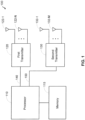
- FIG. 1 shows an example of a wireless device 100 in which aspects of the present disclosure described herein may be implemented.
- the wireless device 100 may comprise a mobile wireless device (e.g., a cellular phone), a laptop, a wireless access point, or some other wireless device.
- a mobile wireless device e.g., a cellular phone
- laptop e.g., a laptop
- wireless access point e.g., a wireless access point
- the wireless device 100 also includes a first transmitter 120, a first plurality of antennas 122-1 to 122-N coupled to the first transmitter 120, and a first bus 140 coupled between the first transmitter 120 and the processor 110.
- the first transmitter 120 is configured to transmit signals via one or more of the first plurality of antennas 122-1 to 122-N using one or more wireless communication technologies, including, but not limited to, a third generation (3G) technology (e.g., CDMA), a fourth generation (4G) technology (also known as Long Term Evolution (LTE)), a fifth generation (5G) technology, one or more technologies based on one or more IEEE 802.11 protocols (e.g., IEEE 802.1 1ac, IEEE 802.1 ln, IEEE 802.11ad, IEEE 802.1 1ax, IEEE 802.11ay, etc.), and/or one or more other technologies,
- the first transmitter 120 may be configured to transmit signals via multiple antennas 122-1 to 122-N using multiple-input-multiple-output (MIMO) transmission to MIMO
- the first transmitter 120 may be configured to transmit signals via multiple antennas 122-1 to 122-N using beamforming to direct transmissions toward another wireless device (not shown).
- the transmissions may be electrically steered by adjusting the relative phases and/or amplitudes of the transmit signals for the different antennas 122-1 to 122-N.
- the processor 110 may adjust transmission power for one or more of the antennas 122-1 to 122-N using an open power control loop and/or a closed power control loop.
- the wireless device 100 may receive a pilot signal from another wireless device (not shown) via a receiver (not shown).
- the processor 110 estimates channel conditions between the wireless device 100 and the other wireless device based on the received pilot signal, and adjusts the transmission power for one or more of the antennas 122-1 to 122-N based on the estimated channel conditions.
- the wireless device 100 receives a feedback signal from the other wireless device via a receiver (not shown), in which the feedback signal indicates channel conditions between the wireless device 100 and the other wireless device.
- the processor 110 adjusts the transmission power for one or more of the antennas 122-1 to 122-N based on the indicated channel conditions.
- the processor 110 may adjust transmission power for one or more of the antennas 122-1 to 122-N to keep RF exposure from the wireless device 100 within an RF exposure limit set by a regulator (e.g., FCC), as discussed further below.
- a regulator e.g., FCC
- the transmission power is constrained by the RF exposure limit.
- the wireless device 100 also includes a second transmitter 130, a second plurality of antennas 132-1 to 132-M coupled to the second transmitter 130, and a second bus 150 coupled between the second transmitter 130 and the processor 110.
- the second transmitter 130 is configured to transmit signals via one or more of the second plurality of antennas 132-1 to 132-M using one or more wireless communication technologies, including, but not limited to, a 3G technology, a 4G technology, a 5G technology, one or more technologies based on one or more IEEE 802.11 protocols (e.g., IEEE 802.11ac, IEEE 802.11n, IEEE 802.1 1ad, IEEE 802.11ax, IEEE 802.11ay, etc.), and/or one or more other technologies.
- the second transmitter 130 may transmit signals via multiple antennas 132-1 to 132-M using MIMO transmission, beamforming, and/or other method.
- the first transmitter 120 and the second transmitter 130 may simultaneously transmit signals using different wireless communication technologies, as discussed further below.
- the processor 110 interfaces with the second transmitter 130 via the second bus 150, which may include one or more signal lines between the processor 110 and the second transmitter 130.
- the processor 110 may process the data into one or more signals (e.g., baseband signals or intermediate-frequency signals).
- the processing performed by the processor 110 may include coding the data and modulating the coded data (e.g., using any one of a variety of different modulation schemes, including BPSK, QPSK, QAM, etc.).
- the processor 110 may output the one or more signals to the second transmitter 130 via the second bus 150.
- the second transmitter 130 may then process the one or more signals from the processor 110 into one or more RF signals for transmission via one or more of the antennas 132-1 to 132-M.
- the processing performed by the second transmitter 130 may include frequency up-conversion, power amplification, etc.
- the processor 110 may adjust the transmission power for one or more of the antennas 132-1 to 132-M.
- the second transmitter 130 may include multiple amplifiers (not shown) where each of the amplifiers is coupled to a respective one of the antennas 132-1 to 132-M.
- the processor 110 may output a respective control signal to the amplifier via the second bus 150 to control the gain of the amplifier.
- the processor 110 may adjust the transmission power for an antenna by adjusting the gain of the respective amplifier accordingly.
- the processor 110 may output one or more signals to the second transmitter 130 where each of the one or more signals corresponds to a respective one of the antennas 132-1 to 132-M.
- the processor 110 may adjust the transmission power for an antenna by adjusting the amplitude of the respective signal accordingly. It is to be appreciated that the present disclosure is not limited to the above examples, and that the processor 110 may employ other techniques to adjust transmission power.
- the processor 110 may adjust transmission power for one or more of the antennas 132-1 to 132-M using an open power control loop and/or a closed power control loop, as discussed above.
- the processor 110 may also adjust transmission power for one or more of the antennas 132-1 to 132-M to keep RF exposure from the wireless device 100 within an RF exposure limit set by a regulator, as discussed further below.
- aspects of the present disclosure enable the wireless device 100 to assess RF exposure in real time for cases where the wireless device 100 simultaneously transmits signals using multiple wireless communication technologies, as discussed further below.
- the wireless device 100 may simultaneously transmit signals using the first wireless communication technology (e.g., 3G, 4G, IEEE 802.11ac, etc.) in which RF exposure is measured in terms of SAR, and the second wireless communication technology (e.g., 5G, IEEE 802.11ad, etc.) in which RF exposure is measured in terms of PD.
- the first transmitter 120 may transmit first signals according to the first wireless communication technology
- the second transmitter 130 may transmit second signals according to the second wireless communication technology.
- the processor 110 may assess the combined RF exposure from the first and second technologies to ensure compliance with RF exposure limits, as discussed further below.
- the wireless device 100 may include multiple SAR distributions for the first technology stored in the memory 115.
- Each of the SAR distributions may correspond to a respective one of multiple transmit scenarios supported by the wireless device 100 for the first technology.
- the transmit scenarios may correspond to various combinations of antennas 122-1 to 122-N, frequency bands, channels and/or body positions, as discussed further below.
- SAR measurements may be performed for each one of the antennas 122-1 to 122-N to generate a SAR distribution for each one of the antennas 122-1 to 122-N.
- a SAR distribution for a transmit scenario in which two or more of the antennas 122-1 to 122-N are active may be generated by combining the SAR distributions for the two or more active antennas.
- the normalized SAR distribution for a transmit scenario may be generated by combining two or more normalized SAR distributions.
- a normalized SAR distribution for a transmit scenario in which two or more antennas are active may be generated by combining the normalized SAR distributions for the two or more active antennas.
- the normalized SAR distribution for each active antenna may be scaled by the respective transmission power level before combining the normalized SAR distributions for the active antennas.
- the combined SAR distribution may also be computed using equation (3a) in which i is an index for the active frequency bands, SAR norm_i is the normalized SAR distribution for the i th active frequency band, Tx i is the transmission power level for the i th active frequency band, and Tx SARi is the transmission power level for the normalized SAR distribution for the i th active frequency band.
- the wireless device 100 may include multiple PD distributions for the second technology stored in the memory 115.
- Each of the PD distributions may correspond to a respective one of multiple transmit scenarios supported by the wireless device 100 for the second technology.
- the transmit scenarios may correspond to various combinations of antennas 132-1 to 132-M, frequency bands, channels and/or body positions, as discussed further below.
- the PD distribution (also referred to as PD map) for each transmit scenario may be generated based on measurements (e.g., E-field measurements) performed in a test laboratory using a model of a human body. After the PD distributions are generated, the PD distributions are stored in the memory 115 to enable the processor 110 to assess RF exposure in real time, as discussed further below.
- Each PD distribution includes a set of PD values, where each PD value may correspond to a different location (e.g., on the model of the human body).
- the PD values in each PD distribution correspond to a particular transmission power level (e.g., the transmission power level at which the PD values were measured in the test laboratory). Since PD scales with transmission power level, the processor 110 may scale a PD distribution for any transmission power level by multiplying each PD value in the PD distribution by the following transmission power scaler: Tx c Tx PD where Tx c is a current transmission power level for the respective transmit scenario, and Tx PD is the transmission power level corresponding to the PD values in the PD distribution (e.g., the transmission power level at which the PD values were measured in the test laboratory).
- the wireless device 100 may support multiple transmit scenarios for the second technology.
- the transmit scenarios may be specified by a set of parameters.
- the set of parameters may include one or more of the following: an antenna parameter indicating one or more antennas used for transmission (i.e., active antennas), a frequency band parameter indicating one or more frequency bands used for transmission (i.e., active frequency bands), a channel parameter indicating one or more channels used for transmission (i.e., active channels), a body position parameter indicating the location of the wireless device 100 relative to the user's body location (head, trunk, away from the body, etc.), and/or other parameters.
- the normalized PD distribution for a transmit scenario may be generated by combining two or more normalized PD distributions.
- a normalized PD distribution for a transmit scenario in which two or more antennas are active may be generated by combining the normalized PD distributions for the two or more active antennas.
- the normalized PD distribution for each active antenna may be scaled by the respective transmission power level before combining the normalized PD distributions for the active antennas.
- the processor 110 may determine the first and second maximum allowable power levels as follows.
- the processor may determine a normalized SAR distribution for the first technology at a first transmission power level, determine a normalized PD distribution for the second technology at a second transmission power level, and combine the normalized SAR distribution and the normalized PD distribution to generate a combined normalized RF exposure distribution (referred to simply as a combined normalized distribution below).
- the value at each location in the combined normalized distribution may be determined by combining the normalized SAR value at the location with the normalized PD value at the location or another technique.
- the processor 110 limits (constrains) the transmission power level of the first transmitter 120 by the first maximum allowable power level. For example, if a power control loop is used for the first technology, the power control loop is allowed to set the transmission power level of the first transmitter 120 to a power level equal to or below the first maximum allowable power level, but not a power level exceeding the first maximum allowable power level.
- the processor 110 also limits (constrains) the transmission power level of the second transmitter 130 by the second maximum allowable power level.
- the transmission power levels for the first and second technologies may be initialized according to one or more power control loops, one or more desired data rates, one or more desired beam directions or sectors, etc.
- the transmission power levels may be initialized to a set of default transmission power levels.
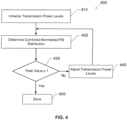
- the processor 110 compares the peak value in the combined normalized distribution with one. If the peak value in the combined normalized distribution is equal to or less than one (i.e., satisfies the condition ⁇ 1), then the processor 110 determines that the transmission power levels comply with RF exposure limits. In this case, the method 300 ends at block 350, and the processor 110 uses the transmission power levels as the maximum allowable power levels for the future time slot.
- the wireless device 100 may transmit signals using the second technology (e.g., 5G, IEEE 802.11ad, etc.) when the first technology is not active. In these cases, RF exposure from the first technology does not need to be considered to assess RF exposure compliance.
- the second technology e.g., 5G, IEEE 802.11ad, etc.
- the processor 110 may then determine maximum allowable power levels for the second technology that comply with the PD limit by performing the exemplary method illustrated in FIG. 4 .
- the processor 110 may determine RF exposure compliance for the case in which the first technology is active and the second technology is not active as follows.
- the processor 110 may compute a time-averaged normalized SAR distribution over a first time window (e.g., 6 minutes), and compare the peak value in the time-averaged normalized SAR distribution with one to assess RF exposure compliance. If the peak value is equal to or less than one (i.e., satisfies the condition ⁇ 1), then the processor 110 may determine RF exposure compliance.
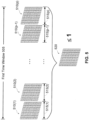
- FIG. 5 illustrates an example in which the processor 110 computes a time-averaged normalized SAR distribution over a first time window 505 (e.g., 6 minutes).
- the first time window 505 is divided into multiple time slots (i.e., time intervals). For instance, a 6-minute time window may be divided into 5-second time slots.
- each of the distributions 510(1)-510(p) is depicted as a two-dimensional distribution in FIG. 5 , it is to be appreciated that the present disclosure is not limited to this example.
- the processor 110 may determine a normalized SAR distribution for each time slot (e.g., according to equation (3a) or (3b)).
- the normalized SAR distribution for a time slot may be generated by combining two or more SAR distributions. For example, if two or more antennas are active during the time slot, then the processor 110 may combine the normalized SAR distributions for the two or more active antennas to generate the normalized SAR distribution for the time slot. For the case in which different transmission power levels are used for the active antennas, the processor 110 may scale the normalized SAR distribution for each active antenna by the transmission power level for the antenna.
- the processor 110 may determine maximum allowable power levels for a future time slot to ensure time-average RF exposure compliance.
- the time slots 515(1)-515(p-1) in FIG. 5 may correspond to previous transmissions by the wireless device 100, and the time slot 515(p) may correspond to the future time slot.
- the processor 110 may then determine transmission power levels for the future time slot 515(p) such that the peak value in the time-averaged normalized SAR distribution is equal to or less than one (i.e., satisfies the condition ⁇ 1 in equation (9b)).
- the processor 110 uses the transmission power levels that satisfy the condition for RF exposure compliance as the maximum allowable power levels for the future time slot 515(p), and sets the transmission power limits for the future time slot 515(p) according to the determined maximum allowable power levels.
- the processor 110 may determine the maximum allowable power levels for the future time slot 515(p) according to the exemplary method 600 illustrated in FIG. 6 .
- the processor 110 initializes the transmission power levels for the future time slot 515(p) according to the transmit scenario for the future time slot 515(p).
- the transmission power levels may be initialized according to a power control loop, a desired data rate, a desired beam direction or sector, etc. In one example, the transmission power levels may be initialized to a set of default transmission power levels.
- the processor 110 determines the time-averaged normalized SAR distribution based on the transmit scenario and transmission power levels at block 610 for the future time slot 515(p). Note that the transmission power levels for the previous time slots 515(1)-515(p-1) are known, as discussed above.
- the processor 110 compares the peak value in the time-averaged normalized SAR distribution with one to assess RF exposure compliance. If the peak value is equal to or less than one, then the method 600 ends at block 650. In this case, the processor 110 uses the transmission power levels initialized at block 610 as the maximum allowable power levels for the future time slot 515(p).
- the processor 110 adjusts the transmission power levels for the future time slot at block 640.
- the processor 110 may adjust the transmission power levels for the future time slot by reducing one or more of the transmission power levels for the future time slot.
- the processor 110 then repeats blocks 620 and 630 using the adjusted transmission power levels.
- the processor 110 may repeat blocks 640, 620 and 630 until the peak value in the time-averaged normalized SAR distribution is equal or less than one, at which point the transmission power levels comply with the SAR limit and the processor 110 uses the transmission power levels that comply with the SAR limit as the maximum allowable power levels for the future time slot 515 (p).
- the maximum allowable power levels may include a maximum allowable power level for each of the active antennas.
- the processor 110 limits (constrains) the transmission power level for each of the active antennas by the respective maximum allowable power level.
- the present disclosure is not limited to the exemplary method 600 illustrated in FIG. 6 , and that other methods may be employed to determine transmission power levels for the future time slot 515(p) such that the time-averaged normalized SAR distribution complies with the SAR limit.
- the processor 110 may determine maximum allowable power levels that result in the peak value of the time-averaged normalized SAR distribution being equal to or less than a value that is less than one for a conservative approximate analysis to determine the maximum allowable power levels with fewer computations.
- a regulator may require that a time-averaged PD distribution for the second technology not exceed a PD limit for the second technology. This allows the wireless device 100 to briefly exceed the PD limit as long as the time-averaged PD distribution does not exceed the PD limit.
- the processor 110 may determine RF exposure compliance for the case in which the second technology is active and the first technology is not active as follows.
- the processor 110 may compute a time-averaged normalized PD distribution over a second time window (e.g., 2 minutes), and compare the peak value in the time-averaged normalized PD distribution with one to assess RF exposure compliance. If the peak value is equal to or less than one (i.e., satisfies the condition ⁇ 1), then the processor 110 may determine RF exposure compliance.
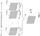
- FIG. 7 illustrates an example in which the processor 110 computes a time-averaged normalized PD distribution over a second time window 705 (e.g., 2 minutes).
- the second time window 705 is divided into multiple time slots (i.e., time intervals). For instance, a 2-minute time window may be divided into 5-second time slots.
- each of the distributions 710(1)-710(q) is depicted as a two-dimensional distribution in FIG. 7 , it is to be appreciated that the present disclosure is not limited to this example.
- the transmit scenario and/or transmission power levels for the second technology may vary over the second time window 705.
- the transmit scenario may be approximately constant over one time slot, but may vary from time slot to time slot within the second time window 705.
- the processor 110 may determine the normalized PD distribution for each time slot based on the transmit scenario and time-averaged transmission power levels during the time slot (e.g., according to equation (6a) or (tab)).
- the processor 110 may average the normalized PD distributions 710(1)-710(q) over the second time window 705 to generate a time-averaged normalized PD distribution 720.
- the processor 110 may determine maximum allowable power levels for a future time slot to ensure time-averaged RF exposure compliance.
- the time slots 715(1)-715(q-1) in FIG. 7 may correspond to previous transmissions by the wireless device 100, and the time slot 715(q) may correspond to a future transmission.
- the processor 110 may then determine transmission power levels for the future time slot 715(q) such that the peak value in the time-averaged normalized PD distribution is equal to or less than one (i.e., satisfies the condition ⁇ 1 in equation (10b)).
- the determined transmission power levels that comply with RF exposure levels are used as the maximum allowable power levels for the future time slot 715(q).
- the processor 110 sets the transmission power limits for the future time slot 715(q) according to the determined maximum allowable power levels.
- the processor 110 may determine the maximum allowable power levels for the future time slot 715(q) during time slot 715(q-1) so that the maximum allowable power levels for the future time slot 71 5(q) are ready at the start of the future time slot 715(q) for the processor 110 to enforce the maximum allowable power levels.
- the processor 110 may determine the maximum allowable power levels for the future time slot 715(q) according to the exemplary method 800 illustrated in FIG. 8 .
- the processor 110 initializes the transmission power levels for the future time slot 715(q) according to the transmit scenario for the future time slot 715(q).
- the transmission power levels may be initialized according to a power control loop, a desired data rate, a desired beam direction or sector, etc.
- the transmission power levels may be initialized to a set of default transmission power levels.
- the processor 110 determines the time-averaged normalized PD distribution based on the transmit scenario and transmission power levels at block 810 for the future time slot 715(q). Note that the transmission power levels for the previous time slots 715(1)-715(q-1) are known, as discussed above.
- the processor 110 compares the peak value in the time-averaged normalized PD distribution with one to assess RF exposure compliance. If the peak value is equal to or less than one, then the method 800 ends at block 850. In this case, the processor 110 uses the transmission power levels initialized at block 810 as the maximum allowable power levels for the future time slot 715(q).
- the processor 110 adjusts the transmission power levels 810 for the future time slot at block 840.
- the processor 1 10 may adjust the transmission power levels for the future time slot 715(q) by reducing one or more of the transmission power levels for the future time slot 715(q).
- the processor 110 then repeats blocks 820 and 830 using the adjusted transmission power levels.
- the processor 110 may repeat blocks 840, 820 and 830 until the peak value in the time-averaged PD distribution is equal or less than one, at which point the transmission power levels comply with the PD limit and the processor 110 uses the transmission power levels as the maximum allowable power levels for the future time slot 715(q).
- the maximum allowable power levels may include a maximum allowable power level for each of the active antennas.
- the processor 110 limits (constrains) the transmission power level for each of the active antennas by the respective maximum allowable power level.
- the present disclosure is not limited to the exemplary method 800 illustrated in FIG. 8 , and that other methods may be employed to determine transmission power levels for the future time slot 715(q) such that the time-averaged normalized PD distribution complies with the PD limit.
- the processor 110 may determine maximum allowable power levels for the future time slot 715(q) that result in the peak value in the time-averaged normalized PD distribution being approximately equal to or less than a value that is less than one.
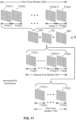
- the processor 110 may also determine time-averaged RF exposure compliance for the case where both the first technology and the second technology are active (i.e., the wireless device simultaneously transmits signals using the first and second technologies). To do this, the processor 110 may combine the time-averaged normalized SAR distribution 520 and the time-averaged normalized PD distribution 720 to generate a combined time-averaged normalized distribution 920, as illustrated in FIG. 9 . The processor 110 may then compare the peak value in the combined time-averaged normalized distribution 920 with one to assess time-averaged RF exposure compliance. If the peak value is equal to or less than one (i.e., satisfies the condition ⁇ 1), then the processor 110 may determine that the wireless device 100 is compliant.
- the first time window 505 for the time-averaged normalized SAR distribution and the second time window 705 for the time-averaged normalized PD distribution may be different in length.
- FIG. 9 shows an example in which the first time window 505 is longer than the second time window 705.
- the first time window 505 may be approximately 6 minutes in length and the second time window 705 may be approximately 2 minutes in length.
- the lengths of the first and second time windows may be specified by respective RF exposure regulations (e.g., established by the FCC or other regulatory body). Note that the lengths of the time windows 505 and 705 are not drawn to scale in FIG. 9 .
- the processor 110 may determine maximum allowable power levels for the future time slots 515(p) and 715(q) of the first and second technologies to ensure time-averaged RF exposure compliance.
- the future time slots 515(p) and 715(q) may be approximately aligned in time as shown in the example in FIG. 9 .
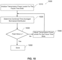
- the processor 110 may determine the maximum allowable power levels for the future time slots 515(p) and 715(q) according to the exemplary method 1000 illustrated in FIG. 10 .
- the maximum allowable power levels may include first maximum allowable power levels for the first technology and second maximum allowable power levels for the second technology.
- the processor 110 initializes the transmission power levels for the future time slots 515(p) and 715(q) according to the transmit scenarios for the future time slots 515(p) and 715(q). If the transmit scenario for the future time slot 515(p) for the first technology uses multiple active antennas, then the transmission power levels may include a transmission power level for each of the active antennas. Similarly, if the transmit scenario for the future time slot 715(q) for the second technology uses multiple active antennas, then the transmission power levels may include a transmission power level for each of the active antennas.
- the transmission power levels may be initialized according to one or more power control loops, one or more desired data rates, one or more desired beam directions or sectors, etc. In one example, the transmission power levels may be initialized to a set of default transmission power levels.
- the processor 110 determines the combined time-averaged normalized distribution 920 based on the transmission power levels for the future time slots 515(p) and 715(q). Note that the transmission power levels in the previous time slots 515(1)-515(p-1) for the first technology and the transmission power levels in the previous time slots 715(1)-715(q-1) for the second technology are known, as discussed above.
- the processor 110 compares the peak value in the combined time-averaged normalized distribution with one to assess RF exposure compliance. If the peak value is equal to or less than one, then the method 1000 ends at block 1050. In this case, the processor 110 uses the transmission power levels initialized at block 1010 as the maximum allowable power levels for the future time slots 515(p) and 715(q).
- the processor 110 adjusts the transmission power levels for the future time slots at block 1040.
- the processor 110 may adjust the transmission power levels for the future time slots by reducing one or more of the transmission power levels for the future time slots.
- the processor 110 then repeats blocks 1020 and 1030 using the adjusted transmission power levels.
- the processor 110 may repeat blocks 1040, 1020 and 1030 until the peak value in the combined time-averaged normalized distribution is equal or less than one, at which point the transmission power levels for the future time slots are compliant and the processor 110 uses the transmission power levels as the maximum allowable power levels.
- the determined maximum allowable power levels include the first maximum allowable power levels for the first technology and the second maximum allowable power levels for the second technology.
- the processor 110 sets the transmission power limits for the first transmitter 120 according to the first maximum allowable power levels and sets the transmission power limits for the second transmitter 130 according to the second maximum allowable power levels.
- the time-averaging window for PD is dependent on transmitting frequency (e.g., -2 minutes in 28GHz band and ⁇ 1 minute in 60GHz).
- frequency e.g., -2 minutes in 28GHz band and ⁇ 1 minute in 60GHz.
- the time-average PD distribution may be computed using a different time window for each frequency band.
- FIG. 11 shows an example in which two time-averaging windows are used for PD.
- the second time window 705 discussed above is used for the first frequency band (e.g., 28GHz band) and a third time window 1105 is used for the second frequency band (e.g., 60GHz band), in which the third time window 1105 is shorter than the second time window 705.
- the second time window 705 may have a length of approximately two minutes and the third time window 1105 may have a length of approximately one minute.
- the normalized PD distribution for each of the previous time slots 715(1) to 715(q-1) in the second time window 705 may be determined based on the transmit scenario and transmission power levels for the first frequency band during the time slot.
- the normalized PD distribution for the future time slot 715(q) is a function of transmission power levels for the first frequency band in the future time slot 715(q).
- the normalized PD distribution for each of the previous time slots 1115(1) to 1115(r-1) in the third time window 1105 may be determined based on the transmit scenario and transmission power levels for the second frequency band during the time slot.
- the normalized PD distribution for the future time slot 1115(r) is a function of transmission power levels for the second frequency band in the future time slot 1115(r).
- the time-average normalized PD distribution 720 may be computed according to equation (12) above, in which the time-average normalized PD distribution is a function of the transmission power levels for the first frequency band in the future time slot 715(q) and the transmission power levels for the second frequency band in the future time slot 1115(r).
- the time-averaged normalized PD distribution may be combined with the time-averaged normalized SAR distribution to obtain the combined time-averaged normalized distribution discussed above.
- the combined time-averaged normalized distribution is a function of the transmit scenario and transmission power levels for the first technology in the future time slot 515(p), the transmit scenario and transmission power levels for the first frequency band in the future time slot 715(q), and the transmit scenario and transmission power levels for the second frequency band in the future time slot 1115(r).
- the maximum allowable power levels may be determined by determining transmission power levels that result in the peak value of the combined time-averaged normalized distribution being equal to or less than one (e.g., according to the method 1000 illustrated in FIG. 10 ).
- the maximum allowable power levels include maximum allowable power levels for the first technology, maximum allowable power levels for the first frequency band, and maximum allowable power levels for the second frequency band.
- the processor 110 sets the transmission power limits for the first technology according to the maximum allowable power levels for the first technology, sets the transmission power limits for the first frequency band according to the maximum allowable power levels for the first frequency band, and sets the transmission power limits for the second frequency band according to the maximum allowable power levels for the second frequency band.
- time-averaging widows 705 and 1105 are used for PD in the above example, it is to be appreciated that more than two time-averaging widows may be used depending on the number of different frequency bands above 10GHz that are active. In general, the number of time-averaging windows used for PD may be equal to the number of active frequency bands above 10GHz, where each time-averaging window corresponds to a respective one of the active frequency bands.
- the wireless device 110 may simultaneously transmit signals at the first and second frequency bands (e.g., 28GHz and 60 GHz) while the first technology is not active.
- the processor 110 may determine maximum allowable power levels for the first and second frequency bands as follows.
- the processor may determine the time-average normalized PD distribution according to equation (12) in which the time-average normalized PD distribution is a function of the transmission power levels for the first frequency band in future time slot 715(q) and the transmission power levels for the second frequency band in future time slot 1115(r).
- the condition for RF exposure compliance is that the time-averaged normalized PD distribution 720 be equal to or less than one. Note that the time-average normalized PD distribution is not combined with the time-averaged normalized SAR distribution 520 in this case since the first technology is not active in this case.
- the processor 110 may determine maximum allowable power levels for the first and second technologies as follows.
- the processor 110 combines the time-averaged normalized SAR distribution 520 with the normalized PD distribution 710 for the future time slot 715(q) to obtain the combined normalized distribution 920 in which the combined normalized distribution 920 is a function of the transmission power levels for the first technology in future time slot 515(p) and the transmission power levels for the second technology in future time slot 715(q).
- the processor 110 may then determine transmission power levels for the first and second technologies that result in the peak value in the normalized distribution 920 being equal to or less than one, and use the determined transmission power levels as the maximum allowable power levels.
- the maximum allowable power levels include maximum allowable power levels for the first technology, and maximum allowable power levels for the second technology.
- the processor 110 sets the transmission power limits for the first transmitter 120 according to the maximum allowable power levels for the first technology and sets the transmission power limits for the second transmitter 130 band according to the maximum allowable power levels for the second technology.
- time slots 515(1)-515(p) discussed above may be equal in length or that two or more of the time slots 515(1)-515(p) may have different lengths.
- the future time slot 515(p) may also be referred to as a time interval and may have a length that is equal to or less than a tenth the length of the first time window 505. In one example, the future time slot 515(p) has a length of approximately 5 seconds and the first time window 505 has a length of approximately 6 minutes.
- time slots 715(1)-715(q) discussed above may be equal in length or that two or more of the time slots 715(1)-715(q) may have different lengths.
- the future time slot 715(q) may also be referred to as a time interval and may have a length that is equal to or less than a fifth the length of the second time window 705.
- the future time slot 715(q) has a length of approximately 5 seconds and the second time window 705 has a length of approximately 2 minutes.
- time slots 1115(1)-1115(r) discussed above may be equal in length or that two or more of the time slots 1115(1)-1115(r) may have different lengths.
- the future time slot 1115(r) may also be referred to as a time interval and may have a length that is equal to or less than a fifth the length of the third time window 1105.
- the future time slot 1115(r) has a length of approximately 5 seconds and the third time window 1105 has a length of approximately one minute.
- the first time window 505 may have a length that is at least 50 percent longer than the length of the second time window 705.
- the first time window 505 has a length of approximately 6 minutes
- the second time window 705 has a length of approximately 2 minutes, in which the lengths of the first and second time windows may be set by regulatory bodies.
- the lengths of the first and second time windows 505 and 705 set by the regulator bodies may change with time, and may vary between different regulatory bodies.
- regulatory bodies may define time windows that are dependent on transmitting frequency, for example, time-window length of 2 minutes for 28GHz band and time-window length of one minute for 60GHz bands. In that case, it is to be also appreciated that there could be one time window for SAR and two or more time windows for PD with each time window for PD corresponding to a given transmission frequency band.
- time slots 515(1)-515(p-1) in FIG. 5 are previous time slots, which are prior to future time slot 515(p).
- time windows 505, 705 and 1105 may be moving time-averaging windows.
- each time window is shifted by one time slot each time the maximum allowable power levels for a new future time slot are determined.
- time slot 515(p) is given as the future time slot.
- the processor 110 shifts the time window 505 by one time slot to cover time slots 515(2) to 515(p+1).
- the first communication technology discussed above may include multiple communication technologies in which SAR is used to assess RF exposure compliance.
- the first technology may include WWAN, WLAN, Bluetooth, etc.
- the first transmitter 120 may include multiple transmitters.
- SAR may have contributions from multiple sub-6GHz communication technologies (e.g., simultaneous transmissions of WWAN, WLAN and Bluetooth).
- the second communication technology discussed above may include multiple communication technologies in which PD is used to assess RF exposure compliance.
- the second technology may include mmWave/5G and mmWave/802.11ad.
- the second transmitter 130 may include multiple transmitters.
- PD may have contributions from multiple communication technologies (e.g., simultaneous transmissions of mmWave/5G and mmWave/802.11ad).
- a normalized distribution is compared with one to assess RF exposure compliance.
- a distribution e.g., SAR distribution, PD distribution, combined RF exposure distribution, etc.
- a limit value other than one may be used to define the condition for RF exposure compliance.
- the condition for RF compliance is that the normalized distribution be equal to or less than the limit value.
- the limit value may be set to a value less than one.
- the processor 110 may determine a maximum allowable power level for a transmitter (e.g., the first transmitter 120 or the second transmitter 130) for a future time slot (e.g., according to any of the methods described herein) and set a transmission power limit for the transmitter based on the determined maximum allowable power level.
- setting the transmission power limit based on the determined maximum allowable power level prevents a power level of the transmitter from exceeding the maximum allowable power level at any time during the future time slot.
- setting the transmission power limit based on the determined maximum allowable power level prevents a time-average of a power level of the transmitter over the future time slot from exceeding the maximum allowable power level.
- the power level may exceed the maximum allowable power level for a time interval shorter than the future time slot.
- the maximum allowable power level is a maximum allowable time-average power level over the future time slot.
- FIG. 14 illustrates an exemplary method 1400 implemented in a wireless device (e.g., wireless device 100) according to certain aspects of the present disclosure.
- a specific absorption rate (SAR) distribution for a first wireless communication technology is determined.
- the SAR distribution may comprise a time-averaged SAR distribution corresponding to a time-averaging window (e.g., time window 505).
- the first wireless communication technology may include one or more of the following: WWAN, WLAN, 3G, 4G, Bluetooth, etc.
- a power density (PD) distribution for a second wireless communication technology is determined.
- the PD distribution may comprise a time-averaged PD distribution corresponding to one or more time-averaging windows (e.g., time windows 705 and/or 1105).
- the second wireless communication technology may include one or more of the following: 5G, IEEE 802.11ad, etc.
- the SAR distribution and the PD distribution are combined to generate a combined RF exposure distribution.
- the combined RF exposure distribution may be a function of transmission power levels in the future time slot.
- the at least one first maximum allowable power level and the at least one second maximum allowable power levels may be determined by determining power levels for the transmission power levels that result in a peak value of the combined RF exposure distribution being equal to or less than a limit value (e.g., limit value of one) that ensures RF exposure compliance.
- At block 1450 at least one transmission power limit for a first transmitter in the future time slot is set based on the at least one first maximum allowable power level.
- Setting the at least transmission power limit for the first transmitter (e.g., first transmitter 120) based on the at least one first maximum allowable power level may limit transmission power levels of the first transmitter in the future time slot to the at least one first maximum allowable power level or limit a time-averaged transmission power level of the first transmitter over the future time slot to the at least one first maximum allowable power level.
- At block 1460 at least one transmission power limit for a second transmitter in the future time slot is set based on the at least one second maximum allowable power level.
- Setting the at least transmission power limit for the second transmitter (e.g., second transmitter 130) based on the at least one second maximum allowable power level may limit transmission power levels of the second transmitter in the future time slot to the at least one second maximum allowable power level or limit a time-averaged transmission power level of the second transmitter over the future time slot to the at least one second maximum allowable power level.
- block 1420 may be performed before block 1410 or both blocks 1410 and 1420 may be performed contemporaneously.
- block 1460 may be performed before block 1450 or both blocks 1450 and 1460 may be performed contemporaneously.
- the processor 110 determines a time-averaged SAR distribution 505 for the first technology over a first time window 505 and determines a time-averaged PD distribution 705 for the second technology over a second time window 705, in which the first time window 505 and the second time window 705 have different time durations (i.e., different lengths).
- the processor 110 then combines the time-averaged SAR distribution 505 and the time-averaged PD distribution 705 to obtain a combined time-averaged distribution 920, and determines a maximum allowable power level for the first technology and a maximum allowable power level for the second technology for a future time slot based on the combined time-averaged distribution 920.
- the processor 110 may make this determination every ⁇ t seconds, where ⁇ t seconds (e.g., 5 seconds) is the time duration of one time slot.
- ⁇ t seconds e.g., 5 seconds
- the processor 110 updates the maximum allowable power level for the first technology and the maximum allowable power level for the second technology every ⁇ t seconds (e.g., 5 seconds), and the first time window 505 and the second time window 705 are moving time-averaging windows, as discussed above.
- the same time-slot duration (e.g., 5 seconds) is used for the first technology and the second technology.
- PAR max 10 * log10 time_window/ ⁇ t
- time_window is the time duration of the respective time-averaging window (e.g., the first time window 505 for the first technology and the second time window 705 for the second technology)
- ⁇ t is the time duration of the future time slot.
- the average transmit power level for each technology in the future time slot is given by the respective maximum allowable power level determined for the future time slot.
- the maximum allowable PAR for the first technology equals 20dB.
- the second time window 705 for the second technology is 30 seconds and At is 5 seconds, then the maximum allowable PAR for the second technology equals 7.8dB.
- a high PAR may be required for the second technology (e.g., mmWave communication).
- the average transmit power may be approximately 8dBm and a transmit power of over 23dBm may be required to maintain a radio link at a cell edge, which translates into a PAR of over 15 dB.
- the maximum PAR for a technology may be increased by decreasing At (i.e., time duration of one time slot). Decreasing ⁇ t causes the processor 110 to update the maximum allowable power level for the first technology and the maximum allowable power level for the second technology more frequently, which consumes more computational resources for both technologies.
- decreasing ⁇ t in order to meet a PAR requirement for one technology may not be needed for another technology (e.g., the first technology) that already meets its PAR requirement. In this case, decreasing ⁇ t (i.e., time duration of one time slot) results in an unnecessary increase in computational resources for the other technology (e.g., first technology).
- aspects of the present disclosure allow the maximum allowable power levels for different technologies to be updated at different rates while still meeting total RF exposure compliance, as discussed further below.
- the maximum allowable power level for the second technology is updated in smaller time intervals than the first technology in order to increase the maximum allowable PAR for the second technology without requiring an increase in the computational load for the first technology.
- the future time slot 715(q) for the second technology is further divided (partitioned) into smaller time slots 1515(1) to 1515(N), as shown in FIG. 15 .
- the processor 110 may determine a normalized PD distribution 1520(1) to 1520(N) for each of the smaller time slots 1515(1) to 1515(N), as discussed further below.
- the smaller time slots 1515(1) to 1515(N) are referred to as sub-time slots for ease of discussion.
- the processor 110 determines the maximum allowable power level for the future time slot 715(q) in an outer loop.
- the processor 110 determines the maximum allowable power level for the future time slot 715(q) based on the combined time-averaged RF exposure distribution 920 as discussed above to ensure total RF exposure compliance.
- the processor 110 updates the maximum allowable power level for the future time slot 715(q) every ⁇ t seconds (i.e., duration of one time slot), as discussed above. For example, if the duration of one time slot is 5 seconds, then the processor 110 determines the maximum allowable power level for the future time slot 715(q) every 5 seconds. Note that the same time slot duration is used for the first technology and the second technology in the outer loop to meet total RF exposure compliance.
- the operations of the outer loop are discussed in greater detail above according to certain aspects with reference to FIG. 9 .
- the processor 110 may use the normalized PD distribution computed for the future time slot 715(q) in the outer loop as a normalized PD limit for the inner loop.
- the normalized PD distribution for the future time slot 715(q) is given by PD norm_q , which may be scaled by the maximum allowable power level determined for the future time slot 715(q).
- the PD limit for the inner loop may be given by the normalized PD distribution computed for the future time slot 715(q) in the outer loop, as discussed above.
- sub-time slots 1515(1) to 1515(1-n) are past sub-time slots relative to sub-time slot 1515(n) (i.e., prior in time to sub-time slot 1515(n)) and therefore correspond to previous transmissions by the second transmitter 130.
- Sub-time slot 1515(n) may be considered a future sub-time slot relative to sub-time slots 1515(1) to 1515(1-n). Since sub-time slots 1515(1) to 1515(n-1) correspond to previous transmissions, the processor 110 can determine the normalized PD distributions for sub-time slots 1515(1) to 1515(n-1) in equation (14) based on the previous transmission power levels for sub-time slots 1515(1) to 1515(n-1). For example, the processor 110 may record the transmission power levels for sub-time slots 1515(1) to 1515(n-1) and use the recorded transmission power levels to determine the normalized PD distributions for sub-time slots 1515(1) to 1515(n-1).
- the processor 110 may then determine a transmission power level for sub-time slot 1515(n) such that the expression on the left side of equation (14) is equal to or less than PD norm_lim (i.e., satisfies the condition ⁇ PD norm_lim ). For example, the processor 110 may determine the condition is met if the peak value in the expression on the left side is equal to or less than the peak value in PD norm_lim . The processor 110 may use then use the determined transmission power level for sub-time slot 1515(n) as a maximum allowable power level for sub-time slot 1515(n).
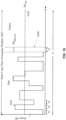
- FIG. 16 shows a point in time in which the maximum allowable power level is being determined for sub-time slot 1620 within the time-averaging window 1605.
- FIG. 16 shows the PDs (e.g., peak PD values) for the sub-time slots within the time averaging window 1605 preceding sub-time slot 1620 (referred to as past sub-time slots below).
- the past sub-time slots correspond to past transmissions with respect to the point in time shown in FIG. 16 .
- the PDs for sub-time slots succeeding sub-time slot 1620 within the time-averaging window 1605 are not shown in FIG. 16 since these sub-time slots correspond to future transmissions with respect to the point in time shown in FIG. 16 .
- the term (N-i) ⁇ PD R represents the portion of the PD allocation for the time-averaging window 1605 that is reserved for future sub-time slots (i.e., sub-time slots within the time-averaging window 1605 after the ith sub-time slot).
- the reserved PD R is multiplied by (N-i), which is the number of future sub-time slots after the ith sub-time slot.
- the portion of the PD allocation reserved for future sub-time slots is subtracted from the PD allocation for the time-averaging window 1605 since the portion of the PD allocation reserved for future sub-time slots is not available for the ith sub-time slot.
- PD reserve ratio is a reserve ratio.
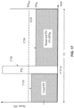
- the processor 110 when determining the allowed PD for the ith sub-time slot, the processor 110 takes into account the portion of the PD allocation for the time-averaging window 1605 that has already been used up by past sub-time slots. The processor 110 also reserves a portion of the remaining PD allocation for future sub-time slots.
- FIG. 17 shows a graphical representation of the portion of the PD allocation that has already been used up by past sub-time slots 1710, the allowed PD for the ith sub-time slot 1720, and the portion of the remaining PD allocation reserved for future sub-time slots 1730.
- the PD allocation for the time-averaging window 1605 is represented by the area under the PD limit line 1630.
- the processor 110 may determine an allowed PD for each of the sub-time slots within the time-averaging window 1605 for the inner loop (e.g., based on equation (15)). For the first sub-time slot, the portion of the PD allocation that has been used up is zero since there are no sub-time slots within the time-averaging window 1605 preceding the first sub-time slot. For the last sub-time slot, the portion of the PD allocation reserved for future sub-time slots is zero since there are no sub-time slots within the time-averaging window 1605 after the last sub-time slot. After determining the allowed PD for each sub-time slot, the processor 110 may determine a maximum allowable power level for the sub-time slot, and set a transmission power limit of the transmitter 130 for the sub-time slot based on the determined maximum allowable power level.
- the table 1810 includes an index for n different transmit scenarios for the transmitter 130.
- the n transmit scenarios may correspond to different beams, different user positions relative to the wireless device 100, etc.
- the table 1810 includes a corresponding transmission power level at a reference PD (labeled "Tx 1 " to "Tx n ").
- the transmission power levels for the different transmit scenarios at the reference PD may be predetermined by performing simulations and/or measurements on the wireless device 110, and prestored in the table 1810.
- the processor 110 may determine the transmit scenario for the sub-time slot and retrieve the transmission power level in the table 1810 corresponding to the determined transmit scenario. For example, if the transmit scenarios in table 1810 correspond to different beams, then the processor 110 may determine the beam for the sub-time slot, and retrieve the transmission power level in the table 1810 corresponding to the determined beam.
- the second inner loop is below the first inner loop.
- the second inner loop partitions each sub-time slot in the first inner loop into smaller sub-time slots.
- the second inner loop receives a PD limit from the first inner loop (e.g., allowed PD for the sub-time slot of the inner loop), and adjusts the maximum allowable power level within the sub-time slot such that the PD limit is met.
- the second inner loop determines the maximum allowable power level for each sub-time slot of the second inner loop within the sub-time slot of the first inner loop (e.g., based on equation (15) in which the PD limit is provided by the first inner loop). In this example, the maximum allowable power level is determined for each sub-time slot of the second inner loop.
- the processor 110 may use any of the techniques discussed above to determine maximum allowable power levels for different sub-6 GHz technologies at different rates. For example, the processor 110 may update the maximum allowable power level for LTE every 100 milliseconds, but update the maximum allowable power level for GSM every 5 seconds depending on how frequently or infrequently a technology changes. In this example, the processor 110 may determine a maximum allowable power level for LTE and a maximum allowable power level for GSM every 5 seconds in an outer loop. For LTE, the processor 110 may further divide a future time slot in the outer loop into sub-time slots (e.g., 50 sub-time slots), and determine a maximum allowable power level for each sub-time slot in an inner loop. The processor 110 may use the normalize SAR distribution for the future time slot in the outer loop as a normalized SAR limit in the inner loop for determining the maximum allowable power level for each sub-time slot in the inner loop.
- sub-time slots e.g., 50 sub-time slots
- setting the transmission power limit of a transmitter based on the determined maximum allowable time-average power level prevents a time-average of the transmission power level of the transmitter over the future time slot from exceeding the maximum allowable time-average power level.
- the instantaneous transmission power level of the transmitter is allowed to exceed the maximum allowable time-average power level during the future time slot as long as the time-average of the power level over the future time slot does not exceed the maximum allowable time-average power level.
- the maximum allowable time-average power level for a future time slot is used to set the maximum power limit of the corresponding transmitter so that the time-average of the transmission power level over the future time slot does not exceed the maximum allowable time-average power level.
- the maximum allowable power P max may be a limit on the maximum allowable instantaneous power level or peak power level of the corresponding transmitter.
- the maximum allowable power P max may be defined by a standard or a regulator body.
- the transmitter may transmit at a power level approximately equal to P max . during the future time slot at a duty cycle approximately equal to the maximum allowable duty cycle.
- the maximum duty cycle may have a value between 0 to 1.
- the processor 110 may determine a corresponding maximum allowable duty cycle for the future time slot based on equation (18). The processor 110 may then set a transmission duty cycle limit of the corresponding transmitter (e.g., transmitter 120 or 130) for the future time slot based on the determined the maximum allowable duty cycle. In this example, setting the transmission duty cycle limit based on the determined the maximum allowable duty cycle prevents the transmission duty cycle of the transmitter from exceeding the maximum allowable duty cycle for the future time slot. In other words, the transmission duty cycle of the transmitter for the future time slot is constrained by the determined maximum allowable duty cycle.
- the maximum allowable duty cycle can be provided by a radio frequency (RF) system (e.g., through uplink grant provided by the network), defined by standard, etc.
- RF radio frequency
- the processor 110 may convert the maximum allowable time-average power level for a future time slot into a maximum allowable duty cycle for the future time slot and set a transmission duty cycle limit of the corresponding transmitter based on the maximum allowable duty cycle.
- the processor 110 may also convert the maximum allowable time-average power level for a future time slot into a maximum allowable peak power for the future time slot and set a peak power limit of the corresponding transmitter based on the maximum allowable peak power.
- the maximum allowable time-average power level for the future time slot may be determined using any of the methods discussed above. For the example in which the future time slot is a future time slot in an outer loop, the maximum allowable time-average power level may correspond to the maximum allowable power level computed for the future time slot.
- a transmitter may transmit over a time window divided (discretized) into N time slots (not to be confused with the number of sub-time slots in FIG. 18 ).
- the processor 110 may also convert the maximum allowable time-average power level Max_avgP tk for the future time slot into a maximum allowable peak power for the future time slot (e.g., based on equation (19) using Max_avgP tk for Max_avg_P in equation (19)), and set a peak power limit of the corresponding transmitter based on the maximum allowable peak power.
- the memory 115 may include a computer readable medium including instructions stored thereon that, when executed by the processor 110, cause the processor 110 to perform the method 1400 and/or any other method described herein.
- the computer readable medium may include, by way of example, RAM (Random Access Memory), flash memory, ROM (Read Only Memory), PROM (Programmable Read-Only Memory), EPROM (Erasable Programmable Read-Only Memory), EEPROM (Electrically Erasable Programmable Read-Only Memory), registers, magnetic disks, optical disks, hard drives, or any other tangible non-transitory storage medium, or any combination thereof.
- a distribution may also be referred to as a map, a scan, or another term.
- an antenna may also be referred to as an antenna element or another term.
- a maximum allowable power level may also be referred to as a power level limit or another term.
- any reference to an element herein using a designation such as "first,” “second,” and so forth does not generally limit the quantity or order of those elements. Rather, these designations are used herein as a convenient way of distinguishing between two or more elements or instances of an element. Thus, a reference to first and second elements does not mean that only two elements can be employed, or that the first element must precede the second element.
- the word "exemplary” is used to mean “serving as an example, instance, or illustration.” Any implementation or aspect described herein as “exemplary” is not necessarily to be construed as preferred or advantageous over other aspects of the disclosure. Likewise, the term “aspects” does not require that all aspects of the disclosure include the discussed feature, advantage or mode of operation.
Landscapes
- Engineering & Computer Science (AREA)
- Computer Networks & Wireless Communication (AREA)
- Signal Processing (AREA)
- Physics & Mathematics (AREA)
- Probability & Statistics with Applications (AREA)
- Mobile Radio Communication Systems (AREA)
- Transmitters (AREA)
- Transceivers (AREA)
Priority Applications (1)
| Application Number | Priority Date | Filing Date | Title |
|---|---|---|---|
| EP25213593.4A EP4668906A3 (de) | 2018-07-05 | 2019-07-03 | Echtzeitbeurteilung von radiofrequenz (rf)-exposition |
Applications Claiming Priority (5)
| Application Number | Priority Date | Filing Date | Title |
|---|---|---|---|
| US201862694405P | 2018-07-05 | 2018-07-05 | |
| US201862696687P | 2018-07-11 | 2018-07-11 | |
| US16/460,894 US10652833B2 (en) | 2018-07-05 | 2019-07-02 | Evaluating radio frequency (RF) exposure in real time |
| PCT/US2019/040556 WO2020010232A1 (en) | 2018-07-05 | 2019-07-03 | Evaluating radio frequency (rf) exposure in real time |
| EP19745440.8A EP3818753B1 (de) | 2018-07-05 | 2019-07-03 | Evaluierung von hochfrequenz (rf)-exposition in echtzeit |
Related Parent Applications (1)
| Application Number | Title | Priority Date | Filing Date |
|---|---|---|---|
| EP19745440.8A Division EP3818753B1 (de) | 2018-07-05 | 2019-07-03 | Evaluierung von hochfrequenz (rf)-exposition in echtzeit |
Related Child Applications (2)
| Application Number | Title | Priority Date | Filing Date |
|---|---|---|---|
| EP25213593.4A Division EP4668906A3 (de) | 2018-07-05 | 2019-07-03 | Echtzeitbeurteilung von radiofrequenz (rf)-exposition |
| EP25213593.4A Division-Into EP4668906A3 (de) | 2018-07-05 | 2019-07-03 | Echtzeitbeurteilung von radiofrequenz (rf)-exposition |
Publications (3)
| Publication Number | Publication Date |
|---|---|
| EP4294092A2 true EP4294092A2 (de) | 2023-12-20 |
| EP4294092A3 EP4294092A3 (de) | 2024-03-13 |
| EP4294092B1 EP4294092B1 (de) | 2026-04-08 |
Family
ID=67441681
Family Applications (3)
| Application Number | Title | Priority Date | Filing Date |
|---|---|---|---|
| EP23207054.0A Active EP4294092B1 (de) | 2018-07-05 | 2019-07-03 | Echtzeitbeurteilung von radiofrequenz (rf)-exposition |
| EP19745440.8A Active EP3818753B1 (de) | 2018-07-05 | 2019-07-03 | Evaluierung von hochfrequenz (rf)-exposition in echtzeit |
| EP25213593.4A Pending EP4668906A3 (de) | 2018-07-05 | 2019-07-03 | Echtzeitbeurteilung von radiofrequenz (rf)-exposition |
Family Applications After (2)
| Application Number | Title | Priority Date | Filing Date |
|---|---|---|---|
| EP19745440.8A Active EP3818753B1 (de) | 2018-07-05 | 2019-07-03 | Evaluierung von hochfrequenz (rf)-exposition in echtzeit |
| EP25213593.4A Pending EP4668906A3 (de) | 2018-07-05 | 2019-07-03 | Echtzeitbeurteilung von radiofrequenz (rf)-exposition |
Country Status (5)
| Country | Link |
|---|---|
| US (5) | US10652833B2 (de) |
| EP (3) | EP4294092B1 (de) |
| JP (2) | JP7434192B2 (de) |
| CN (2) | CN112703785B (de) |
| WO (1) | WO2020010232A1 (de) |
Families Citing this family (55)
| Publication number | Priority date | Publication date | Assignee | Title |
|---|---|---|---|---|
| US10652833B2 (en) * | 2018-07-05 | 2020-05-12 | Qualcomm Incorporated | Evaluating radio frequency (RF) exposure in real time |
| DE102019124713B4 (de) * | 2018-11-27 | 2025-08-14 | Samsung Electronics Co., Ltd. | Vorrichtungen und Verfahren zur Steuerung einer Exposition gegenüber drahtloser Kommunikation |
| CN109495120B (zh) * | 2018-12-20 | 2020-10-16 | 深圳市万普拉斯科技有限公司 | 动态调整sar值方法、装置、移动终端和计算机存储介质 |
| US10841015B2 (en) | 2019-01-16 | 2020-11-17 | X Development Llc | Optical amplifier burst mode communication with variable duty cycle |
| WO2020199221A1 (zh) * | 2019-04-04 | 2020-10-08 | Oppo广东移动通信有限公司 | 一种资源配置方法、网络设备、终端设备 |
| US11924819B2 (en) * | 2019-05-24 | 2024-03-05 | Qualcomm Incorporated | Power limits based on signal type for managing maximum permissible exposure |
| JP2020205473A (ja) * | 2019-06-14 | 2020-12-24 | 株式会社村田製作所 | 通信回路及び通信回路の制御方法 |
| KR102650993B1 (ko) | 2019-08-14 | 2024-03-26 | 삼성전자주식회사 | Sar에 기반하여 송신 전력을 조정하는 전자 장치 및 그 동작 방법 |
| EP3796009B1 (de) * | 2019-09-18 | 2024-03-06 | Rohde & Schwarz GmbH & Co. KG | Sar-messung für eine kombinierte 5g- und lte-hf-vorrichtung |
| EP4038994A1 (de) * | 2019-10-01 | 2022-08-10 | IDAC Holdings, Inc. | Verringerung der spezifischen absorptionsrate und maximal zulässigen exposition |
| US20230141941A1 (en) * | 2020-04-01 | 2023-05-11 | Lenovo (Beijing) Ltd. | Method and apparatus for determining control resource set |
| US11664841B2 (en) * | 2020-07-15 | 2023-05-30 | Qualcomm Incorporated | Reductions in transmit power based on spatial distributions of radio frequency exposure in multi-transmitter scenarios |
| US12177797B2 (en) * | 2020-08-26 | 2024-12-24 | Qualcomm Incorporated | Time-averaged radio frequency (RF) exposure per antenna group |
| US11917559B2 (en) | 2020-08-26 | 2024-02-27 | Qualcomm Incorporated | Time-averaged radio frequency (RF) exposure per antenna group |
| US11716695B2 (en) | 2020-09-11 | 2023-08-01 | Qualcomm Incorporated | Exception-robust time-averaged radio frequency exposure compliance continuity |
| US11871359B2 (en) | 2020-09-11 | 2024-01-09 | Qualcomm Incorporated | Configurable radio frequency exposure compliance based on region |
| US12323961B2 (en) * | 2020-10-08 | 2025-06-03 | Qualcomm Incorporated | Allocation of transmit power in compliance with RF exposure requirements |
| US11917461B2 (en) | 2020-10-22 | 2024-02-27 | Qualcomm Incorporated | Techniques for measurement reporting and transmit power allocation in power-constrained environment |
| US12143938B2 (en) * | 2020-11-13 | 2024-11-12 | Qualcomm Incorporated | Radio frequency (RF) exposure compliance |
| US12096376B2 (en) | 2021-03-18 | 2024-09-17 | Qualcomm Incorporated | Techniques for uplink transmission-period-based transmission power for radio frequency exposure compliance |
| WO2022198215A1 (en) * | 2021-03-18 | 2022-09-22 | Qualcomm Incorporated | Techniques for uplink transmission-period-based transmission power for radio frequency exposure compliance |
| WO2022201971A1 (ja) * | 2021-03-22 | 2022-09-29 | ソニーグループ株式会社 | 通信制御装置、通信制御方法および通信装置 |
| US12289692B2 (en) | 2021-05-11 | 2025-04-29 | Mediatek Inc. | Method for improving transmission power management with compliance to regulations of radiofrequency exposure |
| US11432249B1 (en) * | 2021-06-16 | 2022-08-30 | Apple Inc. | Electronic devices with time domain radio-frequency exposure averaging |
| US12463675B2 (en) | 2021-08-05 | 2025-11-04 | Samsung Electronics Co., Ltd. | Radio frequency exposure estimation with radar for mobile devices |
| CN114466440B (zh) * | 2021-08-31 | 2025-05-02 | 华为技术有限公司 | 控制发射功率的方法及通信设备 |
| US12597978B2 (en) | 2021-10-20 | 2026-04-07 | Qualcomm Incorporated | Beam selection for higher uplink performance in view of exposure limits |
| US20230139016A1 (en) * | 2021-11-02 | 2023-05-04 | Qualcomm Incorporated | Time-averaged radio frequency (rf) exposure per exposure scenario |
| US12408124B2 (en) | 2021-11-02 | 2025-09-02 | Qualcomm Incorporated | Utilizing device state information in simultaneous radio transmission scenarios for radio frequency (RF) exposure compliance |
| KR20230068849A (ko) | 2021-11-11 | 2023-05-18 | 삼성전자주식회사 | 송출 전력 제어 방법 및 상기 방법을 수행하는 전자 장치 |
| WO2023086701A1 (en) * | 2021-11-12 | 2023-05-19 | Qualcomm Incorporated | Techniques for per communication link energy reservation |
| US12328682B2 (en) * | 2021-11-12 | 2025-06-10 | Qualcomm Incorporated | Techniques for per communication link energy reservation |
| US12471040B2 (en) | 2021-12-05 | 2025-11-11 | Qualcomm Incorporated | Energy allocation among multiple radios for radio frequency (RF) exposure compliance |
| WO2023102562A1 (en) * | 2021-12-05 | 2023-06-08 | Qualcomm Incorporated | Energy allocation among multiple radios and/or across different time windows for radio frequency (rf) exposure compliance |
| US20230180151A1 (en) * | 2021-12-05 | 2023-06-08 | Qualcomm Incorporated | Energy allocation among multiple radios and/or across different time windows for radio frequency (rf) exposure compliance |
| US20230189168A1 (en) * | 2021-12-13 | 2023-06-15 | Qualcomm Incorporated | Radio frequency exposure compliance for transitions between exposure control schemes |
| WO2023114749A1 (en) * | 2021-12-13 | 2023-06-22 | Qualcomm Incorporated | Radio frequency exposure compliance for transitions between exposure control schemes |
| US20230292255A1 (en) * | 2022-03-10 | 2023-09-14 | Samsung Electronics Co., Ltd. | Wireless electronic device with total exposure ratio (ter) control and operation method thereof |
| US12574063B2 (en) | 2022-06-01 | 2026-03-10 | Qualcomm Incorporated | Time-averaged radio frequency (RF) exposure across tissues and/or body locations |
| US20230397123A1 (en) * | 2022-06-01 | 2023-12-07 | Qualcomm Incorporated | Transmit energy allocation among different radios |
| CN119234449A (zh) * | 2022-06-01 | 2024-12-31 | 高通股份有限公司 | 不同无线电之间的发送能量分配 |
| US12574865B2 (en) | 2022-06-01 | 2026-03-10 | Qualcomm Incorporated | Multi-radio transmission adjustment for time-averaged radio frequency exposure |
| CN119234447A (zh) * | 2022-06-01 | 2024-12-31 | 高通股份有限公司 | 用于时间平均射频暴露的多无线电发送调整 |
| US20240015669A1 (en) * | 2022-07-08 | 2024-01-11 | Qualcomm Incorporated | Duty cycle determination for radio frequency exposure evaluation |
| US11923919B1 (en) | 2022-09-23 | 2024-03-05 | Qualcomm Incorporated | Efficient determination of RF exposure for MIMO transmitters |
| US12500620B2 (en) * | 2022-09-23 | 2025-12-16 | Qualcomm Incorporated | Radio frequency exposure compliance |
| US12418093B2 (en) * | 2022-11-04 | 2025-09-16 | Samsung Electronics Co., Ltd. | Electronic device and operating method of electronic device |
| WO2024111794A1 (ko) * | 2022-11-22 | 2024-05-30 | 삼성전자 주식회사 | 시간 평균 sar 모드를 수행하는 전자 장치 및 전자 장치의 동작 방법 |
| EP4387344A1 (de) | 2022-12-16 | 2024-06-19 | Nokia Solutions and Networks Oy | Bestimmung einer funksendeleistungsschwelle und zugehörige vorrichtungen, verfahren und computerprogramme |
| CN120380818A (zh) * | 2022-12-21 | 2025-07-25 | 高通股份有限公司 | 用于多个无线电的射频暴露管理 |
| US20240214953A1 (en) * | 2022-12-21 | 2024-06-27 | Qualcomm Incorporated | Radio frequency exposure management for multiple radios |
| US20240214952A1 (en) * | 2022-12-21 | 2024-06-27 | Qualcomm Incorporated | Radio frequency exposure management for authorized exceptions |
| US20250097858A1 (en) * | 2023-09-20 | 2025-03-20 | Qualcomm Incorporated | Radio frequency exposure limit compliance considering total energy specification |
| US20250097852A1 (en) * | 2023-09-20 | 2025-03-20 | Qualcomm Incorporated | Filter-based time-averaged radio frequency exposure evaluation |
| US20250386302A1 (en) * | 2024-06-14 | 2025-12-18 | Intel Corporation | Dynamic duty cycle time averaging specific absorption rate and power density human exposure mitigation |
Family Cites Families (40)
| Publication number | Priority date | Publication date | Assignee | Title |
|---|---|---|---|---|
| FR2832275B1 (fr) * | 2001-11-12 | 2004-11-19 | Evolium Sas | Procede d'ecretage de signaux a plusieurs porteuses transmis par un meme amplificateur non-lineaire |
| FR2832269B1 (fr) * | 2001-11-12 | 2004-11-19 | Evolium Sas | Procede d'optimisation du rendement d'un amplificateur destine a amplifier simultanement plusieurs porteuses modulees |
| US7031721B2 (en) * | 2002-05-16 | 2006-04-18 | Interdigital Technology Corporation | Method and system for avoiding power outages at the base station in cellular system using variable rate transmission |
| US7050405B2 (en) * | 2002-08-23 | 2006-05-23 | Qualcomm Incorporated | Method and system for a data transmission in a communication system |
| WO2006004968A2 (en) * | 2004-06-30 | 2006-01-12 | Neocific, Inc. | Methods and apparatus for power control in multi-carrier wireless systems |
| US7693119B2 (en) * | 2005-12-09 | 2010-04-06 | Hong Kong Applied Science And Technology Research Institute Co., Ltd. | Transmission power control over a wireless ad-hoc network |
| US8144634B2 (en) * | 2007-02-21 | 2012-03-27 | Telefonaktiebolaget Lm Ericsson (Publ) | Reducing automatic gain control process in time division duplex communication mode |
| DE102010011588B4 (de) * | 2010-03-12 | 2012-04-05 | Friedrich-Alexander-Universität Erlangen-Nürnberg | Verfahren zur Bestimmung von Sensitivitätsmatrizen für kritische Hotspots |
| US20120021707A1 (en) | 2010-07-26 | 2012-01-26 | Qualcomm Incorporated | Apparatus and method for adjustment of transmitter power in a system |
| EP2471191A1 (de) * | 2010-09-21 | 2012-07-04 | Broadcom Corporation | Übertragungsleistungsverwaltung für spezifische absorptionsraten |
| US8811918B2 (en) * | 2010-11-26 | 2014-08-19 | Broadcom Corporation | Distribution of transmit signal to multiple transmit antennas for reduction of measured specific absorption rate |
| TW201228104A (en) * | 2010-12-16 | 2012-07-01 | Quanta Comp Inc | Method to reduce specific absorption rate of electronic device and electronic device with low specific absorption rate |
| US8626101B2 (en) * | 2011-08-18 | 2014-01-07 | Apple Inc. | Wireless electronic device with antenna cycling |
| JP2013143575A (ja) * | 2012-01-06 | 2013-07-22 | Fujitsu Mobile Communications Ltd | 無線通信端末装置及び無線通信端末装置制御方法 |
| CN103067038B (zh) * | 2013-01-05 | 2017-08-18 | 中兴通讯股份有限公司 | 一种移动终端及降低比吸收率的方法 |
| US9225396B2 (en) | 2013-02-15 | 2015-12-29 | Intel Corporation | Apparatus, system and method of transmit power control for wireless communication |
| US9237531B2 (en) * | 2013-03-13 | 2016-01-12 | Qualcomm Incorporated | Real-time exposure assessment |
| US20140274189A1 (en) * | 2013-03-13 | 2014-09-18 | Motorola Mobility Llc | Reduced-power transmitting from a communications device |
| US9426754B2 (en) | 2013-06-13 | 2016-08-23 | Blackberry Limited | Device dynamic total RF power compensation |
| US10893488B2 (en) * | 2013-06-14 | 2021-01-12 | Microsoft Technology Licensing, Llc | Radio frequency (RF) power back-off optimization for specific absorption rate (SAR) compliance |
| US20150162942A1 (en) | 2013-12-06 | 2015-06-11 | Sony Corporation | Power control scheme for device to device networks |
| CN103702430A (zh) * | 2013-12-28 | 2014-04-02 | 杨学志 | 一种多级软时频复用和资源分配的方法、设备和系统 |
| WO2016069761A2 (en) * | 2014-10-28 | 2016-05-06 | New York University | System, method and computer-accessible medium for compliance assessment and active power management for safe use of radiowave emitting devices |
| US9380541B1 (en) * | 2015-06-02 | 2016-06-28 | Qualcomm Incorporated | Managing specific absorption rate distribution to maximize transmit power of a wireless device |
| KR102640447B1 (ko) | 2015-06-16 | 2024-02-26 | 한국전자통신연구원 | 기지국 전자파 노출 관리 장치 및 방법 |
| US9961647B2 (en) * | 2015-06-16 | 2018-05-01 | Electronics And Telecommunications Research Institute | Device and method for controlling exposure of electromagnetic waves from base station |
| US9622187B2 (en) * | 2015-08-26 | 2017-04-11 | Qualcomm Incorporated | Real-time specific absorption rate implementation in wireless devices |
| US20170322247A1 (en) * | 2016-05-05 | 2017-11-09 | Qualcomm Incorporated | Device and method for rf exposure assessment at millimeter wave frequencies |
| KR102661725B1 (ko) * | 2016-09-09 | 2024-04-30 | 삼성전자주식회사 | 전력을 제어하기 위한 장치 및 방법 |
| KR102577176B1 (ko) * | 2016-10-21 | 2023-09-12 | 삼성전자주식회사 | 송신 전력을 제어하기 위한 전자장치 및 방법 |
| TWI604372B (zh) * | 2016-11-14 | 2017-11-01 | 瑞昱半導體股份有限公司 | 用於記憶卡存取之中介電路 |
| US10129834B2 (en) * | 2017-03-31 | 2018-11-13 | Intel Corporation | Transmission power control methods and devices |
| US10224974B2 (en) * | 2017-03-31 | 2019-03-05 | Microsoft Technology Licensing, Llc | Proximity-independent SAR mitigation |
| GB2567146B (en) | 2017-09-28 | 2022-04-13 | Red Flint Llp | Method and system for secure storage of digital data |
| KR102465059B1 (ko) * | 2017-10-19 | 2022-11-09 | 삼성전자주식회사 | 전력을 제어하기 위한 방법 및 그 전자 장치 |
| WO2019200613A1 (zh) * | 2018-04-20 | 2019-10-24 | 华为技术有限公司 | 一种降低电磁辐射比吸收率的方法及设备 |
| US10652833B2 (en) * | 2018-07-05 | 2020-05-12 | Qualcomm Incorporated | Evaluating radio frequency (RF) exposure in real time |
| US11924819B2 (en) * | 2019-05-24 | 2024-03-05 | Qualcomm Incorporated | Power limits based on signal type for managing maximum permissible exposure |
| US12302258B2 (en) * | 2021-03-09 | 2025-05-13 | Qualcomm Incorporated | Techniques for power control for dual subscribers |
| US20240114469A1 (en) * | 2022-09-23 | 2024-04-04 | Qualcomm Incorporated | Radio frequency exposure evaluation per surface |
-
2019
- 2019-07-02 US US16/460,894 patent/US10652833B2/en active Active
- 2019-07-03 WO PCT/US2019/040556 patent/WO2020010232A1/en not_active Ceased
- 2019-07-03 EP EP23207054.0A patent/EP4294092B1/de active Active
- 2019-07-03 CN CN201980057688.8A patent/CN112703785B/zh active Active
- 2019-07-03 JP JP2020572730A patent/JP7434192B2/ja active Active
- 2019-07-03 EP EP19745440.8A patent/EP3818753B1/de active Active
- 2019-07-03 CN CN202411558853.7A patent/CN119172843A/zh active Pending
- 2019-07-03 EP EP25213593.4A patent/EP4668906A3/de active Pending
-
2021
- 2021-01-04 US US17/141,150 patent/US11457416B2/en active Active
-
2022
- 2022-09-21 US US17/949,976 patent/US11792740B2/en active Active
-
2023
- 2023-10-16 US US18/487,557 patent/US12213080B2/en active Active
-
2024
- 2024-02-07 JP JP2024017387A patent/JP7663733B2/ja active Active
- 2024-12-20 US US18/990,867 patent/US20250261127A1/en active Pending
Also Published As
| Publication number | Publication date |
|---|---|
| US20240172126A1 (en) | 2024-05-23 |
| US11792740B2 (en) | 2023-10-17 |
| EP4294092A3 (de) | 2024-03-13 |
| EP4668906A3 (de) | 2026-03-04 |
| JP2024063011A (ja) | 2024-05-10 |
| EP3818753B1 (de) | 2023-11-15 |
| EP3818753C0 (de) | 2023-11-15 |
| US11457416B2 (en) | 2022-09-27 |
| US10652833B2 (en) | 2020-05-12 |
| KR20210025065A (ko) | 2021-03-08 |
| US20230012908A1 (en) | 2023-01-19 |
| US12213080B2 (en) | 2025-01-28 |
| CN119172843A (zh) | 2024-12-20 |
| CN112703785B (zh) | 2024-11-22 |
| JP7434192B2 (ja) | 2024-02-20 |
| JP2021529469A (ja) | 2021-10-28 |
| US20250261127A1 (en) | 2025-08-14 |
| JP7663733B2 (ja) | 2025-04-16 |
| US20220286974A9 (en) | 2022-09-08 |
| US20210127337A1 (en) | 2021-04-29 |
| EP3818753A1 (de) | 2021-05-12 |
| CN112703785A (zh) | 2021-04-23 |
| EP4668906A2 (de) | 2025-12-24 |
| US20200015171A1 (en) | 2020-01-09 |
| WO2020010232A1 (en) | 2020-01-09 |
| EP4294092B1 (de) | 2026-04-08 |
Similar Documents
| Publication | Publication Date | Title |
|---|---|---|
| US12213080B2 (en) | Evaluating radio frequency (RF) exposure in real time | |
| US11664841B2 (en) | Reductions in transmit power based on spatial distributions of radio frequency exposure in multi-transmitter scenarios | |
| US20260106638A1 (en) | Radio frequency exposure compliance | |
| US11923919B1 (en) | Efficient determination of RF exposure for MIMO transmitters | |
| US20230292255A1 (en) | Wireless electronic device with total exposure ratio (ter) control and operation method thereof | |
| KR102959529B1 (ko) | 실시간 라디오 주파수(rf) 노출 평가 |
Legal Events
| Date | Code | Title | Description |
|---|---|---|---|
| PUAI | Public reference made under article 153(3) epc to a published international application that has entered the european phase |
Free format text: ORIGINAL CODE: 0009012 |
|
| STAA | Information on the status of an ep patent application or granted ep patent |
Free format text: STATUS: REQUEST FOR EXAMINATION WAS MADE |
|
| 17P | Request for examination filed |
Effective date: 20231031 |
|
| AC | Divisional application: reference to earlier application |
Ref document number: 3818753 Country of ref document: EP Kind code of ref document: P |
|
| AK | Designated contracting states |
Kind code of ref document: A2 Designated state(s): AL AT BE BG CH CY CZ DE DK EE ES FI FR GB GR HR HU IE IS IT LI LT LU LV MC MK MT NL NO PL PT RO RS SE SI SK SM TR |
|
| REG | Reference to a national code |
Ref country code: DE Free format text: PREVIOUS MAIN CLASS: H04W0052380000 Ref country code: DE Ref legal event code: R079 Ref document number: 602019083581 Country of ref document: DE Free format text: PREVIOUS MAIN CLASS: H04W0052380000 Ipc: H04W0052360000 |
|
| PUAL | Search report despatched |
Free format text: ORIGINAL CODE: 0009013 |
|
| AK | Designated contracting states |
Kind code of ref document: A3 Designated state(s): AL AT BE BG CH CY CZ DE DK EE ES FI FR GB GR HR HU IE IS IT LI LT LU LV MC MK MT NL NO PL PT RO RS SE SI SK SM TR |
|
| RIC1 | Information provided on ipc code assigned before grant |
Ipc: H04W 52/38 20090101ALI20240208BHEP Ipc: H04W 52/36 20090101AFI20240208BHEP |
|
| GRAP | Despatch of communication of intention to grant a patent |
Free format text: ORIGINAL CODE: EPIDOSNIGR1 |
|
| STAA | Information on the status of an ep patent application or granted ep patent |
Free format text: STATUS: GRANT OF PATENT IS INTENDED |
|
| INTG | Intention to grant announced |
Effective date: 20250708 |
|
| GRAJ | Information related to disapproval of communication of intention to grant by the applicant or resumption of examination proceedings by the epo deleted |
Free format text: ORIGINAL CODE: EPIDOSDIGR1 |
|
| STAA | Information on the status of an ep patent application or granted ep patent |
Free format text: STATUS: REQUEST FOR EXAMINATION WAS MADE |
|
| INTC | Intention to grant announced (deleted) | ||
| GRAP | Despatch of communication of intention to grant a patent |
Free format text: ORIGINAL CODE: EPIDOSNIGR1 |
|
| STAA | Information on the status of an ep patent application or granted ep patent |
Free format text: STATUS: GRANT OF PATENT IS INTENDED |
|
| INTG | Intention to grant announced |
Effective date: 20251204 |
|
| GRAS | Grant fee paid |
Free format text: ORIGINAL CODE: EPIDOSNIGR3 |
|
| GRAA | (expected) grant |
Free format text: ORIGINAL CODE: 0009210 |
|
| STAA | Information on the status of an ep patent application or granted ep patent |
Free format text: STATUS: THE PATENT HAS BEEN GRANTED |
|
| AC | Divisional application: reference to earlier application |
Ref document number: 3818753 Country of ref document: EP Kind code of ref document: P |
|
| AK | Designated contracting states |
Kind code of ref document: B1 Designated state(s): AL AT BE BG CH CY CZ DE DK EE ES FI FR GB GR HR HU IE IS IT LI LT LU LV MC MK MT NL NO PL PT RO RS SE SI SK SM TR |
|
| REG | Reference to a national code |
Ref country code: CH Ref legal event code: F10 Free format text: ST27 STATUS EVENT CODE: U-0-0-F10-F00 (AS PROVIDED BY THE NATIONAL OFFICE) Effective date: 20260408 Ref country code: GB Ref legal event code: FG4D |
|
| REG | Reference to a national code |
Ref country code: DE Ref legal event code: R096 Ref document number: 602019083581 Country of ref document: DE |