EP4293822B1 - Mehrfrequenz- und mehrstrahlige unabhängige elektrisch verstellbare antenne - Google Patents
Mehrfrequenz- und mehrstrahlige unabhängige elektrisch verstellbare antenne Download PDFInfo
- Publication number
- EP4293822B1 EP4293822B1 EP23173157.1A EP23173157A EP4293822B1 EP 4293822 B1 EP4293822 B1 EP 4293822B1 EP 23173157 A EP23173157 A EP 23173157A EP 4293822 B1 EP4293822 B1 EP 4293822B1
- Authority
- EP
- European Patent Office
- Prior art keywords
- component
- phase shifter
- electromagnetic lens
- push component
- oscillator units
- Prior art date
- Legal status (The legal status is an assumption and is not a legal conclusion. Google has not performed a legal analysis and makes no representation as to the accuracy of the status listed.)
- Active
Links
Images



Classifications
-
- H—ELECTRICITY
- H01—ELECTRIC ELEMENTS
- H01Q—ANTENNAS, i.e. RADIO AERIALS
- H01Q1/00—Details of, or arrangements associated with, antennas
- H01Q1/12—Supports; Mounting means
- H01Q1/22—Supports; Mounting means by structural association with other equipment or articles
- H01Q1/24—Supports; Mounting means by structural association with other equipment or articles with receiving set
- H01Q1/241—Supports; Mounting means by structural association with other equipment or articles with receiving set used in mobile communications, e.g. GSM
- H01Q1/246—Supports; Mounting means by structural association with other equipment or articles with receiving set used in mobile communications, e.g. GSM specially adapted for base stations
-
- H—ELECTRICITY
- H01—ELECTRIC ELEMENTS
- H01Q—ANTENNAS, i.e. RADIO AERIALS
- H01Q5/00—Arrangements for simultaneous operation of antennas on two or more different wavebands, e.g. dual-band or multi-band arrangements
- H01Q5/40—Imbricated or interleaved structures; Combined or electromagnetically coupled arrangements, e.g. comprising two or more non-connected fed radiating elements
- H01Q5/45—Imbricated or interleaved structures; Combined or electromagnetically coupled arrangements, e.g. comprising two or more non-connected fed radiating elements using two or more feeds in association with a common reflecting, diffracting or refracting device
-
- H—ELECTRICITY
- H01—ELECTRIC ELEMENTS
- H01Q—ANTENNAS, i.e. RADIO AERIALS
- H01Q1/00—Details of, or arrangements associated with, antennas
- H01Q1/12—Supports; Mounting means
-
- H—ELECTRICITY
- H01—ELECTRIC ELEMENTS
- H01Q—ANTENNAS, i.e. RADIO AERIALS
- H01Q1/00—Details of, or arrangements associated with, antennas
- H01Q1/36—Structural form of radiating elements, e.g. cone, spiral, umbrella; Particular materials used therewith
-
- H—ELECTRICITY
- H01—ELECTRIC ELEMENTS
- H01Q—ANTENNAS, i.e. RADIO AERIALS
- H01Q15/00—Devices for reflection, refraction, diffraction or polarisation of waves radiated from an antenna, e.g. quasi-optical devices
- H01Q15/02—Refracting or diffracting devices, e.g. lens, prism
-
- H—ELECTRICITY
- H01—ELECTRIC ELEMENTS
- H01Q—ANTENNAS, i.e. RADIO AERIALS
- H01Q15/00—Devices for reflection, refraction, diffraction or polarisation of waves radiated from an antenna, e.g. quasi-optical devices
- H01Q15/02—Refracting or diffracting devices, e.g. lens, prism
- H01Q15/08—Refracting or diffracting devices, e.g. lens, prism formed of solid dielectric material
-
- H—ELECTRICITY
- H01—ELECTRIC ELEMENTS
- H01Q—ANTENNAS, i.e. RADIO AERIALS
- H01Q15/00—Devices for reflection, refraction, diffraction or polarisation of waves radiated from an antenna, e.g. quasi-optical devices
- H01Q15/14—Reflecting surfaces; Equivalent structures
- H01Q15/18—Reflecting surfaces; Equivalent structures comprising plurality of mutually inclined plane surfaces, e.g. corner reflector
-
- H—ELECTRICITY
- H01—ELECTRIC ELEMENTS
- H01Q—ANTENNAS, i.e. RADIO AERIALS
- H01Q15/00—Devices for reflection, refraction, diffraction or polarisation of waves radiated from an antenna, e.g. quasi-optical devices
- H01Q15/23—Combinations of reflecting surfaces with refracting or diffracting devices
-
- H—ELECTRICITY
- H01—ELECTRIC ELEMENTS
- H01Q—ANTENNAS, i.e. RADIO AERIALS
- H01Q19/00—Combinations of primary active antenna elements and units with secondary devices, e.g. with quasi-optical devices, for giving the antenna a desired directional characteristic
- H01Q19/06—Combinations of primary active antenna elements and units with secondary devices, e.g. with quasi-optical devices, for giving the antenna a desired directional characteristic using refracting or diffracting devices, e.g. lens
-
- H—ELECTRICITY
- H01—ELECTRIC ELEMENTS
- H01Q—ANTENNAS, i.e. RADIO AERIALS
- H01Q19/00—Combinations of primary active antenna elements and units with secondary devices, e.g. with quasi-optical devices, for giving the antenna a desired directional characteristic
- H01Q19/06—Combinations of primary active antenna elements and units with secondary devices, e.g. with quasi-optical devices, for giving the antenna a desired directional characteristic using refracting or diffracting devices, e.g. lens
- H01Q19/062—Combinations of primary active antenna elements and units with secondary devices, e.g. with quasi-optical devices, for giving the antenna a desired directional characteristic using refracting or diffracting devices, e.g. lens for focusing
-
- H—ELECTRICITY
- H01—ELECTRIC ELEMENTS
- H01Q—ANTENNAS, i.e. RADIO AERIALS
- H01Q19/00—Combinations of primary active antenna elements and units with secondary devices, e.g. with quasi-optical devices, for giving the antenna a desired directional characteristic
- H01Q19/10—Combinations of primary active antenna elements and units with secondary devices, e.g. with quasi-optical devices, for giving the antenna a desired directional characteristic using reflecting surfaces
- H01Q19/106—Combinations of primary active antenna elements and units with secondary devices, e.g. with quasi-optical devices, for giving the antenna a desired directional characteristic using reflecting surfaces using two or more intersecting plane surfaces, e.g. corner reflector antennas
-
- H—ELECTRICITY
- H01—ELECTRIC ELEMENTS
- H01Q—ANTENNAS, i.e. RADIO AERIALS
- H01Q21/00—Antenna arrays or systems
- H01Q21/24—Combinations of antenna units polarised in different directions for transmitting or receiving circularly and elliptically polarised waves or waves linearly polarised in any direction
- H01Q21/26—Turnstile or like antennas comprising arrangements of three or more elongated elements disposed radially and symmetrically in a horizontal plane about a common centre
-
- H—ELECTRICITY
- H01—ELECTRIC ELEMENTS
- H01Q—ANTENNAS, i.e. RADIO AERIALS
- H01Q21/00—Antenna arrays or systems
- H01Q21/28—Combinations of substantially independent non-interacting antenna units or systems
-
- H—ELECTRICITY
- H01—ELECTRIC ELEMENTS
- H01Q—ANTENNAS, i.e. RADIO AERIALS
- H01Q21/00—Antenna arrays or systems
- H01Q21/30—Combinations of separate antenna units operating in different wavebands and connected to a common feeder system
-
- H—ELECTRICITY
- H01—ELECTRIC ELEMENTS
- H01Q—ANTENNAS, i.e. RADIO AERIALS
- H01Q3/00—Arrangements for changing or varying the orientation or the shape of the directional pattern of the waves radiated from an antenna or antenna system
- H01Q3/26—Arrangements for changing or varying the orientation or the shape of the directional pattern of the waves radiated from an antenna or antenna system varying the relative phase or relative amplitude of energisation between two or more active radiating elements; varying the distribution of energy across a radiating aperture
- H01Q3/30—Arrangements for changing or varying the orientation or the shape of the directional pattern of the waves radiated from an antenna or antenna system varying the relative phase or relative amplitude of energisation between two or more active radiating elements; varying the distribution of energy across a radiating aperture varying the relative phase between the radiating elements of an array
- H01Q3/32—Arrangements for changing or varying the orientation or the shape of the directional pattern of the waves radiated from an antenna or antenna system varying the relative phase or relative amplitude of energisation between two or more active radiating elements; varying the distribution of energy across a radiating aperture varying the relative phase between the radiating elements of an array by mechanical means
-
- H—ELECTRICITY
- H01—ELECTRIC ELEMENTS
- H01Q—ANTENNAS, i.e. RADIO AERIALS
- H01Q5/00—Arrangements for simultaneous operation of antennas on two or more different wavebands, e.g. dual-band or multi-band arrangements
- H01Q5/40—Imbricated or interleaved structures; Combined or electromagnetically coupled arrangements, e.g. comprising two or more non-connected fed radiating elements
- H01Q5/42—Imbricated or interleaved structures; Combined or electromagnetically coupled arrangements, e.g. comprising two or more non-connected fed radiating elements using two or more imbricated arrays
-
- Y—GENERAL TAGGING OF NEW TECHNOLOGICAL DEVELOPMENTS; GENERAL TAGGING OF CROSS-SECTIONAL TECHNOLOGIES SPANNING OVER SEVERAL SECTIONS OF THE IPC; TECHNICAL SUBJECTS COVERED BY FORMER USPC CROSS-REFERENCE ART COLLECTIONS [XRACs] AND DIGESTS
- Y02—TECHNOLOGIES OR APPLICATIONS FOR MITIGATION OR ADAPTATION AGAINST CLIMATE CHANGE
- Y02D—CLIMATE CHANGE MITIGATION TECHNOLOGIES IN INFORMATION AND COMMUNICATION TECHNOLOGIES [ICT], I.E. INFORMATION AND COMMUNICATION TECHNOLOGIES AIMING AT THE REDUCTION OF THEIR OWN ENERGY USE
- Y02D30/00—Reducing energy consumption in communication networks
- Y02D30/70—Reducing energy consumption in communication networks in wireless communication networks
Definitions
- the present invention relates to the technical field of mobile communications, and in particular to a multi-frequency and multi-beam independent electrically adjustable antenna.
- MIMO Multiple Input Multiple Output
- T4R Transmit 4 Receive
- 2T2R 2 Transmit 2 Receive
- the technical solution like the one described in Chinese Patent Application No. 2020106750469 , entitled “Dual Vertically Polarized Multi-beam Antenna with Artificial Dielectric Cylinder", cannot adjust a beam down tilt angle of an antenna, which is extremely inconvenient to use.
- a beam direction is adjusted by moving an oscillator or electromagnetic lens, which causes the position of the oscillator to be shifted relative to the electromagnetic lens, and a signal of the oscillator to change in direction after passing through the electromagnetic lens.
- the oscillator or electromagnetic lens must be moved as a whole, and an outer shell for mounting the antenna must have enough space for movement.
- the size of antenna is large, which is not conducive to installation and carrying.
- US2021/399433A1 discloses lensed base station antennas having functional structures that provide a step approximation of a luneberg lens.
- CN111900553B discloses a dual-vertical polarization artificial dielectric cylinderical multi-beam antenna.
- US2021/288405A1 discloses mechanical transmission mechanism and base station antenna.
- CN112886276A discloses multi-beam lens antenna and active lens antenna system.
- the present invention aims to provide a multi-frequency and multi-beam independent electrically adjustable antenna.
- the multi-frequency and multi-beam independent electrically adjustable antenna has advantages of simple structure, scientific design, small size, flexible setting of beam direction, and being able to meet the requirements of an MIMO technology for the number of channels.
- a technical solution of the present invention is realized as follows.
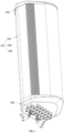
- a multi-frequency and multi-beam independent electrically adjustable antenna is provided, which may include: a first electromagnetic lens, a second electromagnetic lens, a mounting plate, a reflecting plate, oscillator units A1 to A32, oscillator units B1 to B8, and phase shifters C1 to C12.
- the reflecting plate is bent to form a first reflecting surface, a second reflecting surface, a third reflecting surface and a fourth reflecting surface; the first reflecting surface, the second reflecting surface, the third reflecting surface and the fourth reflecting surface are successively connected to form a wrap angle.
- the first electromagnetic lens and the second electromagnetic lens are both cylindrical lenses, the first electromagnetic lens and the second electromagnetic lens are both partially positioned in the wrap angle, and a central axis of the first electromagnetic lens is collinear with a central axis of the second electromagnetic lens.
- the first electromagnetic lens, the second electromagnetic lens, the reflecting plate and the mounting plate are fixed relative to each other, and the mounting plate is on a side of the reflecting plate facing away from the first electromagnetic lens and the second electromagnetic lens.
- the oscillator units A17 to A24 are all mounted on the third reflecting surface, the oscillator units A17 to A24 are arranged in sequence along a straight line L3, each of the oscillator units A17 to A20 is set to have a signal receiving and transmitting direction towards the first electromagnetic lens and perpendicular to the central axis of the first electromagnetic lens, and each of the oscillator units A21 to A24 is set to have a signal receiving and transmitting direction towards the second electromagnetic lens and perpendicular to the central axis of the second electromagnetic lens.
- the oscillator units A25 to A32 are all mounted on the fourth reflecting surface, the oscillator units A25 to A32 are arranged in sequence along a straight line L4, each of the oscillator units A25 to A28 is set to have a signal receiving and transmitting direction towards the first electromagnetic lens and perpendicular to the central axis of the first electromagnetic lens, and each of the oscillator units A29 to A32 is set to have a signal receiving and transmitting direction towards the second electromagnetic lens and perpendicular to the central axis of the second electromagnetic lens.
- the oscillator units B1 to B4 are all mounted on the reflecting plate, the oscillator units B1 to B4 are arranged in sequence along a side L5 formed by connecting the first reflecting surface and the second reflecting surface, and each of the oscillator units B1 and B2 is set to have a signal receiving and transmitting direction towards the first electromagnetic lens and perpendicular to the central axis of the first electromagnetic lens, and each of the oscillator units B3 and B4 is set to have a signal receiving and transmitting direction towards the second electromagnetic lens and perpendicular to the central axis of the second electromagnetic lens.
- the oscillator units B5 to B8 are all mounted on the reflecting plate, the oscillator units B5 to B8 are arranged in sequence along a side L6 formed by connecting the third reflecting surface and the fourth reflecting surface, the straight lines L1, L2, L3, and L4 and the sides L5 and L6 are all parallel to the central axis of the first electromagnetic lens, and each of the oscillator units B5 and B6 is set to have a signal receiving and transmitting direction towards the first electromagnetic lens and perpendicular to the central axis of the first electromagnetic lens, and each of the oscillator units B7 and B8 is set to have a signal receiving and transmitting direction towards the second electromagnetic lens and perpendicular to the central axis of the second electromagnetic lens.
- the phase shifters C1 to C12 are all mounted on the mounting plate, the oscillator units A1 to A4 are all electrically connected to an output end of the phase shifter C1 to form 2T2R, the oscillator units A5 to A8 are all electrically connected to an output end of the phase shifter C2 to form 2T2R, so that the oscillator units A1 to A8 form 4T4R; the oscillator units A9 to A12 are all electrically connected to an output end of the phase shifter C3 to form 2T2R, the oscillator units A13 to A16 are all electrically connected to an output end of the phase shifter C4 to form 2T2R, so that the oscillator units A9 to A16 form 4T4R; the oscillator units A17 to A20 are all electrically connected to an output end of the phase shifter C5 to form 2T2R, the oscillator units A21 to A24 are all electrically connected to an output end of the phase shifter C6 to form 2T2R, so that the
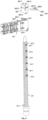
- the phase shifter C1 is linked with the phase shifter C2 through a push component D1; the phase shifter C3 is linked with the phase shifter C4 through a push component D2; the phase shifter C5 is linked with the phase shifter C6 through a push component D3; the phase shifter C7 is linked with the phase shifter C8 through a push component D4; the phase shifter C9 is linked with the phase shifter C10 through a push component D5; the phase shifter C11 is linked with the phase shifter C12 through a push component D6.
- the reflecting plate of this solution is bent to form a first reflecting surface, a second reflecting surface, a third reflecting surface and a fourth reflecting surface.
- Each of the first reflecting surface, the second reflecting surface, the third reflecting surface and the fourth reflecting surface is equipped with eight oscillator units, so that four sectors can be formed in use. The directions of beams formed by different sectors are different.
- the oscillator units on each sector of this solution can be combined to form 4T4R, so as to meet the requirements for higher-frequency signal communication in the process of mobile communication.
- this solution also includes the oscillator units B1 to B8, the oscillator units B1 to B4 can be combined to form 4T4R, and the oscillator units B5 to B8 can also be combined to form 4T4R; this not only meets the requirements for low-frequency signal communication in the process of mobile communication, but also makes this solution meet the requirements for multi-frequency and multi-beam in use.
- the oscillator units combined to form the same 4T4R are divided into two groups according to the mounting layout of the oscillator units; one group directly faces the first electromagnetic lens, and the other group directly faces the second electromagnetic lens; each group of oscillator units is connected with one phase shifter, and two phase shifters correspondingly connected to two groups of oscillator units combined to form the 4T4R are linked through a same push component.
- beam downtilt angles of the two groups of oscillator units combined to form the 4T4R can be adjusted in use, so as to change a signal coverage area of each sector.
- a signal of each oscillator unit is emitted in a form of plane-like wave after passing through the electromagnetic lens, which can improve the directionality of the beam.
- adjusting the beam downtilt angle of the oscillator unit by controlling the phase shifter requires less motion space, which is conducive to reducing products' volume, and this way also makes the control on beam direction of the oscillator unit more accurate and more convenient to operate.
- the push component D1, the push component D2, the push component D3, the push component D4, the push component D5 and the push component D6 are all slidably mounted on the mounting plate; a sliding direction of each of the push component D1, the push component D2, the push component D3, the push component D4, the push component D5 and the push component D6 relative to the mounting plate is parallel to the central axis of the first electromagnetic lens; each of the push component D1, the push component D2, the push component D3, the push component D4, the push component D5 and the push component D6 is driven by a separate screw drive mechanism to slide relative to the mounting plate; each screw drive mechanism comprises a screw, a sliding block, a guide rod and a drive unit; both ends of the screw are rotationally mounted on the mounting plate, and a central axis of the screw is parallel to the central axis of the first electromagnetic lens; both ends of the guide rod are mounted on the mounting plate, and a central axis of the guide rod is parallel to the central axis of the screw; a screw hole and
- a connecting rod is also mounted on the sliding block of the screw drive mechanism; the connecting rod is slidably mounted on the mounting plate, and a sliding direction of the connecting rod relative to the mounting plate is parallel to the central axis of the first electromagnetic lens; one end of each of the push components D1 to D6 is connected to one end of the connecting rod of its corresponding screw drive mechanism through a connector, and the other end of the connecting rod is connected to a scale.
- the screw drive mechanism further comprises a limiting assembly, the limiting assembly comprises a sheathing component and a clamping component, the sheathing component is provided with a sheathing hole, a clamping ring groove is formed on an outer circumferential surface of the sheathing component, the sheathing component is further provided with a through hole connecting the clamping ring groove to the wall of the sheathing hole, and the sheathing component is sheathed on the screw through its sheathing hole; a plurality of pin holes are set on the screw, and the plurality of pin holes are arranged along the axis of the screw; the clamping component is a semi-enclosed ring-shaped component, a locating pin is formed on the inner surface of the clamping component, the clamping component is clamped in the clamping ring groove of the sheathing component, and a locating pin of the clamping component is inserted through the through hole of the sheathing component into the pin hole of the screw; a first blocking part is arranged on the screw, and
- a cut surface is formed on the outer circumferential surface of the screw, and the pin hole is formed on the cut surface of the screw;
- the sheathing hole of the sheathing component is an irregularly-shaped hole with a plane, the through hole of the sheathing component penetrates the plane in the sheathing hole, and the plane in the sheathing hole of the sheathing component is wedged with the cut surface of the screw.
- the present invention may also include a main control module, wherein the drive units of the screw drive mechanism for driving the push component D1 to slide relative to the mounting plate, the screw drive mechanism for driving the push component D2 to slide relative to the mounting plate, the screw drive mechanism for driving the push component D3 to slide relative to the mounting plate, the screw drive mechanism for driving the push component D4 to slide relative to the mounting plate, the screw drive mechanism for driving the push component D5 to slide relative to the mounting plate, and the screw drive mechanism for driving the push component D6 to slide relative to the mounting plate is electrically connected to the main control module; the main control module, the screw drive mechanism for driving the push component D1 to slide relative to the mounting plate, the screw drive mechanism for driving the push component D2 to slide relative to the mounting plate, the screw drive mechanism for driving the push component D3 to slide relative to the mounting plate, the screw drive mechanism for driving the push component D4 to slide relative to the mounting plate, the screw drive mechanism for driving the push component D5 to slide relative to the mounting plate, and the screw drive mechanism for driving the push component D
- each of oscillator units A1 to A32 has an operating frequency of 1710MHz to 2610MHz
- each of the oscillator units B1 to B8 has an operating frequency of 698MHZ to 960MHz.
- first reflecting surface and the second reflecting surface form an angle F1 of 130° to 150°
- second reflecting surface and the third reflecting surface form an angle F2 of 130° to 150°
- third reflecting surface and the fourth reflecting surface form an angle F3 of 130° to 150°.
- the straight line L1 and the straight line L2 have a spacing K1 of 110 ⁇ 5mm
- the straight line L2 and the straight line L3 have a spacing K2 of 140 ⁇ 5mm
- the straight line L3 and the straight line L4 have a spacing K3 of 110 ⁇ 5mm
- the straight line L5 and the straight line L6 have a spacing K4 of 290 ⁇ 5mm.
- the mounting plate is bent to form a first mounting surface, a second mounting surface and a third mounting surface; each of the first mounting surface, the second mounting surface, and the third mounting surface is set to face the reflecting plate; the first mounting surface and the second mounting surface form an angle H1 of 130° to 150°, and the second mounting surface and the third mounting surface form an angle H2 of 130° to 150°; the phase shifters C1, C2, C9 and C10 are all mounted on the first mounting surface, the phase shifters C3, C4, C5 and C6 are all mounted on the second mounting surface, and the phase shifters C7, C8, C11 and C12 are all mounted on the third mounting surface.
- phase shifters C1 to C12 are all PCB sliding sector phase shifters or metal cavity phase shifters.
- this solution may also include an outer shell; the outer shell includes a cylindrical component, a first end cover and a second end cover; the first end cover is covered and fixed on one opening of the cylindrical component, and the second end cover is covered and fixed on the other opening of the cylindrical component, so that the first end cover, the cylindrical component and the second end cover constitute a chamber; the first electromagnetic lens, the second electromagnetic lens, the mounting plate, the reflecting plate, the oscillator units A1 to A32, the oscillator units B1 to B8, the phase shifters C1 to C12, and the screw drive mechanism are all mounted in the chamber; and the scale on the screw drive mechanism extends out of the chamber through the first end cover.
- the outer shell includes a cylindrical component, a first end cover and a second end cover; the first end cover is covered and fixed on one opening of the cylindrical component, and the second end cover is covered and fixed on the other opening of the cylindrical component, so that the first end cover, the cylindrical component and the second end cover constitute a chamber; the first electromagnetic lens, the second electromagnetic lens, the mounting
- a pull component G1 and a pull component G2 are fixed on the push component D1, a pull component G3 and a pull component G4 are fixed on the push component D2, a pull component G5 and a pull component G6 are fixed on the push component D3, a pull component G7 and a pull component G8 are fixed on the push component D4, a pull component G9 and a pull component G10 are fixed on the push component D5, and a pull component G11 and a pull component G12 are fixed on the push component D6; each of the pull components G1 to G12 is provided with an elongated hole; the elongated hole on the pull component G1 is nested with the cylinder on the sliding block of the phase shifter C1; the elongated hole on the pull component G2 is nested with the cylinder on the sliding block of the phase shifter C2; the elongated hole on the pull component G3 is nested with the cylinder on the sliding block of the phase shifter C3; the elongated hole on the pull
- the invention has advantages of simple structure, scientific design, small size, flexible setting of beam direction, and being able to meet the requirements of an MIMO technology for the number of channels.
- 1 represents a first electromagnetic lens
- 2 represents a second electromagnetic lens
- 3 represents a mounting plate
- 31 represents a first mounting surface
- 32 represents a second mounting surface
- 33 represents a third mounting surface
- 4 represents a reflecting plate
- 41 represents a first reflecting surface
- 42 represents a second reflecting surface
- 43 represents a third reflecting surface
- 44 represents a fourth reflecting surface
- 51 represents an oscillator unit A1
- 52 represents an oscillator unit A2
- 53 represents an oscillator unit A3
- 54 represents an oscillator unit A4
- 55 represents an oscillator unit A5
- 56 represents an oscillator unit A6
- 57 represents an oscillator unit A7
- 58 represents an oscillator unit A8
- 59 represents an oscillator unit A9
- 510 represents an oscillator unit A10
- 511 represents an oscillator unit A11
- 512 represents an oscillator unit A12
- 513 represents an oscillator unit A13
- 514 represents an oscillator
- a multi-frequency and multi-beam independent electrically adjustable antenna of this embodiment includes a first electromagnetic lens 1, a second electromagnetic lens 2, a mounting plate 3, a reflecting plate 4, an oscillator unit A1 51, an oscillator unit A2 52, an oscillator unit A3 53, an oscillator unit A4 54, an oscillator unit A5 55, an oscillator unit A6 56, an oscillator unit A7 57, an oscillator unit A8 58, an oscillator unit A9 59, an oscillator unit A10 510, an oscillator unit A11 511, an oscillator unit A12 512, an oscillator unit A13 513, an oscillator unit A14 514, an oscillator unit A15 515, an oscillator unit A16 516, an oscillator unit A17 517, an oscillator unit A18 518,
- the reflecting plate 4 is bent to form a first reflecting surface 41, a second reflecting surface 42, a third reflecting surface 43 and a fourth reflecting surface 44.
- the first reflecting surface 41, the second reflecting surface 42, the third reflecting surface 43 and the fourth reflecting surface 44 are successively connected to form a wrap angle.
- Both the first electromagnetic lens 1 and the second electromagnetic lens 2 are cylindrical lenses.
- the first electromagnetic lens 1 and the second electromagnetic lens 2 are both partially positioned in the wrap angle.
- a central axis of the first electromagnetic lens 1 is collinear with a central axis of the second electromagnetic lens 2.
- the first electromagnetic lens 1, the second electromagnetic lens 2, the reflecting plate 4 and the mounting plate 3 are fixed relative to each other, and the mounting plate 3 is on a side of the reflecting plate 4 facing away from the first electromagnetic lens 1 and the second electromagnetic lens 2,.
- the oscillator unit B1 61, the oscillator unit B2 62, the oscillator unit B3 63, the oscillator unit B4 64, the oscillator unit B5 65, the oscillator unit B6 66, the oscillator unit B7 67 and the oscillator unit B8 68 are oscillators with a same operating frequency.
- Each of the oscillator units A1 to A32 has an operating frequency of 1710MHz to 2610MHz, and each of the oscillator units B1 to B8 has an operating frequency of 698MHZ to 960MHz.
- the oscillator unit A1 51, the oscillator unit A2 52, the oscillator unit A3 53, the oscillator unit A4 54, the oscillator unit A5 55, the oscillator unit A6 56, the oscillator unit A7 57 and the oscillator unit A8 58 are all mounted on the first reflecting surface 41.
- the oscillator unit A1 51, the oscillator unit A2 52, the oscillator unit A3 53, the oscillator unit A4 54, the oscillator unit A5 55, the oscillator unit A6 56, the oscillator unit A7 57 and the oscillator unit A8 58 are arranged in sequence along a straight line L1.
- Each of the oscillator unit A1 51, the oscillator unit A2 52, the oscillator unit A3 53 and the oscillator unit A4 54 is set to have a signal receiving and transmitting direction towards the first electromagnetic lens 1 and perpendicular to the central axis of the first electromagnetic lens 1.
- Each of the oscillator unit A5 55, the oscillator unit A6 56, the oscillator unit A7 57 and the oscillator unit A8 58 is set to have a signal receiving and transmitting direction towards the second electromagnetic lens 2 and perpendicular to the central axis of the second electromagnetic lens 2.
- the oscillator unit A9 59, the oscillator unit A10 510, the oscillator unit A11 511, the oscillator unit A12 512, the oscillator unit A13 513, the oscillator unit A14 514, the oscillator unit A15 515 and the oscillator unit A16 516 are all mounted on the second reflecting surface 42.
- the oscillator unit A9 59, the oscillator unit A10 510, the oscillator unit A11 511, the oscillator unit A12 512, the oscillator unit A13 513, the oscillator unit A14 514, the oscillator unit A15 515 and the oscillator unit A16 516 are arranged in sequence along a straight line L2.
- Each of the oscillator unit A9 59, the oscillator unit A10 510, the oscillator unit A11 511 and the oscillator unit A12 512 is set to have a signal receiving and transmitting direction towards the first electromagnetic lens 1 and perpendicular to the central axis of the first electromagnetic lens 1.
- Each of the oscillator unit A13 513, the oscillator unit A14 514, the oscillator unit A15 515 and the oscillator unit A16 516 is set to have a signal receiving and transmitting direction towards the second electromagnetic lens 2 and perpendicular to the central axis of the second electromagnetic lens 2.
- the oscillator unit A17 517, the oscillator unit A18 518, the oscillator unit A19 519, the oscillator unit A20 520, the oscillator unit A21 521, the oscillator unit A22 522, the oscillator unit A23 523 and the oscillator unit A24 524 are all mounted on the third reflecting surface 43.
- the oscillator unit A17 517, the oscillator unit A18 518, the oscillator unit A19 519, the oscillator unit A20 520, the oscillator unit A21 521, the oscillator unit A22 522, the oscillator unit A23 523 and the oscillator unit A24 524 are arranged in sequence along a straight line L3.
- Each of the oscillator unit A17 517, the oscillator unit A18 518, the oscillator unit A19 519 and the oscillator unit A20 520 is set to have a signal receiving and transmitting direction towards the first electromagnetic lens 1 and perpendicular to the central axis of the first electromagnetic lens 1.
- Each of the oscillator unit A21 521, the oscillator unit A22 522, the oscillator unit A23 523 and the oscillator unit A24 524 is set to have a signal receiving and transmitting direction towards the second electromagnetic lens 2 and perpendicular to the central axis of the second electromagnetic lens 2.
- the oscillator unit A25 525, the oscillator unit A26 526, the oscillator unit A27 527, the oscillator unit A28 528, the oscillator unit A29 529, the oscillator unit A30 530, the oscillator unit A31 531 and the oscillator unit A32 532 are all mounted on the fourth reflecting surface 44.
- the oscillator unit A25 525, the oscillator unit A26 526, the oscillator unit A27 527, the oscillator unit A28 528, the oscillator unit A29 529, the oscillator unit A30 530, the oscillator unit A31 531 and the oscillator unit A32 532 are arranged in sequence along a straight line L4.
- Each of the oscillator unit A25 525, the oscillator unit A26 526, the oscillator unit A27 527 and the oscillator unit A28 528 is set to have a signal receiving and transmitting direction towards the first electromagnetic lens 1 and perpendicular to the central axis of the first electromagnetic lens 1.
- Each of the oscillator unit A29 529, the oscillator unit A30 530, the oscillator unit A31 531 and the oscillator unit A32 532 is set to have a signal receiving and transmitting direction towards the second electromagnetic lens 2 and perpendicular to the central axis of the second electromagnetic lens 2.
- the oscillator unit B1 61, the oscillator unit B2 62, the oscillator unit B3 63 and the oscillator unit B4 64 are all mounted on the reflecting plate 4.
- the oscillator unit B1 61, the oscillator unit B2 62, the oscillator unit B3 63 and the oscillator unit B4 64 are arranged in sequence along a side L5 formed by connecting the first reflecting surface 41 and the second reflecting surface 42.
- Each of the oscillator unit B1 61 and the oscillator unit B2 62 is set to have a signal receiving and transmitting direction towards the first electromagnetic lens 1 and perpendicular to the central axis of the first electromagnetic lens 1.
- Each of the oscillator unit B3 63 and the oscillator unit B4 64 is set to have a signal receiving and transmitting direction towards the second electromagnetic lens 2 and perpendicular to the central axis of the second electromagnetic lens 2.
- the oscillator unit B5 65, the oscillator unit B6 66, the oscillator unit B7 67 and the oscillator unit B8 68 are all mounted on the reflecting plate 4.
- the oscillator unit B5 65, the oscillator unit B6 66, the oscillator unit B7 67 and the oscillator unit B8 68 are arranged in sequence along a side L6 formed by connecting the third reflecting surface 43 and the fourth reflecting surface 44.
- the straight lines L1, L2, L3, and L4 and the sides L5 and L6 are all parallel to the central axis of the first electromagnetic lens.
- the straight line L1 and the straight line L2 have a spacing K1 of 110mm; the straight line L2 and the straight line L3 have a spacing K2 of 140mm; the straight line L3 and the straight line L4 have a spacing K3 of 110mm; and the straight line L5 and the straight line L6 have a spacing K4 of 290mm.
- Each of the oscillator unit B5 65 and the oscillator unit B6 66 is set to have a signal receiving and transmitting direction towards the first electromagnetic lens 1 and perpendicular to the central axis of the first electromagnetic lens 1.
- Each of the oscillator unit B7 67 and the oscillator unit B8 68 is set to have a signal receiving and transmitting direction towards the second electromagnetic lens 2 and perpendicular to the central axis of the second electromagnetic lens 2.
- phase shifter C1 71, the phase shifter C2 72, the phase shifter C3 73, the phase shifter C4 74, the phase shifter C5 75, the phase shifter C6 76, the phase shifter C7 77, the phase shifter C8 78, the phase shifter C9 79, the phase shifter C10 710, the phase shifter C11 711, and the phase shifter C12 712 are all mounted on the mounting plate 3.
- phase shifter C1 71, the phase shifter C2 72, the phase shifter C3 73, the phase shifter C4 74, the phase shifter C5 75, the phase shifter C6 76, the phase shifter C7 77, the phase shifter C8 78, the phase shifter C9 79, the phase shifter C10 710, the phase shifter C11 711, and the phase shifter C12 712 are all PCB sliding sector phase shifters.
- the oscillator unit A1 51, the oscillator unit A2 52, the oscillator unit A3 53 and the oscillator unit A4 54 are all electrically connected to an output end of the phase shifter C1 71 to form 2T2R, and the oscillator unit A5 55, the oscillator unit A6 56, the oscillator unit A7 57 and the oscillator unit A8 58 are all electrically connected to an output end of the phase shifter C2 72 to form 2T2R, so that the oscillator unit A1 51, the oscillator unit A2 52, the oscillator unit A3 53, the oscillator unit A4 54, the oscillator unit A5 55, the oscillator unit A6 56, the oscillator unit A7 57 and the oscillator unit A8 58 form 4T4R.
- the oscillator unit A9 59, the oscillator unit A10 510, the oscillator unit A11 511 and the oscillator unit A12 512 are all electrically connected to an output end of the phase shifter C3 73 to form 2T2R, and the oscillator unit A13 513, the oscillator unit A14 514, the oscillator unit A15 515 and the oscillator unit A16 516 are all electrically connected to an output end of the phase shifter C4 74 to form 2T2R, so that the oscillator unit A9 59, the oscillator unit A10 510, the oscillator unit A11 511, the oscillator unit A12 512, the oscillator unit A13 513, the oscillator unit A14 514, the oscillator unit A15 515 and the oscillator unit A16 516 form 4T4R.
- the oscillator unit A17 517, the oscillator unit A18 518, the oscillator unit A19 519 and the oscillator unit A20 520 are all electrically connected to an output end of the phase shifter C5 75 to form 2T2R, and the oscillator unit A21 521, the oscillator unit A22 522, the oscillator unit A23 523 and the oscillator unit A24 524 are all electrically connected to an output end of the phase shifter C6 76 to form 2T2R, so that the oscillator unit A17 517, the oscillator unit A18 518, the oscillator unit A19 519, the oscillator unit A20 520, the oscillator unit A21 521, the oscillator unit A22 522, the oscillator unit A23 523, the oscillator unit A24 524 form 4T4R.
- the oscillator unit A25 525, the oscillator unit A26 526, the oscillator unit A27 527, the oscillator unit A28 528 are all electrically connected to an output end of the phase shifter C7 77 to form 2T2R
- the oscillator unit A29 529, the oscillator unit A30 530, the oscillator unit A31 531 and the oscillator unit A32 532 are all electrically connected to an output end of the phase shifter C8 78 to form 2T2R, so that the oscillator unit A25 525, the oscillator unit A26 526, the oscillator unit A27 527, the oscillator unit A28 528, the oscillator unit A29 529, the oscillator unit A30 530, the oscillator unit A31 531 and the oscillator unit A32 532 form 4T4R.
- the oscillator unit B 1 61 and the oscillator unit B2 62 are both electrically connected to an output end of the phase shifter C9 79 to form 2T2R
- the oscillator unit B3 63 and the oscillator unit B4 64 are both electrically connected to an output end of the phase shifter C10 710 to form 2T2R, so that the oscillator unit B1 61, the oscillator unit B2 62, the oscillator unit B3 63 and the oscillator unit B4 64 form 4T4R.
- the oscillator unit B5 65 and the oscillator unit B6 66 are both electrically connected to an output end of the phase shifter C11 711 to form 2T2R
- the oscillator unit B7 67 and the oscillator unit B8 68 are both electrically connected to an output end of the phase shifter C12 712 to form 2T2R, so that the oscillator unit B5 65, the oscillator unit B6 66, the oscillator unit B7 67 and the oscillator unit B8 68 form 4T4R.
- the phase shifter C1 71 is linked with the phase shifter C2 72 through a push component D1 81.
- the phase shifter C3 73 is linked with the phase shifter C4 74through a push component D2 82.
- the phase shifter C5 75 is linked with the phase shifter C6 76 through a push component D3 83.
- the phase shifter C7 77 is linked with the phase shifter C8 78 through a push component D4 84.
- the phase shifter C9 79 is linked with the phase shifter C10 710 through a push component D5 85.
- the phase shifter C11 711 is linked with the phase shifter C12 712 through a push component D6 86.
- the push component D1 81, the push component D2 82, the push component D3 83, the push component D4 84, the push component D5 85 and the push component D6 86 are all slidably mounted on the mounting plate 3.
- a sliding direction of each of the push component D1 81, the push component D2 82, the push component D3 83, the push component D4 84, the push component D5 85 and the push component D6 86 relative to the mounting plate 3 is parallel to the central axis of the first electromagnetic lens 1.
- Each of the push component D1 81, the push component D2 82, the push component D3 83, the push component D4 84, the push component D5 85 and the push component D6 86 is driven by a separate screw drive mechanism 9 to slide relative to the mounting plate 3.
- Each screw drive mechanism 9 includes a screw 91, a sliding block 92, a guide rod 93 and a drive unit 94.
- Both ends of the screw 91 are rotationally mounted on the mounting plate 3, and a central axis of the screw 91 is parallel to the central axis of the first electromagnetic lens 1.
- Both ends of the guide rod 93 are mounted on the mounting plate 3, and a central axis of the guide rod 93 is parallel to the central axis of the screw 91.
- a screw hole 921 and a guide hole 922 are formed on the sliding block 92, the screw hole 921 of the sliding block 92 is connected to threads of the screw 91, and the guide hole 922 of the sliding block 92 is fitted with the guide rod 93.
- the drive unit 94 is mounted on the mounting plate 3 and used to drive the screw 91 to rotate.
- Each of the push component D1 81, the push component D2 82, the push component D3 83, the push component D4 84, the push component D5 85 and the push component D6 86 is connected with a sliding block 92 of its corresponding screw drive mechanism 9.
- Two ends of the screw 91 of the screw drive mechanism 9 are respectively mounted on a rotating mounting base 30 rotationally.
- the rotating mounting base 30 is fixed on the mounting plate 3.
- Each of the push component D1 81, the push component D2 82, the push component D3 83, the push component D4 84, the push component D5 85 and the push component D6 86 is slidably mounted on the mounting plate 3 through four sliding mounting bases 20.
- a phase shifter is arranged between every two sliding mounting bases 20, so that a sliding sheet of the phase shifter can slide more smoothly when it is pushed.
- the push component D1 81, the push component D2 82, the push component D3 83, the push component D4 84, the push component D5 85 and the push component D6 86 are all rods, and a sliding hole for the rod to pass through is formed on the sliding mounting base 20.
- a connecting rod 95 is also mounted on the sliding block 92 of the screw drive mechanism 9.
- the connecting rod 95 is slidably mounted on the mounting plate 3.
- a sliding direction of the connecting rod 95 relative to the mounting plate 3 is parallel to the central axis of the first electromagnetic lens 1.
- One end of each of the push components D1 81 to D6 86 is connected to one end of the connecting rod 95 of its corresponding screw drive mechanism 9 through a connector 96, and the other end of the connecting rod 95 is connected to a scale 97.
- the adjustment ranges of the phase shifter C1 71, the phase shifter C2 72, the phase shifter C3 73, the phase shifter C4 74, the phase shifter C5 75, the phase shifter C6 76, the phase shifter C7 77, the phase shifter C8 78, the phase shifter C9 79, the phase shifter C10 710, the phase shifter C11 711 and the phase shifter C12 712 can be determined by observing the scale 97 in use.
- the connecting rod 95 of each screw drive mechanism 9 is mounted on the mounting plate 3 through two sliding mounting components 40. A through hole for the connecting rod 95 to pass through is formed on the sliding mounting component 40.
- the sliding block 92 of the screw drive mechanism 9 is between two sliding mounting components 40, so that the sliding block 92 slides more smoothly.
- the screw drive mechanism 9 further includes a limiting assembly 98 to limit the maximum motion amplitude of the sliding block 92 on the screw 91, so that the swing amplitude of the sliding sheet 71 on each of the phase shifter C1, the phase shifter C2 72, the phase shifter C3 73, the phase shifter C4 74, the phase shifter C5 75, the phase shifter C6 76, the phase shifter C7 77, the phase shifter C8 78, the phase shifter C9 79, the phase shifter C10 710, the phase shifter C11 711 and the phase shifter C12 712 is limited.
- a limiting assembly 98 to limit the maximum motion amplitude of the sliding block 92 on the screw 91, so that the swing amplitude of the sliding sheet 71 on each of the phase shifter C1, the phase shifter C2 72, the phase shifter C3 73, the phase shifter C4 74, the phase shifter C5 75, the phase shifter C6 76, the phase shifter C
- the limiting assembly 98 includes a sheathing component 981 and a clamping component 982.
- the sheathing component 981 is provided with a sheathing hole 9811.
- a clamping ring groove 9812 is formed on an outer circumferential surface of the sheathing component 981.
- the sheathing component 981 is further provided with a through hole 9813 connecting the clamping ring groove 9812 to the wall of the sheathing hole 9811, and the sheathing component 981 is sheathed on the screw 91 through its sheathing hole 9811.
- a plurality of pin holes 911 are set on the screw 91, and the plurality of pin holes 911 are arranged along the axis of the screw 91.
- the clamping component 982 is a semi-enclosed ring-shaped component.
- a locating pin 9821 is formed on the inner surface of the clamping component 982.
- the clamping component 982 is clamped in the clamping ring groove 9812 of the sheathing component 981, and the locating pin 9821 of the clamping component 982 is inserted through the through hole 9813 of the sheathing component 981 into the pin hole 911 of the screw 91.
- a first blocking part 912 is arranged on the screw 91, and the sliding block 92 is positioned between the limiting assembly 98 and the first blocking part 912.
- a second blocking part 9814 is formed on an end face of the sheathing component 981 facing the sliding block 92.
- a first pressing-against part 923 cooperating with the first blocking part 912 is formed on an end face of the sliding block 92 facing the first blocking part 912
- a second pressing-against part 924 cooperating with the second blocking part 9814 is formed on an end face of the sliding block 92 facing the sheathing component 981.
- the screw 91 is positively rotated to move the sliding block 92 on the screw 91 closer to the limiting assembly 98, until the second pressing-against part 924 of the sliding block 92 presses against the second blocking part 9814 on the sheathing component 981 and the sliding block 92 stops moving, which can prevent the screw 91 from continuing to rotate to cause the sliding block 92 to lock the screw 91 cooperating with the sheathing component 981.
- the screw 91 can be prevented from being damaged by excessive torque at the moment when the screw 91 is reversely rotated to move the sliding block 92 farther away from the sheathing component 981.
- the screw 91 can be reversely rotated to move the sliding block 92 on the screw 9 closer to the first blocking part 912, until the first pressing-against part 923 of the sliding block 92 presses against the first blocking part 912 and the sliding block 92 stops moving, which allows the sliding block 92 not to separate from the screw 91.
- a cut surface 913 is formed on the outer circumferential surface of the screw 91.
- the pin hole 911 is formed on the cut surface 913 of the screw 91.
- the sheathing hole 9811 of the sheathing component 981 is an irregularly-shaped hole with a plane 9815, the through hole 9813 of the sheathing component 981 penetrates the plane 9815 in the sheathing hole 9811, and the plane 9815 in the sheathing hole 9811 of the sheathing component 981 is wedged with the cut surface 913 of the screw 91.
- the multi-frequency and multi-beam independent electrically adjustable antenna also includes a main control module 50.
- the drive units of the screw drive mechanism 9 for driving the push component D1 81 to slide relative to the mounting plate 3, the screw drive mechanism for driving the push component D2 82 to slide relative to the mounting plate 3, the screw drive mechanism for driving the push component D3 83 to slide relative to the mounting plate 3, the screw drive mechanism for driving the push component D4 84 to slide relative to the mounting plate 3, the screw drive mechanism for driving the push component D5 85 to slide relative to the mounting plate 3, and the screw drive mechanism for driving the push component D6 86 to slide relative to the mounting plate 3 are all electrically connected with the main control module 50.
- the main control module 50, the screw drive mechanism 9 for driving the push component D1 81 to slide relative to the mounting plate 3, the screw drive mechanism for driving the push component D2 82 to slide relative to the mounting plate 3, the screw drive mechanism for driving the push component D3 83 to slide relative to the mounting plate 3, the screw drive mechanism for driving the push component D4 84 to slide relative to the mounting plate 3, the screw drive mechanism for driving the push component D5 85 to slide relative to the mounting plate 3, and the screw drive mechanism for driving the push component D6 86 to slide relative to the mounting plate 3 constitute a module with a volume of 3100cm 3 .
- the first reflecting surface 41 and the second reflecting surface 42 form an angle F1 of 140°
- the second reflecting surface 42 and the third reflecting surface 43 form an angle F2 of 140°
- the third reflecting surface 43 and the fourth reflecting surface 44 form an angle F3 of 140°.
- the mounting plate 3 is bent to form a first mounting surface 31, a second mounting surface 32 and a third mounting surface 33. Each of the first mounting surface 31, the second mounting surface 32, and the third mounting surface 33 is set to face the reflecting plate 4.
- the first mounting surface 31 and the second mounting surface 32 form an angle H1 of 138°
- the second mounting surface 32 and the third mounting surface 33 form an angle H2 of 138°.
- the phase shifter C1 71, the phase shifter C2 72, the phase shifter C9 79 and the phase shifter C10 710 are all mounted on the first mounting surface 31, the phase shifter C3 73, the phase shifter C4 74, the phase shifter C5 75 and the phase shifter C6 76 are all mounted on the second mounting surface 32, and the phase shifter C7 77, the phase shifter C8 78, the phase shifter C11 711 and the phase shifter C12 712 are all mounted on the third mounting surface 33.
- the multi-frequency and multi-beam independent electrically adjustable antenna further includes an outer shell 10.
- the outer shell 10 includes a cylindrical component 101, a first end cover 102 and a second end cover 103.
- the first end cover 102 is covered and fixed on one opening of the cylindrical component 101, and the second end cover 103 is covered and fixed on the other opening of the cylindrical component 101, so that the first end cover 102, the cylindrical component 101 and the second end cover 103 constitute a chamber; the first electromagnetic lens 1, the second electromagnetic lens 2, the mounting plate 3, the reflecting plate 4, the oscillator units A1 51 to A32 532, the oscillator units B1 61 to B8 68, the phase shifters C1 71 to C12 712, and the screw drive mechanism 9 are all mounted in the chamber.
- the scale 97 on the screw drive mechanism 9 extends out of the chamber through the first end cover 102.
- a pull component G1 811 and a pull component G2 812 are fixed on the push component D1 81
- a pull component G3 821 and a pull component G4 822 are fixed on the push component D2 82
- a pull component G5 831 and a pull component G6 832 are fixed on the push component D3 83
- a pull component G7 841 and a pull component G8 842 are fixed on the push component D4 84
- a pull component G9 851 and a pull component G10 852 are fixed on the push component D5 85
- a pull component G11 861 and a pull component G12 862 are fixed on the push component D6 86.
- Each of the pull components G1 811 to G12 862 is provided with an elongated hole.
- the elongated hole on the pull component G1 811 is nested with the cylinder on the sliding block of the phase shifter C1 71.
- the elongated hole on the pull component G2 812 is nested with the cylinder on the sliding block of the phase shifter C2 72.
- the elongated hole on the pull component G3 821 is nested with the cylinder on the sliding block of the phase shifter C3 73.
- the elongated hole on the pull component G4 822 is nested with the cylinder on the sliding block of the phase shifter C4 74.
- the elongated hole on the pull component G5 831 is nested with the cylinder on the sliding block of the phase shifter C5 75.
- the elongated hole on the pull component G6 832 is nested with the cylinder on the sliding block of the phase shifter C6 76.
- the elongated hole on the pull component G7 841 is nested with the cylinder on the sliding block of the phase shifter C7 77.
- the elongated hole on the pull component G8 842 is nested with the cylinder on the sliding block of the phase shifter C8 78.
- the elongated hole on the pull component G9 851 is nested with the cylinder on the sliding block of the phase shifter C9 79; the elongated hole on the pull component G10 852 is nested with the cylinder on the sliding block of the phase shifter C10 710.
- the elongated hole on the pull component G11 861 is nested with the cylinder on the sliding block of the phase shifter C11 711.
- the elongated hole on the pull component G12 862 is nested with the cylinder on the sliding block of the phase shifter C12 712.
- phase shifter C1 71, the phase shifter C2 72, the phase shifter C3 73, the phase shifter C4 74, the phase shifter C5 75, the phase shifter C6 76, the phase shifter C7 77, the phase shifter C8 78, the phase shifter C9 79, the phase shifter C10 710, the phase shifter C11 711 and the phase shifter C12 712 in this embodiment are all the metal cavity phase shifters 60 as shown in Fig. 9 .
- a metal cavity phase shifter 60 involves better performance indicators of antennas when used.
Landscapes
- Physics & Mathematics (AREA)
- Electromagnetism (AREA)
- Engineering & Computer Science (AREA)
- Computer Networks & Wireless Communication (AREA)
- Aerials With Secondary Devices (AREA)
- Variable-Direction Aerials And Aerial Arrays (AREA)
Claims (8)
- Mehrfrequenz- und mehrstrahl-unabhängige, elektrisch verstellbare Antenne, umfassend:eine erste elektromagnetische Linse (1), eine zweite elektromagnetische Linse (2), eine Montageplatte (3), eine Reflexionsplatte (4), Oszillatoreinheiten A1 (51) bis A32 (532), Oszillatoreinheiten B1 (61) bis B8 (68) sowie Phasenschieber C1 bis C12; wobeidie Reflexionsplatte (4) gebogen ist, um eine erste Reflexionsoberfläche (41), eine zweite Reflexionsoberfläche (42), eine dritte Reflexionsoberfläche (43) und eine vierte Reflexionsoberfläche (44) zu bilden, wobei die erste Reflexionsoberfläche (41), die zweite Reflexionsoberfläche (42), die dritte Reflexionsoberfläche (43) und die vierte Reflexionsoberfläche (44) nacheinander zu einem Wickelwinkel verbunden sind;wobei die erste elektromagnetische Linse (1) und die zweite elektromagnetische Linse (2) beide zylindrische Linsen sind, wobei die erste elektromagnetische Linse (1) und die zweite elektromagnetische Linse (2) teilweise im Wickelwinkel positioniert sind, und wobei eine Mittelachse der ersten elektromagnetischen Linse (1) kollinearer mit der Mittelachse der zweiten elektromagnetischen Linse (2) ist;wobei die erste elektromagnetische Linse (1), die zweite elektromagnetische Linse (2), die Reflexionsplatte (4) und die Montageplatte (3) relativ zueinander befestigt sind, und wobei die Montageplatte (3) auf einer Seite der Reflexionsplatte (4), die von der ersten elektromagnetischen Linse (1) und der zweiten elektromagnetischen Linse (2) abgewandt ist;wobei die Oszillatoreinheiten A1 (51) bis A32 (532) sind Oszillatoren mit derselben Betriebsfrequenz, und wobei die Oszillatoreinheiten B1 (61) bis B8 (68) Oszillatoren mit derselben Betriebsfrequenz sind; wobei die Betriebsfrequenz jeder der Oszillatoreinheiten A1 (51) bis A32 (532) höher als die Betriebsfrequenz jeder der Oszillatoreinheiten B1 (61) bis B8 (68) ist;wobei die Oszillatoreinheiten A1 (51) bis A8 (58) alle auf der ersten Reflexionsoberfläche (41) montiert sind, wobei die Oszillatoreinheiten A1 (51) bis A8 (58) in Reihenfolge entlang einer geraden Linie L1 angeordnet sind, wobei jede der Oszillatoreinheiten A1 (51) bis A4 (54) derart eingestellt ist, dass sie eine Signalempfangs- und Senderrichtung in Richtung der ersten elektromagnetischen Linse (1) und senkrecht zur Mittelachse der ersten elektromagnetischen Linse (1) aufweist, und wobei jede der Oszillatoreinheiten A5 (55) bis A8 (58) derart eingestellt ist, dass sie eine Signalempfangs- und Senderrichtung in Richtung der zweiten elektromagnetischen Linse (2) und senkrecht zur Mittelachse der zweiten elektromagnetischen Linse (2) aufweist;wobei die Oszillatoreinheiten A9 (59) bis A16 (516) alle auf der zweiten Reflexionsoberfläche (42) montiert sind, wobei die Oszillatoreinheiten A9 (59) bis A16 (516) in Reihenfolge entlang einer geraden Linie L2 angeordnet sind, wobei jede der Oszillatoreinheiten A9 (59) bis A12 (512) derart eingestellt ist, dass sie eine Signalempfangs- und Senderrichtung in Richtung der ersten elektromagnetischen Linse (1) und senkrecht zur Mittelachse der ersten elektromagnetischen Linse (1) aufweist, und wobei jede der Oszillatoreinheiten A13 bis A16 derart eingestellt ist, dass sie eine Signalempfangs- und Senderrichtung in Richtung der zweiten elektromagnetischen Linse (2) und senkrecht zur Mittelachse der zweiten elektromagnetischen Linse (2) aufweist;wobei die Oszillatoreinheiten A17 (517) bis A24 (524) alle auf der dritten Reflexionsoberfläche (43) montiert sind, wobei die Oszillatoreinheiten A17 (517) bis A24 (524) in Reihenfolge entlang einer geraden Linie L3 angeordnet sind, wobei jede der Oszillatoreinheiten A17 (517) bis A20 (520) derart eingestellt ist, dass sie eine Signalempfangs- und Senderrichtung in Richtung der ersten elektromagnetischen Linse (1) und senkrecht zur Mittelachse der ersten elektromagnetischen Linse (1) aufweist, und wobei jede der Oszillatoreinheiten A21 (521) bis A24 (524) derart eingestellt ist, dass sie eine Signalempfangs- und Senderrichtung in Richtung der zweiten elektromagnetischen Linse (2) und senkrecht zur Mittelachse der zweiten elektromagnetischen Linse (2) aufweist;wobei die Oszillatoreinheiten A25 (525) bis A32 (532) alle auf der vierten Reflexionsoberfläche (44) montiert sind, wobei die Oszillatoreinheiten A25 (525) bis A32 (532) in Reihenfolge entlang einer geraden Linie L4 angeordnet sind, wobei jede der Oszillatoreinheiten A25 (525) bis A28 (528) derart eingestellt ist, dass sie eine Signalempfangs- und Senderrichtung in Richtung der ersten elektromagnetischen Linse (1) und senkrecht zur Mittelachse der ersten elektromagnetischen Linse (1) aufweist, und wobei jede der Oszillatoreinheiten A29 (529) bis A32 (532) derart eingestellt ist, dass sie eine Signalempfangs- und Senderrichtung in Richtung der zweiten elektromagnetischen Linse (2) und senkrecht zur Mittelachse der zweiten elektromagnetischen Linse (2) aufweist;wobei die Oszillatoreinheiten B1 (61) bis B4 (64) alle auf der Reflexionsplatte (41) montiert sind, wobei die Oszillatoreinheiten B1 (61) bis B4 (64) in Reihenfolge entlang einer Seite L5 angeordnet sind, die durch Verbinden der ersten Reflexionsoberfläche (41) und der zweiten Reflexionsoberfläche (42) ausgebildet ist, wobei jede der Oszillatoreinheiten B1 (61) und B2 (62) derart eingestellt ist, dass sie eine Signalempfangs- und Senderrichtung in Richtung der ersten elektromagnetischen Linse (1) und senkrecht zur Mittelachse der ersten elektromagnetischen Linse (1) aufweist, und wobei jede der Oszillatoreinheiten B3 (63) und B4 (64) derart eingestellt ist, dass sie eine Signalempfangs- und Senderrichtung in Richtung der zweiten elektromagnetischen Linse (2) und senkrecht zur Mittelachse der zweiten elektromagnetischen Linse (2) aufweist;wobei die Oszillatoreinheiten B5 (65) bis B8 (68) alle auf der Reflexionsplatte (41) montiert sind, wobei die Oszillatoreinheiten B5 (65) bis B8 (68) in Reihenfolge entlang einer Seite L6 angeordnet sind, die durch Verbinden der dritten Reflexionsoberfläche (43) und der vierten Reflexionsoberfläche (44) ausgebildet ist, wobei die geraden Linien L1, L2, L3 und L4 sowie die Seiten L5 und L6 alle parallel zur Mittelachse der ersten elektromagnetischen Linse (1) sind, wobei jede der Oszillatoreinheiten B5 (65) und B6 (66) derart eingestellt ist, dass sie eine Signalempfangs- und Senderrichtung in Richtung der ersten elektromagnetischen Linse (1) und senkrecht zur Mittelachse der ersten elektromagnetischen Linse (1) aufweist, und wobei jede der Oszillatoreinheiten B7 (67) und B8 (68) derart eingestellt ist, dass sie eine Signalempfangs- und Senderrichtung in Richtung der zweiten elektromagnetischen Linse (2) und senkrecht zur Mittelachse der zweiten elektromagnetischen Linse (2) aufweist;wobei die Phasenschieber C1 bis C12 alle auf der Montageplatte (3) montiert sind, wobei die Oszillatoreinheiten A1 (51) bis A4 (54) alle elektrisch an ein Ausgangsende des Phasenschiebers C1 (71) angeschlossen sind, um 2 Transmit 2 Receive, 2T2R, Multiple Input Multiple Output, MIMO, Operation zu bilden, wobei die Oszillatoreinheiten A5 (55) bis A8 (58) alle elektrisch an ein Ausgangsende des Phasenschiebers C2 (72) angeschlossen sind, um 2T2R zu bilden, so dass die Oszillatoreinheiten A1 (51) bis A8 (58) 4T4R bilden; wobei die Oszillatoreinheiten A9 (59) bis A12 (512) alle elektrisch an ein Ausgangsende des Phasenschiebers C3 (73) angeschlossen sind, um 2T2R zu bilden, wobei die Oszillatoreinheiten A13 (513) bis A16 (516) alle elektrisch an ein Ausgangsende des Phasenschiebers C4 (74) angeschlossen sind, um 2T2R zu bilden, so dass die Oszillatoreinheiten A9 (59) bis A16 (516) 4T4R bilden; wobei die Oszillatoreinheiten A17 (517) bis A20 (520) alle elektrisch an ein Ausgangsende des Phasenschiebers C5 (75) angeschlossen sind, um 2T2R zu bilden, wobei die Oszillatoreinheiten A21 (521) bis A24 (524) alle elektrisch an ein Ausgangsende des Phasenschiebers C6 (76) angeschlossen sind, um 2T2R zu bilden, so dass die Oszillatoreinheiten A17 (517) bis A24 (524) 4T4R bilden;wobei die Oszillatoreinheiten A25 (525) bis A28 (528) alle elektrisch an ein Ausgangsende des Phasenschiebers C7 (77) angeschlossen sind, um 2T2R zu bilden, wobei die Oszillatoreinheiten A29 (529) bis A32 (532) alle elektrisch an ein Ausgangsende des Phasenschiebers C8 (78) angeschlossen sind, um 2T2R zu bilden, so dass die Oszillatoreinheiten A25 (525) bis A32 (532) 4T4R bilden; wobei die Oszillatoreinheiten B1 (61) und B2 (62) beide elektrisch an ein Ausgangsende des Phasenschiebers C9 (79) angeschlossen sind, um 2T2R zu bilden, wobei die Oszillatoreinheiten B3 (63) und B4 (64) beide elektrisch an ein Ausgangsende des Phasenschiebers C10 (710) angeschlossen sind, um 2T2R zu bilden, so dass die Oszillatoreinheiten B1 (61) bis B4 (64) 4T4R bilden; wobei die Oszillatoreinheiten B5 (65) und B6 (66) beide elektrisch an ein Ausgangsende des Phasenschiebers C11 (711) angeschlossen sind, um 2T2R zu bilden, wobei die Oszillatoreinheiten B7 (67) und B8 (68) beide elektrisch an ein Ausgangsende des Phasenschiebers C12 (712) angeschlossen sind, um 2T2R zu bilden, so dass die Oszillatoreinheiten B5 (65) bis B8 (68) 4T4R bilden;wobei der Phasenschieber C1 (71) mit dem Phasenschieber C2 (72) über eine Schubkomponente D1 (81) verbunden ist; wobei der Phasenschieber C3 (73) mit dem Phasenschieber C4 (74) über eine Schubkomponente D2 (82) verbunden ist; wobei der Phasenschieber C5 (75) mit dem Phasenschieber C6 (76) über eine Schubkomponente D3 (83) verbunden ist; wobei der Phasenschieber C7 (77) mit dem Phasenschieber C8 (78) über eine Schubkomponente D4 (84) verbunden ist; wobei der Phasenschieber C9 (79) mit dem Phasenschieber C10 (710) über eine Schubkomponente D5 (85) verbunden ist; wobei der Phasenschieber C11 (711) mit dem Phasenschieber C12 (712) über eine Schubkomponente D6 (86) verbunden ist; wobei die Schubkomponente D1 (87), die Schubkomponente D2 (88), die Schubkomponente D3 (83), die Schubkomponente D4 (84), die Schubkomponente D5 (85) und die Schubkomponente D6 (86) alle schiebbar auf der Montageplatte (3) montiert sind;wobei eine Gleitrichtung der jeder der Schubkomponente D1 (81), der Schubkomponente D2 (82), der Schubkomponente D3 (83), der Schubkomponente D4 (84), der Schubkomponente D5 (85) und der Schubkomponente D6 (86) gegenüber der Montageplatte (3) parallel zur Mittelachse der ersten elektromagnetischen Linse (1) ist; wobei jede der Schubkomponente D1 (81), der Schubkomponente D2 (82), der Schubkomponente D3 (83), der Schubkomponente D4 (84), der Schubkomponente D5 (85) und der Schubkomponente D6 (86) durch einen separaten Schraubenantriebsmechanismus (9) angetrieben wird, um relativ zur Montageplatte (3) zu schieben; wobei jeder Schraubenantriebsmechanismus (9) umfasst eine Schraube (91), einen Schiebeblock (92), eine Führungsstange (93) und eine Antriebseinheit (94); wobei beide Enden der Schraube (91) drehbar auf der Montageplatte (3) montiert sind, und wobei eine Mittelachse der Schraube (91) parallel zur Mittelachse der ersten elektromagnetischen Linse (1) ist; wobei beide Enden der Führungsstange (93) auf der Montageplatte (3) montiert sind, und wobei eine Mittelachse der Führungsstange (93) parallel zur Mittelachse der Schraube (91) ist; wobei ein Schraubenloch (921) und ein Führungsloch (922) auf dem Schiebeblock (92) ausgebildet sind, wobei das Schraubenloch (921) des Schiebeblocks (92) mit den Gewinde der Schraube (91) verbunden ist, und wobei das Führungsloch (922) des Schiebeblocks (92) mit der Führungsstange (93) versehen ist; wobei die Antriebseinheit (94) auf der Montageplatte (3) montiert und dient zur Drehung der Schraube (91); wobei jede der Schubkomponente D1 (81), der Schubkomponente D2 (82), der Schubkomponente D3 (83), der Schubkomponente D4 (84), der Schubkomponente D5 (85) und der Schubkomponente D6 (86) mit einem Schiebeblock (92) seines entsprechenden Schraubenantriebsmechanismus (9) verbunden ist;wobei der Schraubenantriebsmechanismus (9) ferner eine Begrenzungsanordnung (98) umfasst, wobei die Begrenzungsanordnung (98) eine Mantelkomponente (981) und eine Klemmkomponente (982) umfasst, wobei die Mantelkomponente (981) mit einem Mantelloch (9811) versehen ist, wobei eine Klemmringnut (9812) auf einer äußeren Umfangsoberfläche der Mantelkomponente (981) ausgebildet ist, wobei die Mantelkomponente (981) ferner mit einem Durchgangsloch (9813) versehen ist, das die Klemmringnut (9812) mit der Wand des Mantellochs (9811) verbindet, und wobei die Mantelkomponente (981) durch sein Mantelloch (9811) auf der Schraube (91) ummantelt ist; wobei eine Vielzahl von Stiftlöchern (911) auf der Schraube (91) angebracht sind, und wobei die Vielzahl von Stiftlöchern (911) entlang der Achse der Schraube (91) angeordnet sind; wobei die Klemmkomponente (982) ist eine halbgeschlossene ringförmige Komponente, wobei ein Positionierungsstift (9821) auf der Innenfläche der Klemmkomponente (982) ausgebildet ist, wobei die Klemmkomponente (982) in der Klemmringnut (9812) der Mantelkomponente (981) eingespannt ist, und wobei ein Positionierungsstift (9821) der Klemmkomponente (982) durch das Durchgangsloch (9813) der Mantelkomponente (981) in das Stiftloch (911) der Schraube (91) eingesetzt ist; wobei ein erster Blockierteil (912) auf der Schraube (91) angeordnet ist, und wobei der Schiebeblock (92) zwischen der Begrenzungsanordnung (98) und dem ersten Blockierteil (912) positioniert ist; wobei ein zweiter Blockierteil (9814) auf der Endfläche der Mantelkomponente (981), das dem Schiebeblock (92) zugewandt ist, und wobei ein erster Anpressteil (923), der mit dem ersten Blockierteil (912) zusammenwirkt, an einer Endfläche des Schiebeblocks (92) ausgebildet ist, die dem ersten Blockierteil (912) zugewandt ist, und wobei ein zweiter Anpressteil (924), der mit dem zweiten Blockierteil (9814) zusammenwirkt, an einer Endfläche des Schiebeblocks (92) ausgebildet ist, die der Mantelkomponente (981) zugewandt ist.
- Mehrfrequenz- und mehrstrahl-unabhängige, elektrisch verstellbare Antenne gemäß Anspruch 1 , wobei auch eine Verbindungsstange (95) auf dem Schiebeblock (92) des Schraubenantriebsmechanismus (9) montiert ist; wobei die Verbindungsstange (95) verschiebbar auf der Montageplatte (3) montiert ist, und wobei eine Gleitrichtung der Verbindungsstange (95) gegenüber der Montageplatte (3) parallel zur Mittelachse der ersten elektromagnetischen Linse (1) ist; wobei ein Ende jeder der Schubkomponenten D1 bis D6 über einen Stecker (96) an ein Ende der Verbindungsstange (95) seines entsprechenden Schraubenantriebsmechanismus (9) verbunden ist, und wobei das andere Ende der Verbindungsstange (95) an eine Skala (97) verbunden ist.
- Mehrfrequenz- und mehrstrahl-unabhängige, elektrisch verstellbare Antenne gemäß Anspruch 1, wobei eine Schnittfläche (913) auf der Außenumfangfläche der Schraube (91), und wobei das Stiftloch (911) auf der Schnittfläche (913) der Schraube (91) ausgebildet ist; wobei das Mantelloch (9811) der Mantelkomponente (981) ein unregelmäßig geformtes Loch mit einer Ebene (9815) ist, wobei das Durchgangsloch (9813) der Mantelkomponente (981) die Ebene (9815) im Mantelloch (9811) durchdringt, und wobei die Ebene (9815) im Mantelloch (9811) der Mantelkomponente (981) mit der Schnittfläche (913) der Schraube (91) verkeilt ist.
- Mehrfrequenz- und mehrstrahl-unabhängige, elektrisch verstellbare Antenne gemäß Anspruch 1, die weiterhin ein Hauptsteuermodul (50) umfasst, wobei die Antriebseinheiten (94) des Schraubantriebsmechanismus (9) zum Antreiben der Schubkomponente D1 (81), so dass sie relativ zur Montageplatte (3) gleitet, des Schraubantriebsmechanismus (9) zum Antreiben der Schubkomponente D2 (82), so dass sie relativ zur Montageplatte (3) gleitet, des Schraubantriebsmechanismus (9) zum Antreiben der Schubkomponente D3 (83), so dass sie relativ zur Montageplatte (3) gleitet, des Schraubantriebsmechanismus (9) zum Antreiben der Schubkomponente D4 (84), so dass sie relativ zur Montageplatte (3) gleitet, des Schraubantriebsmechanismus (9) zum Antreiben der Schubkomponente D5 (85), so dass sie relativ zur Montageplatte (3) gleitet, und des Schraubantriebsmechanismus (9) zum Antreiben der Schubkomponente D6 (86), so dass sie relativ zur Montageplatte (3) gleitet, alle elektrisch mit dem Hauptsteuermodul (50) verbunden sind; wobei das Hauptsteuermodul (50), der Schraubantriebsmechanismus (9) zum Antreiben der Schubkomponente D1 (81), so dass sie relativ zur Montageplatte (3) gleitet, der Schraubantriebsmechanismus (9) zum Antreiben der Schubkomponente D2 (82), so dass sie relativ zur Montageplatte (3) gleitet, der Schraubenantriebsmechanismus (9) zum Antreiben der Schubkomponente D3 (83), so dass sie relativ zur Montageplatte (3) gleitet, der Schraubenantriebsmechanismus (9) zum Antreiben der Schubkomponente D4 (84), so dass sie relativ zur Montageplatte (3) gleitet, der Schraubenantriebsmechanismus (9) zum Antreiben der Schubkomponente D5 (85), so dass sie relativ zur Montageplatte (3) gleitet, und der Schraubenantriebsmechanismus (9) zum Antreiben der Schubkomponente D6 (86), so dass sie relativ zur Montageplatte (3) gleitet, bilden ein Modul mit einem Volumen von 3000 cm3 bis 3200 cm3.
- Mehrfrequenz- und mehrstrahl-unabhängige, elektrisch verstellbare Antenne gemäß Anspruch 1, wobei jede der Oszillatoreinheiten A1 (51) bis A32 (532) eine Betriebsfrequenz von 1710 MHz bis 2610 MHz aufweist, und wobei jede der Oszillatoreinheiten B1 (61) bis B8 (68) eine Betriebsfrequenz von 698 MHz bis 960 MHz aufweist.
- Mehrfrequenz- und mehrstrahl-unabhängige, elektrisch verstellbare Antenne gemäß Anspruch 1, wobei die erste Reflexionsoberfläche (41) und die zweite Reflexionsoberfläche (42) einen Winkel F1 von 130° bis 150° bilden, wobei die zweite Reflexionsoberfläche (42) und die dritte Reflexionsoberfläche (43) einen Winkel F2 von 130° bis 150° bilden, und wobei die dritte Reflexionsoberfläche (43) und die vierte Reflexionsoberfläche (44) einen Winkel F3 von 130° bis 150° bilden.
- Mehrfrequenz- und mehrstrahl-unabhängige, elektrisch verstellbare Antenne gemäß Anspruch 6, wobei die gerade Linie L1 und die gerade Linie L2 einen Abstand K1 von 110 ± 5 mm aufweisen, wobei die gerade Linie L2 und die gerade Linie L3 einen Abstand K2 von 140 ± 5 mm aufweisen, wobei die gerade Linie L3 und die gerade Linie L4 einen Abstand K3 von 110 ± 5 mm aufweisen, und wobei die gerade Linie L5 und die gerade Linie L6 einen Abstand K4 von 290 ± 5 mm aufweisen.
- Mehrfrequenz- und mehrstrahl-unabhängige, elektrisch verstellbare Antenne gemäß Anspruch 1, wobei die Montageplatte (3) gebogen ist, um eine erste Montagefläche (31), eine zweite Montagefläche (32) und eine dritte Montagefläche (33) zu bilden; wobei jede der ersten Montagefläche (31), der zweiten Montagefläche (32) und der dritten Montagefläche (33) ist so ausgerichtet, dass sie der Reflexionsplatte (4) zugewandt ist; wobei die erste Montagefläche (31) und die zweite Montagefläche (32) einen Winkel H1 von 130° bis 150° bilden, und wobei die zweite Montagefläche (32) und die dritte Montagefläche (33) einen Winkel H2 von 130° bis 150° bilden; wobei die Phasenschieber C1, C2, C9 und C10 alle auf der ersten Montagefläche (31) montiert sind, wobei die Phasenschieber C3, C4, C5 und C6 alle auf der zweiten Montagefläche (32) montiert sind, und wobei die Phasenschieber C7, C8, C11 und C12 alle auf der dritten Montagefläche (33) montiert sind.
Applications Claiming Priority (1)
| Application Number | Priority Date | Filing Date | Title |
|---|---|---|---|
| CN202210571599.9A CN114665270B (zh) | 2022-05-25 | 2022-05-25 | 一种多频多波束独立电调天线 |
Publications (3)
| Publication Number | Publication Date |
|---|---|
| EP4293822A1 EP4293822A1 (de) | 2023-12-20 |
| EP4293822B1 true EP4293822B1 (de) | 2024-12-11 |
| EP4293822C0 EP4293822C0 (de) | 2024-12-11 |
Family
ID=82037709
Family Applications (1)
| Application Number | Title | Priority Date | Filing Date |
|---|---|---|---|
| EP23173157.1A Active EP4293822B1 (de) | 2022-05-25 | 2023-05-12 | Mehrfrequenz- und mehrstrahlige unabhängige elektrisch verstellbare antenne |
Country Status (6)
| Country | Link |
|---|---|
| US (1) | US11901648B2 (de) |
| EP (1) | EP4293822B1 (de) |
| JP (1) | JP7320804B1 (de) |
| KR (1) | KR102580963B1 (de) |
| CN (1) | CN114665270B (de) |
| PH (1) | PH12023050224A1 (de) |
Families Citing this family (2)
| Publication number | Priority date | Publication date | Assignee | Title |
|---|---|---|---|---|
| CN116581516B (zh) * | 2023-04-18 | 2023-12-05 | 佛山市粤海信通讯有限公司 | 一种电调透镜天线 |
| WO2025113776A1 (en) * | 2023-11-28 | 2025-06-05 | Huawei Technologies Co., Ltd. | Multi-beam antenna |
Family Cites Families (17)
| Publication number | Priority date | Publication date | Assignee | Title |
|---|---|---|---|---|
| KR100685313B1 (ko) * | 2003-04-30 | 2007-02-22 | 주식회사 엘지텔레콤 | 안테나 복사패턴의 수평빔과 수직빔 조절을 위한 안테나시스템과 이를 이용한 안테나 시스템의 제어방법 |
| KR100638514B1 (ko) * | 2003-12-31 | 2006-10-25 | 주식회사 케이엠더블유 | 평판 인쇄형 다이폴 방사소자가 어레이된 이중편파 안테나및 그의 제어시스템 |
| KR101869756B1 (ko) * | 2012-04-12 | 2018-06-21 | 주식회사 케이엠더블유 | 이동통신 시스템용 가변 빔 제어 안테나 |
| CN103219590B (zh) * | 2013-03-29 | 2015-07-15 | 京信通信技术(广州)有限公司 | 可实现隔离度调节的移相装置 |
| CN112909494B (zh) * | 2016-09-07 | 2024-01-26 | 康普技术有限责任公司 | 适合用于蜂窝和其它通信系统的多频带多波束透镜式天线 |
| WO2020041467A1 (en) * | 2018-08-24 | 2020-02-27 | Commscope Technologies Llc | Lensed base station antennas having staggered vertical arrays for azimuth beam width stabilization |
| US10288909B1 (en) * | 2018-10-26 | 2019-05-14 | Spy Eye, Llc | Contact lens data transceiver |
| CN112970149B (zh) * | 2018-11-07 | 2024-05-24 | 康普技术有限责任公司 | 具有提供龙伯透镜的阶梯近似的功能结构的带透镜基站天线 |
| CN209691956U (zh) | 2019-05-30 | 2019-11-26 | 摩比科技(深圳)有限公司 | 集束型天线 |
| JP2022174353A (ja) * | 2019-10-30 | 2022-11-24 | Dic株式会社 | 液晶組成物、液晶素子及びアンテナ |
| CN113394563A (zh) * | 2020-03-13 | 2021-09-14 | 康普技术有限责任公司 | 机械传动机构和基站天线 |
| CN111900553B (zh) * | 2020-07-14 | 2021-04-16 | 苏州海天新天线科技有限公司 | 双垂直极化人工介质圆柱多波束天线 |
| CN112886276A (zh) * | 2021-01-14 | 2021-06-01 | 广州司南技术有限公司 | 多波束透镜天线和有源透镜天线系统 |
| CN216161931U (zh) * | 2021-08-10 | 2022-04-01 | 佛山市粤海信通讯有限公司 | 一种多频多波束龙伯球透镜天线 |
| CN215896724U (zh) * | 2021-09-26 | 2022-02-22 | 佛山市粤海信通讯有限公司 | 一种可实现电调的多频多波束透镜天线 |
| CN114050399B (zh) * | 2021-12-01 | 2026-01-27 | 苏州立讯技术有限公司 | 基站天线 |
| CN216529317U (zh) | 2021-12-31 | 2022-05-13 | 佛山市粤海信通讯有限公司 | 一种波束独立调节的多波束透镜天线 |
-
2022
- 2022-05-25 CN CN202210571599.9A patent/CN114665270B/zh active Active
-
2023
- 2023-05-12 EP EP23173157.1A patent/EP4293822B1/de active Active
- 2023-05-15 KR KR1020230062333A patent/KR102580963B1/ko active Active
- 2023-05-16 US US18/318,494 patent/US11901648B2/en active Active
- 2023-05-16 JP JP2023081054A patent/JP7320804B1/ja active Active
- 2023-05-25 PH PH1/2023/050224A patent/PH12023050224A1/en unknown
Also Published As
| Publication number | Publication date |
|---|---|
| PH12023050224A1 (en) | 2024-03-11 |
| CN114665270A (zh) | 2022-06-24 |
| EP4293822A1 (de) | 2023-12-20 |
| US20230387592A1 (en) | 2023-11-30 |
| JP2023174564A (ja) | 2023-12-07 |
| CN114665270B (zh) | 2022-09-02 |
| US11901648B2 (en) | 2024-02-13 |
| KR102580963B1 (ko) | 2023-09-20 |
| EP4293822C0 (de) | 2024-12-11 |
| JP7320804B1 (ja) | 2023-08-04 |
Similar Documents
| Publication | Publication Date | Title |
|---|---|---|
| EP4293822A1 (de) | Mehrfrequenz- und mehrstrahlige unabhängige elektrisch verstellbare antenne | |
| US11984634B2 (en) | Base station antennas having double-sided phase shifters and/or rearwardly extending phase shifters and associated phase shifter assemblies | |
| US11515623B2 (en) | Metrocell antennas configured for mounting around utility poles | |
| CN113517554B (zh) | 一种低剖面宽频带双圆极化相控阵天线系统 | |
| US20040061653A1 (en) | Dynamically variable beamwidth and variable azimuth scanning antenna | |
| US20130342390A1 (en) | Satellite vsat antenna for transmitting/receiving multiple polarized waves | |
| US10615488B2 (en) | Linkage mechanism for base station antenna | |
| KR20050004043A (ko) | 안테나 장치 | |
| US11742575B2 (en) | Remote electronic tilt base station antennas having adjustable RET linkages | |
| US20220037783A1 (en) | Phase shifter transmission device | |
| CN109687146B (zh) | 电调天线的下倾角调节装置及电调天线 | |
| EP4183001B1 (de) | Antennenvorrichtung mit verbesserter strahlungsrichtcharakteristik | |
| CN108987929A (zh) | 一种微波毫米波紧凑相控阵天线系统 | |
| CN114050399A (zh) | 基站天线 | |
| US11349184B2 (en) | Phase shifter including first and second boards having rails thereon and configured to be rotatable with respect to each other and an antenna formed therefrom | |
| US7688268B1 (en) | Multi-band antenna system | |
| KR101567122B1 (ko) | 밀폐형 반사경 안테나 마운트 | |
| CN214203988U (zh) | 一种基站天线 | |
| JPH03151701A (ja) | アレイアンテナ | |
| US5596338A (en) | Multifunction antenna assembly | |
| CN115395249A (zh) | 多频天线及通信设备 | |
| TH2301003070A (th) | สายอากาศที่ปรับได้ด้วยไฟฟ้าอย่างอิสระแบบหลายความถี่และหลายลำแสง | |
| EP4687215A1 (de) | Strahlungselemente für mehrband-basisstationsantennen mit hohlraumphasenschiebern und zugehörige lineararrayanordnungen und basisstationsantennen | |
| CN224264265U (zh) | 辐射组件及天线 | |
| US20260128512A1 (en) | Phase shifter |
Legal Events
| Date | Code | Title | Description |
|---|---|---|---|
| PUAI | Public reference made under article 153(3) epc to a published international application that has entered the european phase |
Free format text: ORIGINAL CODE: 0009012 |
|
| STAA | Information on the status of an ep patent application or granted ep patent |
Free format text: STATUS: REQUEST FOR EXAMINATION WAS MADE |
|
| STAA | Information on the status of an ep patent application or granted ep patent |
Free format text: STATUS: EXAMINATION IS IN PROGRESS |
|
| 17P | Request for examination filed |
Effective date: 20230512 |
|
| AK | Designated contracting states |
Kind code of ref document: A1 Designated state(s): AL AT BE BG CH CY CZ DE DK EE ES FI FR GB GR HR HU IE IS IT LI LT LU LV MC ME MK MT NL NO PL PT RO RS SE SI SK SM TR |
|
| 17Q | First examination report despatched |
Effective date: 20231204 |
|
| GRAP | Despatch of communication of intention to grant a patent |
Free format text: ORIGINAL CODE: EPIDOSNIGR1 |
|
| STAA | Information on the status of an ep patent application or granted ep patent |
Free format text: STATUS: GRANT OF PATENT IS INTENDED |
|
| INTG | Intention to grant announced |
Effective date: 20240711 |
|
| GRAS | Grant fee paid |
Free format text: ORIGINAL CODE: EPIDOSNIGR3 |
|
| GRAA | (expected) grant |
Free format text: ORIGINAL CODE: 0009210 |
|
| STAA | Information on the status of an ep patent application or granted ep patent |
Free format text: STATUS: THE PATENT HAS BEEN GRANTED |
|
| AK | Designated contracting states |
Kind code of ref document: B1 Designated state(s): AL AT BE BG CH CY CZ DE DK EE ES FI FR GB GR HR HU IE IS IT LI LT LU LV MC ME MK MT NL NO PL PT RO RS SE SI SK SM TR |
|
| REG | Reference to a national code |
Ref country code: GB Ref legal event code: FG4D |
|
| REG | Reference to a national code |
Ref country code: CH Ref legal event code: EP |
|
| REG | Reference to a national code |
Ref country code: IE Ref legal event code: FG4D |
|
| REG | Reference to a national code |
Ref country code: DE Ref legal event code: R096 Ref document number: 602023001311 Country of ref document: DE |
|
| U01 | Request for unitary effect filed |
Effective date: 20250102 |
|
| U07 | Unitary effect registered |
Designated state(s): AT BE BG DE DK EE FI FR IT LT LU LV MT NL PT RO SE SI Effective date: 20250114 |
|
| PG25 | Lapsed in a contracting state [announced via postgrant information from national office to epo] |
Ref country code: HR Free format text: LAPSE BECAUSE OF FAILURE TO SUBMIT A TRANSLATION OF THE DESCRIPTION OR TO PAY THE FEE WITHIN THE PRESCRIBED TIME-LIMIT Effective date: 20241211 |
|
| PG25 | Lapsed in a contracting state [announced via postgrant information from national office to epo] |
Ref country code: ES Free format text: LAPSE BECAUSE OF FAILURE TO SUBMIT A TRANSLATION OF THE DESCRIPTION OR TO PAY THE FEE WITHIN THE PRESCRIBED TIME-LIMIT Effective date: 20241211 |
|
| PG25 | Lapsed in a contracting state [announced via postgrant information from national office to epo] |
Ref country code: NO Free format text: LAPSE BECAUSE OF FAILURE TO SUBMIT A TRANSLATION OF THE DESCRIPTION OR TO PAY THE FEE WITHIN THE PRESCRIBED TIME-LIMIT Effective date: 20250311 |
|
| PG25 | Lapsed in a contracting state [announced via postgrant information from national office to epo] |
Ref country code: GR Free format text: LAPSE BECAUSE OF FAILURE TO SUBMIT A TRANSLATION OF THE DESCRIPTION OR TO PAY THE FEE WITHIN THE PRESCRIBED TIME-LIMIT Effective date: 20250312 |
|
| PG25 | Lapsed in a contracting state [announced via postgrant information from national office to epo] |
Ref country code: RS Free format text: LAPSE BECAUSE OF FAILURE TO SUBMIT A TRANSLATION OF THE DESCRIPTION OR TO PAY THE FEE WITHIN THE PRESCRIBED TIME-LIMIT Effective date: 20250311 |
|
| U1N | Appointed representative for the unitary patent procedure changed after the registration of the unitary effect |
Representative=s name: METIDA; LT |
|
| U20 | Renewal fee for the european patent with unitary effect paid |
Year of fee payment: 3 Effective date: 20250507 |
|
| PG25 | Lapsed in a contracting state [announced via postgrant information from national office to epo] |
Ref country code: SM Free format text: LAPSE BECAUSE OF FAILURE TO SUBMIT A TRANSLATION OF THE DESCRIPTION OR TO PAY THE FEE WITHIN THE PRESCRIBED TIME-LIMIT Effective date: 20241211 |
|
| PG25 | Lapsed in a contracting state [announced via postgrant information from national office to epo] |
Ref country code: PL Free format text: LAPSE BECAUSE OF FAILURE TO SUBMIT A TRANSLATION OF THE DESCRIPTION OR TO PAY THE FEE WITHIN THE PRESCRIBED TIME-LIMIT Effective date: 20241211 |
|
| PG25 | Lapsed in a contracting state [announced via postgrant information from national office to epo] |
Ref country code: IS Free format text: LAPSE BECAUSE OF FAILURE TO SUBMIT A TRANSLATION OF THE DESCRIPTION OR TO PAY THE FEE WITHIN THE PRESCRIBED TIME-LIMIT Effective date: 20250411 |
|
| PG25 | Lapsed in a contracting state [announced via postgrant information from national office to epo] |
Ref country code: SK Free format text: LAPSE BECAUSE OF FAILURE TO SUBMIT A TRANSLATION OF THE DESCRIPTION OR TO PAY THE FEE WITHIN THE PRESCRIBED TIME-LIMIT Effective date: 20241211 |
|
| PG25 | Lapsed in a contracting state [announced via postgrant information from national office to epo] |
Ref country code: CZ Free format text: LAPSE BECAUSE OF FAILURE TO SUBMIT A TRANSLATION OF THE DESCRIPTION OR TO PAY THE FEE WITHIN THE PRESCRIBED TIME-LIMIT Effective date: 20241211 |
|
| PLBE | No opposition filed within time limit |
Free format text: ORIGINAL CODE: 0009261 |
|
| STAA | Information on the status of an ep patent application or granted ep patent |
Free format text: STATUS: NO OPPOSITION FILED WITHIN TIME LIMIT |
|
| 26N | No opposition filed |
Effective date: 20250912 |
|
| PG25 | Lapsed in a contracting state [announced via postgrant information from national office to epo] |
Ref country code: MC Free format text: LAPSE BECAUSE OF FAILURE TO SUBMIT A TRANSLATION OF THE DESCRIPTION OR TO PAY THE FEE WITHIN THE PRESCRIBED TIME-LIMIT Effective date: 20241211 |
|
| PG25 | Lapsed in a contracting state [announced via postgrant information from national office to epo] |
Ref country code: IE Free format text: LAPSE BECAUSE OF NON-PAYMENT OF DUE FEES Effective date: 20250512 |