EP4183001B1 - Antennenvorrichtung mit verbesserter strahlungsrichtcharakteristik - Google Patents
Antennenvorrichtung mit verbesserter strahlungsrichtcharakteristik Download PDFInfo
- Publication number
- EP4183001B1 EP4183001B1 EP20743669.2A EP20743669A EP4183001B1 EP 4183001 B1 EP4183001 B1 EP 4183001B1 EP 20743669 A EP20743669 A EP 20743669A EP 4183001 B1 EP4183001 B1 EP 4183001B1
- Authority
- EP
- European Patent Office
- Prior art keywords
- array
- radiating
- antenna device
- radiating element
- signal
- Prior art date
- Legal status (The legal status is an assumption and is not a legal conclusion. Google has not performed a legal analysis and makes no representation as to the accuracy of the status listed.)
- Active
Links
Images


Classifications
-
- H—ELECTRICITY
- H01—ELECTRIC ELEMENTS
- H01Q—ANTENNAS, i.e. RADIO AERIALS
- H01Q21/00—Antenna arrays or systems
- H01Q21/06—Arrays of individually energised antenna units similarly polarised and spaced apart
- H01Q21/08—Arrays of individually energised antenna units similarly polarised and spaced apart the units being spaced along or adjacent to a rectilinear path
-
- H—ELECTRICITY
- H01—ELECTRIC ELEMENTS
- H01Q—ANTENNAS, i.e. RADIO AERIALS
- H01Q19/00—Combinations of primary active antenna elements and units with secondary devices, e.g. with quasi-optical devices, for giving the antenna a desired directional characteristic
- H01Q19/10—Combinations of primary active antenna elements and units with secondary devices, e.g. with quasi-optical devices, for giving the antenna a desired directional characteristic using reflecting surfaces
-
- H—ELECTRICITY
- H01—ELECTRIC ELEMENTS
- H01Q—ANTENNAS, i.e. RADIO AERIALS
- H01Q21/00—Antenna arrays or systems
- H01Q21/0006—Particular feeding systems
-
- H—ELECTRICITY
- H01—ELECTRIC ELEMENTS
- H01Q—ANTENNAS, i.e. RADIO AERIALS
- H01Q3/00—Arrangements for changing or varying the orientation or the shape of the directional pattern of the waves radiated from an antenna or antenna system
- H01Q3/26—Arrangements for changing or varying the orientation or the shape of the directional pattern of the waves radiated from an antenna or antenna system varying the relative phase or relative amplitude of energisation between two or more active radiating elements; varying the distribution of energy across a radiating aperture
- H01Q3/30—Arrangements for changing or varying the orientation or the shape of the directional pattern of the waves radiated from an antenna or antenna system varying the relative phase or relative amplitude of energisation between two or more active radiating elements; varying the distribution of energy across a radiating aperture varying the relative phase between the radiating elements of an array
- H01Q3/34—Arrangements for changing or varying the orientation or the shape of the directional pattern of the waves radiated from an antenna or antenna system varying the relative phase or relative amplitude of energisation between two or more active radiating elements; varying the distribution of energy across a radiating aperture varying the relative phase between the radiating elements of an array by electrical means
- H01Q3/36—Arrangements for changing or varying the orientation or the shape of the directional pattern of the waves radiated from an antenna or antenna system varying the relative phase or relative amplitude of energisation between two or more active radiating elements; varying the distribution of energy across a radiating aperture varying the relative phase between the radiating elements of an array by electrical means with variable phase-shifters
-
- H—ELECTRICITY
- H01—ELECTRIC ELEMENTS
- H01Q—ANTENNAS, i.e. RADIO AERIALS
- H01Q1/00—Details of, or arrangements associated with, antennas
- H01Q1/12—Supports; Mounting means
- H01Q1/22—Supports; Mounting means by structural association with other equipment or articles
- H01Q1/24—Supports; Mounting means by structural association with other equipment or articles with receiving set
- H01Q1/241—Supports; Mounting means by structural association with other equipment or articles with receiving set used in mobile communications, e.g. GSM
- H01Q1/246—Supports; Mounting means by structural association with other equipment or articles with receiving set used in mobile communications, e.g. GSM specially adapted for base stations
-
- H—ELECTRICITY
- H01—ELECTRIC ELEMENTS
- H01Q—ANTENNAS, i.e. RADIO AERIALS
- H01Q21/00—Antenna arrays or systems
- H01Q21/24—Combinations of antenna units polarised in different directions for transmitting or receiving circularly and elliptically polarised waves or waves linearly polarised in any direction
-
- H—ELECTRICITY
- H01—ELECTRIC ELEMENTS
- H01Q—ANTENNAS, i.e. RADIO AERIALS
- H01Q5/00—Arrangements for simultaneous operation of antennas on two or more different wavebands, e.g. dual-band or multi-band arrangements
- H01Q5/40—Imbricated or interleaved structures; Combined or electromagnetically coupled arrangements, e.g. comprising two or more non-connected fed radiating elements
-
- H—ELECTRICITY
- H01—ELECTRIC ELEMENTS
- H01Q—ANTENNAS, i.e. RADIO AERIALS
- H01Q9/00—Electrically-short antennas having dimensions not more than twice the operating wavelength and consisting of conductive active radiating elements
- H01Q9/04—Resonant antennas
- H01Q9/16—Resonant antennas with feed intermediate between the extremities of the antenna, e.g. centre-fed dipole
- H01Q9/28—Conical, cylindrical, cage, strip, gauze, or like elements having an extended radiating surface; Elements comprising two conical surfaces having collinear axes and adjacent apices and fed by two-conductor transmission lines
- H01Q9/285—Planar dipole
Definitions
- the present disclosure relates to an antenna device.
- the disclosure presents an antenna device that includes one or more arrays of radiating elements, wherein each array of radiating elements may be an end-fire array.
- the one or more arrays, particularly the end-fire arrays, may together form a broadside array of the antenna device.
- Each array of the antenna device is further designed to have an improved radiation directivity.
- LTE Long-Term Evolution
- 5G 5 th generation mobile network
- mMIMO massive multiple input multiple output
- any new antenna device should be comparable to legacy antenna devices.
- the wind load of any new antenna device should be comparable or equivalent to the currently installed ones.
- the width of an antenna device also influences its radiation directivity.
- the directivity of the antenna device is limited by its aperture, and therefore, by its width. This effect becomes particularly critical when several antenna arrays are placed inside the same enclosure of the antenna device.
- Antenna arrays placed in a small reflector usually exhibit a broad horizontal beam width (HBM). This is due to the fact that when dipoles, which may be used as radiating elements of the antenna arrays, are placed in a side-by-side configuration on a small reflector, the HBM increases. This increase, reduces the antenna directivity, and therefore needs to be addressed.
- HBM horizontal beam width
- Some exemplary approaches address this problem by conforming the HBW using a 90° hybrid.
- the hybrid provides a small increment in directivity, but does not exploit fully the reduction of the beam width, because it generates side lobes out of the main cuts.
- Some other exemplary approaches addressing this problem result in antenna devices with an increased depth (thickness), a reduced gain, or a reduced bandwidth.
- WO2020140130A2 discloses an antenna system including a first antenna element disposed above a ground plane, the first antenna element operatively coupled to a first signal feed, the first antenna element configured to radiate a first signal provided by the first signal feed; and a second antenna element disposed above the first antenna element, the second antenna element operatively coupled to a second signal feed, the second antenna element configured to radiate a second signal provided by the second signal feed, the first signal and the second signal being adjusted to set a beamwidth and a directivity of a beam pattern of a combined beam radiated by the composite antenna element.
- EP 3168927 A1 discloses a radiating element comprising a support structure, a first dipole arranged on the support structure, and at least one electrically closed ring arranged on the support structure, wherein the ring surrounds the first dipole and is galvanically isolated from the first dipole, wherein a resonance frequency of the first dipole is higher than a center frequency of an operational bandwidth of the radiating element.
- CN 205282641 U discloses an antenna radiation unit, set up above a reflector plate.
- the features of the unit include two intersecting support components, a radiating surface, and a feed part.
- the radiating surface contains four quadrature radiation arms and a peripheral ring of these arms.
- the peripheral ring is a closed structure and is set up on the periphery of the four radiation arms.
- US 2017346191 A1 discloses a crossed dipole antenna element having a ring encircling the antenna, wherein the ring, constructed of a conductive material, is not touching the arms of the dipole antenna and the distance between the ring and the arms of the antenna can be optimized.
- embodiments of the present invention aim to provide an improved antenna device.
- an objective is to improve the directivity of the antenna device, while at the same time not increasing the width of the antenna device, in particular, the width of a reflector of the antenna device.
- the depth (thickness) of the antenna device should not significantly increase, compared to antenna devices resulting from the exemplary approaches.
- a gain and a bandwidth of the antenna device should also not be reduced.
- embodiments of the invention may base on a stacking of radiating elements in the normal direction with respect to the antenna reflector (this normal direction is also referred to as the "z-axis" in this disclosure).
- the radiating elements may be fed and may radiate at the same frequencies, wherein the individual radiating elements may be fed with a phase difference between them (also referred to as “ ⁇ " in this disclosure).
- ⁇ phase difference between them
- an amplitude relation between the radiating elements may be used as another degree of freedom.
- a first aspect of the disclosure provides an antenna device comprising: an array of N radiating elements, N being an integer greater than one, the N radiating elements being arranged on a common axis, each radiating element being configured to radiate a radio wave in response to a RF signal being fed to the respective radiating element, a reflector arranged on the common axis and configured to reflect the N radio waves from the N radiating elements into a main radiating direction, a feed structure configured to feed a RF signal to each radiating element, the RF signal at each radiating element having a respective phase difference relative to the RF signal at a first radiating element of the array, wherein the feed structure comprises one or more phase shifters configured, for one or more or all radiating elements of the array, to set the phase difference of the RF signal at the respective radiating element.
- one or more (particularly N-1) radiating elements may be added to the first radiating element. For instance, they may be added above the first radiating element (i.e., along the common axis, wherein the common axis may be parallel to the z-axis), if the first radiating element is the radiating element located closest to the reflector. However, any radiating element of the array may be considered being the first radiating element.
- the radiating fields i.e., the radio waves radiated by the radiating elements
- the result may be a combined radiation pattern, which is more directive than the radio wave of a simple/single radiating element.
- the overall result may be a significant increase in the directivity of the combined radiation pattern of the antenna device. This allows either a miniaturization of the reflector or an increase in coverage and/or an increased signal to interference plus noise ratio (SINR) provided by the antenna device.
- SINR signal to interference plus noise ratio
- the phase difference, and potentially an amplitude difference as a further degree of freedom, between the RF signals at the respective radiating elements, may also be used to improve the front to back and cross-polar discrimination of the antenna device.
- the antenna device of the first aspect is described as a transmission (not reception) device. However, it can also be operated as a reception device.
- the N radiating elements and the reflector are positioned such and the phase shifters are configured such that the radio waves radiated by the radiating elements interfere constructively in the main radiating direction.
- the directivity of the antenna device radiation may be improved without sacrificing signal gain.
- the main radiating direction is the direction away from the reflector along the common axis.
- the one or more phase shifters include one or more controllable phase shifters, for adjusting the phase difference of the RF signal at one or more or all of the radiating elements of the array.
- the radio waves of the individual radiating elements can be controlled with respect to each other (i.e., the phase difference(s)), such that the radiation pattern of the antenna device can be adapted as desired.
- the one or more controllable phase shifters are controllable separately for different frequencies.
- a different phase difference may be set for a RF signal or signal component of a first frequency or first frequency band, than for a RF signal or signal component of a second frequency or second frequency band.
- the bandwidth of the antenna device may be improved, particularly a broadband antenna device may be enabled.
- each radiating element of the array is arranged in a different plane.
- each radiating element may comprise a planar element arranged in its respective plane, e.g., a PCB substrate on which a radiating structure, e.g., a dipole, is defined.
- the planes are parallel to each other.
- the radiating elements may be stacked one after the other along the common axis.
- the common axis may be parallel to the z-axis, i.e. the radiating elements may be stacked one above the other.
- the radiating elements of the array are arranged concentrically on the common axis.
- the radiating elements of the array may thus be considered collocated.
- each radiating element of the array comprise a dipole; and the feed structure further comprises one or more rotated baluns, wherein each of the one or more rotated baluns is associated with one of the radiating elements of the array and is configured to contribute a phase offset of 180° to the phase difference of said one of the radiating elements relative to the RF signal at the first radiating element of the array.
- a rotated balun may be referred to as a mirrored balun.
- a rotated balun may comprise a bend or a curvature, in particular a 180° bend or curvature.
- the feed structure comprises a feed line for each radiating element of the array; and each feed line has a different length than the other feed lines.
- the feed lines may run from the reflector upwards (i.e. along the z-axis, for instance, parallel to the common axis) towards the respective radiating element(s).
- one or more feed lines each comprise a meandering line portion.
- the RF signal at one or more radiating elements has a respective amplitude difference relative to the RF signal at the first radiating element of the array.
- the amplitude difference(s) may be used as a further degree of freedom, in particular, for influencing the radiation pattern of the antenna device, for instance, the directivity of the radiation of the antenna device.
- the feed structure further comprises one or more power splitters, for one or more or all radiating elements of the array, to set the amplitude difference of the RF signal at the respective radiating element.
- the power splitters may be controllable power splitters, for adjusting the amplitude difference of the RF signal at one or more or all of the radiating elements of the array.
- the feed structure is configured to feed two or more radiating elements of the array from two or more different sources or separately from the same source.
- the radiating elements may be fed from two or more different sources.
- the feed structure is configured to feed the radiating elements of the array in parallel.
- the radiating elements of the array may all be fed with the same RF signal, wherein the phase differences are applied between the RF signals provided to the respective radiating elements compared to the RF signal provided to the first radiating element.
- one or more radiating elements of the array are, respectively, surrounded by a conductive ring.
- the antenna device further comprises a conductive structure, in particular a ring-like structure, arranged between two adjacent radiating elements of the array.
- This conductive structure may be used to modify the phase in near field, and may allow coupling between radiating elements.
- one or more radiating elements of the array are dual-polarized radiating elements.
- a radiating element closer to the reflector has a larger radiating area than a radiating element further away from the reflector along the common axis.
- the antenna device the array of the N radiating elements is an end-fire array.
- the antenna device further comprises a support structure configured to hold each radiating element of the array, such that the N radiating elements are all arranged on the common axis.
- each radiating element has a different defined distance from the first radiating element of the array.
- the antenna device further comprises: a further array of M radiating elements, M being an integer greater than one, the M radiating elements being arranged on another common axis, each radiating element of the further array being configured to radiate a radio wave in response to a RF signal being fed to the respective radiating element of the further array; and a further feed structure configured to feed a RF signal to each radiating element of the further array, the RF signal at each radiating element of the further array having a respective phase difference relative to the RF signal at a first radiating element of the further array, wherein the further feed structure comprises one or more phase shifters configured, for one or more or all radiating elements of the further array, to set the phase difference of the RF signal at the respective radiating element of the further array; wherein the array of N radiating elements and the array of M radiating elements are arranged to form a broadside array of the antenna device.
- the reflector may be also arranged on the another common axis, and may be configured to reflect the M radio waves from the M radiating elements of the further array into the main radiating direction.
- the two arrays of the M and N radiating elements, respectively, and one or more additional arrays of radiating elements formed and configured in the same manner, e.g., as end-fire arrays, may be used to form the broadside array of the antenna device.
- Each of the two or more arrays may thereby have the same number of radiating elements, or a different number of radiating elements.
- M may be equal to N, but may also be different than N.
- FIG. 1 shows an antenna device 100 according to an embodiment of the invention.
- the antenna device 100 may be a broadband antenna device, and/or may be an antenna device that is suitable for mMIMO.
- the antenna device 100 is designed to have an improved radiation directivity.
- the antenna device 100 comprises an array of N radiating elements 101 (wherein N is an integer greater than one, e.g., N may be 2, 3 or 4).
- the N radiating elements 101 are arranged on a common axis 102, wherein the common axis 102 may be (but does not have to be) parallel to the z-axis (i.e., the normal to the plane of a reflector 103).
- Each of the N radiating elements 101 is configured to radiate a radio wave in response to a RF signal, which is fed to that radiating element 101.
- One or more of the radiating elements 101, or each radiating element 101 may to this end comprise a dipole.
- one or more radiating elements 101, or each radiating element 101 may be a dual-polarized radiating element 101.
- the antenna device 100 comprises the reflector 103, which is arranged on the common axis 102, and is configured to reflect the N radio waves from the N radiating elements 101 into a main radiating direction of the antenna device 100.
- the main radiation direction may be along the common axis 102 and/or the z-axis.
- the antenna device 100 comprises a feed structure 104, which is configured to feed a RF signal to each radiating element 101.
- the RF signal that is fed to each radiating element 101 may be the same RF signal.
- the RF signal at each radiating element 101 has a respective phase difference ⁇ relative to the RF signal at a first radiating element 101 of the array.
- the first radiating element 101 of the array may be any of the radiating elements 101, but typically it is the radiating element 101 closest to the reflector 103.
- the feed structure 104 comprises one or more phase shifters 105 configured, for one or more or all radiating elements 101 of the array, to set the phase difference ⁇ of the RF signal at the respective radiating element 101.
- the feed structure 104 may comprise a phase shifter 105 for each radiating element 101.
- One or more phase shifters 105, or each phase shifter 105 may be a controllable phase shifter 105, which can be controlled for adjusting the phase difference ⁇ of the RF signal at one or more or all radiating elements 101 of the array.
- Each phase shifter 105 may either be a digital or an analog phase shifter.
- a first radiating element 101_1 may fed with the RF signal.
- One or more additional radiating elements 101_2... 102_N may be placed one after the other next to the first radiating element 101_1, i.e., all radiating elements 101 may be arranged on the common axis 102.
- the one or more additional radiating elements 101_2...101N are fed with a respective RF signal having a respective phase difference ⁇ _2... ⁇ _N relative to the RF signal at the first radiating element 101_1 of the array.
- amplitude differences could be likewise applied to the respective RF signals.
- the HBW of the antenna device 100 can be controlled.
- an optimum HBW can be achieved (i.e., a maximum directivity can be achieved).
- the directivity can be improved by up to 1.5 dBs compared to antenna devices according to the exemplary approaches.
- the antenna device 100 As the phase difference(s) between the radiating elements 101 change(s), so does the antenna device 100 HBW.
- more radiating elements 101 could always be added for providing additional degrees of freedom.
- This concept of the antenna device 100 may also be used to improve its cross polar discrimination and the front to back ratio.
- all radiating elements 101 may be fed in parallel, and the phase difference(s) and optionally amplitude difference(s) can be arbitrarily selected.
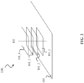
- FIG. 2 shows an antenna device 100 according to an embodiment of the invention, which builds on the embodiment shown in FIG. 1 . Same elements in FIG. 1 and FIG. 2 are labelled with the same reference signs, and may be implemented likewise.
- FIG. 2 illustrates in a three-dimensional (3D) view that the N radiating elements 101 (here four radiating elements 101_1...101_4 are exemplarily shown) may be concentrically arranged on the common axis 102.
- the N radiating elements 101 may in this manner be stacked along the common axis 102, particularly, along the z-axis.
- the N radiating elements 101 may thereby form an end-fire array.
- each radiating element 101 may be arranged in a different plane above (i.e., along the z-axis) the reflector 103.
- the planes may be equidistant and parallel, but also different distances may be applied between the planes.
- Each radiating element 101 may have the same radiating area, as indicated in FIG. 2 . However, typically, a radiating element 101 closer to the reflector 103 may have a larger radiating area than a radiating element 101 further away from the reflector 103 along the common axis 102.
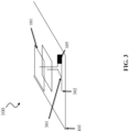
- FIG. 3 shows an antenna device 100 according to an embodiment of the invention, which builds on the embodiments shown in FIG. 1 and FIG. 2 .
- Same elements in FIG. 1 , 2 and 3 , respectively, are labelled with the same reference signs, and may be implemented likewise.
- FIG. 3 shows that the feed structure 104 may comprises a feed line 301 for each radiating element 101 of the array.
- each feed line 301 may have a different length than the other feed lines 301.
- FIG. 3 further shows that the different feed lines 301 may be fed and/or may branch off from a combined port 302 (may be a common feeding point for the array of radiating elements 101, in particular, if each radiating element 101 is fed the same RF signal).
- one phase shifter 105 may be used per feed line 301 to affect the phase of an RF signal provided via that feed line 301.
- one phase shifter 105 may also affect multiple feed lines 301 as shown in FIG. 3 .
- Each feed line 301 may further have a different length than the other feed lines 301, since the feed lines 301 feed radiating elements 101 at different defined distances from the reflector 103 (the feed lines 301 may run from the reflector 103 along the common axis 102 to the respective radiating elements 101).
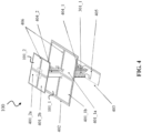
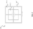
- FIG. 4 , 5 and 6 show an antenna device 100 according to an exemplary embodiment of the invention, which builds on the antenna device 100 of FIG. 1 , 2 or 3 . Same elements shown in the figures are labelled with the same reference signs, and may be implemented likewise.
- FIG. 2 also shows the feed structure 104.
- FIG. 4 , 5 and 6 show two radiating elements 101_1 and 101_2.
- the bottom radiating element 101_1 comprises a bottom dipole
- the top radiating element 101_2 comprises a top dipole (see FIG. 4 ).
- Each radiating element 101 specifically comprises a Printed Circuit Board (PCB) substrate 406 on which the respective dipole is defined.
- the top radiating element 101_2 comprises a top dipole arm 401_2a for a first polarization, and a top dipole arm 401_2b for a second polarization. These polarizations may be orthogonal.
- the top dipole arms 401_2a and 401_2b are defined in the PCB substrate 406 of the top radiating element 101_2.
- the antenna device 100 may also comprise a top dipole balun 404_2 for the top dipole.
- the bottom radiating element 101_2 comprises a bottom dipole arm 401_1a for the first polarization, and a bottom dipole arm 401_1b for the second polarization.
- the bottom dipole arms 401_1a and 401_1b are defined in the PCB substrate 406 of the bottom radiating element 101_1.
- the antenna device 100 may comprise a bottom dipole balun 404_1 for the bottom dipole.
- the bottom radiating element 101_1 may have a larger radiating area than the top radiating element 101_2, and accordingly, may have dipole arms of different lengths (see FIG. 5 ).
- the bottom radiating element 101_1 further comprises a conductive ring 402, in particular, it is surrounded by a conductive ring 402.
- the conductive ring 402 may be used for matching and beam width improvement.
- the top radiating element 101_2 could be surrounded by such a conductive ring 402.
- the antenna device 100 comprises a base PCB substrate 403.
- the reflector 103 may be provided on the base PCB substrate 403, e.g., on the bottom side as metallization.
- the antenna device 100 may further comprise a power splitter 405 to control an amplitude difference between the two radiating elements 101_1 and 101_2.
- the power splitter 405 may be arranged between feed lines 301_1 and 301_2 for the lower radiating element 101_1 and upper radiating element 101_2, respectively.
- a phase shifter 105 (not shown) controls the phase difference ⁇ .
- at least one of the feed lines 301_1 and 301_2 may have a meandering line portion.
- the feed line 301_1 for the lower radiating element 101_1 comprises a meandering line portion (see FIG. 6 ) to additionally add to the phase difference ⁇ .
- the antenna device 100 also comprise a support structure 600 configured to hold each radiating element 101 of the array such that the radiating elements 101 are all arranged on the common axis 102.
- the support structure 600 may be or comprise a PCB, on which the feeding lines 301 are arranged.
- the phase difference ⁇ between the radiating elements 101_1 and 101_2 can be chosen to be 240°.
- the balun 404_2 of the top dipole (of radiating element 101_2) may be rotated (or mirrored) to provide 180° phase offset (see FIG. 6 ), therefore reducing the difference in length required between the feeding lines 301_1 and 301_2 of the top and bottom dipoles (radiating elements 101_1 and 101_2).
- the feed structure 104 may comprise one or more rotated baluns, wherein each of the one or more rotated baluns is associated with one of the radiating elements 101 of the array.
- Each rotated balun may be configured to contribute a phase offset of 180° to the phase difference ⁇ of said one of the radiating elements 101 relative to the RF signal at the first radiating element of the array.
- a phase dispersion with frequency may be reduced, so that the radiation pattern of the antenna device 100 is more stable with frequency and the bandwidth may be effectively increased.
- embodiments of the invention provide a novel approach for increasing the directivity of an array of radiating elements 101 and thus the antenna device 100, without increasing the width of the reflector 103.
- the embodiments of the invention allows tuning the HBW of the antenna device 100 to desired values. Further, the embodiments of the invention allow an improvement of the front to back and cross-polar discrimination when more than two radiating elements 101 are used. The embodiments of the invention further allow a height reduction of the antenna device 100 compared to other antenna architectures.
- a phase difference ⁇ an amplitude difference, and a distance between each of N radiating elements 101 may be are used as degrees of freedom to improve the antenna device 100 performance.
- the assembly of the antenna device 100 is fairly easy and may use standard materials and processes.
- the resulting antenna device 100 may be broadband enough to support current bands in base stations, particularly of 5G base stations.
Landscapes
- Variable-Direction Aerials And Aerial Arrays (AREA)
- Aerials With Secondary Devices (AREA)
Claims (13)
- Antennenvorrichtung (100), umfassend:eine Anordnung aus N Strahlungselementen (101), wobei N eine Ganzzahl größer als eins ist und die N Strahlungselemente (101) auf einer gemeinsamen Achse (102) angeordnet sind und jedes Strahlungselement (101) dazu konfiguriert ist, als Reaktion auf ein dem jeweiligen Strahlungselement (101) zugeführtes Hochfrequenz(HF)-Signal eine Radiowelle auszustrahlen;einen Reflektor (103), der auf der gemeinsamen Achse (102) angeordnet und dazu ausgebildet ist, die N Radiowellen von den N Strahlungselementen (101) in eine Hauptabstrahlrichtung zu reflektieren;eine Zuführstruktur (104), die dazu konfiguriert ist, jedem Strahlungselement (101) ein HF-Signal zuzuführen, wobei das HF-Signal an jedem Strahlungselement (101) eine jeweilige Phasendifferenz (α) relativ zu dem HF-Signal an einem ersten Strahlungselement (101) der Anordnung aufweist, wobei die Zuführstruktur (104) eine Zuführleitung (301) für jedes Strahlungselement (101) der Anordnung und einen oder mehrere Phasenschieber (105) umfasst, die dazu konfiguriert sind, für ein oder mehrere oder alle Strahlungselemente (101) der Anordnung die Phasendifferenz (α) des HF-Signals an dem jeweiligen Strahlungselement (101) einzustellen, wobei jede Zuführleitung (301) eine andere Länge als die anderen Zuführleitungen (301) aufweist, und dadurch gekennzeichnet, dass eine oder mehrere Zuführleitungen (301) jeweils einen mäanderförmigen Leitungsabschnitt umfassen.
- Antennenvorrichtung (100) nach Anspruch 1, wobei die N Strahlungselemente (101) und der Reflektor (103) derart positioniert sind und die Phasenschieber (105) derart konfiguriert sind, dass die von den Strahlungselementen (101) abgestrahlten Radiowellen in der Hauptabstrahlrichtung konstruktiv interferieren.
- Antennenvorrichtung (100) nach Anspruch 1 oder 2, wobei die Hauptabstrahlrichtung die Richtung weg vom Reflektor (103) entlang der gemeinsamen Achse (102) ist.
- Antennenvorrichtung (100) nach einem der Ansprüche 1 bis 3, wobei der eine oder die mehreren Phasenschieber (105) einen oder mehrere steuerbare Phasenschieber umfassen, um die Phasendifferenz (α) des HF-Signals an einem oder mehreren oder allen Strahlungselementen (101) der Anordnung einzustellen.
- Antennenvorrichtung (100) nach einem der Ansprüche 1 bis 4, wobei:jedes Strahlungselement (101) der Anordnung einen Dipol umfasst; unddie Zuführstruktur (104) ferner ein oder mehrere gedrehte Symmetrieglieder umfasst, wobei jedes von dem einen oder den mehreren gedrehten Symmetriegliedern mit einem der Strahlungselemente (101) der Anordnung verknüpft ist und dazu konfiguriert ist, einen Phasenversatz von 180° zur Phasendifferenz (α) des einen der Strahlungselemente (101) relativ zum HF-Signal am ersten Strahlungselement (101) der Anordnung beizutragen.
- Antennenvorrichtung (100) nach einem der Ansprüche 1 bis 5, wobei:
das HF-Signal an einem oder mehreren Strahlungselementen (101) einen jeweiligen Amplitudenunterschied relativ zum HF-Signal am ersten Strahlungselement (101) der Anordnung aufweist. - Antennenvorrichtung (100) nach Anspruch 6, wobei die Zuführstruktur (104) ferner Folgendes umfasst:
einen oder mehrere Leistungsteiler (405) für ein oder mehrere oder alle Strahlungselemente (101) der Anordnung, um die Amplitudendifferenz des HF-Signals am jeweiligen Strahlungselement (101) einzustellen. - Antennenvorrichtung (100) nach einem der Ansprüche 1 bis 7, wobei:
die Zuführstruktur (104) dazu konfiguriert ist, zwei oder mehr Strahlungselemente (101) der Anordnung aus zwei oder mehr unterschiedlichen Quellen oder separat von derselben Quelle zu speisen. - Antennenvorrichtung (100) nach einem der Ansprüche 1 bis 8, wobei:
ein näher am Reflektor (103) befindliches Strahlungselement (101) eine größere Strahlungsfläche auf ein entlang der gemeinsamen Achse (102) weiter vom Reflektor (103) entferntes Strahlungselement (101) aufweist. - Antennenvorrichtung (100) nach einem der Ansprüche 1 bis 9, wobei:
die Anordnung aus den N Strahlungselementen (101) eine Längsstrahlanordnung ist. - Antennenvorrichtung (100) nach einem der Ansprüche 1 bis 10, ferner umfassend:
eine Trägerstruktur (600), die dazu konfiguriert ist, jedes Strahlungselement (101) der Anordnung so zu halten, dass die Strahlungselemente (101) alle auf der gemeinsamen Achse (102) angeordnet sind. - Antennenvorrichtung (100) nach einem der Ansprüche 1 bis 11, wobei:
jedes Strahlungselement (101) einen unterschiedlichen definierten Abstand zum ersten Strahlungselement (101) der Anordnung aufweist. - Antennenvorrichtung (100) nach einem der Ansprüche 1 bis 12, umfassend:eine weitere Anordnung aus M Strahlungselementen, wobei M eine Ganzzahl größer als eins ist und die M Strahlungselemente auf einer anderen gemeinsamen Achse angeordnet sind, wobei jedes Strahlungselement der weiteren Anordnung so konfiguriert ist, dass es als Reaktion auf ein HF-Signal, das dem jeweiligen Strahlungselement der weiteren Anordnung zugeführt wird, eine Radiowelle ausstrahlt; undeine weitere Zuführstruktur, die dazu konfiguriert ist, jedem Strahlungselement der weiteren Anordnung ein HF-Signal zuzuführen, wobei das HF-Signal an jedem Strahlungselement der weiteren Anordnung eine jeweilige Phasendifferenz relativ zu dem HF-Signal an einem ersten Strahlungselement der weiteren Anordnung aufweist, wobei die weitere Zuführstruktur einen oder mehrere Phasenschieber umfasst, die dazu konfiguriert sind, für ein oder mehrere oder alle Strahlungselemente der weiteren Anordnung die Phasendifferenz des HF-Signals an dem jeweiligen Strahlungselement der weiteren Anordnung einzustellen;wobei die Anordnung aus N Strahlungselementen und die weitere Anordnung aus M Strahlungselementen so angeordnet sind, dass sie eine Breitseiten-Anordnung der Antennenvorrichtung bilden.
Applications Claiming Priority (1)
| Application Number | Priority Date | Filing Date | Title |
|---|---|---|---|
| PCT/EP2020/070450 WO2022017576A1 (en) | 2020-07-20 | 2020-07-20 | An antenna device with improved radiation directivity |
Publications (2)
| Publication Number | Publication Date |
|---|---|
| EP4183001A1 EP4183001A1 (de) | 2023-05-24 |
| EP4183001B1 true EP4183001B1 (de) | 2025-01-01 |
Family
ID=71738143
Family Applications (1)
| Application Number | Title | Priority Date | Filing Date |
|---|---|---|---|
| EP20743669.2A Active EP4183001B1 (de) | 2020-07-20 | 2020-07-20 | Antennenvorrichtung mit verbesserter strahlungsrichtcharakteristik |
Country Status (4)
| Country | Link |
|---|---|
| US (1) | US20230163462A1 (de) |
| EP (1) | EP4183001B1 (de) |
| CN (1) | CN115917879B (de) |
| WO (1) | WO2022017576A1 (de) |
Families Citing this family (4)
| Publication number | Priority date | Publication date | Assignee | Title |
|---|---|---|---|---|
| EP4725079A1 (de) * | 2023-08-03 | 2026-04-15 | Huawei Technologies Co., Ltd. | Antennenvorrichtungen, gruppenantennen und antennensysteme |
| EP4725080A1 (de) * | 2023-08-03 | 2026-04-15 | Huawei Technologies Co., Ltd. | Antennenvorrichtung und antennensystem |
| CN117913527B (zh) * | 2024-02-01 | 2024-07-12 | 南通大学 | 一种方向图可重构垂直极化端射天线 |
| WO2025175501A1 (en) * | 2024-02-21 | 2025-08-28 | Huawei Technologies Co., Ltd. | A base station antenna having a reduced number of components and interfaces |
Family Cites Families (9)
| Publication number | Priority date | Publication date | Assignee | Title |
|---|---|---|---|---|
| US6466172B1 (en) * | 2001-10-19 | 2002-10-15 | The United States Of America As Represented By The Secretary Of The Navy | GPS and telemetry antenna for use on projectiles |
| US8484277B2 (en) * | 2007-12-07 | 2013-07-09 | Rambus Inc. | Transforming signals using passive circuits |
| DE102012016627A1 (de) * | 2012-08-22 | 2014-02-27 | Kathrein Werke Kg | Patch-Strahler |
| EP2747195B1 (de) * | 2012-12-21 | 2017-02-08 | Stichting IMEC Nederland | Antennenanordnung für drahtlosen Antrieb |
| US10553962B2 (en) * | 2014-12-09 | 2020-02-04 | Communication Components Antenna Inc. | Dipole antenna with beamforming ring |
| EP3168927B1 (de) * | 2015-11-16 | 2022-02-23 | Huawei Technologies Co., Ltd. | Hochkompakte, ultrabreitbandige duale polarisierte basisstationsantenne |
| CN205282641U (zh) * | 2015-12-23 | 2016-06-01 | 安谱络(苏州)通讯技术有限公司 | 一种新型的天线辐射单元 |
| US10439297B2 (en) * | 2016-06-16 | 2019-10-08 | Sony Corporation | Planar antenna array |
| CN115552729B (zh) * | 2020-05-14 | 2025-02-21 | 华为技术有限公司 | 用于波束宽度控制的复合天线振子的设计与方法 |
-
2020
- 2020-07-20 CN CN202080102769.8A patent/CN115917879B/zh active Active
- 2020-07-20 WO PCT/EP2020/070450 patent/WO2022017576A1/en not_active Ceased
- 2020-07-20 EP EP20743669.2A patent/EP4183001B1/de active Active
-
2023
- 2023-01-20 US US18/157,702 patent/US20230163462A1/en active Pending
Also Published As
| Publication number | Publication date |
|---|---|
| CN115917879B (zh) | 2025-03-07 |
| US20230163462A1 (en) | 2023-05-25 |
| WO2022017576A1 (en) | 2022-01-27 |
| CN115917879A (zh) | 2023-04-04 |
| EP4183001A1 (de) | 2023-05-24 |
Similar Documents
| Publication | Publication Date | Title |
|---|---|---|
| US20230163462A1 (en) | Antenna device with improved radiation directivity | |
| CA3099910C (en) | Dielectric antenna array and system | |
| US20210104813A1 (en) | Base station antennas including supplemental arrays | |
| US10505609B2 (en) | Small cell beam-forming antennas | |
| CN106450690B (zh) | 低剖面覆盖式天线 | |
| US6317092B1 (en) | Artificial dielectric lens antenna | |
| US8184056B1 (en) | Radial constrained lens | |
| US7006053B2 (en) | Adjustable reflector system for fixed dipole antenna | |
| US11418975B2 (en) | Base station antennas with sector splitting in the elevation plan based on frequency band | |
| US20240072420A1 (en) | Beamforming antennas with omnidirectional coverage in the azimuth plane | |
| WO2021226837A1 (zh) | 天线、天线阵列和通信装置 | |
| Miao et al. | Design of dual-mode arc-shaped dipole arrays for indoor base-station applications | |
| KR102601186B1 (ko) | 다중 대역 다중 배열 기지국 안테나 | |
| EP3357125B1 (de) | Gewölbte antenne | |
| Ta et al. | A cavity-backed angled-dipole antenna array for low millimeter-wave bands | |
| EP4725080A1 (de) | Antennenvorrichtung und antennensystem | |
| EP4427299A1 (de) | Antennenvorrichtung mit zwei gestapelten strahlungselementen | |
| US10992044B2 (en) | Antenna system, communication terminal and base station | |
| US5877729A (en) | Wide-beam high gain base station communications antenna | |
| US12355158B1 (en) | Vivaldi antenna structures with concurrent transmit and receive | |
| WO2022063387A1 (en) | Dual polarized semi-continuous dipole antenna device, antenna array and antenna architecture | |
| US12334639B2 (en) | Low-profile wideband antenna with controlled radiation pattern | |
| US12148999B1 (en) | Multimode vivaldi antenna structures | |
| Mustacchio et al. | E Band high gain antenna for 5G Backhauling Systems | |
| WO2025176328A1 (en) | An antenna with a multi-layer radiator compring an interposed mathcing element |
Legal Events
| Date | Code | Title | Description |
|---|---|---|---|
| STAA | Information on the status of an ep patent application or granted ep patent |
Free format text: STATUS: UNKNOWN |
|
| STAA | Information on the status of an ep patent application or granted ep patent |
Free format text: STATUS: THE INTERNATIONAL PUBLICATION HAS BEEN MADE |
|
| PUAI | Public reference made under article 153(3) epc to a published international application that has entered the european phase |
Free format text: ORIGINAL CODE: 0009012 |
|
| STAA | Information on the status of an ep patent application or granted ep patent |
Free format text: STATUS: REQUEST FOR EXAMINATION WAS MADE |
|
| 17P | Request for examination filed |
Effective date: 20230216 |
|
| AK | Designated contracting states |
Kind code of ref document: A1 Designated state(s): AL AT BE BG CH CY CZ DE DK EE ES FI FR GB GR HR HU IE IS IT LI LT LU LV MC MK MT NL NO PL PT RO RS SE SI SK SM TR |
|
| DAV | Request for validation of the european patent (deleted) | ||
| DAX | Request for extension of the european patent (deleted) | ||
| REG | Reference to a national code |
Ref country code: DE Ref legal event code: R079 Ipc: H01Q0019100000 Ref country code: DE Ref legal event code: R079 Ref document number: 602020044055 Country of ref document: DE Free format text: PREVIOUS MAIN CLASS: H01Q0021120000 Ipc: H01Q0019100000 |
|
| GRAP | Despatch of communication of intention to grant a patent |
Free format text: ORIGINAL CODE: EPIDOSNIGR1 |
|
| STAA | Information on the status of an ep patent application or granted ep patent |
Free format text: STATUS: GRANT OF PATENT IS INTENDED |
|
| RIC1 | Information provided on ipc code assigned before grant |
Ipc: H01Q 21/24 20060101ALN20240726BHEP Ipc: H01Q 9/28 20060101ALN20240726BHEP Ipc: H01Q 5/40 20150101ALN20240726BHEP Ipc: H01Q 1/24 20060101ALN20240726BHEP Ipc: H01Q 21/08 20060101ALI20240726BHEP Ipc: H01Q 21/00 20060101ALI20240726BHEP Ipc: H01Q 3/36 20060101ALI20240726BHEP Ipc: H01Q 19/10 20060101AFI20240726BHEP |
|
| INTG | Intention to grant announced |
Effective date: 20240812 |
|
| GRAS | Grant fee paid |
Free format text: ORIGINAL CODE: EPIDOSNIGR3 |
|
| GRAA | (expected) grant |
Free format text: ORIGINAL CODE: 0009210 |
|
| STAA | Information on the status of an ep patent application or granted ep patent |
Free format text: STATUS: THE PATENT HAS BEEN GRANTED |
|
| AK | Designated contracting states |
Kind code of ref document: B1 Designated state(s): AL AT BE BG CH CY CZ DE DK EE ES FI FR GB GR HR HU IE IS IT LI LT LU LV MC MK MT NL NO PL PT RO RS SE SI SK SM TR |
|
| REG | Reference to a national code |
Ref country code: GB Ref legal event code: FG4D |
|
| P01 | Opt-out of the competence of the unified patent court (upc) registered |
Free format text: CASE NUMBER: APP_63565/2024 Effective date: 20241129 |
|
| REG | Reference to a national code |
Ref country code: DE Ref legal event code: R096 Ref document number: 602020044055 Country of ref document: DE |
|
| REG | Reference to a national code |
Ref country code: CH Ref legal event code: EP |
|
| REG | Reference to a national code |
Ref country code: IE Ref legal event code: FG4D |
|
| REG | Reference to a national code |
Ref country code: LT Ref legal event code: MG9D |
|
| REG | Reference to a national code |
Ref country code: NL Ref legal event code: MP Effective date: 20250101 |
|
| REG | Reference to a national code |
Ref country code: AT Ref legal event code: MK05 Ref document number: 1757279 Country of ref document: AT Kind code of ref document: T Effective date: 20250101 |
|
| PG25 | Lapsed in a contracting state [announced via postgrant information from national office to epo] |
Ref country code: NL Free format text: LAPSE BECAUSE OF FAILURE TO SUBMIT A TRANSLATION OF THE DESCRIPTION OR TO PAY THE FEE WITHIN THE PRESCRIBED TIME-LIMIT Effective date: 20250101 |
|
| PG25 | Lapsed in a contracting state [announced via postgrant information from national office to epo] |
Ref country code: FI Free format text: LAPSE BECAUSE OF FAILURE TO SUBMIT A TRANSLATION OF THE DESCRIPTION OR TO PAY THE FEE WITHIN THE PRESCRIBED TIME-LIMIT Effective date: 20250101 |
|
| PG25 | Lapsed in a contracting state [announced via postgrant information from national office to epo] |
Ref country code: PL Free format text: LAPSE BECAUSE OF FAILURE TO SUBMIT A TRANSLATION OF THE DESCRIPTION OR TO PAY THE FEE WITHIN THE PRESCRIBED TIME-LIMIT Effective date: 20250101 |
|
| PG25 | Lapsed in a contracting state [announced via postgrant information from national office to epo] |
Ref country code: ES Free format text: LAPSE BECAUSE OF FAILURE TO SUBMIT A TRANSLATION OF THE DESCRIPTION OR TO PAY THE FEE WITHIN THE PRESCRIBED TIME-LIMIT Effective date: 20250101 |
|
| PG25 | Lapsed in a contracting state [announced via postgrant information from national office to epo] |
Ref country code: NO Free format text: LAPSE BECAUSE OF FAILURE TO SUBMIT A TRANSLATION OF THE DESCRIPTION OR TO PAY THE FEE WITHIN THE PRESCRIBED TIME-LIMIT Effective date: 20250401 Ref country code: IS Free format text: LAPSE BECAUSE OF FAILURE TO SUBMIT A TRANSLATION OF THE DESCRIPTION OR TO PAY THE FEE WITHIN THE PRESCRIBED TIME-LIMIT Effective date: 20250501 |
|
| PG25 | Lapsed in a contracting state [announced via postgrant information from national office to epo] |
Ref country code: HR Free format text: LAPSE BECAUSE OF FAILURE TO SUBMIT A TRANSLATION OF THE DESCRIPTION OR TO PAY THE FEE WITHIN THE PRESCRIBED TIME-LIMIT Effective date: 20250101 |
|
| PG25 | Lapsed in a contracting state [announced via postgrant information from national office to epo] |
Ref country code: LV Free format text: LAPSE BECAUSE OF FAILURE TO SUBMIT A TRANSLATION OF THE DESCRIPTION OR TO PAY THE FEE WITHIN THE PRESCRIBED TIME-LIMIT Effective date: 20250101 Ref country code: PT Free format text: LAPSE BECAUSE OF FAILURE TO SUBMIT A TRANSLATION OF THE DESCRIPTION OR TO PAY THE FEE WITHIN THE PRESCRIBED TIME-LIMIT Effective date: 20250502 |
|
| PGFP | Annual fee paid to national office [announced via postgrant information from national office to epo] |
Ref country code: FR Payment date: 20250610 Year of fee payment: 6 |
|
| PG25 | Lapsed in a contracting state [announced via postgrant information from national office to epo] |
Ref country code: GR Free format text: LAPSE BECAUSE OF FAILURE TO SUBMIT A TRANSLATION OF THE DESCRIPTION OR TO PAY THE FEE WITHIN THE PRESCRIBED TIME-LIMIT Effective date: 20250402 Ref country code: BG Free format text: LAPSE BECAUSE OF FAILURE TO SUBMIT A TRANSLATION OF THE DESCRIPTION OR TO PAY THE FEE WITHIN THE PRESCRIBED TIME-LIMIT Effective date: 20250101 |
|
| PG25 | Lapsed in a contracting state [announced via postgrant information from national office to epo] |
Ref country code: AT Free format text: LAPSE BECAUSE OF FAILURE TO SUBMIT A TRANSLATION OF THE DESCRIPTION OR TO PAY THE FEE WITHIN THE PRESCRIBED TIME-LIMIT Effective date: 20250101 |
|
| PG25 | Lapsed in a contracting state [announced via postgrant information from national office to epo] |
Ref country code: CZ Free format text: LAPSE BECAUSE OF FAILURE TO SUBMIT A TRANSLATION OF THE DESCRIPTION OR TO PAY THE FEE WITHIN THE PRESCRIBED TIME-LIMIT Effective date: 20250101 |
|
| PG25 | Lapsed in a contracting state [announced via postgrant information from national office to epo] |
Ref country code: SE Free format text: LAPSE BECAUSE OF FAILURE TO SUBMIT A TRANSLATION OF THE DESCRIPTION OR TO PAY THE FEE WITHIN THE PRESCRIBED TIME-LIMIT Effective date: 20250101 |
|
| REG | Reference to a national code |
Ref country code: DE Ref legal event code: R097 Ref document number: 602020044055 Country of ref document: DE |
|
| PG25 | Lapsed in a contracting state [announced via postgrant information from national office to epo] |
Ref country code: SM Free format text: LAPSE BECAUSE OF FAILURE TO SUBMIT A TRANSLATION OF THE DESCRIPTION OR TO PAY THE FEE WITHIN THE PRESCRIBED TIME-LIMIT Effective date: 20250101 |
|
| PG25 | Lapsed in a contracting state [announced via postgrant information from national office to epo] |
Ref country code: DK Free format text: LAPSE BECAUSE OF FAILURE TO SUBMIT A TRANSLATION OF THE DESCRIPTION OR TO PAY THE FEE WITHIN THE PRESCRIBED TIME-LIMIT Effective date: 20250101 |
|
| PGFP | Annual fee paid to national office [announced via postgrant information from national office to epo] |
Ref country code: DE Payment date: 20250604 Year of fee payment: 6 |
|
| PG25 | Lapsed in a contracting state [announced via postgrant information from national office to epo] |
Ref country code: IT Free format text: LAPSE BECAUSE OF FAILURE TO SUBMIT A TRANSLATION OF THE DESCRIPTION OR TO PAY THE FEE WITHIN THE PRESCRIBED TIME-LIMIT Effective date: 20250101 |
|
| PG25 | Lapsed in a contracting state [announced via postgrant information from national office to epo] |
Ref country code: EE Free format text: LAPSE BECAUSE OF FAILURE TO SUBMIT A TRANSLATION OF THE DESCRIPTION OR TO PAY THE FEE WITHIN THE PRESCRIBED TIME-LIMIT Effective date: 20250101 |
|
| PG25 | Lapsed in a contracting state [announced via postgrant information from national office to epo] |
Ref country code: RO Free format text: LAPSE BECAUSE OF FAILURE TO SUBMIT A TRANSLATION OF THE DESCRIPTION OR TO PAY THE FEE WITHIN THE PRESCRIBED TIME-LIMIT Effective date: 20250101 |
|
| PG25 | Lapsed in a contracting state [announced via postgrant information from national office to epo] |
Ref country code: SK Free format text: LAPSE BECAUSE OF FAILURE TO SUBMIT A TRANSLATION OF THE DESCRIPTION OR TO PAY THE FEE WITHIN THE PRESCRIBED TIME-LIMIT Effective date: 20250101 |
|
| PLBE | No opposition filed within time limit |
Free format text: ORIGINAL CODE: 0009261 |
|
| STAA | Information on the status of an ep patent application or granted ep patent |
Free format text: STATUS: NO OPPOSITION FILED WITHIN TIME LIMIT |
|
| REG | Reference to a national code |
Ref country code: CH Ref legal event code: L10 Free format text: ST27 STATUS EVENT CODE: U-0-0-L10-L00 (AS PROVIDED BY THE NATIONAL OFFICE) Effective date: 20251112 |
|
| 26N | No opposition filed |
Effective date: 20251002 |
|
| REG | Reference to a national code |
Ref country code: CH Ref legal event code: H13 Free format text: ST27 STATUS EVENT CODE: U-0-0-H10-H13 (AS PROVIDED BY THE NATIONAL OFFICE) Effective date: 20260224 |
|
| PG25 | Lapsed in a contracting state [announced via postgrant information from national office to epo] |
Ref country code: LU Free format text: LAPSE BECAUSE OF NON-PAYMENT OF DUE FEES Effective date: 20250720 |
|
| GBPC | Gb: european patent ceased through non-payment of renewal fee |
Effective date: 20250720 |
|
| REG | Reference to a national code |
Ref country code: BE Ref legal event code: MM Effective date: 20250731 |
|
| PG25 | Lapsed in a contracting state [announced via postgrant information from national office to epo] |
Ref country code: GB Free format text: LAPSE BECAUSE OF NON-PAYMENT OF DUE FEES Effective date: 20250720 |
|
| PG25 | Lapsed in a contracting state [announced via postgrant information from national office to epo] |
Ref country code: BE Free format text: LAPSE BECAUSE OF NON-PAYMENT OF DUE FEES Effective date: 20250731 |