EP4293568A2 - Mikroperle - Google Patents
Mikroperle Download PDFInfo
- Publication number
- EP4293568A2 EP4293568A2 EP23207691.9A EP23207691A EP4293568A2 EP 4293568 A2 EP4293568 A2 EP 4293568A2 EP 23207691 A EP23207691 A EP 23207691A EP 4293568 A2 EP4293568 A2 EP 4293568A2
- Authority
- EP
- European Patent Office
- Prior art keywords
- microbead
- coding
- code
- positions
- patterns
- Prior art date
- Legal status (The legal status is an assumption and is not a legal conclusion. Google has not performed a legal analysis and makes no representation as to the accuracy of the status listed.)
- Granted
Links
Images




Classifications
-
- G—PHYSICS
- G01—MEASURING; TESTING
- G01N—INVESTIGATING OR ANALYSING MATERIALS BY DETERMINING THEIR CHEMICAL OR PHYSICAL PROPERTIES
- G01N33/00—Investigating or analysing materials by specific methods not covered by groups G01N1/00 - G01N31/00
- G01N33/48—Biological material, e.g. blood, urine; Haemocytometers
- G01N33/50—Chemical analysis of biological material, e.g. blood, urine; Testing involving biospecific ligand binding methods; Immunological testing
- G01N33/53—Immunoassay; Biospecific binding assay; Materials therefor
- G01N33/543—Immunoassay; Biospecific binding assay; Materials therefor with an insoluble carrier for immobilising immunochemicals
- G01N33/54313—Immunoassay; Biospecific binding assay; Materials therefor with an insoluble carrier for immobilising immunochemicals the carrier being characterised by its particulate form
-
- G—PHYSICS
- G06—COMPUTING OR CALCULATING; COUNTING
- G06K—GRAPHICAL DATA READING; PRESENTATION OF DATA; RECORD CARRIERS; HANDLING RECORD CARRIERS
- G06K19/00—Record carriers for use with machines and with at least a part designed to carry digital markings
- G06K19/06—Record carriers for use with machines and with at least a part designed to carry digital markings characterised by the kind of the digital marking, e.g. shape, nature, code
- G06K19/06009—Record carriers for use with machines and with at least a part designed to carry digital markings characterised by the kind of the digital marking, e.g. shape, nature, code with optically detectable marking
- G06K19/06046—Constructional details
- G06K19/06084—Constructional details the marking being based on nanoparticles or microbeads
-
- G—PHYSICS
- G06—COMPUTING OR CALCULATING; COUNTING
- G06K—GRAPHICAL DATA READING; PRESENTATION OF DATA; RECORD CARRIERS; HANDLING RECORD CARRIERS
- G06K19/00—Record carriers for use with machines and with at least a part designed to carry digital markings
- G06K19/06—Record carriers for use with machines and with at least a part designed to carry digital markings characterised by the kind of the digital marking, e.g. shape, nature, code
- G06K19/06009—Record carriers for use with machines and with at least a part designed to carry digital markings characterised by the kind of the digital marking, e.g. shape, nature, code with optically detectable marking
- G06K19/06046—Constructional details
- G06K19/06121—Constructional details the marking having been punched or cut out, e.g. a barcode machined in a metal work-piece
-
- G—PHYSICS
- G01—MEASURING; TESTING
- G01N—INVESTIGATING OR ANALYSING MATERIALS BY DETERMINING THEIR CHEMICAL OR PHYSICAL PROPERTIES
- G01N2458/00—Labels used in chemical analysis of biological material
Definitions
- the subject matter relates to biological detection, and more particularly, to a microbead used in the biological detection.
- the multiple assay refers to simultaneous quantifying multiple analytes in a single assay.
- the multiple assay uses multiple capture agents, and each capture agent being specific with a target macromolecule.
- each type of capture agent is attached to a predetermined location of the chip.
- the amounts of multiple targets in a complex sample are determined by detecting signals of the molecules at each location of the same type of capture agent.
- microbeads are suspended in the solution. These microbeads contain identification elements (such as "codes") that can be embedded, printed, or produced by one or more elements of the microbeads.
- Each type of capture agent is fixed to the microbeads with the same code, and the signals emitted from the detected molecules on the microbeads with the specific code reflect the amount of the corresponding targets.
- the current codes of the microbead are produced by marking an opaque substance or fluorescent substance inside the microbead.
- the codes of the microbead can be identified by a distribution of the opaque substance or fluorescent substance. As shown in FIGS. 1A and 1B , the black region represents the opaque substance or fluorescent substance.
- such coding method has following shortcomings. 1) The production cost of the microbead is high, and additional processes and materials are needed to mark the codes. 2) There are several subsequent identification steps, and the identification of such codes needs additional white light image or specific fluorescence image of the microbead. 3) Forming the codes inside the microbead limits the number of codes and the size of the region for biological reaction.
- the present disclosure provides a microbead with a code engraved on outside of the microbead.
- the microbead includes a central region and an edge region surrounding the central region.
- An outer contour of the edge region before and after engraving the code is non-circular.
- the edge region includes a plurality of coding positions, the code of the microbead is engraved on the plurality of coding positions, and each bit of the code corresponds to each of the plurality of coding positions.
- the edge region includes corner regions and side regions, and the corner regions and the side regions are connected to each other in a direction surrounding the central region.
- the corner regions are provided with positioning devices and/or marking positions, and the positioning devices and/or the marking positions are configured to allow a computer identification device to identify a front side and a back side of the microbead, a starting position of the code, and a direction of the code.
- the microbead has a first length in a first dimensional direction and a second length in a second dimensional direction perpendicular to the first dimensional direction.
- the first length is longer than the second length, and the edge region surrounds the central region at least on a plane formed by the first dimensional direction and the second dimensional direction.
- the plurality of coding positions is at least arranged on the plane formed by the first dimensional direction and the second dimensional direction.
- a portion of the corner regions is processed to have a shape different from other portions of the corner regions, and the portion of the corner region as a whole serves as the positioning device.
- a portion of the corner regions defines a through hole penetrating the microbead, and the through hole serves as the positioning device.
- a portion of the corner regions is provided with a positioning protrusion, and the positioning protrusion serves as the positioning device.
- the marking position is an oblique line segment or an arc segment generated by cutting one of the corner regions.
- a center of a circle where the arc segment is located is on the microbead.
- the plurality of coding positions is disposed on the side regions. Or the plurality of coding positions is disposed on the side regions and the corner regions.
- the code is presented by engraving code patterns on the plurality of coding positions, and the code patterns is a combination of one or more patterns.
- the coding patterns are triangular coding patterns, rectangular coding patterns, trapezoidal coding patterns, or any combination thereof.
- the coding pattern of at least one of the plurality of coding positions is used to indicate a front side and a back side of the microbead and a direction of the code.
- the coding pattern of the at least one of the plurality of coding positions has a preset vertex, the preset vertex deviates to or from a preset direction, and the preset direction is the direction of the code on the microbead.
- At least one of the coding patterns has directionality, and the directionality of the coding pattern is used as a constituent factor of the code.
- the coding pattern having the directionality further has a preset vertex.
- the preset vertex deviates from or to one of at least two different preset directions, and the different preset directions which the preset vertex deviates from or to represent another different code.
- microbead of the present disclosure since the shape of the microbead deviates from circular, compared to the circular microbead, a ratio of the overall surface area of the non-circular microbead with respect to the perimeter of the microbead before coding is smaller, and more coding positions can be set on the same consumable region, or the size of the consumable region can be reduced by setting a same number of coding positions. Thus, the utilization rate of microbeads can be improved.
- FIG. 3A and FIG. 3B are diagrammatic views of a microbead 10 before and after coding according to a first embodiment of the present disclosure.
- the microbead 10 is non-circular, which can be rectangular (including square, rectangular), trapezoidal, elliptical, and other regular or irregular shape.
- the microbead 10 is a rectangular microbead, and the code is engraved on the outside of the microbead 10.
- the microbead 10 includes an edge region 11 and a central region 12 surrounded by the edge region 11.
- the edge region 11 includes corner regions 13 and side regions 14 besides the corner region 13.
- the corner regions 13 are where four corners of the rectangle are located.
- One corner region 13a includes a marking position A.
- the remaining three corner regions 13b are used as positioning devices for positioning.
- the marking position A and the three corner regions 13b for positioning enable a computer identification device 900 (shown in FIG. 12 ) to accurately position the microbead 10.
- the side regions 14 are where the long and short sides of the rectangle adjacent to the corner regions 13 are located.
- At least one coding position 141 is disposed on each side region 14. Each coding position 141 is used to engrave a code pattern.
- the marking portion A is an oblique line segment generated by cutting the corner region 13a. Lengths of the long and short sides after cutting the corner region 13 are different. In the embodiment shown in FIG.
- one corner region 13a of 10*10 ⁇ m is cut to form the marking position A.
- An included angle E is formed between the marking position A and a triangular coding pattern on the adjacent coding position 141, which is approximately 72°.
- two adjacent coding positions 141 are set on the first short side next to the mark position A in a clockwise direction.
- Four adjacent coding positions 141 are set on the first long side next to the first short side in the clockwise direction.
- Three coding positions 141 are set on the second short side next to the first long side in the clockwise direction.
- Three coding positions 141 are set on the second long side next to the second short side in the clockwise direction.
- a code with a length of 12-bit can be set on the microbead 10
- multiple coding positions on the same side are closely adjacent to each other.
- each coding position 141 is engraved with a coding pattern, and the coding pattern is a triangle with a vertex facing the inside of the microbead 10.
- the coding pattern may also be a triangle with the vertex facing the outside of the microbead 10.
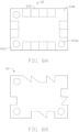
- FIG. 4A and FIG. 4B are diagrammatic views of a microbead 20 before and after coding according to a second embodiment of the present disclosure.
- the microbead 20 in the embodiment is substantially the same as the microbead 10 in the first embodiment, except that the microbead 20 as a whole is more slender than the microbead 10.
- the long side of the rectangular microbead 20 is 35 ⁇ m
- the short side is 20 ⁇ m
- the consumable region is 700 ⁇ m 2 .
- One corner region 23a of 10* 10 ⁇ m is cut to form the marking position A.
- one coding position 241, five coding positions 241, two coding positions 241, and four coding positions 241 are respectively set on the first short side next to the mark position A, the first long side next to the first short side, the second short side next to the first long side, and the second long side next to the second short side.
- the microbead 20 has a larger aspect ratio (that is, the ratio of the long side to the wide side), and the code with a length of 12-bit can still be set although the size of consumable region is reduced.
- FIGS. 5A and 5B are diagrammatic views of a microbead 30 before and after coding according to a third embodiment of the present disclosure.
- the microbead 30 in the embodiment is substantially the same as the microbead 10 in the first embodiment, except that the marking position A is an arc segment generated by cutting one corner region 33a.
- a center of a circle where the arc segment is located is at the microbead 30, and the circle has a radius of 10 ⁇ m.
- the arc segment and the triangular code pattern on the adjacent coding position 341 form an angle of approximately 117°.
- the marking position A of the microbead 30 is more easily recognized by the computer identification device 900.
- the marking position A of the microbead 30 with the arc shape is also more easily recognized by the computer identification device 900. Therefore, the marking position A of the microbead 30 is more easily distinguished by the computer identification device 900 from other corner regions 33b used for positioning, and is more easily recognized by the computer identification device 900.
- FIG. 5B shows one code of the microbead 30. It can be understood that different code combinations are formed by engraving triangular code patterns on different code positions 341, thereby forming different codes.
- FIGS. 6A and 6B are diagrammatic views of a microbead 40 after coding according to a fourth embodiment of the present disclosure.
- the microbeads 40a and 40b in the embodiment are substantially the same as the microbeads 10 of the first embodiment and the microbead 30 of the third embodiment, respectively, except that the size of the marking position A is further reduced in the fourth embodiment. Since the size of the marking position A is reduced, the number of coding positions 441 can be increased, thereby increasing the length of the code.
- the marking position A of the microbead 40a is formed by cutting the corner region 43a of 5*5 ⁇ m, and the radius of the circle where the marking position A of the microbead 40b is located is 5 ⁇ m.
- FIGS. 6A and 6B only show one code of the microbeads 40a and 40b. By engraving the triangular code patterns at different code positions 441, other codes different from those shown in FIGS. 6A and 6B can also be formed.
- the above triangular coding patterns can also be replaced with other types of coding patterns.
- they can be replaced with rectangular patterns, trapezoidal patterns, etc., or a combination thereof.
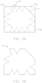
- FIGS. 7A and 7B are diagrammatic views of a microbead before and after coding according to a fifth embodiment of the present disclosure.
- the microbead 50 is a non-circular microbead. Specifically, in the embodiment, the microbead 50 is a rectangular microbead, and the code is engraved on the outside of the microbead 50. Furthermore, the microbead 50 includes an edge region 51 and a central region 52 surrounded by the edge region 51.
- the edge region 51 includes corner regions 53 and side regions 54 besides the corner region 53.
- the corner regions 53 are where the four corners of the rectangle are located.
- the three corner regions 53a are set to have a shape different from that of the other corner region 53b.
- the three corner regions 53a are cut to have an obtuse-angle shape of approximately 125°.
- the other corner region 53b maintains a right-angle shape. It can be understood that setting the three corner regions 53a to be different from the other corner region 53b enables the computer identification device 900 to accurately position the microbead 50, so that the three corner regions 53a constitute the positioning device of the microbead 50.
- the side regions 54 are the regions where the long and short sides of the rectangle adjacent to the corner region 53 are located.
- At least one coding position 541 is provided on each side region 54, and the coding position 541 is used to engrave a code pattern. In the embodiment, the number of the coding positions 541 is 12 in total.
- the code pattern may be a rectangle, a triangle, or a combination thereof.
- FIGS. 8A and 8B are diagrammatic views of a microbead before and after coding according to a sixth embodiment of the present disclosure.
- the microbead 60 in the embodiment is substantially the same as the microbead 50 in the fifth embodiment, except that three corner regions 63a in the embodiment are provided with positioning devices 631a, and the other corner region 63b is not provided with the positioning device.
- the positioning device 631a may be a positioning hole or a positioning protrusion.
- the positioning device 631a may be located at the same position of the front and back sides of the microbead 60. In the embodiment shown in FIG. 8A and FIG.
- the positioning device 631a is a positioning hole penetrating through the front and back sides of the microbead 60, so that the same position of the front and back sides of the microbead 60 can be identified by the computer identification device 900.
- the positioning device 631a may be a positioning protrusion located at a same position or different positions of the front and back sides of the microbead 60.
- the positioning device 631a may also be a positioning protrusion located on one side of the microbead 60 but not on the other side.
- FIG. 9A and FIG. 9B are diagrammatic views of a microbead before and after coding according to a seventh embodiment of the present disclosure.
- the microbead 70 in the embodiment is substantially the same as the microbead 10 in the first embodiment. Difference is that except for the corner region 73a where the marking position A is located, the corner regions 73b of the microbead 70 in the embodiment also set the coding positions 731, thereby increasing the length of the code.
- FIG. 9B shows one code of the microbead 70. It can be understood that by engraving the code patterns on the different code positions 731 and 741, the microbead 70 can obtain more kinds of codes, which improves the utilization rate of the engravable region on the microbead 70.
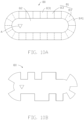
- FIGS. 10A and 10B are diagrammatic views of a microbead before and after coding according to an eighth embodiment of the present disclosure.
- the microbead 80 is a non-circular microbead. Specifically, in the embodiment, the microbead 80 has an oblate shape, and the code is engraved on the outside of the microbeads 80. Furthermore, the microbead 80 includes an edge region 81 and a central region 82 surrounded by the edge region 81. The edge region 81 includes two straight side regions 83 and two arc side regions 84.
- Each of the two arc side regions 84 connects to two ends of the straight side regions 83 extending in the same direction, so that the entire edge region 81 has a surrounding structure surrounding the center region 82.
- a number of coding positions 831 and 841 are set on both the straight side regions 83 and the arc side regions 84.
- a marking position A is set on the central region 82, which deviates from the center of the central region 82.
- the marking position A has a direction indicator, which is convenient for the computer identification device 900 to recognize the front and back sides of the microbead 80 and the starting position of the code according to the position and the direction indicator of the marking position A.
- the marking position A is a triangular through hole or a triangular protrusion.
- the triangular through hole When the triangular through hole is used as the marking position A, the triangular through hole penetrates the front and back surfaces of the microbead 80. When the triangular protrusion is used as the marking position A, the triangular protrusion needs to be set at the same position of the front and back sides of the microbead 80. In the embodiment, the corner of the triangular through hole or the triangular protrusion pointing to the side arc side region 84 can be used as the direction indicator.
- FIG. 10B shows one code of the microbead 80. It can be understood that by engraving the code patterns on the different code positions 831 and 841, the microbead 80 can obtain a variety of different codes. Since the corner region is removed and replaced by the arc side regions 84 connecting to the straight side regions 83, the region of the microbead 80 that can be used to engrave the code is further expanded, so that the microbead 80 can obtain more different codes.
- the edge region of the microbead may also be the arc side regions, the straight side regions, and the corner regions connected in a direction surrounding the central region, and finally forming the entire edge region surrounding the central region.
- the positioning positions may be distributed on the arc side regions and the straight side regions, or on the corner regions at the same time.
- the edge region of the microbead may also be the arc side regions and the corner regions connected in a direction surrounding the central region, and finally forming the entire edge region surrounding the central region.
- the positioning positions may be distributed on the arc side regions or on the corner regions at the same time.
- FIG. 11 is a diagrammatic view of the microbead after coding according to a ninth embodiment of the present disclosure.
- the coding patterns on the microbead 90 also has a direction indicator, so as to prevent the computer identification device 900 to perform an error recognition due to breakage or shield of the marking position, which makes it impossible to recognize or even incorrectly recognize the direction of the code.
- the coding patterns can indicate the direction, the positioning device or the marking position can be omitted.
- the computer identification device 900 can recognize the front and back sides of the microbead 90, the direction of the code, and the starting position of the code based on the direction of the coding pattern, or combined with other factors such as one of the positioning device and the marking position.
- the coding pattern has a preset vertex, which deviates to or deviates from a preset direction.
- the preset direction is preset as the direction of the code.
- the computer identification device 900 recognizes the deviated direction of the preset vertex, thereby recognizing the front and back sides of the microbead 90 and the direction of the code.
- the coding pattern is a triangular coding pattern, and the projection h of the vertex 910 of triangular coding pattern facing the microbead 90 projected on the bottom side opposite to the vertex 910 (shown by the dotted line in the figure) does not fall on the midpoint position i of the bottom side.
- the geometric center X of the coding pattern deviates from the geometric center O of the coding position.
- the triangular coding pattern as a whole presents a slanted state, and the vertex 910 is deviated to one side rather than being disposed at the center.
- the deviated direction of the vertex 910 is preset as the direction of the code of the microbead 90.
- the computer identification device 900 recognizes the deviated direction of the preset vertex 910 of the triangular coding pattern, the front and back sides of the microbead 90, the direction of the code, and the starting position of the code can be recognized according to the marking position A.
- a coding pattern with the direction indicator can be set on a fixed coding position.
- the coding pattern indicates the front and back sides of the microbead, the direction of the code, and the starting position of the code through the direction indicator.
- Other coding patterns are distinguished from the above coding pattern with the direction indicator through the differences of shape, size, orientation, etc.
- the computer identification device 900 can recognize the front and back sides of the microbead, the direction of the code, and the starting position of the code by identifying the coding pattern with the direction indicator.
- the directionality of the coding pattern is also used as a constituent factor of the coding.
- each triangular coding pattern can be set to make the vertex to deviate to the left side or to the right side, thereby obtaining two coding combinations.
- the left deviation and the right deviation here are only used to describe different directions of the vertexes of the triangular coding pattern, and do not have further meaning to limit the present disclosure. Therefore, in different embodiments, the code of the microbead can be obtained by combining one or more constituent factors such as the shape, the size, and the direction of the coding patterns.
- microbeads are set to be rectangular or oblate in the above embodiments, and coding patterns are cut out on the periphery of the rectangular or oblate microbeads to form different codes.
- the shapes of the microbeads can also be elliptical, trapezoidal, irregular, or other shapes deviating from circular.
- the microbead may have a first length in a first dimensional direction and a second length in a second dimensional direction perpendicular to the first dimensional direction. The first length is longer than the second length.
- the microbead further has a central region and an edge region surrounding the central region in the plane formed by the first dimensional direction and the second dimensional direction.
- the edge region is provided with coding positions for engraving the codes. Since the ratio of the first length to the second length increases, the ratio of the overall surface region of the microbead before coding to the perimeter of the microbead before coding can be further reduced, and the utilization rate of the microbead can be further improved.
- FIG. 12 is a diagrammatic view of a computer identification device 900 for identifying the code of the microbead.
- the computer identification device 900 includes an image capturing module 901 and a code identification module 902.
- the image capturing module 901 is used to capture an image of the microbead 1000.
- the code identification module 902 is used to identify the front and back sides of the microbead 1000, the starting position of the code, and the direction of the code based on the marking position of the microbead 1000, the positioning device, the direction indicator of the code patterns, or a combination thereof.
- the code identification module 902 is further used to identify the code of the microbead 1000 according to the coding pattern on each coding position.
- the microbead 1000 can be the microbead in the above embodiment or another microbead that have been appropriately modified but still fall within the scope of the disclosure.
- the image capturing module 901 may be a CMOS camera, a CCD camera, an infrared camera, or the like.
- the code identification module 902 identifies the code of the microbead 1000 according to the code pattern on each coding position. Specifically, when the code on the microbead 1000 has only one code pattern, the code identification module 902 identifies whether the coding position is recessed or not to determine whether the coding position is engraved with the code pattern. When the code on the microbead 1000 has two or more code patterns, the code identification module 902 identifies the preset characteristics of each code pattern.
- the coding identification module 902 first identifies whether one coding position is recessed, and when the coding position is recessed, then further identifies whether the code patten is triangle or rectangle according to a distance from a specific point of the edge of the coding position to another specific point inside the recess.
- the above specific point is predefined and input into the computer identification device 900 as a preset parameter or preset condition.
- the computer identification device 900 may also include a suitable processing unit and a storage unit to complete the microbead code identification function required by the computer identification device 900.
- the processing unit of the computer identification device 900 can execute a software program.
- the storage unit stores the software program executed by the processing unit, and can simultaneously store result data obtained by the processing unit executing the software program, so as to realize the microbead code identification function.
- the code identification module 902 appearing above is a summary and a description of the microbead code identification function realized by the computer identification device 900 executing the software program.
Landscapes
- Health & Medical Sciences (AREA)
- Engineering & Computer Science (AREA)
- Immunology (AREA)
- Life Sciences & Earth Sciences (AREA)
- Chemical & Material Sciences (AREA)
- Molecular Biology (AREA)
- Biomedical Technology (AREA)
- Hematology (AREA)
- Urology & Nephrology (AREA)
- Physics & Mathematics (AREA)
- General Physics & Mathematics (AREA)
- Biotechnology (AREA)
- Pathology (AREA)
- Medicinal Chemistry (AREA)
- Microbiology (AREA)
- Analytical Chemistry (AREA)
- Biochemistry (AREA)
- General Health & Medical Sciences (AREA)
- Cell Biology (AREA)
- Food Science & Technology (AREA)
- Theoretical Computer Science (AREA)
- Nanotechnology (AREA)
- Apparatus Associated With Microorganisms And Enzymes (AREA)
- Editing Of Facsimile Originals (AREA)
- Automatic Analysis And Handling Materials Therefor (AREA)
- Shaping Of Tube Ends By Bending Or Straightening (AREA)
- Micro-Organisms Or Cultivation Processes Thereof (AREA)
- Immobilizing And Processing Of Enzymes And Microorganisms (AREA)
- Seasonings (AREA)
Priority Applications (1)
| Application Number | Priority Date | Filing Date | Title |
|---|---|---|---|
| EP23207691.9A EP4293568B1 (de) | 2019-01-23 | 2019-01-23 | Mikroperle |
Applications Claiming Priority (3)
| Application Number | Priority Date | Filing Date | Title |
|---|---|---|---|
| EP23207691.9A EP4293568B1 (de) | 2019-01-23 | 2019-01-23 | Mikroperle |
| PCT/CN2019/072738 WO2020150910A1 (zh) | 2019-01-23 | 2019-01-23 | 微珠 |
| EP19911678.1A EP3916386B1 (de) | 2019-01-23 | 2019-01-23 | Mikroperle |
Related Parent Applications (2)
| Application Number | Title | Priority Date | Filing Date |
|---|---|---|---|
| EP19911678.1A Division-Into EP3916386B1 (de) | 2019-01-23 | 2019-01-23 | Mikroperle |
| EP19911678.1A Division EP3916386B1 (de) | 2019-01-23 | 2019-01-23 | Mikroperle |
Publications (3)
| Publication Number | Publication Date |
|---|---|
| EP4293568A2 true EP4293568A2 (de) | 2023-12-20 |
| EP4293568A3 EP4293568A3 (de) | 2024-02-28 |
| EP4293568B1 EP4293568B1 (de) | 2025-08-27 |
Family
ID=71735844
Family Applications (2)
| Application Number | Title | Priority Date | Filing Date |
|---|---|---|---|
| EP23207691.9A Active EP4293568B1 (de) | 2019-01-23 | 2019-01-23 | Mikroperle |
| EP19911678.1A Active EP3916386B1 (de) | 2019-01-23 | 2019-01-23 | Mikroperle |
Family Applications After (1)
| Application Number | Title | Priority Date | Filing Date |
|---|---|---|---|
| EP19911678.1A Active EP3916386B1 (de) | 2019-01-23 | 2019-01-23 | Mikroperle |
Country Status (6)
| Country | Link |
|---|---|
| US (1) | US20220091112A1 (de) |
| EP (2) | EP4293568B1 (de) |
| JP (2) | JP7252354B2 (de) |
| CN (1) | CN113287015B (de) |
| ES (1) | ES2974361T3 (de) |
| WO (1) | WO2020150910A1 (de) |
Family Cites Families (16)
| Publication number | Priority date | Publication date | Assignee | Title |
|---|---|---|---|---|
| GB9521943D0 (en) | 1995-10-26 | 1996-01-03 | Univ Hertfordshire | Coded particles for process sequence tracking in combinatorial compound library preparation |
| JPH09320911A (ja) * | 1996-05-27 | 1997-12-12 | Mitsubishi Electric Corp | 被識別機能付き半導体基板 |
| JP2004501344A (ja) | 2000-04-19 | 2004-01-15 | スリー・ディ・モレキュラー・サイエンシィズ・リミテッド | コード化された粒子を製造する方法 |
| AU2003243260A1 (en) * | 2002-05-17 | 2003-12-02 | Nanoventions, Inc. | Microstructured taggant particles, applications and methods of making the same |
| EP1581792A4 (de) | 2002-06-21 | 2008-07-23 | Stephen D Nightingale | Mehrfunktions-produktmarkierungen und verfahren zur herstellung und verwendung dieser |
| GB0318808D0 (en) | 2003-08-11 | 2003-09-10 | Toshiba Res Europ Ltd | An encoded carrier |
| US7858307B2 (en) * | 2005-08-09 | 2010-12-28 | Maxwell Sensors, Inc. | Light transmitted assay beads |
| US20100227770A1 (en) * | 2005-09-13 | 2010-09-09 | Randall True | Brownian microbarcodes for bioassays |
| EP2367633B1 (de) * | 2008-12-23 | 2019-03-27 | MyCartis N.V. | Assayvorrichtung und verfahren zur durchführung biologischer assays |
| EP2237039A1 (de) * | 2009-04-03 | 2010-10-06 | Universitat Autònoma De Barcelona | Codierte Mikropartikel |
| US10436778B2 (en) * | 2013-03-15 | 2019-10-08 | Plexbio Co., Ltd. | Methods and systems for multiplex assays |
| CN103645308B (zh) * | 2013-12-09 | 2015-06-03 | 东南大学 | 一种微载体二维编码方法 |
| US10020264B2 (en) | 2015-04-28 | 2018-07-10 | Infineon Technologies Ag | Integrated circuit substrate and method for manufacturing the same |
| TWI737614B (zh) * | 2015-06-11 | 2021-09-01 | 博錸生技股份有限公司 | 已編碼微載體及其製造方法以及用以進行多工分析之包含該等已編碼微載體之套件 |
| EP3513186A4 (de) * | 2016-09-16 | 2020-04-29 | Plexbio Co., Ltd. | Verfahren und systeme für multiplex-assays |
| US11366109B2 (en) * | 2018-12-06 | 2022-06-21 | Winmems Technologies Co., Ltd. | Encoded microflakes |
-
2019
- 2019-01-23 EP EP23207691.9A patent/EP4293568B1/de active Active
- 2019-01-23 EP EP19911678.1A patent/EP3916386B1/de active Active
- 2019-01-23 WO PCT/CN2019/072738 patent/WO2020150910A1/zh not_active Ceased
- 2019-01-23 ES ES19911678T patent/ES2974361T3/es active Active
- 2019-01-23 CN CN201980088616.XA patent/CN113287015B/zh active Active
- 2019-01-23 JP JP2021542552A patent/JP7252354B2/ja active Active
- 2019-01-23 US US17/423,950 patent/US20220091112A1/en active Pending
-
2023
- 2023-03-23 JP JP2023046697A patent/JP7488931B2/ja active Active
Also Published As
| Publication number | Publication date |
|---|---|
| JP7488931B2 (ja) | 2024-05-22 |
| WO2020150910A1 (zh) | 2020-07-30 |
| EP3916386B1 (de) | 2024-01-31 |
| US20220091112A1 (en) | 2022-03-24 |
| ES2974361T3 (es) | 2024-06-27 |
| CN113287015A (zh) | 2021-08-20 |
| EP4293568B1 (de) | 2025-08-27 |
| JP2022517855A (ja) | 2022-03-10 |
| JP7252354B2 (ja) | 2023-04-04 |
| EP4293568A3 (de) | 2024-02-28 |
| CN113287015B (zh) | 2022-07-08 |
| EP3916386A4 (de) | 2022-09-07 |
| EP3916386A1 (de) | 2021-12-01 |
| JP2023078391A (ja) | 2023-06-06 |
Similar Documents
| Publication | Publication Date | Title |
|---|---|---|
| US10739439B2 (en) | Laser positioning system and position measuring method using the same | |
| US8548221B2 (en) | Microbead automatic recognition method and microbead | |
| JP2005164323A (ja) | 位置検出用マーク、並びに、マーク検出装置、その方法及びそのプログラム | |
| US9292725B2 (en) | Method and system for detecting 2D barcode in a circular label | |
| JP2020144830A (ja) | 作業分析装置及び作業分析プログラム | |
| US4720870A (en) | Method of automatically and electronically analyzing patterns in order to distinguish symmetrical perceptible areas in a scene together with their centers of symmetry | |
| EP3916386B1 (de) | Mikroperle | |
| KR101689980B1 (ko) | 패턴 검사 장치 및 패턴 검사 방법 | |
| CN115994946B (zh) | 平面物体的位姿匹配方法及电子设备 | |
| JPH08210820A (ja) | 部品実装基板の外観検査装置における被検査部の認識方法及び装置 | |
| JP6606471B2 (ja) | 位置検出用ランドマーク及び移動体の位置検出方法 | |
| CN110945530B (zh) | 二维码及二维码读取装置 | |
| HK40051530B (en) | Microbead | |
| HK40051530A (en) | Microbead | |
| JP5280337B2 (ja) | 文字認識方法及び文字認識装置 | |
| CN1319012C (zh) | 部件识别方法和装置 | |
| JPH0713997B2 (ja) | ウエハの要位置合せ角検出装置 | |
| JP2004191338A (ja) | 位置決めマーク検出装置、カット装置および位置決めマーク検出方法 | |
| JP4428392B2 (ja) | マーク位置認識装置およびマーク位置認識方法 | |
| CN116306730B (zh) | 一种具有双激光的条码识读模组与条码识读方法 | |
| JP2001307072A (ja) | 認識システム、認識装置、認識方法および記憶媒体 | |
| KR102476025B1 (ko) | 광학식 전자펜을 위한 그래픽 인디케이터 장치 및 그 이미지 처리 방법 | |
| US20240193972A1 (en) | Text Recognizing Device and Recognizing Method Thereof | |
| JP2531800B2 (ja) | 文字読取装置における文字切り出し方法 | |
| US20240085445A1 (en) | Detection method for sample presence and device associated |
Legal Events
| Date | Code | Title | Description |
|---|---|---|---|
| PUAI | Public reference made under article 153(3) epc to a published international application that has entered the european phase |
Free format text: ORIGINAL CODE: 0009012 |
|
| STAA | Information on the status of an ep patent application or granted ep patent |
Free format text: STATUS: THE APPLICATION HAS BEEN PUBLISHED |
|
| STAA | Information on the status of an ep patent application or granted ep patent |
Free format text: STATUS: REQUEST FOR EXAMINATION WAS MADE |
|
| AC | Divisional application: reference to earlier application |
Ref document number: 3916386 Country of ref document: EP Kind code of ref document: P |
|
| AK | Designated contracting states |
Kind code of ref document: A2 Designated state(s): AL AT BE BG CH CY CZ DE DK EE ES FI FR GB GR HR HU IE IS IT LI LT LU LV MC MK MT NL NO PL PT RO RS SE SI SK SM TR |
|
| 17P | Request for examination filed |
Effective date: 20231128 |
|
| RBV | Designated contracting states (corrected) |
Designated state(s): AL AT BE BG CH CY CZ DE DK EE ES FI FR GB GR HR HU IE IS IT LI LT LU LV MC MK MT NL NO PL PT RO RS SE SI SK SM TR |
|
| REG | Reference to a national code |
Ref country code: DE Ref legal event code: R079 Free format text: PREVIOUS MAIN CLASS: G06K0019060000 Ipc: G01N0033543000 Ref document number: 602019075018 Country of ref document: DE |
|
| PUAL | Search report despatched |
Free format text: ORIGINAL CODE: 0009013 |
|
| AK | Designated contracting states |
Kind code of ref document: A3 Designated state(s): AL AT BE BG CH CY CZ DE DK EE ES FI FR GB GR HR HU IE IS IT LI LT LU LV MC MK MT NL NO PL PT RO RS SE SI SK SM TR |
|
| RIC1 | Information provided on ipc code assigned before grant |
Ipc: G06K 19/06 20060101ALI20240125BHEP Ipc: G01N 33/53 20060101ALI20240125BHEP Ipc: G01N 33/543 20060101AFI20240125BHEP |
|
| GRAP | Despatch of communication of intention to grant a patent |
Free format text: ORIGINAL CODE: EPIDOSNIGR1 |
|
| STAA | Information on the status of an ep patent application or granted ep patent |
Free format text: STATUS: GRANT OF PATENT IS INTENDED |
|
| INTG | Intention to grant announced |
Effective date: 20250415 |
|
| GRAS | Grant fee paid |
Free format text: ORIGINAL CODE: EPIDOSNIGR3 |
|
| GRAA | (expected) grant |
Free format text: ORIGINAL CODE: 0009210 |
|
| STAA | Information on the status of an ep patent application or granted ep patent |
Free format text: STATUS: THE PATENT HAS BEEN GRANTED |
|
| AC | Divisional application: reference to earlier application |
Ref document number: 3916386 Country of ref document: EP Kind code of ref document: P |
|
| AK | Designated contracting states |
Kind code of ref document: B1 Designated state(s): AL AT BE BG CH CY CZ DE DK EE ES FI FR GB GR HR HU IE IS IT LI LT LU LV MC MK MT NL NO PL PT RO RS SE SI SK SM TR |
|
| REG | Reference to a national code |
Ref country code: CH Ref legal event code: EP |
|
| P01 | Opt-out of the competence of the unified patent court (upc) registered |
Free format text: CASE NUMBER: UPC_APP_1330_4293568/2025 Effective date: 20250729 |
|
| REG | Reference to a national code |
Ref country code: DE Ref legal event code: R096 Ref document number: 602019075018 Country of ref document: DE |
|
| REG | Reference to a national code |
Ref country code: IE Ref legal event code: FG4D |
|
| REG | Reference to a national code |
Ref country code: NL Ref legal event code: MP Effective date: 20250827 |
|
| PG25 | Lapsed in a contracting state [announced via postgrant information from national office to epo] |
Ref country code: IS Free format text: LAPSE BECAUSE OF FAILURE TO SUBMIT A TRANSLATION OF THE DESCRIPTION OR TO PAY THE FEE WITHIN THE PRESCRIBED TIME-LIMIT Effective date: 20251227 |
|
| PG25 | Lapsed in a contracting state [announced via postgrant information from national office to epo] |
Ref country code: NO Free format text: LAPSE BECAUSE OF FAILURE TO SUBMIT A TRANSLATION OF THE DESCRIPTION OR TO PAY THE FEE WITHIN THE PRESCRIBED TIME-LIMIT Effective date: 20251127 |
|
| REG | Reference to a national code |
Ref country code: LT Ref legal event code: MG9D |
|
| PG25 | Lapsed in a contracting state [announced via postgrant information from national office to epo] |
Ref country code: PT Free format text: LAPSE BECAUSE OF FAILURE TO SUBMIT A TRANSLATION OF THE DESCRIPTION OR TO PAY THE FEE WITHIN THE PRESCRIBED TIME-LIMIT Effective date: 20251229 |
|
| PG25 | Lapsed in a contracting state [announced via postgrant information from national office to epo] |
Ref country code: FI Free format text: LAPSE BECAUSE OF FAILURE TO SUBMIT A TRANSLATION OF THE DESCRIPTION OR TO PAY THE FEE WITHIN THE PRESCRIBED TIME-LIMIT Effective date: 20250827 |
|
| PG25 | Lapsed in a contracting state [announced via postgrant information from national office to epo] |
Ref country code: HR Free format text: LAPSE BECAUSE OF FAILURE TO SUBMIT A TRANSLATION OF THE DESCRIPTION OR TO PAY THE FEE WITHIN THE PRESCRIBED TIME-LIMIT Effective date: 20250827 Ref country code: NL Free format text: LAPSE BECAUSE OF FAILURE TO SUBMIT A TRANSLATION OF THE DESCRIPTION OR TO PAY THE FEE WITHIN THE PRESCRIBED TIME-LIMIT Effective date: 20250827 |
|
| PG25 | Lapsed in a contracting state [announced via postgrant information from national office to epo] |
Ref country code: GR Free format text: LAPSE BECAUSE OF FAILURE TO SUBMIT A TRANSLATION OF THE DESCRIPTION OR TO PAY THE FEE WITHIN THE PRESCRIBED TIME-LIMIT Effective date: 20251128 |
|
| PG25 | Lapsed in a contracting state [announced via postgrant information from national office to epo] |
Ref country code: SE Free format text: LAPSE BECAUSE OF FAILURE TO SUBMIT A TRANSLATION OF THE DESCRIPTION OR TO PAY THE FEE WITHIN THE PRESCRIBED TIME-LIMIT Effective date: 20250827 |
|
| PG25 | Lapsed in a contracting state [announced via postgrant information from national office to epo] |
Ref country code: LV Free format text: LAPSE BECAUSE OF FAILURE TO SUBMIT A TRANSLATION OF THE DESCRIPTION OR TO PAY THE FEE WITHIN THE PRESCRIBED TIME-LIMIT Effective date: 20250827 |
|
| PG25 | Lapsed in a contracting state [announced via postgrant information from national office to epo] |
Ref country code: PL Free format text: LAPSE BECAUSE OF FAILURE TO SUBMIT A TRANSLATION OF THE DESCRIPTION OR TO PAY THE FEE WITHIN THE PRESCRIBED TIME-LIMIT Effective date: 20250827 Ref country code: BG Free format text: LAPSE BECAUSE OF FAILURE TO SUBMIT A TRANSLATION OF THE DESCRIPTION OR TO PAY THE FEE WITHIN THE PRESCRIBED TIME-LIMIT Effective date: 20250827 |
|
| PG25 | Lapsed in a contracting state [announced via postgrant information from national office to epo] |
Ref country code: RS Free format text: LAPSE BECAUSE OF FAILURE TO SUBMIT A TRANSLATION OF THE DESCRIPTION OR TO PAY THE FEE WITHIN THE PRESCRIBED TIME-LIMIT Effective date: 20251127 |
|
| PG25 | Lapsed in a contracting state [announced via postgrant information from national office to epo] |
Ref country code: ES Free format text: LAPSE BECAUSE OF FAILURE TO SUBMIT A TRANSLATION OF THE DESCRIPTION OR TO PAY THE FEE WITHIN THE PRESCRIBED TIME-LIMIT Effective date: 20250827 |
|
| REG | Reference to a national code |
Ref country code: AT Ref legal event code: MK05 Ref document number: 1830466 Country of ref document: AT Kind code of ref document: T Effective date: 20250827 |
|
| PG25 | Lapsed in a contracting state [announced via postgrant information from national office to epo] |
Ref country code: SM Free format text: LAPSE BECAUSE OF FAILURE TO SUBMIT A TRANSLATION OF THE DESCRIPTION OR TO PAY THE FEE WITHIN THE PRESCRIBED TIME-LIMIT Effective date: 20250827 |
|
| PGFP | Annual fee paid to national office [announced via postgrant information from national office to epo] |
Ref country code: GB Payment date: 20260127 Year of fee payment: 8 |
|
| PG25 | Lapsed in a contracting state [announced via postgrant information from national office to epo] |
Ref country code: DK Free format text: LAPSE BECAUSE OF FAILURE TO SUBMIT A TRANSLATION OF THE DESCRIPTION OR TO PAY THE FEE WITHIN THE PRESCRIBED TIME-LIMIT Effective date: 20250827 |
|
| PGFP | Annual fee paid to national office [announced via postgrant information from national office to epo] |
Ref country code: DE Payment date: 20260114 Year of fee payment: 8 |
|
| PG25 | Lapsed in a contracting state [announced via postgrant information from national office to epo] |
Ref country code: AT Free format text: LAPSE BECAUSE OF FAILURE TO SUBMIT A TRANSLATION OF THE DESCRIPTION OR TO PAY THE FEE WITHIN THE PRESCRIBED TIME-LIMIT Effective date: 20250827 |
|
| PG25 | Lapsed in a contracting state [announced via postgrant information from national office to epo] |
Ref country code: IT Free format text: LAPSE BECAUSE OF FAILURE TO SUBMIT A TRANSLATION OF THE DESCRIPTION OR TO PAY THE FEE WITHIN THE PRESCRIBED TIME-LIMIT Effective date: 20250827 |
|
| PGFP | Annual fee paid to national office [announced via postgrant information from national office to epo] |
Ref country code: FR Payment date: 20260130 Year of fee payment: 8 |
|
| PG25 | Lapsed in a contracting state [announced via postgrant information from national office to epo] |
Ref country code: CZ Free format text: LAPSE BECAUSE OF FAILURE TO SUBMIT A TRANSLATION OF THE DESCRIPTION OR TO PAY THE FEE WITHIN THE PRESCRIBED TIME-LIMIT Effective date: 20250827 |
|
| PG25 | Lapsed in a contracting state [announced via postgrant information from national office to epo] |
Ref country code: SK Free format text: LAPSE BECAUSE OF FAILURE TO SUBMIT A TRANSLATION OF THE DESCRIPTION OR TO PAY THE FEE WITHIN THE PRESCRIBED TIME-LIMIT Effective date: 20250827 Ref country code: EE Free format text: LAPSE BECAUSE OF FAILURE TO SUBMIT A TRANSLATION OF THE DESCRIPTION OR TO PAY THE FEE WITHIN THE PRESCRIBED TIME-LIMIT Effective date: 20250827 |