EP4292717B1 - Installation d'application de produit de revêtement et procédé de commande d'une telle installation - Google Patents
Installation d'application de produit de revêtement et procédé de commande d'une telle installation Download PDFInfo
- Publication number
- EP4292717B1 EP4292717B1 EP23178827.4A EP23178827A EP4292717B1 EP 4292717 B1 EP4292717 B1 EP 4292717B1 EP 23178827 A EP23178827 A EP 23178827A EP 4292717 B1 EP4292717 B1 EP 4292717B1
- Authority
- EP
- European Patent Office
- Prior art keywords
- coating product
- print head
- flow rate
- chamber
- pressure
- Prior art date
- Legal status (The legal status is an assumption and is not a legal conclusion. Google has not performed a legal analysis and makes no representation as to the accuracy of the status listed.)
- Active
Links
Images


Classifications
-
- B—PERFORMING OPERATIONS; TRANSPORTING
- B05—SPRAYING OR ATOMISING IN GENERAL; APPLYING FLUENT MATERIALS TO SURFACES, IN GENERAL
- B05C—APPARATUS FOR APPLYING FLUENT MATERIALS TO SURFACES, IN GENERAL
- B05C11/00—Component parts, details or accessories not specifically provided for in groups B05C1/00 - B05C9/00
- B05C11/10—Storage, supply or control of liquid or other fluent material; Recovery of excess liquid or other fluent material
- B05C11/1002—Means for controlling supply, i.e. flow or pressure, of liquid or other fluent material to the applying apparatus, e.g. valves
- B05C11/1007—Means for controlling supply, i.e. flow or pressure, of liquid or other fluent material to the applying apparatus, e.g. valves responsive to condition of liquid or other fluent material
-
- B—PERFORMING OPERATIONS; TRANSPORTING
- B41—PRINTING; LINING MACHINES; TYPEWRITERS; STAMPS
- B41J—TYPEWRITERS; SELECTIVE PRINTING MECHANISMS, i.e. MECHANISMS PRINTING OTHERWISE THAN FROM A FORME; CORRECTION OF TYPOGRAPHICAL ERRORS
- B41J2/00—Typewriters or selective printing mechanisms characterised by the printing or marking process for which they are designed
- B41J2/005—Typewriters or selective printing mechanisms characterised by the printing or marking process for which they are designed characterised by bringing liquid or particles selectively into contact with a printing material
- B41J2/01—Ink jet
- B41J2/17—Ink jet characterised by ink handling
- B41J2/175—Ink supply systems ; Circuit parts therefor
-
- B—PERFORMING OPERATIONS; TRANSPORTING
- B05—SPRAYING OR ATOMISING IN GENERAL; APPLYING FLUENT MATERIALS TO SURFACES, IN GENERAL
- B05B—SPRAYING APPARATUS; ATOMISING APPARATUS; NOZZLES
- B05B12/00—Arrangements for controlling delivery; Arrangements for controlling the spray area
- B05B12/08—Arrangements for controlling delivery; Arrangements for controlling the spray area responsive to condition of liquid or other fluent material to be discharged, of ambient medium or of target ; responsive to condition of spray devices or of supply means, e.g. pipes, pumps or their drive means
- B05B12/085—Arrangements for controlling delivery; Arrangements for controlling the spray area responsive to condition of liquid or other fluent material to be discharged, of ambient medium or of target ; responsive to condition of spray devices or of supply means, e.g. pipes, pumps or their drive means responsive to flow or pressure of liquid or other fluent material to be discharged
- B05B12/087—Flow or presssure regulators, i.e. non-electric unitary devices comprising a sensing element, e.g. a piston or a membrane, and a controlling element, e.g. a valve
- B05B12/088—Flow or presssure regulators, i.e. non-electric unitary devices comprising a sensing element, e.g. a piston or a membrane, and a controlling element, e.g. a valve the sensing element being a flexible member, e.g. membrane, diaphragm, bellows
-
- B—PERFORMING OPERATIONS; TRANSPORTING
- B05—SPRAYING OR ATOMISING IN GENERAL; APPLYING FLUENT MATERIALS TO SURFACES, IN GENERAL
- B05B—SPRAYING APPARATUS; ATOMISING APPARATUS; NOZZLES
- B05B1/00—Nozzles, spray heads or other outlets, with or without auxiliary devices such as valves, heating means
- B05B1/14—Nozzles, spray heads or other outlets, with or without auxiliary devices such as valves, heating means with multiple outlet openings; with strainers in or outside the outlet opening
-
- B—PERFORMING OPERATIONS; TRANSPORTING
- B05—SPRAYING OR ATOMISING IN GENERAL; APPLYING FLUENT MATERIALS TO SURFACES, IN GENERAL
- B05B—SPRAYING APPARATUS; ATOMISING APPARATUS; NOZZLES
- B05B12/00—Arrangements for controlling delivery; Arrangements for controlling the spray area
- B05B12/004—Arrangements for controlling delivery; Arrangements for controlling the spray area comprising sensors for monitoring the delivery, e.g. by displaying the sensed value or generating an alarm
- B05B12/006—Pressure or flow rate sensors
- B05B12/008—Pressure or flow rate sensors integrated in or attached to a discharge apparatus, e.g. a spray gun
-
- B—PERFORMING OPERATIONS; TRANSPORTING
- B05—SPRAYING OR ATOMISING IN GENERAL; APPLYING FLUENT MATERIALS TO SURFACES, IN GENERAL
- B05B—SPRAYING APPARATUS; ATOMISING APPARATUS; NOZZLES
- B05B12/00—Arrangements for controlling delivery; Arrangements for controlling the spray area
- B05B12/08—Arrangements for controlling delivery; Arrangements for controlling the spray area responsive to condition of liquid or other fluent material to be discharged, of ambient medium or of target ; responsive to condition of spray devices or of supply means, e.g. pipes, pumps or their drive means
- B05B12/085—Arrangements for controlling delivery; Arrangements for controlling the spray area responsive to condition of liquid or other fluent material to be discharged, of ambient medium or of target ; responsive to condition of spray devices or of supply means, e.g. pipes, pumps or their drive means responsive to flow or pressure of liquid or other fluent material to be discharged
- B05B12/087—Flow or presssure regulators, i.e. non-electric unitary devices comprising a sensing element, e.g. a piston or a membrane, and a controlling element, e.g. a valve
-
- B—PERFORMING OPERATIONS; TRANSPORTING
- B05—SPRAYING OR ATOMISING IN GENERAL; APPLYING FLUENT MATERIALS TO SURFACES, IN GENERAL
- B05B—SPRAYING APPARATUS; ATOMISING APPARATUS; NOZZLES
- B05B12/00—Arrangements for controlling delivery; Arrangements for controlling the spray area
- B05B12/08—Arrangements for controlling delivery; Arrangements for controlling the spray area responsive to condition of liquid or other fluent material to be discharged, of ambient medium or of target ; responsive to condition of spray devices or of supply means, e.g. pipes, pumps or their drive means
- B05B12/12—Arrangements for controlling delivery; Arrangements for controlling the spray area responsive to condition of liquid or other fluent material to be discharged, of ambient medium or of target ; responsive to condition of spray devices or of supply means, e.g. pipes, pumps or their drive means responsive to conditions of ambient medium or target, e.g. humidity, temperature position or movement of the target relative to the spray apparatus
-
- B—PERFORMING OPERATIONS; TRANSPORTING
- B05—SPRAYING OR ATOMISING IN GENERAL; APPLYING FLUENT MATERIALS TO SURFACES, IN GENERAL
- B05B—SPRAYING APPARATUS; ATOMISING APPARATUS; NOZZLES
- B05B13/00—Machines or plants for applying liquids or other fluent materials to surfaces of objects or other work by spraying, not covered by groups B05B1/00 - B05B11/00
- B05B13/002—Machines or plants for applying coating liquids or other fluent materials by inkjet
-
- B—PERFORMING OPERATIONS; TRANSPORTING
- B05—SPRAYING OR ATOMISING IN GENERAL; APPLYING FLUENT MATERIALS TO SURFACES, IN GENERAL
- B05B—SPRAYING APPARATUS; ATOMISING APPARATUS; NOZZLES
- B05B13/00—Machines or plants for applying liquids or other fluent materials to surfaces of objects or other work by spraying, not covered by groups B05B1/00 - B05B11/00
- B05B13/02—Means for supporting work; Arrangement or mounting of spray heads; Adaptation or arrangement of means for feeding work
- B05B13/04—Means for supporting work; Arrangement or mounting of spray heads; Adaptation or arrangement of means for feeding work the spray heads being moved during spraying operation
-
- B—PERFORMING OPERATIONS; TRANSPORTING
- B05—SPRAYING OR ATOMISING IN GENERAL; APPLYING FLUENT MATERIALS TO SURFACES, IN GENERAL
- B05C—APPARATUS FOR APPLYING FLUENT MATERIALS TO SURFACES, IN GENERAL
- B05C5/00—Apparatus in which liquid or other fluent material is projected, poured or allowed to flow on to the surface of the work
- B05C5/02—Apparatus in which liquid or other fluent material is projected, poured or allowed to flow on to the surface of the work the liquid or other fluent material being discharged through an outlet orifice by pressure, e.g. from an outlet device in contact or almost in contact, with the work
- B05C5/027—Coating heads with several outlets, e.g. aligned transversally to the moving direction of a web to be coated
- B05C5/0275—Coating heads with several outlets, e.g. aligned transversally to the moving direction of a web to be coated flow controlled, e.g. by a valve
- B05C5/0279—Coating heads with several outlets, e.g. aligned transversally to the moving direction of a web to be coated flow controlled, e.g. by a valve independently, e.g. individually, flow controlled
-
- B—PERFORMING OPERATIONS; TRANSPORTING
- B41—PRINTING; LINING MACHINES; TYPEWRITERS; STAMPS
- B41J—TYPEWRITERS; SELECTIVE PRINTING MECHANISMS, i.e. MECHANISMS PRINTING OTHERWISE THAN FROM A FORME; CORRECTION OF TYPOGRAPHICAL ERRORS
- B41J2/00—Typewriters or selective printing mechanisms characterised by the printing or marking process for which they are designed
- B41J2/005—Typewriters or selective printing mechanisms characterised by the printing or marking process for which they are designed characterised by bringing liquid or particles selectively into contact with a printing material
- B41J2/01—Ink jet
- B41J2/17—Ink jet characterised by ink handling
- B41J2/175—Ink supply systems ; Circuit parts therefor
- B41J2/17503—Ink cartridges
- B41J2/17556—Means for regulating the pressure in the cartridge
-
- B—PERFORMING OPERATIONS; TRANSPORTING
- B41—PRINTING; LINING MACHINES; TYPEWRITERS; STAMPS
- B41J—TYPEWRITERS; SELECTIVE PRINTING MECHANISMS, i.e. MECHANISMS PRINTING OTHERWISE THAN FROM A FORME; CORRECTION OF TYPOGRAPHICAL ERRORS
- B41J2/00—Typewriters or selective printing mechanisms characterised by the printing or marking process for which they are designed
- B41J2/005—Typewriters or selective printing mechanisms characterised by the printing or marking process for which they are designed characterised by bringing liquid or particles selectively into contact with a printing material
- B41J2/01—Ink jet
- B41J2/17—Ink jet characterised by ink handling
- B41J2/175—Ink supply systems ; Circuit parts therefor
- B41J2/17566—Ink level or ink residue control
-
- B—PERFORMING OPERATIONS; TRANSPORTING
- B41—PRINTING; LINING MACHINES; TYPEWRITERS; STAMPS
- B41J—TYPEWRITERS; SELECTIVE PRINTING MECHANISMS, i.e. MECHANISMS PRINTING OTHERWISE THAN FROM A FORME; CORRECTION OF TYPOGRAPHICAL ERRORS
- B41J2/00—Typewriters or selective printing mechanisms characterised by the printing or marking process for which they are designed
- B41J2/005—Typewriters or selective printing mechanisms characterised by the printing or marking process for which they are designed characterised by bringing liquid or particles selectively into contact with a printing material
- B41J2/01—Ink jet
- B41J2/17—Ink jet characterised by ink handling
- B41J2/175—Ink supply systems ; Circuit parts therefor
- B41J2/17596—Ink pumps, ink valves
-
- B—PERFORMING OPERATIONS; TRANSPORTING
- B41—PRINTING; LINING MACHINES; TYPEWRITERS; STAMPS
- B41J—TYPEWRITERS; SELECTIVE PRINTING MECHANISMS, i.e. MECHANISMS PRINTING OTHERWISE THAN FROM A FORME; CORRECTION OF TYPOGRAPHICAL ERRORS
- B41J3/00—Typewriters or selective printing or marking mechanisms characterised by the purpose for which they are constructed
- B41J3/407—Typewriters or selective printing or marking mechanisms characterised by the purpose for which they are constructed for marking on special material
-
- B—PERFORMING OPERATIONS; TRANSPORTING
- B05—SPRAYING OR ATOMISING IN GENERAL; APPLYING FLUENT MATERIALS TO SURFACES, IN GENERAL
- B05B—SPRAYING APPARATUS; ATOMISING APPARATUS; NOZZLES
- B05B1/00—Nozzles, spray heads or other outlets, with or without auxiliary devices such as valves, heating means
- B05B1/30—Nozzles, spray heads or other outlets, with or without auxiliary devices such as valves, heating means designed to control volume of flow, e.g. with adjustable passages
- B05B1/3033—Nozzles, spray heads or other outlets, with or without auxiliary devices such as valves, heating means designed to control volume of flow, e.g. with adjustable passages the control being effected by relative coaxial longitudinal movement of the controlling element and the spray head
- B05B1/304—Nozzles, spray heads or other outlets, with or without auxiliary devices such as valves, heating means designed to control volume of flow, e.g. with adjustable passages the control being effected by relative coaxial longitudinal movement of the controlling element and the spray head the controlling element being a lift valve
- B05B1/3046—Nozzles, spray heads or other outlets, with or without auxiliary devices such as valves, heating means designed to control volume of flow, e.g. with adjustable passages the control being effected by relative coaxial longitudinal movement of the controlling element and the spray head the controlling element being a lift valve the valve element, e.g. a needle, co-operating with a valve seat located downstream of the valve element and its actuating means, generally in the proximity of the outlet orifice
- B05B1/306—Nozzles, spray heads or other outlets, with or without auxiliary devices such as valves, heating means designed to control volume of flow, e.g. with adjustable passages the control being effected by relative coaxial longitudinal movement of the controlling element and the spray head the controlling element being a lift valve the valve element, e.g. a needle, co-operating with a valve seat located downstream of the valve element and its actuating means, generally in the proximity of the outlet orifice the actuating means being a fluid
-
- B—PERFORMING OPERATIONS; TRANSPORTING
- B05—SPRAYING OR ATOMISING IN GENERAL; APPLYING FLUENT MATERIALS TO SURFACES, IN GENERAL
- B05B—SPRAYING APPARATUS; ATOMISING APPARATUS; NOZZLES
- B05B13/00—Machines or plants for applying liquids or other fluent materials to surfaces of objects or other work by spraying, not covered by groups B05B1/00 - B05B11/00
- B05B13/02—Means for supporting work; Arrangement or mounting of spray heads; Adaptation or arrangement of means for feeding work
- B05B13/04—Means for supporting work; Arrangement or mounting of spray heads; Adaptation or arrangement of means for feeding work the spray heads being moved during spraying operation
- B05B13/0431—Means for supporting work; Arrangement or mounting of spray heads; Adaptation or arrangement of means for feeding work the spray heads being moved during spraying operation with spray heads moved by robots or articulated arms, e.g. for applying liquid or other fluent material to three-dimensional [3D] surfaces
- B05B13/0433—Means for supporting work; Arrangement or mounting of spray heads; Adaptation or arrangement of means for feeding work the spray heads being moved during spraying operation with spray heads moved by robots or articulated arms, e.g. for applying liquid or other fluent material to three-dimensional [3D] surfaces the work being vehicle components, e.g. vehicle bodies
-
- B—PERFORMING OPERATIONS; TRANSPORTING
- B05—SPRAYING OR ATOMISING IN GENERAL; APPLYING FLUENT MATERIALS TO SURFACES, IN GENERAL
- B05B—SPRAYING APPARATUS; ATOMISING APPARATUS; NOZZLES
- B05B15/00—Details of spraying plant or spraying apparatus not otherwise provided for; Accessories
- B05B15/40—Filters located upstream of the spraying outlets
-
- B—PERFORMING OPERATIONS; TRANSPORTING
- B05—SPRAYING OR ATOMISING IN GENERAL; APPLYING FLUENT MATERIALS TO SURFACES, IN GENERAL
- B05B—SPRAYING APPARATUS; ATOMISING APPARATUS; NOZZLES
- B05B15/00—Details of spraying plant or spraying apparatus not otherwise provided for; Accessories
- B05B15/50—Arrangements for cleaning; Arrangements for preventing deposits, drying-out or blockage; Arrangements for detecting improper discharge caused by the presence of foreign matter
- B05B15/55—Arrangements for cleaning; Arrangements for preventing deposits, drying-out or blockage; Arrangements for detecting improper discharge caused by the presence of foreign matter using cleaning fluids
-
- B—PERFORMING OPERATIONS; TRANSPORTING
- B05—SPRAYING OR ATOMISING IN GENERAL; APPLYING FLUENT MATERIALS TO SURFACES, IN GENERAL
- B05B—SPRAYING APPARATUS; ATOMISING APPARATUS; NOZZLES
- B05B9/00—Spraying apparatus for discharge of liquids or other fluent material, without essentially mixing with gas or vapour
- B05B9/03—Spraying apparatus for discharge of liquids or other fluent material, without essentially mixing with gas or vapour characterised by means for supplying liquid or other fluent material
- B05B9/04—Spraying apparatus for discharge of liquids or other fluent material, without essentially mixing with gas or vapour characterised by means for supplying liquid or other fluent material with pressurised or compressible container; with pump
- B05B9/0403—Spraying apparatus for discharge of liquids or other fluent material, without essentially mixing with gas or vapour characterised by means for supplying liquid or other fluent material with pressurised or compressible container; with pump with pumps for liquids or other fluent material
- B05B9/0413—Spraying apparatus for discharge of liquids or other fluent material, without essentially mixing with gas or vapour characterised by means for supplying liquid or other fluent material with pressurised or compressible container; with pump with pumps for liquids or other fluent material with reciprocating pumps, e.g. membrane pump, piston pump, bellow pump
-
- B—PERFORMING OPERATIONS; TRANSPORTING
- B41—PRINTING; LINING MACHINES; TYPEWRITERS; STAMPS
- B41J—TYPEWRITERS; SELECTIVE PRINTING MECHANISMS, i.e. MECHANISMS PRINTING OTHERWISE THAN FROM A FORME; CORRECTION OF TYPOGRAPHICAL ERRORS
- B41J2/00—Typewriters or selective printing mechanisms characterised by the printing or marking process for which they are designed
- B41J2/005—Typewriters or selective printing mechanisms characterised by the printing or marking process for which they are designed characterised by bringing liquid or particles selectively into contact with a printing material
- B41J2/01—Ink jet
- B41J2/17—Ink jet characterised by ink handling
- B41J2/175—Ink supply systems ; Circuit parts therefor
- B41J2/17566—Ink level or ink residue control
- B41J2002/17586—Ink level or ink residue control using ink bag deformation for ink level indication
Definitions
- the present invention relates to a coating product application installation which comprises a print head equipped with several nozzles and supplied by a source of coating product.
- each nozzle defines a coating product discharge orifice with a small diameter, of the order of 100 to 300 micrometers ( ⁇ m).
- Each nozzle is controlled by a valve, itself supplied by the coating product source.
- the operation of a print head requires high precision in controlling the pressure of the coating product supplied to the print head. This is all the more true when the product is viscous, for example with a dynamic viscosity between 50 and 300 milliPascal.seconds (mPa.s).
- the potentially viscous coating product In a coating product application installation with a print head, the potentially viscous coating product must be supplied to the various nozzles with a given supply pressure, for example, equal to 2 bar.
- a given supply pressure for example, equal to 2 bar.
- this pressure is greater than 2.1 bar, there is a risk of creating a parasitic paint cloud, called "overspray".
- the supply pressure is less than 1.9 bar, the instantaneous flow rate of coating product in one or more nozzles may not allow the formation of a continuous or quasi-continuous stream at the nozzle outlet. This is why the precision sought in the coating product supply pressure, at the inlet of a print head, is of the order of 100 millibars (mbar). However, this supply pressure depends on the instantaneous flow rate of coating product in the print head.
- the instantaneous flow of coating material through the various nozzle orifices of the print head results from the opening/closing of the valves that control these various nozzles and which have a response time of the order of 1 millisecond (ms).
- a source of coating material is used to supply a print head.
- This source of coating material can be a pressurized coating material tank or a piston tank controlled by an electric motor or other equipment. In all cases, the response time of such equipment is of the order of 500 ms.
- the supply of a print head with coating product, from a source of coating product takes place through a pipe which can have a length of several meters, for example if the print head is arranged at the end of the arm of a multi-axis robot, while the print source is arranged at the foot of this robot.
- This pipe induces regular pressure losses, due to its length and its diameter, as well as singular pressure losses, due to the valves, filters and/or elbows arranged along the length of this pipe.
- the inlet pressure of a print head is relatively difficult to manage based solely on means of controlling the coating product source.
- a known solution in the field of ink application consists of continuously circulating a relatively high flow rate of coating product and taking a flow rate of the order of 10% of this relatively high flow rate to supply nozzles of a print head. This induces a continuous circulation of the ink which is not transposable to the application of a paint-type coating product because the shearing due to the repeated circulation of the coating product would risk damaging the paint.
- a significant flow rate of coating product would have to be brought to the print head, for example equal to 2 liters per minute (l/min) so that 10% of this flow rate represents approximately 200 ml/min. Bringing 2 l/min of coating product to the end of a robot arm turns out to be, in practice, very complicated.
- EP-A-2574471 discloses an ink application system in which a print head is supplied from a reservoir, through a pump and a sub-reservoir equipped with a flexible wall. The operation of the pump is adjusted according to a pressure in a passage provided between the sub-reservoir and the head printing, which does not take into account the ink flow actually ejected by the print head.
- the invention more particularly seeks to remedy by proposing a new coating product application installation in which a coating product supply pressure to a print head can be precisely controlled, taking into account the respective response times of the print head valves and the control members of a coating product source.
- the invention relates to a coating product application installation comprising a print head equipped with several nozzles and supplied by a source of coating product, each nozzle being controlled by a valve supplied by the source of coating product.
- the installation comprises a coating product accumulator installed on a coating product circulation circuit, which passes through the print head, this accumulator comprising a deformable or movable wall delimiting at least in part a first chamber of variable volume supplied with coating product and a second chamber of variable volume supplied with gas under a predetermined pressure.
- the predetermined supply pressure of the second variable volume chamber is equal to a nominal operating pressure of the print head.
- the first variable volume chamber is supplied or purged with coating product due to a difference between an instantaneous flow rate of ejection of coating product by the print head and a supply flow rate of the print head from the source of coating product.
- the installation comprises means for detecting a difference between the instantaneous ejection flow rate and the feed flow rate.
- the installation further comprises a control unit configured to adjust an operating setpoint value of the coating product source as a function of the difference between the instantaneous ejection flow rate and the feed flow rate, in a direction of reducing this difference between the flow rates.
- the accumulator can be sized so that the deformation or movement of its wall makes it possible to store a volume of coating product sufficient to compensate for a variation in pressure of the coating product at the inlet of the print head, during the response time of the source of coating product.
- the invention also makes it possible to take into account possible variations in pressure losses in a supply line connecting the source of coating product to the print head. Since the second chamber of variable volume is supplied with a pressure equal to the nominal operating pressure of the print head and taking into account the deformable or mobile nature of the wall, it is possible to the assumption that the pressure in the first variable volume chamber is equal to the nominal operating pressure of the print head.
- control unit can control the coating product source according to the difference between the instantaneous ejection flow rate and the supply flow rate in an optimized manner, by reducing this difference, which automatically adapts the coating product flow rate delivered by the source to the flow rate actually ejected by the print head.
- the operating setpoint is a control pressure of a pressure tank, a displacement speed of a piston of a piston tank or a rotation speed of a volumetric pump.
- thick continuous lines are used to represent coating product circulation lines
- thick dotted lines are used to represent solvent or cleaning product circulation lines
- thin continuous lines are used to represent air circulation lines
- thick center lines are used to represent electrical conductors for electrical signal circulation.
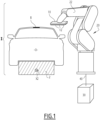
- Installation I represented at figures 1 And 2 is intended for the application of paint to objects O which, in the example of the figures, are motor vehicle bodies. More specifically, in this example, the installation I aims to enable the creation of a strip B of contrasting color, for example black, on the roof of a body.
- the objects to be coated may be parts of a motor vehicle body, for example bumpers or, more generally, any object that can be coated, for example a part of an aircraft fuselage or a household appliance body, these examples not being limiting.
- the coating product applied with the installation I of the invention does not necessarily constitute a contrasting color band.
- This coating product can be a paint, a primer or a varnish or a water-soluble or solvent-based base, a two-component coating.
- its dynamic viscosity can be between 50 and 300 mPa.s.
- the installation I comprises a conveyor 2 intended to move the objects O along a conveying axis X2 perpendicular to the plane of the figure 1 .
- the installation I also comprises a print head 10 mounted at the end of the arm 22 of a multi-axis robot 20 arranged in the vicinity of the conveyor 2.
- the print head 10 is supplied with coating product to be applied from a supply module 30 which comprises a source of coating product to be applied formed here by a pressure tank 32.
- the module 30 is connected to the print head 10 by a supply line 40 which circulates inside the multi-axis robot 20, in particular inside its arm 22.
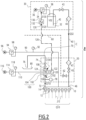
- the module 30 comprises a piloted solenoid valve 34 connected, on the upstream side, to a source of pressurized air which delivers air with a pressure equal to 6 bars.
- the solenoid valve 34 On the downstream side, the solenoid valve 34 is connected to the internal volume V32 of the pressure tank 32.
- a pressure gauge 38 makes it possible to know the pressure of the air delivered by the solenoid valve 34.
- An upstream end 42 of the supply line 40 plunges into the pressure tank.
- a first cut-off valve 43 and a first filter 44 are arranged on the line 40, in its upstream part, inside the supply module 30.
- a downstream end of the supply line 40 is connected to the print head 10 which is therefore supplied with coating product from the source of coating product, through the line 40.
- the pressure of the coating product at the inlet of the print head depends on the pressure of the coating product supplied by the pressure tank and the pressure losses in the supply line, which can vary depending on the position of the arm 22.
- a control module 50 is arranged in proximity to the print head 10, for example in the arm 22 of the multi-axis robot 20.
- proximity to it is meant that the supply module is located less than one meter, preferably less than 50 cm, more preferably less than 20 cm, from the print head.
- the supply line 40 passes through the control module 50.
- the line 40 is equipped with a second cut-off valve 45 and a second filter 47.
- the first filter 44 may be configured to retain elements whose maximum dimension is greater than 40 ⁇ m, while the second filter 47 is configured to retain elements whose maximum dimension is greater than 20 ⁇ m.
- a second pipe 60 for supplying the print head 10 with solvent or cleaning product, is connected to the pipe 40, downstream of the second cut-off valve 45.
- This pipe 60 is itself equipped with a third cut-off valve 62 and connected to a solvent source (not shown), which may be a reservoir or a closed-loop circulation circuit, sometimes called “circulating”.
- the print head 10 is equipped with several nozzles 12, each of which is configured to deliver a jet J12 of coating product to be applied to an object O.
- Each nozzle 12 defines a coating product discharge orifice, not shown, whose diameter is of the order of 100 to 300 ⁇ m.
- Each nozzle 12 is controlled by a valve 14 which is itself supplied with coating product by the pipe 40.
- the valves 14 may be of the type known from EP-A-2442983 or of US-B-9638350 whose technical education is incorporated into this application, by reference.
- valves 14 are controlled electrically or pneumatically, in a manner known per se.
- a third evacuation pipe 70 connects the print head 10 to a purge 80.
- the upstream end 72 of the pipe 70 is connected to the print head 10, while its downstream end 76 opens onto the purge 80.
- a fourth cut-off valve 74 is mounted on the pipe 70.
- a fourth pipe 90 connects a source 96 of pressurized air to the print head 10 while being controlled by a solenoid valve 94 equipped with a pressure gauge 98.
- a pressure sensor 92 is arranged on the pipe 90 and makes it possible to control the pressure supplying the print head 10 with pressurized air, with a predetermined pressure, for example equal to 2 bars. This pressurized air makes it possible to supply the nozzle opening actuators.
- An accumulator 100 is arranged on the line 70, that is to say downstream of the print head 10 in the direction of circulation of the coating product between the coating product source 32 and the purge 80.
- the accumulator 100 is therefore installed on the circuit C.
- This accumulator 100 comprises a deformable wall 102 and a rigid casing 104 which surrounds the deformable wall.
- the deformable wall 102 defines an internal chamber C102 supplied with coating product exiting the print head 10. Given the deformable nature of the wall 102, the internal chamber C102 is of variable volume.
- the flow rate Q'10 can be positive or negative. If the flow rate Q10 is strictly less than the flow rate Q32, the flow rate Q'10 is positive and the variable volume chamber C102 is progressively supplied with coating product. If the flow rate Q10 is strictly greater than the flow rate Q32, the flow rate Q'10 is negative and the variable volume chamber C102 is gradually purged of the coating product it contains.
- a peripheral chamber C104 is defined around the deformable wall 102, inside the rigid envelope 104. Given the deformable nature of the wall 102, the peripheral chamber C104 is also of variable volume.
- deformable it is meant that the wall 102 is elastically deformable, under the effect of a difference in fluid pressure between the variable volume chambers C102 and C104, under normal conditions of use of the installation I, in particular in terms of temperature and pressure of the coating product.
- the deformable wall 102 is sleeve-shaped and extends between a first orifice 106 for inlet of the coating product coming from the print head 10 into the internal chamber C102, i.e. into the accumulator 100, and a second orifice 108 for evacuation of the coating product from the accumulator 100, in the direction of the purge 80.
- a pressure sensor 78 makes it possible to detect the pressure of the coating product in the portion of the pipe 70 connecting the print head 10 and the accumulator 100.
- the peripheral chamber C104 is supplied with pressurized air through a fifth pipe 110 equipped with a piloted solenoid valve 114, the upstream side of which is connected to a source 116 of pressurized air and which is associated with a pressure gauge 118.
- P104 denotes the pressure supplying the chamber C104 with pressurized air, which is determined by the elements 110 to 118.
- the supply pressure P104 is equal to the nominal operating pressure of the print head 10, namely the pressure that the coating product must have at the inlet of the print head.
- the supply pressure P104 of the peripheral chamber C104 with air is equal to the nominal pressure supplying the valves 14 with coating product.
- the peripheral chamber C104 comprises an outlet opening putting the peripheral chamber C104 into fluid communication with an exhaust, or directly with the environment of the print head, so as to establish a permanent flow of air in the chamber C104 between the pipe 110 and this outlet opening.
- This makes it possible to ensure in the external chamber C104 a pressure at a constant value P104, even during variations in the volume of the internal chamber C102.
- This makes it possible to overcome the constraints of regulating the pressure supply to the external chamber C104, which would cause the accumulator 100 to lose response time and performance. Thanks to this permanent circulation at a set pressure, the pressure in the chamber C104 device is constant without response time, and the nozzle pressure regulation performance is greatly improved.
- a sensor 120 is connected to the accumulator 100 and configured to detect a deformation of the deformable wall 102.
- a deformation of the wall 102 corresponds to a situation where the flow rates Q10 and Q32 are different.
- the sensor 120 is a means of detecting a difference between these flow rates.
- the senor 120 may be an inductive sensor that includes an inductive cell 122 capable of detecting the position of a metal element 124 mounted on a portion of the deformable wall 102.
- the inductive sensor 120 emits an oscillating electromagnetic field that allows the metal element to induce eddy currents in response that are detected by the sensor.
- the sensor 120 is a position sensor of the portion of the deformable wall 102 that carries the element 124.
- the metal element 124 also belongs to the means for detecting a difference between the flow rates Q10 and Q32.
- the senor 120 is an optical sensor, for example a laser sensor that measures the distance between the deformable wall 102 and the sensor 120, which makes it possible to deduce therefrom the volume variations of the internal chamber C102.
- the external wall 104 may be transparent if the sensor is placed outside the external wall.
- the sensor 120 is another type of optical sensor, for example a camera that measures the deformation of the wall by image analysis, which makes it possible to deduce therefrom the volume variations of the internal chamber C102.
- the senor 120 is a capacitive sensor which has the advantage of not requiring a metal mass on the deformable wall 102.
- the senor 120 is a feeler which comprises a rod bearing against the deformable wall.
- This type of sensor does not require a metal mass on the deformable wall 102.
- the rod of the feeler is advantageously coupled to a linear potentiometer.
- the electrical output signal S120 of the sensor 120 is supplied, via a first electrical conductor 126, directly or indirectly to an electronic control unit 130 which itself controls, directly or indirectly by means of an electrical signal S130, the solenoid valve 34.
- the electronic control unit 130 is preferably integrated in the supply module.
- the control signal S130 is supplied, via a second electrical conductor 136, to the solenoid valve 34 and includes a pressure setpoint value for the pressure tank 32, in other words a setpoint value for the pressure of the coating product at the outlet of the pressure tank.
- the value of the air supply pressure setpoint of the pressure tank 32 is adjusted by the electronic control unit 130 as a function, in particular, of the output signal S120 of the sensor 120 which constitutes a member for determining the difference between the instantaneous ejection flow rate Q10 and the supply flow rate Q32.
- the position of the accumulator 100 makes it possible to issue a command to correct the pressure of the pressure tank 32 which depends less on the state parameters of the system, such as the temperature, the viscosity of the coating product, the pressure losses in the supply line than if this accumulator were far from the print head. Indeed, during a pressure variation in the print head, the internal chamber C102 changes volume to reach an equilibrium state depending on the supply pressure of the peripheral chamber C104. The sensor 120 then measures the deformation of the internal chamber C102.
- the electronic control unit 130 emits a pressure correction signal, by increasing or reducing the supply pressure of the line 40, depending on the volume of the deformable chamber C102, while the pressure in the print head is always the same, regardless of the system state parameters.
- This makes it possible in particular to limit the need to use numerous system state sensors, and numerous calculation steps in order to adapt the supply pressure setpoint value according to these different state parameters.
- the structure of the system is greatly simplified, the energy consumption is also reduced, and this increases the reliability of the performance of the control loop.
- the cell 122 of the sensor 120 By measuring the position of the metal element 124, the cell 122 of the sensor 120 detects a deformation of the deformable wall 102 of the accumulator 100.
- the detected position of the metallic element 124 makes it possible to know or estimate the volume of the chamber C102.
- the sensor 120 makes it possible, in particular, to know the direction of movement of the metal element 124, that is to say to detect when it moves away from or when it approaches the cell 122, according to a translation direction of the metal element 124.
- a variation of this position of the metal element according to the translation direction corresponds to a deformation of the deformable wall 102.
- the pressure of the coating product at the outlet of the print head 10, as detected by the pressure sensor 78, does not vary. It is the volume variations of the internal chamber C102 which accommodate the variations in the flow rate of coating product in the print head, following the sequential openings and closings of the valves 14.
- the pressure of coating product in the internal chamber C102 is equal to the air pressure in the peripheral chamber C104, since the deformable wall ensures a pressure balance between the chambers C102 and C104. In the example of the figures, if the supply pressure of the peripheral chamber is 2 bar, the pressure of the coating product in the internal chamber is also 2 bar.
- coating material from the print head accumulates in the internal chamber C102, this tends to move the metal element 124 closer to the cell 122, which is detected by the sensor 120 and transmitted to the electronic control unit 130 within the signal S120. Conversely, if coating material flows from the internal chamber C102 towards the print head, this induces a movement of the metal element 124 away from the cell 122, which is detected by the sensor 120 and transmitted to the electronic control unit 130 within the signal S120.
- the pressure sensor 78 can be used to detect a drift in the pressure in the first variable volume chamber C102 and to signal such a drift to the control unit 130, by a connection not shown. For example, if a large quantity of coating product reaches the first variable volume chamber C102, to the point that the deformable wall 102 abuts the rigid wall 104, it is no longer possible for the first variable volume chamber C102 to absorb more coating product and the pressure detected by the sensor 78 tends to increase and diverge from the desired nominal value, P104. This can be considered a fault. Conversely, if the pressure detected by the sensor 78 decreases from the desired nominal value P104, a fault is also identified.
- the sensor 120 has a relatively low response time, compared to the response time of the supply module 30, more particularly of the pressure tank 32.
- the response time of the sensor 120 can be of the order of a microsecond, for example between 1 and 100 ⁇ s, whereas the response time of the supply module 30, therefore of the source of coating product formed by the pressure tank 32, is of the order of 500 ms.
- the internal volume of the internal chamber C102 varies according to the selective openings/closings of the valves 14, with a period of the order of 1 millisecond for a valve.
- the print head comprises several valves, for example between 40 and 100, and the pressure variations due to the opening and closing of each of these valves appear at periods independent of each other, and can cause pressure variations at a frequency of up to 60 kHz.
- the opening of a valve 14 has the effect of circulating the coating product through the nozzle 12 associated with this valve, including reducing the pressure of the coating product upstream of this nozzle.
- the pressure regulation performance of the accumulator 100 makes it possible to correct the response time defects of the paint supply, which makes it possible to avoid too great a pressure imbalance between the coating product in the nozzles and the supply pressure of the nozzle opening and closing actuators. This excessive imbalance would hinder the closing of the nozzles and could lead to leaks, poor cutting of the deposited drops, and greatly degrade the printing performance. It would then be necessary to control the regulation of the air supply pressure of the nozzle actuators, which would introduce an additional response time, and which would make the operation of the print head much more delicate.
- the invention makes it possible, in particular, to avoid these problems.
- the movements of the robot tend to vary the pressure losses in the supply line 40.
- These different pressure variations result in movements of the metal element 124 towards/away from the cell 122, which is integrated into the signal S120 and processed by a microprocessor 132 of the electronic control unit 130 to be integrated into the signal S130.
- the taking into account by the microcontroller 132 of the control unit 130 of the output signal S120 of the sensor 120 does not disturb the control of the module 30 by the unit 130.
- the accumulator 100 is advantageously configured so that the maximum deformation of its deformable wall 102 is compatible with a variation in the volume of the internal chamber C102 equal to the sum of the maximum flow rates of the nozzles 12 of the print head 10 multiplied by the response time of the pressure tank 32.
- the internal chamber C102 of the accumulator 100 makes it possible to accommodate variations in the flow rate of coating product applied by the print head 10, depending on the selective opening of the valves 14, without significant variation in the pressure P102 in the internal chamber C102, this pressure remaining equal to the pressure P104 in the peripheral chamber C104, which is set to a predetermined value by the elements 110 to 118, as explained above.
- the values of the pressures P102 and P104 are constant and equal.
- the accumulator 100 makes it possible to temporarily accommodate coating product, when the first variable volume chamber C102 is supplied with coating product, or to expel a certain quantity of coating product, when the first variable volume chamber is purged with coating product, during the phases of adaptation of a pressure setpoint value of the pressure tank 32, while this internal chamber C102 remains at a constant pressure P102, which makes it possible to maintain the supply pressure of the nozzles 14 at this value.
- the pressure at the outlet of the print head 10 at the upstream end 72 of the pipe 70 is maintained equal to the pressure P102.
- This pressure at the outlet of the print head is equal to the pressure in a supply channel for the valves 14 provided within the print head 10.
- the valves 14 are therefore supplied with a pressure which can be considered constant and equal to the pressure P102 or P104.
- the electronic control unit 130 is integrated into an automaton which controls the solenoid valve 34. The electronic control unit then does not increase the cost of the installation I.
- the source of coating product is a reservoir 32 comprising a piston 33 whose movement is controlled by an electric motor 34 driven by an electronic control unit 130, by means of a control signal S130.
- the motor 34 comprises a control card 35, most often called a “variator”, which receives operating instructions or settings from the electronic control unit 130, these settings including in particular a value of the speed of movement of the piston 33 or a value of rotational speed of the motor 34, which is uniquely connected to the flow rate Q32 of coating product delivered by the reservoir 32 to the line 40, which is the flow rate of supply of the printing head 10 with coating product.
- a supply line 40 connects a supply module 30, which includes the piston reservoir 32, to a print head 10 equipped with nozzles 12 and valves 14.
- the line 40 extends between an upstream end 42 connected to the piston reservoir 32 and a downstream end 46 connected to the print head 10.
- a first cut-off valve 43, a first filter 44, a second filter 47 and a second cut-off valve 45 are mounted in series on the line 40.
- Solvent or cleaning agent is supplied to the print head 10 by means of a second line 60 controlled by a third cut-off valve 62.
- a third line 70 connects the print head 10 to a purge 80 and is equipped with a fourth cut-off valve 74.
- An accumulator 100 is mounted on the pipe 40, upstream of its second end 46 and comprises, as in the first embodiment, a deformable wall 102 and a rigid casing 104. Thus the accumulator is mounted upstream of the print head in the circuit C which connects the source of coating product 32 to the purge 80.
- An internal chamber C102 and a peripheral chamber C104, both of variable volume, are defined in the accumulator 100, as in the first embodiment.
- a sensor 120 makes it possible to detect a deformation of the deformable wall 102 and delivers to the electronic control unit 130 a signal S120 representative of the detected deformation, therefore of a possible difference between the flow rates Q10 and Q32.
- a pressure sensor 78 makes it possible to know the pressure in the pipe 40, upstream of the accumulator 100.
- the pressure sensor 78 is installed on the line connecting the accumulator 100 to the print head 10 and makes it possible to know the pressure in the pipe 40, downstream of the accumulator 100.
- a fourth pipe 90 supplies the valves 14 with pressurized air, from a source 96, being controlled by a solenoid valve 94 associated with a pressure gauge 98.
- a pressure sensor 92 makes it possible to know the pressure in the pipe 90.
- the supply pressure of the valves 14 via the pipe 90 is considered here to be constant and equal to 2 bars, for example.
- a fifth line 110 connects a source 116 of pressurized air to the peripheral chamber C104, through a solenoid valve 114 associated with a pressure gauge 118.
- the supply pressure of the valves 14 via the line 90 is also considered here to be constant and equal to 2 bars, for example.
- the pressure supply of the peripheral chamber C104 with pressurized air is equal to the nominal supply pressure of the print head 10 with coating product.
- First and second electrical conductors 126 and 136 are used to carry signals S120 and S130, as in the first embodiment.
- the operation of the installation I according to this second embodiment is comparable to that of the first embodiment.
- the electrical output signal of the sensor 120 is processed by a microprocessor 132 of the electronic control unit 130 to adjust the electrical signal S130 for controlling the electric motor 34 taking into account a possible deformation of the deformable wall 102 corresponding to an increase or a decrease in the quantity of coating product present in the internal chamber C102.
- the sensor 120 of this second embodiment may be of the same type or of a different type from that of the first embodiment.
- the senor may be an inductive sensor, as explained with reference to the first embodiment.
- it may be a capacitive sensor, an optical sensor or a feeler.
- Other types of sensor are conceivable.
- the functions of the internal chamber C102 and peripheral chamber C104 may be reversed with respect to the example in the figures.
- the peripheral chamber C104 may be connected to the print head and supplied with coating product, while the internal chamber is supplied with pressurized air.
- the invention is not limited to the case where the deformable wall 102 forms a sleeve which completely surrounds the internal chamber C102.
- the deformable wall 102 may only partially delimit the internal chamber C102, the latter being otherwise defined by a rigid wall, as is the case for the peripheral chamber C104 in the examples.
- the accumulator 100 has a substantially spherical or cylindrical outer wall 104 defining an internal volume, and the deformable wall 102 is positioned so as to divide the volume defined by the outer wall 104 into a first chamber C102 and a second chamber C104, one being in fluid communication with the print head, the other being supplied with pilot air by the pressurized air source 116.
- the deformable wall 102 deforms, and the sensor 120 measures this deformation.
- the deformable wall 102 can be replaced by a piston, which is a rigid part.
- the wall that separates the variable volume chambers C102 and C104 is a piston, which makes it possible to improve the accuracy of the measurement carried out using the sensor 120 because the variation in volume and the movement of the piston are linear.
- Such an approach requires establishing a seal between the two variable volume chambers C102, C104, which is not necessary with a deformable wall.
- the translational movements of the piston make it possible to balance the pressures P102 and P104 prevailing respectively in the two chambers C102 and C104.
- the wall 102 When the wall 102 is deformable, it may be made of elastomer, for example FKM (fluorocarbons) or FFKM (perfluoroelastomers) or any other elastically deformable material such as rubber, possibly with a tetrafluoroethylene coating to ensure the chemical resistance of the rubber to the coating products.
- elastomer for example FKM (fluorocarbons) or FFKM (perfluoroelastomers) or any other elastically deformable material such as rubber, possibly with a tetrafluoroethylene coating to ensure the chemical resistance of the rubber to the coating products.
- variable volume chambers C102 and C104 are separated by a wall 102 which deforms, in the event of a transient pressure difference between these chambers, which has the effect that the pressures P102 in the chamber C102, P104 in the chamber C104 balance out as soon as an imbalance occurs.
- the position of the wall 102 is not detected by a sensor of the type of sensor 120.
- the instantaneous flow rate Q10 of coating product ejection by the print head is determined. This can be done by assuming that the size and/or mass of the coating product droplets exiting the nozzles 12 are known, by measurement or after calibration.
- a control unit 121 integrated into the print head 10 can be used to determine the number of openings/closings of the valves 14 over a given period of time. Assuming that each opening/closing releases a droplet, the number of droplets ejected over the period, therefore the flow rate Q10, is known.
- the control unit does not have to count the number of openings/closings because it is known from the control signal received by the control unit 121. This number is transmitted to the electronic control unit 130 within an output signal S121 of the control unit 121, which passes through an electrical conductor 126.
- the microprocessor 132 is then able to calculate the instantaneous flow rate Q10.
- the instantaneous flow rate Q10 is calculated in the control unit and transmitted to the electronic control unit within the signal S121.
- control unit 121 can be replaced by another device for determining the instantaneous flow rate Q10, by direct or indirect measurement.
- the flow rate Q32 of the tank 32 which is the theoretical flow rate of supply of the printing head 10 with coating product, is calculated by the control card 35, as a function of the speed of movement of the piston 33, which is linked in a unique manner to the speed of rotation of the motor 34.
- the electronic control unit 130 receives a signal S35 from the electronic card 35 of the electric motor 34 which includes the flow rate Q32.
- the electronic units 35, 121 or equivalents make it possible to detect when the flow rates Q10 and Q32 are different. They therefore constitute means for detecting the difference between the instantaneous ejection flow rate Q10 and the supply flow rate Q32.
- the microprocessor 132 can compare the flow rates Q10 and Q32 and to regulate the flow rate Q32 to adjust it to the flow rate Q10. In other words, the microprocessor 132 can calculate a difference between the flow rates Q10 and Q32. If the flow rate Q10 is strictly greater than the flow rate Q32, the electronic control unit 130 controls the motor 34 by increasing the set value of the flow rate Q32. If the flow rate Q10 is strictly less than the flow rate Q32, the electronic control unit 130 controls the motor 34 by decreasing the set value of the flow rate Q32.
- the accumulator 100 is used only to absorb, in other words to compensate, the transient variations in flow rate and pressure, while the regulation is carried out by the control unit 130, on the basis of the cumulative volume deviations of ejection Q10 and supply Q32.
- This third embodiment requires knowing the size and/or mass of the droplets to determine the instantaneous volume Q10, therefore the difference between the flow rates Q10 and Q32 to be compensated by the accumulator 100. Knowing the size of the drops is more complicated than measuring a displacement as in the first and second embodiments but remains feasible because this size or this mass can be determined optically, thanks to a device which makes it possible to measure the drops before application, or by measuring the total quantity with each coating product.
- the pressure sensor 78 operates as in the first embodiment, which is all the more important since the deformations of the deformable wall are not detected, in the absence of a sensor 120.
- the flow rate Q32 is calculated in the control unit 130.
- the maximum stroke of the piston is compatible with a variation in the volume of the first variable volume chamber C102 equal to the sum of the maximum flow rates of the nozzles 12 of the print head 10 multiplied by the response time of the source 32 of coating product.
- the electronic control unit 130 and the control card 35 are combined into a single electronic device, advantageously integrated into the motor 34.
- the signal S120 or S121 is supplied directly to the motor and the operating setpoint value of the motor is generated within this electronic device.
- the source of coating product may be different from the examples shown in the figures with reference 32. It may for example be a gear pump, a pressure regulator supplied at a pressure higher than the supply pressure of the print head, which regulates the supply pressure of the line 40.
- the value of the pilot pressure P104 can be for example of the order of 2 bars, and can be adjusted according to the viscoelastic properties of the coating product, the temperature, and the system state parameters.
- pressurized air sources 36, 96 and 116 may be combined into a single common pressurized air source.
- At least one of the signals S120, S121 and S130 is transmitted by a wireless channel.
- the circuit C is a closed loop for circulation of the coating product, with return of the coating product from the outlet orifice 108 of the first variable volume chamber C102 to the reservoir 32.
- the coating product reservoir 32 is included in the print head 10 or arranged in the immediate vicinity of this head, downstream of the second filter 47. In this case, the influence of the pressure losses in the arm 22 of the robot 20 is minimized.
- the source of coating product is a volumetric pump.
- the operating setpoint value delivered by the electronic control unit is a rotation speed value of this pump.
- the second variable volume chamber C104 can be supplied with a pressurized gas other than air, for example nitrogen.
Landscapes
- Chemical & Material Sciences (AREA)
- Analytical Chemistry (AREA)
- Physics & Mathematics (AREA)
- Fluid Mechanics (AREA)
- Coating Apparatus (AREA)
- Application Of Or Painting With Fluid Materials (AREA)
Applications Claiming Priority (1)
| Application Number | Priority Date | Filing Date | Title |
|---|---|---|---|
| FR2205743A FR3136388B1 (fr) | 2022-06-14 | 2022-06-14 | Installation d’application de produit de revêtement et procédé de commande d’une telle installation |
Publications (3)
| Publication Number | Publication Date |
|---|---|
| EP4292717A1 EP4292717A1 (fr) | 2023-12-20 |
| EP4292717B1 true EP4292717B1 (fr) | 2025-02-12 |
| EP4292717C0 EP4292717C0 (fr) | 2025-02-12 |
Family
ID=82694099
Family Applications (1)
| Application Number | Title | Priority Date | Filing Date |
|---|---|---|---|
| EP23178827.4A Active EP4292717B1 (fr) | 2022-06-14 | 2023-06-13 | Installation d'application de produit de revêtement et procédé de commande d'une telle installation |
Country Status (7)
| Country | Link |
|---|---|
| US (1) | US12343755B2 (enExample) |
| EP (1) | EP4292717B1 (enExample) |
| JP (1) | JP2023182547A (enExample) |
| KR (1) | KR20230171883A (enExample) |
| CN (1) | CN117225613A (enExample) |
| ES (1) | ES3029743T3 (enExample) |
| FR (1) | FR3136388B1 (enExample) |
Family Cites Families (9)
| Publication number | Priority date | Publication date | Assignee | Title |
|---|---|---|---|---|
| DE8904972U1 (de) * | 1988-04-20 | 1990-01-11 | Lenhardt Maschinenbau GmbH, 7531 Neuhausen | Vorrichtung zum Abgeben hochviskoser, pastöser, kompressibler Substanzen |
| ES2297447T3 (es) * | 2003-07-08 | 2008-05-01 | Osiris Technology B.V. | Impresora de chorro de tinta con control de la presion de la tinta. |
| JP4987783B2 (ja) * | 2008-03-31 | 2012-07-25 | 富士フイルム株式会社 | インクジェット記録装置、インクジェット記録方法 |
| DE102009029946A1 (de) | 2009-06-19 | 2010-12-30 | Epainters GbR (vertretungsberechtigte Gesellschafter Burkhard Büstgens, 79194 Gundelfingen und Suheel Roland Georges, 79102 Freiburg) | Druckkopf oder Dosierkopf |
| JP5419940B2 (ja) * | 2011-09-28 | 2014-02-19 | 富士フイルム株式会社 | 液体供給装置、液体吐出装置及び画像記録装置 |
| DE102012006658A1 (de) | 2012-04-03 | 2013-10-10 | Burkhard Büstgens | Mikro-Pilotventil |
| JP5898116B2 (ja) * | 2013-03-15 | 2016-04-06 | 富士フイルム株式会社 | 圧力センサの異常検知方法及び液体吐出装置 |
| DE102016014956A1 (de) | 2016-12-14 | 2018-06-14 | Dürr Systems Ag | Beschichtungseinrichtung und zugehöriges Betriebsverfahren |
| JP2019103993A (ja) * | 2017-12-14 | 2019-06-27 | エンジニアリングシステム株式会社 | 微量液体塗布方法および微量液体ディスペンサ |
-
2022
- 2022-06-14 FR FR2205743A patent/FR3136388B1/fr active Active
-
2023
- 2023-06-12 US US18/333,157 patent/US12343755B2/en active Active
- 2023-06-12 KR KR1020230075144A patent/KR20230171883A/ko active Pending
- 2023-06-12 JP JP2023096051A patent/JP2023182547A/ja active Pending
- 2023-06-13 CN CN202310696558.7A patent/CN117225613A/zh active Pending
- 2023-06-13 EP EP23178827.4A patent/EP4292717B1/fr active Active
- 2023-06-13 ES ES23178827T patent/ES3029743T3/es active Active
Also Published As
| Publication number | Publication date |
|---|---|
| CN117225613A (zh) | 2023-12-15 |
| JP2023182547A (ja) | 2023-12-26 |
| US20230398566A1 (en) | 2023-12-14 |
| EP4292717C0 (fr) | 2025-02-12 |
| EP4292717A1 (fr) | 2023-12-20 |
| ES3029743T3 (en) | 2025-06-25 |
| KR20230171883A (ko) | 2023-12-21 |
| FR3136388A1 (fr) | 2023-12-15 |
| FR3136388B1 (fr) | 2024-06-14 |
| US12343755B2 (en) | 2025-07-01 |
Similar Documents
| Publication | Publication Date | Title |
|---|---|---|
| EP2425109B1 (fr) | Procede et dispositif pour alimenter une chambre de combustion de turbomachine avec un debit de carburant regule | |
| FR2630673A1 (fr) | Dispositif et procede pour detecter le debit massique et la vitesse de grenaillage | |
| EP0459892B1 (fr) | Installation de projection de produit de revêtement pulvérisé à débit contrôlé | |
| EP1196346B1 (fr) | Procede de remplissage d'un recipient | |
| FR2519162A1 (fr) | Procede et dispositif d'etalonnage pour un appareil de pulverisation de fluide avec regulation de debit | |
| EP0300902A1 (fr) | Installation de pulvérisation de produit de revêtement à commande manuelle et projecteur pneumatique d'un tel produit de revêtement | |
| CA2774320C (fr) | Doseur de carburant ayant un dispositif de regulation ameliore | |
| EP0588698B1 (fr) | Régulateur de pression pneumatique à commande électronique et procédé de régulation de pression d'un fluide utilisant un tel régulateur | |
| EP0326494A1 (fr) | Dispositif de mesurage de la puissance calorifique véhiculée par un courant de matière combustible | |
| EP3539675A1 (fr) | Dispositif d'application d'un produit fluide dont le débit de dosage dépend de la vitesse d'un orifice de sortie dudit produit fluide | |
| FR3049214A1 (fr) | Debimetre et son utilisation dans une imprimante | |
| EP4269955B1 (fr) | Compteur de fluide à ultrasons intégrant un capteur de pression | |
| FR3097826A1 (fr) | Dispositif et procédé de nettoyage d'une pluralité de capteurs/émetteurs d'un véhicule automobile | |
| EP1048470A1 (fr) | Imprimante à jet d'encre et procédé de gestion de la qualité de l'encre d'une telle imprimante. | |
| EP4292717A1 (fr) | Installation d'application de produit de revêtement et procédé de commande d'une telle installation | |
| FR2634351A1 (fr) | Pulverisateur agricole dont le debit varie en fonction de la vitesse du tracteur et du niveau du liquide dans le reservoir a liquide | |
| FR2777878A1 (fr) | Procede de recuperation de vapeurs emises au cours d'une distribution de liquide | |
| FR2762916A1 (fr) | Controle volumetrique du debit d'une pompe filtrante | |
| EP2324232A1 (fr) | Dispositif permettant d'analyser le débit d'injection coup par coup fourni par un système d'injection de carburant utilisé dans un moteur thermique de forte puissance | |
| EP1866098B1 (fr) | Installation de projection electrostatique de produit de revetement et procede de commande de l'alimentation en courant de moyens elevateurs de tension dans une telle installation | |
| EP0500407B1 (fr) | Procédé et dispositif de régulation d'une pression de gaz et système de fourniture de gaz comprenant un tel dispositif | |
| WO2018002511A1 (fr) | Circuit et procédé de dosage de carburant à compensation de variabilité de la densité du carburant | |
| EP2705751B1 (fr) | Procédé automatique de détermination d'un paramètre de modélisation d'un système d'épandage, procédé de commande et système d'épandage utilisant un tel paramètre | |
| FR2471751A1 (fr) | Dispositif pour appliquer un additif fluide, notamment un plastifiant, sur un materiau filtrant pour cigarettes et similaires | |
| EP1503861B1 (fr) | Procede de regulation du debit de poudre transportee par un flux d'air, et dispositif pour sa mise en oeuvre |
Legal Events
| Date | Code | Title | Description |
|---|---|---|---|
| PUAI | Public reference made under article 153(3) epc to a published international application that has entered the european phase |
Free format text: ORIGINAL CODE: 0009012 |
|
| STAA | Information on the status of an ep patent application or granted ep patent |
Free format text: STATUS: THE APPLICATION HAS BEEN PUBLISHED |
|
| AK | Designated contracting states |
Kind code of ref document: A1 Designated state(s): AL AT BE BG CH CY CZ DE DK EE ES FI FR GB GR HR HU IE IS IT LI LT LU LV MC ME MK MT NL NO PL PT RO RS SE SI SK SM TR |
|
| STAA | Information on the status of an ep patent application or granted ep patent |
Free format text: STATUS: REQUEST FOR EXAMINATION WAS MADE |
|
| 17P | Request for examination filed |
Effective date: 20240603 |
|
| RBV | Designated contracting states (corrected) |
Designated state(s): AL AT BE BG CH CY CZ DE DK EE ES FI FR GB GR HR HU IE IS IT LI LT LU LV MC ME MK MT NL NO PL PT RO RS SE SI SK SM TR |
|
| GRAP | Despatch of communication of intention to grant a patent |
Free format text: ORIGINAL CODE: EPIDOSNIGR1 |
|
| GRAJ | Information related to disapproval of communication of intention to grant by the applicant or resumption of examination proceedings by the epo deleted |
Free format text: ORIGINAL CODE: EPIDOSDIGR1 |
|
| GRAP | Despatch of communication of intention to grant a patent |
Free format text: ORIGINAL CODE: EPIDOSNIGR1 |
|
| STAA | Information on the status of an ep patent application or granted ep patent |
Free format text: STATUS: GRANT OF PATENT IS INTENDED |
|
| GRAJ | Information related to disapproval of communication of intention to grant by the applicant or resumption of examination proceedings by the epo deleted |
Free format text: ORIGINAL CODE: EPIDOSDIGR1 |
|
| STAA | Information on the status of an ep patent application or granted ep patent |
Free format text: STATUS: REQUEST FOR EXAMINATION WAS MADE |
|
| GRAP | Despatch of communication of intention to grant a patent |
Free format text: ORIGINAL CODE: EPIDOSNIGR1 |
|
| STAA | Information on the status of an ep patent application or granted ep patent |
Free format text: STATUS: GRANT OF PATENT IS INTENDED |
|
| RIC1 | Information provided on ipc code assigned before grant |
Ipc: B05B 13/04 20060101ALN20240917BHEP Ipc: B05B 1/30 20060101ALN20240917BHEP Ipc: B05B 15/55 20180101ALN20240917BHEP Ipc: B05B 9/04 20060101ALN20240917BHEP Ipc: B05B 15/40 20180101ALN20240917BHEP Ipc: B05B 12/08 20060101AFI20240917BHEP |
|
| INTG | Intention to grant announced |
Effective date: 20241002 |
|
| INTC | Intention to grant announced (deleted) | ||
| RIC1 | Information provided on ipc code assigned before grant |
Ipc: B05B 13/04 20060101ALN20241008BHEP Ipc: B05B 1/30 20060101ALN20241008BHEP Ipc: B05B 15/55 20180101ALN20241008BHEP Ipc: B05B 9/04 20060101ALN20241008BHEP Ipc: B05B 15/40 20180101ALN20241008BHEP Ipc: B05B 12/08 20060101AFI20241008BHEP |
|
| INTG | Intention to grant announced |
Effective date: 20241022 |
|
| GRAS | Grant fee paid |
Free format text: ORIGINAL CODE: EPIDOSNIGR3 |
|
| GRAA | (expected) grant |
Free format text: ORIGINAL CODE: 0009210 |
|
| GRAF | Information related to payment of grant fee modified |
Free format text: ORIGINAL CODE: EPIDOSCIGR3 |
|
| STAA | Information on the status of an ep patent application or granted ep patent |
Free format text: STATUS: THE PATENT HAS BEEN GRANTED |
|
| AK | Designated contracting states |
Kind code of ref document: B1 Designated state(s): AL AT BE BG CH CY CZ DE DK EE ES FI FR GB GR HR HU IE IS IT LI LT LU LV MC ME MK MT NL NO PL PT RO RS SE SI SK SM TR |
|
| REG | Reference to a national code |
Ref country code: GB Ref legal event code: FG4D Free format text: NOT ENGLISH |
|
| REG | Reference to a national code |
Ref country code: CH Ref legal event code: EP |
|
| REG | Reference to a national code |
Ref country code: DE Ref legal event code: R096 Ref document number: 602023001984 Country of ref document: DE |
|
| REG | Reference to a national code |
Ref country code: IE Ref legal event code: FG4D Free format text: LANGUAGE OF EP DOCUMENT: FRENCH |
|
| U01 | Request for unitary effect filed |
Effective date: 20250217 |
|
| U07 | Unitary effect registered |
Designated state(s): AT BE BG DE DK EE FI FR IT LT LU LV MT NL PT RO SE SI Effective date: 20250221 |
|
| REG | Reference to a national code |
Ref country code: ES Ref legal event code: FG2A Ref document number: 3029743 Country of ref document: ES Kind code of ref document: T3 Effective date: 20250625 |
|
| U20 | Renewal fee for the european patent with unitary effect paid |
Year of fee payment: 3 Effective date: 20250528 |
|
| PG25 | Lapsed in a contracting state [announced via postgrant information from national office to epo] |
Ref country code: RS Free format text: LAPSE BECAUSE OF FAILURE TO SUBMIT A TRANSLATION OF THE DESCRIPTION OR TO PAY THE FEE WITHIN THE PRESCRIBED TIME-LIMIT Effective date: 20250512 |
|
| PG25 | Lapsed in a contracting state [announced via postgrant information from national office to epo] |
Ref country code: PL Free format text: LAPSE BECAUSE OF FAILURE TO SUBMIT A TRANSLATION OF THE DESCRIPTION OR TO PAY THE FEE WITHIN THE PRESCRIBED TIME-LIMIT Effective date: 20250212 |
|
| PG25 | Lapsed in a contracting state [announced via postgrant information from national office to epo] |
Ref country code: IS Free format text: LAPSE BECAUSE OF FAILURE TO SUBMIT A TRANSLATION OF THE DESCRIPTION OR TO PAY THE FEE WITHIN THE PRESCRIBED TIME-LIMIT Effective date: 20250612 Ref country code: NO Free format text: LAPSE BECAUSE OF FAILURE TO SUBMIT A TRANSLATION OF THE DESCRIPTION OR TO PAY THE FEE WITHIN THE PRESCRIBED TIME-LIMIT Effective date: 20250512 |
|
| PG25 | Lapsed in a contracting state [announced via postgrant information from national office to epo] |
Ref country code: HR Free format text: LAPSE BECAUSE OF FAILURE TO SUBMIT A TRANSLATION OF THE DESCRIPTION OR TO PAY THE FEE WITHIN THE PRESCRIBED TIME-LIMIT Effective date: 20250212 |
|
| PG25 | Lapsed in a contracting state [announced via postgrant information from national office to epo] |
Ref country code: GR Free format text: LAPSE BECAUSE OF FAILURE TO SUBMIT A TRANSLATION OF THE DESCRIPTION OR TO PAY THE FEE WITHIN THE PRESCRIBED TIME-LIMIT Effective date: 20250513 |
|
| PG25 | Lapsed in a contracting state [announced via postgrant information from national office to epo] |
Ref country code: SM Free format text: LAPSE BECAUSE OF FAILURE TO SUBMIT A TRANSLATION OF THE DESCRIPTION OR TO PAY THE FEE WITHIN THE PRESCRIBED TIME-LIMIT Effective date: 20250212 |
|
| PGFP | Annual fee paid to national office [announced via postgrant information from national office to epo] |
Ref country code: ES Payment date: 20250710 Year of fee payment: 3 |
|
| PG25 | Lapsed in a contracting state [announced via postgrant information from national office to epo] |
Ref country code: CZ Free format text: LAPSE BECAUSE OF FAILURE TO SUBMIT A TRANSLATION OF THE DESCRIPTION OR TO PAY THE FEE WITHIN THE PRESCRIBED TIME-LIMIT Effective date: 20250212 |
|
| PG25 | Lapsed in a contracting state [announced via postgrant information from national office to epo] |
Ref country code: SK Free format text: LAPSE BECAUSE OF FAILURE TO SUBMIT A TRANSLATION OF THE DESCRIPTION OR TO PAY THE FEE WITHIN THE PRESCRIBED TIME-LIMIT Effective date: 20250212 |
|
| PLBE | No opposition filed within time limit |
Free format text: ORIGINAL CODE: 0009261 |
|
| STAA | Information on the status of an ep patent application or granted ep patent |
Free format text: STATUS: NO OPPOSITION FILED WITHIN TIME LIMIT |
|
| REG | Reference to a national code |
Ref country code: CH Ref legal event code: L10 Free format text: ST27 STATUS EVENT CODE: U-0-0-L10-L00 (AS PROVIDED BY THE NATIONAL OFFICE) Effective date: 20251224 |
|
| REG | Reference to a national code |
Ref country code: CH Ref legal event code: R18 Free format text: ST27 STATUS EVENT CODE: U-0-0-R10-R18 (AS PROVIDED BY THE NATIONAL OFFICE) Effective date: 20260106 |
|
| 26N | No opposition filed |
Effective date: 20251113 |
|
| PG25 | Lapsed in a contracting state [announced via postgrant information from national office to epo] |
Ref country code: MC Free format text: LAPSE BECAUSE OF FAILURE TO SUBMIT A TRANSLATION OF THE DESCRIPTION OR TO PAY THE FEE WITHIN THE PRESCRIBED TIME-LIMIT Effective date: 20250212 |
|
| PG25 | Lapsed in a contracting state [announced via postgrant information from national office to epo] |
Ref country code: IE Free format text: LAPSE BECAUSE OF NON-PAYMENT OF DUE FEES Effective date: 20250613 |
|
| U20 | Renewal fee for the european patent with unitary effect paid |
Year of fee payment: 4 Effective date: 20260526 |
|
| PGFP | Annual fee paid to national office [announced via postgrant information from national office to epo] |
Ref country code: TR Payment date: 20260601 Year of fee payment: 4 |
|
| PG25 | Lapsed in a contracting state [announced via postgrant information from national office to epo] |
Ref country code: CY Free format text: LAPSE BECAUSE OF FAILURE TO SUBMIT A TRANSLATION OF THE DESCRIPTION OR TO PAY THE FEE WITHIN THE PRESCRIBED TIME-LIMIT Effective date: 20250212 |