EP4291945B1 - Brillenscheibe - Google Patents
Brillenscheibe Download PDFInfo
- Publication number
- EP4291945B1 EP4291945B1 EP22700982.6A EP22700982A EP4291945B1 EP 4291945 B1 EP4291945 B1 EP 4291945B1 EP 22700982 A EP22700982 A EP 22700982A EP 4291945 B1 EP4291945 B1 EP 4291945B1
- Authority
- EP
- European Patent Office
- Prior art keywords
- coating
- goggle lens
- lens
- electrical
- contact means
- Prior art date
- Legal status (The legal status is an assumption and is not a legal conclusion. Google has not performed a legal analysis and makes no representation as to the accuracy of the status listed.)
- Active
Links
Images




Classifications
-
- G—PHYSICS
- G02—OPTICS
- G02C—SPECTACLES; SUNGLASSES OR GOGGLES INSOFAR AS THEY HAVE THE SAME FEATURES AS SPECTACLES; CONTACT LENSES
- G02C11/00—Non-optical adjuncts; Attachment thereof
- G02C11/08—Anti-misting means, e.g. ventilating, heating; Wipers
-
- A—HUMAN NECESSITIES
- A61—MEDICAL OR VETERINARY SCIENCE; HYGIENE
- A61F—FILTERS IMPLANTABLE INTO BLOOD VESSELS; PROSTHESES; DEVICES PROVIDING PATENCY TO, OR PREVENTING COLLAPSING OF, TUBULAR STRUCTURES OF THE BODY, e.g. STENTS; ORTHOPAEDIC, NURSING OR CONTRACEPTIVE DEVICES; FOMENTATION; TREATMENT OR PROTECTION OF EYES OR EARS; BANDAGES, DRESSINGS OR ABSORBENT PADS; FIRST-AID KITS
- A61F9/00—Methods or devices for treatment of the eyes; Devices for putting in contact-lenses; Devices to correct squinting; Apparatus to guide the blind; Protective devices for the eyes, carried on the body or in the hand
- A61F9/02—Goggles
- A61F9/029—Additional functions or features, e.g. protection for other parts of the face such as ears, nose or mouth; Screen wipers or cleaning devices
Definitions
- the invention relates to a spectacle lens according to the preamble of claim 1. Furthermore, the invention is directed to spectacles with at least one spectacle lens.
- the spectacles are designed, in particular, as safety goggles or winter sports goggles, such as ski goggles, snowboard goggles, or the like.
- Heated lenses are well known from the state of the art. These often consume extremely high energy during operation, requiring frequent recharging or battery replacement. Glasses with such lenses are usually bulky and heavy due to the circuits or printed circuit boards used.
- the WO 2015/048564 A1 discloses generic anti-fog eye shields that can be used, for example, in eyeglasses or for eye protection.
- the eye shield comprises a conductive heating element that is divided into several regions, for example, to enable individual heating of the regions.
- a plurality of electrically conductive regions made of optically transparent, electrically resistive, conductive heating material is arranged on a substrate.
- the eye shield also comprises at least two busbars that are connected to the conductive regions and are designed to connect the conductive regions to the power source.
- Fig. 2 Three electrically isolated heating element areas are arranged on the eyeshade, each connected to a power source. Segmenting a heating element into multiple areas allows for the option of heating each area separately, such as with separate batteries or PWM channel controls. The heating of these anti-fog eyeshades is not always satisfactory.
- the US 2011/0126345 A1 discloses an anti-fog assembly, such as lenses for eye protection.
- a transparent conductive layer is formed on a surface of the lens.
- a first linear electrode is disposed on top of the surface of the lens, and a second linear electrode is disposed on the bottom of the surface of the lens.
- the ends of the electrodes are connected to a power source.
- Each end of an electrode is configured as a terminal.
- the transparent conductive layer may be divided into at least left, right, upper, and lower sections. The electrodes are then connected to the corresponding areas.
- the DE 10 2015 114 507 A1 discloses an electrically heatable laminated body whose first carrier is covered on one or both sides with non-transparent conductor tracks. Highly concentrated conductor tracks, such as contacts and/or connections, are arranged in the edge region. Non-transparent conductor tracks that fulfill a heating function are laid in an optically transparent manner over a central region. When an electrical current is applied, the conductor tracks cause the laminated body to heat, which can be adjusted either uniformly across the surface and/or specifically in individual surface areas. For example, the heating power can be set higher opposite the eyes than, for example, in the nose area.
- the DE 1 951 643 A discloses safety goggles with a transparent lens.
- Electrical heating elements are formed inside the transparent lens, which can be connected by means of electrical conductors to a power source arranged in/on a frame of the transparent lens or a retaining strap.
- the heating elements and/or conductors can be formed by metal vapor deposition, in particular by metal vapor deposition, extending in the eye area. spectacle sections. They can also be formed in other ways, for example, by resistance wires or printed metal layers.
- the transparent lens is preferably equipped with contact nipples or the like connected to the heating elements, to which power sources attached to the frame or the carrying strap can be detachably connected via electrical conductors.
- the vapor deposition layers, metal wires, or the like serving as heating elements can extend into or onto circuit boards formed in the transparent lens.
- the power sources are attached directly or by means of a receptacle to the frame and/or transparent lens or the carrying strap. These glasses have a high energy consumption during operation and are also bulky.
- DE 27 18 679 A1 discloses a heatable visor, particularly for ski goggles, which is provided with a heating element.
- the heating element is connected to a power source via a humidity sensor. It is expedient if the heating element is formed by an electrically conductive coating applied to a film attached to the inside of the visor. Two surface contacts are applied to the coating, to which an electrical voltage can be applied. This visor has proven itself in practice.
- the invention is based on the object of creating an improved spectacle lens and spectacles.
- the spectacle lens and spectacles should offer the wearer a high level of comfort and be particularly user-friendly.
- the core of the invention lies in at least one coating that covers a base body of the spectacle lens. and is electrically connected to electrical contact means for electrically heating the spectacle lens.
- the contact means and the at least one coating are capable of conducting electrical current or electrical voltage.
- the arrangement of at least one conductor track or at least one contact element on both sides enables particularly uniform heating of the lens. It is advisable for each conductor track to run partially on the inside and outside of the lens.
- the independently operable heating zones are preferably operable, controlled, or regulated by the circuit.
- the heating outputs of the heating zones differ from one another during operation.
- at least one heating zone is on while at least one other heating zone is off. Operation with reduced or full heating output is possible.
- the heating output of each heating zone can, for example, be between 0% and 100%. It is preferably continuously adjustable.
- the spectacle lens comprises a base body, at least one transparent, electrically conductive coating that covers the base body at least in part, and electrical contact means that cover the at least one coating in part and are in electrical connection with the at least one coating, as well as forming at least one electrical heating zone.
- the spectacle lens further comprises a sensor board with at least one spring contact for electrical connection to conductor tracks, wherein the contact means are electrically connected or connectable to at least one electrical or electronic circuit.
- the at least one spring contact ensures a functionally reliable electrical connection between the sensor board/lens board and the conductor tracks.
- the at least one spring contact is particularly capable of establishing a reliable electrical connection there despite the curvature of the base body or the lens. It preferably has at least one resiliently displaceable, electrically conductive spring contact element, such as a plate, pin, or the like.
- the lens is designed, for example, as a continuous lens, i.e. a full-vision lens, which extends in front of both eyes of the wearer when the glasses are worn. Alternatively, it is designed as a lens that extends in front of exactly one eye of the wearer when the glasses are worn.
- the glasses then have two separate lenses arranged next to one another.
- the lens is transparent and preferably multi-layered. It is, for example, tinted. Alternatively, it is colorless. It is expedient if a frame or at least one frame part is connected to the lens.
- at least one ventilation opening is arranged in the lens and/or adjacent to it.
- the base body is made of glass and/or plastic, such as polycarbonate. It is preferably formed by injection molding. It is advantageously a molded body.
- the at least one coating is preferably continuous. Alternatively, it is separated, for example, by coating areas formed.
- the at least one coating preferably covers the base body on at least one side, advantageously at least partially, preferably at least largely, preferably completely. It is expedient if the coating is located on the inside and/or outside of the base body, i.e. on the side facing and/or facing away from the wearer when the glasses are worn. It is in direct or indirect contact with the base body.
- the at least one coating is preferably formed by wires, in particular nanowires, and/or particles. It is advantageous if the at least one coating comprises an electrically conductive metal, such as silver.
- the coating is preferably formed by or with silver nanowire(s).
- the electrical contact means are preferably flat and preferably elongated. They are, for example, strip-shaped, bar-shaped, or the like.
- the contact means extend, for example, at least partially, straight, curved, arcuate, or the like. Combinations are possible.
- the contact means are preferably formed from an electrically conductive metal and are or can be electrically connected to at least one electrical or electronic circuit, for example directly or indirectly, to form an electrical circuit. It is expedient if they are or can be electrically connected, directly or indirectly, to at least one energy source or power source, such as a battery, accumulator, or the like.
- the accumulator can preferably be electrically charged wirelessly/without contact.
- Each electrical heating zone of the lens covers the base body. It is connected by the associated contact means and, advantageously, by at least a coating is formed.
- Each electrical heating zone is preferably formed by at least two electrical contact means, which are preferably arranged opposite one another, advantageously at different heights of the lens, such as at the top and bottom. Different heating zones enable homogeneous or targeted heating of the lens. It is expedient if heating cycles are situation-dependent and/or time-controlled.
- the electrical conductor tracks are preferably elongated and conveniently run parallel to one another in some areas. They are formed from an electrically conductive metal and are capable of conducting electrical current or voltage.
- the conductor tracks are or can be electrically connected to at least one electrical or electronic circuit, for example, directly or indirectly, to form an electrical circuit. It is expedient if they are or can be electrically connected, directly or indirectly, to at least one energy source or power source, such as a battery, accumulator, or the like.
- the spectacles have at least one head-holding means for holding the at least one lens on the head of the wearer.
- the at least one head-holding means is designed, for example, as a headband, temple, or the like. It is advantageous if the headband comprises a length-adjusting means. It is expedient if the electrical or electronic circuit is arranged at a distance from the lens, for example on the head-holding means of the spectacles and preferably opposite the lens. This ensures a particularly good weight distribution and therefore extremely high wearing comfort.
- the heating zones according to subclaim 2 are, for example, separate from one another. Alternatively, they are directly adjacent to one another. It is expedient to have between two and five, preferably two or three, heating zones.
- the conductor tracks and/or contact means according to subclaim 3 can be manufactured particularly cost-effectively and reliably. They require only a small amount of space.
- the anti-fog overcoating according to dependent claim 4 is preferably continuous. Alternatively, it is formed by individual regions.
- the anti-fog overcoating prevents or slows down fogging of the spectacle lens when the at least one heating zone is inactive, for example, due to an empty power source.
- the anti-fog overcoating covers the at least one coating and preferably the contact means at least in regions. It has a free side that faces the wearer when the spectacles are worn.
- the anti-fog overcoating is a wet-chemical coating. It is preferably indirectly connected to the base body. It is advantageous if it is in direct contact with at least one coating.
- the spectacle lens has at least one sensor for applying current upon sensing a deviation from a target value or target value range.
- the at least one sensor enables targeted, demand-dependent current application to the contact means. It is capable, for example, of sensing saturation of the anti-fog coating, a prevailing temperature of the spectacle lens and/or its adjacent environment, and/or a prevailing humidity of the spectacle lens and/or its adjacent environment.
- the at least one sensor is arranged directly on the spectacle lens. Alternatively, it is arranged at a distance from, but adjacent to, the spectacle lens.
- the at least one sensor is preferably electrically connected or connectable to the circuit, for example directly or indirectly. It is capable of converting the sensed variable(s) into a corresponding, in particular further processable, electrical signal.
- the at least one hard layer according to subclaim 5 results in a particularly scratch-resistant spectacle lens. Damage to the spectacle lens can thus be avoided or reduced.
- the at least one hard layer is directly or indirectly connected to the base body. It is directly or indirectly connected to the at least one coating. It is arranged on the inside and/or outside of the base body. Each hard layer has a free side that faces or faces away from the wearer when the spectacles are worn.
- the base body according to dependent claim 6 is curved, at least in some regions, such as two-dimensionally or three-dimensionally, preferably strongly. It is expedient if the at least one coating, anti-fog coating, if present, hard layer, if present, and at least one heating zone follow the curvature.
- the lens is directly equipped with at least one electronic component and/or sensor component.
- the electronic component is, for example, part of the circuit. Alternatively, it forms the entire circuit.
- the electronic component is, for example, implemented as a microcontroller.
- the sensor component is, for example, part of the at least one sensor. Alternatively, it forms the at least one sensor entirely.
- the glasses comprise a headband for holding the glasses on a head of a spectacle wearer, wherein the headband has a flexible, elastic, elongated support body and electrical connecting lines for connecting a power source to electrical contact means, wherein the connecting lines on the support body have at least are arranged in regions such that they are capable of changing their length in a longitudinal direction of the support body.
- the connecting lines allow the headband to be adjusted to the size of the spectacle wearer, which is particularly user-friendly.
- the connecting lines form a ribbon conductor and preferably run parallel to one another at least in regions, such as in a meandering, serpentine, zigzag shape or the like. They can run spaced from one another at least in regions or lie against one another. They are advantageously inextensible per se, at least along their longitudinal extent, and preferably electrically insulated.
- the connecting cables are fixed to the supporting body in some areas.
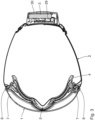
- the glasses shown in their entirety comprise an electrically heatable full-vision spectacle lens 1 and a headband 2 connected to the spectacle lens 1, as well as a power source 3 arranged on the headband 2 for electrically heating the spectacle lens 1.
- a sealing body 4 is arranged on the edge of the lens 1 for contact with the face of a spectacle wearer (not shown).
- the sealing body 4 is elongated and preferably closed in the circumferential direction. It is flexible and made of foam, rubber, or the like, for example.
- the sealing body 4 spatially defines an interior space with the lens 1.
- the spectacle lens 1 has a central region 6 above a central nose recess 5 and, laterally to this, a side region 7, each of which extends to a side edge 8 of the spectacle lens 1. Furthermore, the spectacle lens 1 has an outer side 9 facing away from the wearer when the spectacles are worn and an inner side 10 facing the wearer.
- the spectacle lens 1 is strongly curved.
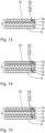
- the spectacle lens 1 comprises a spectacle lens base body 11 and a transparent, electrically conductive coating 12 arranged directly thereon, as well as an anti-fog coating 13 arranged directly above the coating.
- the coating 12 is formed by a plurality of silver nanowires (AgNW).
- a hard or scratch-resistant layer 14 is preferably arranged directly on the base body 11.
- the hard layer 14 forms the outer side 9 and is thus designed as an outer layer.
- a further/second hard layer 14 is present ( Fig. 13 ).
- a transparent, electrically conductive coating 12 is arranged directly on both sides of the base body 11.
- a first coating 12 is directly covered by a hard layer 14 forming the outer side 9, while the other, second coating 12 is directly covered by an anti-fog overcoating 13 forming the inner side 10 ( Fig. 14 ).
- both transparent, electrically conductive coatings 12 are each directly covered by a hard layer 14 ( Fig. 15 ).
- a first hard layer 14 forms the outer side 9, while the other/second hard layer 14 forms the inner side 10.
- the spectacle lens 1 has a plurality of elongated electrical contact means that extend adjacent to or along a peripheral edge 15 of the spectacle lens 1 in the circumferential direction of the spectacle lens 1.
- An upper, lateral contact means 16 and a lower, lateral contact means 17 are arranged in each side region 7.
- An upper, central contact means 18 and a lower, central contact means 19 are arranged in the central region 6.
- the lower, central contact means 19 follows the nose recess 5 and has two legs 20 that extend obliquely to one another.
- the contact means 16, 17, 18, 19 are arranged at a distance from one another in the circumferential direction.
- the upper, lateral contact means 16 and the upper, central contact means 18 extend (essentially) at a common height, while the lower, lateral contact means 17 extend at a common Height.
- the upper, lateral contact means 16 run above the lower, lateral contact means 17, i.e. at a greater height than the lower, lateral contact means 17. They are arranged laterally or in a lateral direction of the spectacle lens 1 (essentially) without offset from one another.
- the upper, central contact means 18 runs above the lower, central contact means 19, i.e. at a greater height than the lower, central contact means 19. They are arranged laterally or in a lateral direction of the spectacle lens 1 (essentially) without offset from one another.
- the contact means 16, 17, 18 and 19 arranged in each region 6, 7 each form an electrical contact means pair. There are three contact means pairs.
- the contact means 16, 17, 18 and 19 are in direct electrical connection with the coating 12 and are preferably covered by the anti-fog overcoating 13 or embedded in it. In particular, they are printed at least to a certain extent and in particular on the edge of the coating 12.
- Each contact means 16, 17, 18 or 19 is in electrical connection with its own electrical conductor track 21, which extends along the peripheral edge 15 and ends in a side end region 22 of the spectacle lens 1, forming an enlarged, flat, exposed contact point 23 ( Fig. 7 , 8 ).
- Each conductor track 21 runs inside and outside with respect to the base body 11 or the spectacle lens 1.
- Figure 6 shows corresponding side changes 27 of the conductor tracks 21 between the inner side 10 and the outer side 9 of the lens 1. With each side change 27, the respective conductor track 21 runs around the outside of the base body 11 or its outer edge ( Figs. 9, 10 ).
- the contact means 16, 17, 18 and 19 are in the embodiment according to Figure 13 again in direct electrical connection with the coating 12 and are covered by the further hard layer 14 forming the inner side 10.
- First contact means 16, 17, 18 and 19 are in the embodiment according to Figure 14 in direct electrical connection with the first coating 12 and are covered by the hard layer 14.
- Second contact means 16, 17, 18, and 19, respectively, are in direct electrical connection with the second coating 12 and are covered by the anti-fog overcoating 13.
- First contact means 16, 17, 18 and 19 are in the embodiment according to Figure 15 in direct electrical connection with a first coating 12 and are covered by the first hard layer 14.
- Second contact means 16, 17, 18 and 19, respectively, are in direct electrical connection with a second coating 12 and are covered by the second hard layer 14.
- the spectacle lens 1 also comprises/carries a sensor/spectacle lens board 24 ( Fig. 4 , 11 ).
- the sensor board 24 is arranged on the inside in the side end region 22 and has pin-like spring contacts 25, at least one sensor 34 and preferably its own microcontroller.
- the spring contacts 25 are identical and their length is resiliently variable. Each spring contact 25 projects vertically from a main plane 35 of the sensor board 24 and is in electrical connection with a contact point 23 of a respective conductor track 21. Due to the curvature of the spectacle lens 1 in the side end region 22, the spring contacts 25 have different lengths; in particular, the length of The length of the upper spring contacts 25 increases from top to bottom, and the length of the lower spring contacts 25 increases from bottom to top.
- the sensor board 24 is preferably covered by a cover.
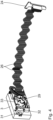
- Each spring contact 25 is in electrical connection with two electrical connecting lines 26 ( Fig. 1 , 2 , 4 , 11 ), which are electrically connected to the sensor board 24.
- the connecting lines 26 run from the sensor board 24 via the headband 2 to the power source 3. They are arranged on the inside of a support body 28 of the headband 2 and are arranged next to one another in a transverse or width direction of the headband 2.
- the connecting lines 26 run parallel to one another. They are arranged in a meandering shape and are thus capable of following a change in the length of the headband 2, such as an increase or decrease in length.
- the connecting lines 26 are locally secured to the support body 28, in particular by means of preferably transparent retaining threads.
- the retaining threads are made of nylon, for example. They are preferably sewn to the support body 28 and each encircle the connecting lines 26.
- the retaining threads securing a connecting line 26 are arranged at a distance from one another along this connecting line 26.
- Each connecting line 26 preferably has a diameter between 0.1 mm and 0.5 mm (without insulation) and between 0.5 mm and 0.8 mm (with insulation).
- the distance between two adjacent extreme points, i.e., a minimum and a maximum, of the connecting lines 26 is advantageously between 5 mm and 15 mm.
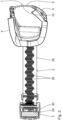
- the connecting lines 26 are electrically connected to a main board 29 ( Fig. 2 , 4 ), which is arranged adjacent to the power source 3.
- the main board 29 and the power source 3 are arranged together in a housing 30.
- the housing 30 carries an on/off switch 31, which is manually operable and, in one setting, allows a power connection between the power source 3 and the main board 29. In an out position, the on/off switch 31 interrupts the power connection between them.
- the housing 30 carries a charging socket 32, which is designed, for example, as a USB socket, in particular a USB-C socket.
- the main board 29, in turn, carries a microcontroller 33 for processing electrical sensor data or signals from the at least one sensor 34 and for applying power to the contact means 16, 17, 18, or 19.
- the lens 1 When the glasses are worn, the lens 1 extends in front of the wearer's eyes and partially runs around their face. The wearer's nose engages in the nose recess 5.
- the housing 30 is located in the back of the wearer's head, opposite the lens 1.
- the microcontroller 33 When the on/off switch 31 is set, the microcontroller 33 is supplied with current from the power source 3. The microcontroller 33 receives corresponding electrical sensor signals from the at least one sensor 34 via the connecting lines 26. If the microcontroller 33 determines that at least partial heating of the spectacle lens 1 is necessary, electrical current is fed from the power source 3 to the sensor board 24 via the respective connecting line 26, which, via the respective spring contact 25, connects the associated conductor track 21 and thus, the associated contact means 16, 17, 18, or 19 is energized. The electrical current thus reaches the coating 12 via the respective contact means 16, 17, 18, or 19. It flows via the coating 12, forming a respective electrical heating zone, to the associated opposite contact means 16, 17, 18, or 19, from where it flows back to the main board 29 via the respective conductor track 21 and the associated spring contact 25, as well as the corresponding connecting line 26.
- the heating power of each heating zone is determined in the embodiment according to Figure 12 In particular, it is set so that the anti-fog overcoating 13 is heated from the inside at maximum saturation, thus expelling the moisture from it. Saturation of the anti-fog overcoating 13 is thus avoided, which permanently prevents fogging and reduces heating power to a minimum.
- the microcontroller 33 of the main board 29 adjusts the heating current accordingly to dehumidify the anti-fog overcoating 13. Power is therefore only supplied to the heating zones when needed. It is expedient if the microcontroller 33 of the main board 29 has/uses an evaluation algorithm for evaluating the sensor signals.
- the moisture or saturation of the anti-fog overcoating 13 or spectacle lens 1 is sensed accordingly by at least one sensor 34.
- the power source 3 supplies the heating zones and the main board 29 with electrical current during operation.
- the base body 11 is heated on both sides.
- Both the anti-fog coating 13 and the hard layer 14 are heated from the inside.
- both hard layers 14 are heated from the inside.
- each heating zone is adjusted in particular so that the anti-fog coating 13 is heated from the inside at maximum saturation, thus expelling the moisture from it. Saturation of the anti-fog coating 13 is thus avoided, which permanently prevents fogging and reduces the heating power to a minimum. Heating is otherwise preferably carried out according to the embodiment according to Figure 12 , the description of which is referred to.
- the spectacle lens 1 is directly equipped with the at least one sensor 34, which is arranged in an edge region of the spectacle lens 1, such as at the bottom side. Furthermore, the spectacle lens 1 is directly equipped with a microcontroller 36, which is arranged in the side end region 22 of the spectacle lens 1.
- the microcontroller 36 forms, for example, the microcontroller of the sensor board 24 and/or the microcontroller 33 of the main board 29.
- the at least one sensor 34 and the contact points 23 are electrically connected to the microcontroller 36 via electrical connecting lines 37. Furthermore, two electrical connection points 38 are arranged in the side region 22, which are connected or connectable to the power source 3 via electrical lines 39 and are electrically connected to the microcontroller 36 via electrical lines 40.
- the connecting lines 37 and lines 40 are also applied directly to the spectacle lens 1.
- the microcontroller 36 is supplied with power from the power source 3.
- the microcontroller 36 receives corresponding electrical signals from the at least one sensor 34 via the associated connecting line 37. If the microcontroller 36 determines that at least partial heating of the spectacle lens 1 is necessary, electrical current is conducted via the respective connecting line 37 via the associated conductor track 21 to the associated contact means 16, 17, 18 or 19, from where the electrical current reaches the coating 12. It flows via the coating 12, forming a respective electrical heating zone, to the associated opposite contact means 16, 17, 18 or 19, from where it flows via the respective conductor track 21 and the corresponding connecting line 37 back to the microcontroller 36. Heating via the heating zones is essentially analogous to the corresponding previous embodiment, to which reference is made.
Landscapes
- Health & Medical Sciences (AREA)
- Ophthalmology & Optometry (AREA)
- Physics & Mathematics (AREA)
- General Health & Medical Sciences (AREA)
- Otolaryngology (AREA)
- Engineering & Computer Science (AREA)
- Biomedical Technology (AREA)
- Heart & Thoracic Surgery (AREA)
- Vascular Medicine (AREA)
- Life Sciences & Earth Sciences (AREA)
- Animal Behavior & Ethology (AREA)
- Public Health (AREA)
- Veterinary Medicine (AREA)
- Optics & Photonics (AREA)
- General Physics & Mathematics (AREA)
- Eyeglasses (AREA)
Description
- Die Erfindung betrifft eine Brillenscheibe gemäß dem Oberbegriff des Anspruchs 1. Ferner richtet sich die Erfindung auf eine Brille mit mindestens einer Brillenscheibe. Die Brille ist insbesondere als Arbeitsschutzbrille oder Wintersport-Brille, wie Skibrille, Snowboardbrille oder dergleichen, ausgeführt.
- Beheizbare Brillenscheiben sind aus dem Stand der Technik allgemein bekannt. Diese haben im Betrieb oftmals einen äußerst hohen Energieverbrauch, was ein häufiges Aufladen bzw. Austauschen von Batterien erfordert. Die Brillen mit solchen Brillenscheiben sind meistens sperrig und schwer aufgrund der eingesetzten Schaltungen bzw. Leiterplatten.
- Die
WO 2015/048564 A1 offenbart gattungsgemäße Antibeschlag-Augenschirme, die beispielsweise in Brillen oder für den Augenschutz einsetzbar sind. Der Augenschirm umfasst ein leitfähiges Heizelement, das in mehrere Bereiche aufgeteilt ist, um beispielsweise ein individuelles Heizen der Bereiche zu ermöglichen. Eine Vielzahl elektrisch leitfähiger Bereiche aus optisch transparentem, elektrisch-resistivem, leitfähigem Heizmaterial ist auf einem Substrat angeordnet. Der Augenschirm umfasst außerdem mindestens zwei Stromschienen, die mit den leitfähigen Bereichen verbunden und ausgebildet sind, um die leitfähigen Bereiche mit der Stromquelle zu verbinden. GemäßFig. 2 sind auf dem Augenschirm drei elektrisch isolierte Heizelementbereiche angeordnet, die mit einer Stromquelle in Verbindung stehen. Das Segmentieren eines Heizelements in mehrere Bereiche ermöglicht die Option, jeden Bereich separat zu beheizen, wie mit separaten Batterien oder mit PWM-Kanalsteuerungen. Die Beheizung dieser Antibeschlag-Augenschirme ist nicht immer zufriedenstellend. - Die
US 2011/0126345 A1 offenbart eine Antibeschlaganordnung, wie Scheiben für den Augenschutz. Eine transparente leitende Schicht ist auf einer Fläche der Scheibe ausgebildet. Eine erste lineare Elektrode ist oben auf der Fläche der Scheibe und eine zweite lineare Elektrode ist unten auf der Fläche der Scheibe angeordnet. Die Enden der Elektroden sind mit einer Energiequelle verbunden. Jedes Ende einer Elektrode ist als Anschlussteil ausgeführt. Die transparente leitende Schicht kann mindestens in einen linken, rechten, oberen und unteren Abschnitt unterteilt sein. Die Elektroden sind dann mit den entsprechenden Bereichen verbunden. - Die
DE 10 2015 114 507 A1 offenbart einen elektrisch beheizbaren Schichtkörper, dessen erster Träger ein- oder beidseitig mit nichttransparenten Leiterbahnen belegt ist. Stark gebündelte Leiterbahnen, wie Kontakte und/oder Anschlüsse, sind im Randbereich angeordnet. Nichttransparente Leiterbahnen, die eine Heizfunktion erfüllen, sind optisch transparent über einen mittigen Bereich verlegt. Die Leiterbahnen bewirken bei Anlegen elektrischen Stroms eine Beheizung des Schichtkörpers, die entweder über die Fläche hinweg gleichmäßig und/oder in einzelnen Flächenbereichen gezielt einstellbar ist. Beispielsweise kann gegenüber den Augen die Heizleistung höher eingestellt sein als beispielsweise im Nasenbereich. - Die
DE 1 951 643 A offenbart eine Schutzbrille mit einer Klarsichtscheibe. Im Inneren der Klarsichtscheibe sind elektrische Heizelemente ausgebildet, die mittels elektrischer Leiter an einer in/an einer Fassung der Klarsichtscheibe beziehungsweise einem Halteband angeordneten Stromquelle anschaltbar sind. Bevorzugt können die Heizelemente und/oder Leiter durch Metallbedampfung, insbesondere von in den Augenbereichen sich erstreckenden Brillenabschnitten, erzielt sein. Sie können auch anderweitig, zum Beispiel durch Widerstandsdrähte oder gedruckte Metallschichten, gebildet sein. Die Klarsichtscheibe ist bevorzugt mit mit den Heizelementen in Verbindung stehenden Kontaktnippeln oder dergleichen ausgerüstet, an die an der Fassung oder dem Tragband festgelegte Stromquellen über elektrische Leiter lösbar ansteckbar sind. Die als Heizelemente dienenden Bedampfungsschichten, Metalldrähte oder dergleichen können sich in oder an der Klarsichtscheibe ausgebildeten Leiterplatten erstrecken. Die Stromquellen sind unmittelbar oder mittels Aufnahmebehälter an der Fassung und/oder Klarsichtscheibe beziehungsweise dem Halteband festgelegt. Diese Brille hat im Betrieb einen hohen Energieverbrauch und ist außerdem sperrig. DieDE 27 18 679 A1 offenbart eine heizbare Sichtscheibe, insbesondere für eine Skibrille, die mit einem Heizelement versehen ist. Das Heizelement ist über einen Feuchtigkeitssensor an eine Stromquelle angeschlossen. Es ist zweckmäßig, wenn das Heizelement durch eine elektrisch leitende Beschichtung gebildet ist, die auf eine Folie angebracht ist, die auf der Innenseite der Sichtscheibe befestigt ist. Auf die Beschichtung sind zwei Flächenkontakte angebracht, an die eine elektrische Spannung anlegbar ist. Diese Sichtscheibe hat sich in der Praxis bewährt. - Der Erfindung liegt die Aufgabe zugrunde, eine verbesserte Brillenscheibe und Brille zu schaffen. Insbesondere sollen die Brillenscheibe und Brille dem Träger einen hohen Komfort bieten und besonders benutzerfreundlich sein.
- Diese Aufgabe wird erfindungsgemäß durch die in den Ansprüchen angegebenen Merkmale gelöst. Der Kern der Erfindung liegt in mindestens einer Beschichtung, die einen Grundkörper der Brillenscheibe be-deckt und mit elektrischen Kontaktmitteln zum elektrischen Beheizen der Brillenscheibe in elektrischer Verbindung steht. Die Kontaktmittel und die mindestens eine Beschichtung sind im Stande, elektrischen Strom bzw. elektrische Spannung zu führen.
- Durch die beidseitige Anordnung von mindestens einer Leiterbahn bzw. von mindestens einem Kontaktmittel ist eine besonders gleichmäßige Aufheizung der Brillenscheibe möglich. Es ist zweckmäßig, wenn jede Leiterbahn bereichsweise auf der Brillenscheibe-Innenseite und Brillenscheibe-Außenseite der Brillenscheibe verläuft.
- Die unabhängig voneinander betätigbaren Heizzonen sind bevorzugt durch die Schaltung betätigbar, wie steuerbar bzw. regelbar. Beispielsweise unterscheiden sich im Betrieb die Heizleistungen der Heizzonen voneinander. Beispielsweise ist mindestens eine Heizzone an, während mindestens eine andere Heizzone gerade aus ist. Ein Betrieb mit reduzierter oder voller Heizleistung ist möglich. Die Heizleistung von jeder Heizzone kann beispielsweise zwischen 0% und 100% liegen. Sie ist bevorzugt stufenlos einstellbar.
- Eine andere bevorzugte Ausgestaltung der Brillenscheibe umfasst einen Grundkörper, mindestens eine transparente, elektrisch leitfähige Beschichtung, die den Grundkörper zumindest bereichsweise bedeckt, und elektrische Kontaktmittel, die die mindestens eine Beschichtung bereichsweise bedecken und mit der mindestens einen Beschichtung in elektrischer Verbindung stehen sowie mindestens eine elektrische Heizzone mit bilden. Die Brillenscheibe hat ferner eine Sensorplatine mit mindestens einem Federkontakt zur elektrischen Verbindung mit Leiterbahnen, wobei die Kontaktmittel mit mindestens einer elektrischen oder elektronischen Schaltung elektrisch verbunden oder verbindbar sind.
- Der mindestens eine Federkontakt sorgt für eine funktionssichere elektrische Verbindung zwischen der Sensorplatine/Brillenscheibenplatine und den Leiterbahnen. Der mindestens eine Federkontakt ist insbesondere im Stande, trotz Krümmung des Grundkörpers bzw. der Brillenscheibe eine sichere elektrische Verbindung dort herzustellen. Er hat bevorzugt mindestens ein federnd verlagerbares, elektrisch leitfähiges Federkontaktmittel, wie Plättchen, Stift oder dergleichen.
- Die Brillenscheibe ist beispielsweise als durchgängige Brillenscheibe, also Vollsichtscheibe, ausgebildet, die sich beim Tragen der Brille vor beiden Augen des Brillenträgers erstreckt. Alternativ ist sie als Brillenscheibe ausgebildet, die sich beim Tragen nur vor genau einem Auge des Brillenträgers erstreckt. Die Brille hat dann zwei nebeneinander angeordnete, getrennte Brillenscheiben. Die Brillenscheibe ist transparent und bevorzugt mehrschichtig. Sie ist beispielsweise getönt. Alternativ ist sie farblos. Es ist zweckmäßig, wenn mit der Brillenscheibe ein Brillenrahmen oder mindestens ein Rahmenteil in Verbindung steht. Günstigerweise ist in der Brillenscheibe und/oder benachbart zu dieser mindestens eine Belüftungsöffnung angeordnet.
- Es ist von Vorteil, wenn der Grundkörper aus Glas und/oder Kunststoff, wie Polycarbonat, gebildet ist. Er ist bevorzugt durch Spritzgießen gebildet. Günstigerweise ist er ein Formkörper.
- Die mindestens eine Beschichtung ist bevorzugt zusammenhängend. Alternativ ist sie beispielsweise durch voneinander getrennte Beschichtungsbereiche gebildet. Die mindestens eine Beschichtung bedeckt vorzugsweise den Grundkörper auf mindestens einer Seite günstigerweise zumindest bereichsweise, bevorzugt zumindest größtenteils, bevorzugt vollständig. Es ist zweckmäßig, wenn sich die Beschichtung innenseitig und/oder außenseitig an/auf dem Grundkörper, also an/auf der dem Brillenträger zugewandten und/oder abgewandten Seite beim Tragen der Brille, befindet. Sie steht mit dem Grundkörper in direkter oder indirekter Verbindung.
- Die mindestens eine Beschichtung ist bevorzugt durch Drähte, insbesondere Nanodrähte, und/oder Partikel gebildet. Es ist zweckmäßig, wenn die mindestens eine Beschichtung elektrisch leitfähiges Metall, wie Silber, aufweist. Vorzugsweise ist die Beschichtung durch oder mit Silber-Nanodrähte(n) gebildet.
- Die elektrischen Kontaktmittel sind vorzugsweise flächig und bevorzugt länglich ausgeführt. Sie sind beispielsweise streifenförmig, leistenförmig oder dergleichen. Die Kontaktmittel erstrecken sich zum Beispiel zumindest bereichsweise gerade, gekrümmt, bogenförmig oder dergleichen. Kombinationen sind möglich. Die Kontaktmittel sind bevorzugt aus einem elektrisch leitfähigen Metall gebildet und mit mindestens einer elektrischen oder elektronischen Schaltung, beispielsweise direkt oder indirekt, unter Bildung eines Stromkreises elektrisch verbunden oder verbindbar. Es ist zweckmäßig, wenn sie mit mindestens einer Energiequelle bzw. Stromquelle, wie Batterie, Akku oder dergleichen, direkt oder indirekt, elektrisch verbunden bzw. verbindbar sind. Der Akku ist bevorzugt kabellos/berührungslos elektrisch aufladbar.
- Jede elektrische Heizzone der Brillenscheibe bedeckt den Grundkörper. Sie ist durch die zugehörigen Kontaktmittel und günstigerweise die mindestens eine Beschichtung gebildet. Jede elektrische Heizzone ist vorzugsweise durch mindestens zwei elektrische Kontaktmittel mit gebildet, die bevorzugt einander gegenüberliegend, günstigerweise in unterschiedlichen Höhen der Brillenscheibe, wie unten und oben, angeordnet sind. Durch unterschiedliche Heizzonen ist eine homogene bzw. gezielte Aufheizung der Brillenscheibe möglich. Es ist zweckmäßig, wenn Heizzyklen situationsabhängig und/oder zeitgesteuert erfolgen.
- Die elektrischen Leiterbahnen sind bevorzugt länglich ausgeführt und verlaufen günstigerweise bereichsweise parallel zueinander. Sie sind aus einem elektrisch leitfähigen Metall gebildet und im Stande, elektrischen Strom bzw. elektrische Spannung zu führen. Die Leiterbahnen sind mit mindestens einer elektrischen oder elektronischen Schaltung, beispielsweise direkt oder indirekt, unter Bildung eines Stromkreises elektrisch verbunden oder verbindbar. Es ist zweckmäßig, wenn sie mit mindestens einer Energiequelle bzw. Stromquelle, wie Batterie, Akku oder dergleichen, direkt oder indirekt, elektrisch verbunden bzw. verbindbar sind.
- Es ist zweckmäßig, wenn mindestens eine elektrische/elektronische Komponente austauschbar ist.
- Günstigerweise hat die Brille zum Tragen derselben mindestens ein Kopf-Haltemittel zum Halten der mindestens einen Brillenscheibe an dem Kopf des Brillenträgers. Das mindestens eine Kopf-Haltemittel ist beispielsweise als Kopfband, Brillenbügel oder dergleichen ausgeführt. Es ist von Vorteil, wenn das Kopfband ein Längenverstellmittel umfasst. Es ist zweckmäßig, wenn die elektrische oder elektronische Schaltung beabstandet zu der Brillenscheibe, beispielsweise an dem Kopf-Haltemittel der Brille und bevorzugt gegenüberliegend zu der Brillenscheibe, angeordnet ist. Dies sorgt für eine besonders gute Gewichtsverteilung und somit einen äußerst hohen Tragekomfort.
- Weitere vorteilhafte Ausgestaltungen der Erfindung sind in den Unteransprüchen angegeben.
- Die Heizzonen gemäß dem Unteranspruch 2 sind beispielsweise getrennt voneinander. Alternativ schließen sich diese direkt aneinander an. Es ist zweckmäßig, wenn zwischen zwei und fünf, bevorzugt zwei oder drei, Heizzonen vorhanden sind.
- Die Leiterbahnen und/oder Kontaktmittel gemäß dem Unteranspruch 3 sind besonders kostengünstig und funktionssicher herstellbar. Sie haben nur einen geringen Platzbedarf.
- Die Antibeschlag-Überbeschichtung gemäß dem Unteranspruch 4 ist bevorzugt durchgängig. Alternativ ist sie durch einzelne Bereiche gebildet. Die Antibeschlag-Überbeschichtung verhindert bzw. verlangsamt einen Beschlag der Brillenscheibe, wenn die mindestens eine Heizzone gerade inaktiv ist, beispielsweise aufgrund einer leeren Stromquelle. Es ist zweckmäßig, wenn die Antibeschlag-Überbeschichtung die mindestens eine Beschichtung und bevorzugt die Kontaktmittel zumindest bereichsweise bedeckt. Sie hat eine freie Seite, die beim Tragen der Brille dem Brillenträger zugewandt ist. Es ist zweckmäßig, wenn die Antibeschlag-Überbeschichtung eine nasschemische Beschichtung ist. Sie steht bevorzugt mit dem Grundkörper in indirekter Verbindung. Es ist von Vorteil, wenn sie mit der mindestens einen Beschichtung in direkter Verbindung steht.
- Es ist zweckmäßig, wenn die Brillenscheibe mindestens einen Sensor für eine Strombeaufschlagung bei Sensieren einer Abweichung von einem Sollwert oder Sollwertbereich aufweist. Der mindestens eine Sensor ermöglicht eine gezielte, bedarfsabhängige Strombeaufschlagung der Kontaktmittel. Er ist beispielsweise im Stande, eine Sättigung der Antibeschlag-Überbeschichtung, eine vorherrschende Temperatur der Brillenscheibe und/oder deren benachbarten Umgebung und/oder eine vorherrschende Feuchte der Brillenscheibe und/oder deren benachbarten Umgebung zu sensieren. Es ist zweckmäßig, wenn der mindestens eine Sensor direkt an der Brillenscheibe angeordnet ist. Alternativ ist dieser beabstandet, aber benachbart zu der Brillenscheibe angeordnet. Der mindestens eine Sensor ist bevorzugt mit der Schaltung, beispielsweise direkt oder indirekt, elektrisch verbunden oder verbindbar. Er ist im Stande, die sensierte/n Größe/Größen in ein entsprechendes, insbesondere weiterverarbeitbares, elektrisches Signal umzuformen.
- Die mindestens eine harte Schicht gemäß dem Unteranspruch 5 führt zu einer besonders kratzfesten Brillenscheibe. Beschädigungen an der Brillenscheibe sind so vermeidbar bzw. reduzierbar. Die mindestens eine harte Schicht steht mit dem Grundkörper in direkter oder indirekter Verbindung. Sie steht mit der mindestens einen Beschichtung in direkter oder indirekter Verbindung. Sie ist innenseitig und/oder außenseitig in Bezug auf den Grundkörper angeordnet. Jede harte Schicht hat eine freie Seite, die beim Tragen der Brille dem Brillenträger zugewandt oder abgewandt ist.
- Der Grundkörper gemäß dem Unteranspruch 6 ist zumindest bereichsweise, wie zweidimensional oder dreidimensional, bevorzugt stark, gekrümmt. Es ist zweckmäßig, wenn die mindestens eine Beschichtung, Antibeschlag-Überbeschichtung, sofern vorhanden, harte Schicht, sofern vorhanden, und mindestens eine Heizzone der Krümmung folgt.
- Es ist von Vorteil, wenn die Brillenscheibe mit mindestens einer Elektronikkomponente und/oder Sensorkomponente direkt bestückt ist. Die Elektronikkomponente ist beispielsweise Bestandteil der Schaltung. Alternativ bildet diese die Schaltung vollständig. Die Elektronikkomponente ist zum Beispiel als Microcontroller ausgeführt. Die Sensorkomponente ist beispielsweise Bestandteil des mindestens einen Sensors. Alternativ bildet diese den mindestens einen Sensor vollständig.
- Es ist von Vorteil, wenn die Brille ein Kopfband zum Halten der Brille an einem Kopf eines Brillenträgers umfasst, wobei das Kopfband aufweist einen biegsamen, elastischen, länglichen Tragkörper und elektrische Verbindungsleitungen zur Verbindung einer Stromquelle mit elektrischen Kontaktmitteln, wobei die Verbindungsleitungen an dem Tragkörper zumindest bereichsweise derart angeordnet sind, dass diese im Stande sind, ihre Länge in einer Längsrichtung des Tragkörpers zu verändern. Die Verbindungsleitungen erlauben eine Größenanpassung des Kopfbands an den Brillenträger, was besonders benutzerfreundlich ist. Es ist zweckmäßig, wenn die Verbindungsleitungen einen Flachbandleiter bilden und bevorzugt zumindest bereichsweise parallel nebeneineinander, wie mäanderartig, schlangenlinienförmig, zickzackförmig oder dergleichen, verlaufen. Sie können zumindest bereichsweise beabstandet zueinander verlaufen oder aneinander anliegen. Sie sind günstigerweise zumindest längs ihrer Längserstreckung an sich undehnbar und bevorzugt elektrisch isoliert.
- Günstigerweise sind die Verbindungsleitungen bereichsweise an dem Tragkörper fixiert.
- Nachfolgend werden unter Bezugnahme auf die beigefügte Zeichnung bevorzugte Ausführungsformen der Erfindung beispielhaft beschrieben. Dabei zeigen:
- Fig. 1
- eine perspektivische Ansicht einer erfindungsgemäßen Brille mit einer Brillenscheibe der Erfindung,
- Fig. 2
- einen Schnitt durch die in
Figur 1 veranschaulichte Brille längs einer ersten Hauptebene der Brille, - Fig. 3
- einen Schnitt durch in
Figur 1 dargestellte Brille längs einer Ebene, die senkrecht zu der Hauptebene gemäßFigur 2 verläuft, - Fig. 4
- eine perspektivische Ansicht, die isoliert elektrische bzw. elektronische Komponenten der in
Figuren 1 bis 3 dargestellten Brille zeigt, - Fig. 5
- ein vereinfachtes Blockschaltbild, das die Wechselwirkung der elektrischen bzw. elektronischen Komponenten der in Figuren 1 bis 3 gezeigten Brille veranschaulicht,
- Fig. 6
- eine Ansicht von außen auf die Brillenscheibe der in
Figuren 1 bis 3 gezeigten Brille, - Fig. 7
- eine Ansicht von innen auf die Brillenscheibe der in
Figuren 1 bis 3 veranschaulichten Brille, - Fig. 8
- einen Seitenbereich der Brillenscheibe der in
Figuren 1 bis 3 gezeigten Brille, - Fig. 9
- einen Schnitt durch die Brillenscheibe der in
Figuren 1 bis 3 veranschaulichten Brille, - Fig. 10
- das in
Figur 9 gekennzeichnete Detail X, - Fig. 11
- eine Seitenansicht der in
Figuren 1 bis 3 dargestellten Brillescheibe, die auch eine Sensorplatine zeigt, - Fig. 12
- eine Schnittansicht, die einen möglichen Aufbau der Brillenscheibe der in
Figuren 1 bis 3 dargestellten Brille veranschaulicht, - Fig. 13 bis 15
- Schnittansichten, die jeweils einen alternativen Aufbau der Brillenscheibe der in
Figuren 1 bis 3 dargestellten Brille zeigen, und - Fig. 16
- einen Seitenbereich einer alternativen Brillenscheibe der in
Figuren 1 bis 3 dargestellten Brille - Einander entsprechende Teile sind in den
Figuren 1 bis 16 mit denselben Bezugszeichen versehen. Auch Einzelheiten der im Folgenden näher erläuterten bevorzugten Ausführungsformen können für sich genommen eine Erfindung darstellen oder Teil eines Erfindungsgegenstands sein. - Eine in
Figuren 1 bis 3 in ihrer Gesamtheit dargestellte Brille umfasst eine elektrisch beheizbare Vollsicht-Brillenscheibe 1 und ein mit der Brillenscheibe 1 in Verbindung stehendes Kopfband 2 sowie eine an dem Kopfband 2 angeordnete Stromquelle 3 für ein elektrisches Beheizen der Brillenscheibe 1. - An der Brillenscheibe 1 ist randseitig ein Dichtkörper 4 zur Anlage an einem Gesicht eines Brillenträgers (nicht dargestellt) angeordnet. Der Dichtkörper 4 ist länglich und bevorzugt in Umfangsrichtung geschlossen. Er ist nachgiebig und beispielsweise aus Schaumstoff, Gummi oder dergleichen ausgeführt. Der Dichtkörper 4 begrenzt räumlich mit der Brillenscheibe 1 einen Innenraum.
- Die Brillenscheibe 1 weist über einer zentralen Nasenaussparung 5 einen zentralen Bereich 6 und seitlich zu diesem jeweils einen Seitenbereich 7 auf, der sich jeweils bis zu einem Seitenrand 8 der Brillenscheibe 1 erstreckt. Ferner hat die Brillenscheibe 1 eine in getragenem Zustand der Brille dem Brillenträger abgewandte Außenseite 9 und eine diesem dann zugewandte Innenseite 10. Die Brillenscheibe 1 ist stark gekrümmt.
- Die Brillenscheibe 1 umfasst einen Brillenscheiben-Grundkörper 11 und eine auf diesem direkt angeordnete, transparente, elektrisch leitfähige Beschichtung 12 sowie eine direkt über dieser angeordnete Antibeschlag-Überbeschichtung 13. Die Beschichtung 12 ist durch eine Vielzahl von Silber-Nanodrähten (AgNW) gebildet. Gegenüberliegend zu der Beschichtung 12 ist vorzugsweise direkt auf dem Grundkörper 11 eine harte bzw. kratzfeste Schicht 14 angeordnet. Die harte Schicht 14 bildet die Außenseite 9 aus und ist somit als Außenschicht ausgeführt. Die Antibeschlag-Überbeschichtung 13 bildet dagegen die Innenseite 10 aus und ist als Innenschicht ausgeführt (siehe
Fig. 12 ). - Gemäß einer alternativen Ausführungsform ist anstelle der Antibeschlag-Überbeschichtung 13 eine weitere/zweite harte Schicht 14 vorhanden (
Fig. 13 ). - Gemäß einer alternativen Ausführungsform ist beidseits des Grundkörpers 11 jeweils direkt eine transparente, elektrisch leitfähige Beschichtung 12 angeordnet. Eine erste Beschichtung 12 ist direkt von einer die Außenseite 9 ausbildenden, harten Schicht 14 bedeckt, während die andere, zweite Beschichtung 12 direkt von einer die Innenseite 10 ausbildenden Antibeschlag-Überbeschichtung 13 bedeckt ist (
Fig. 14 ). - Alternativ sind beide transparenten, elektrisch leitfähigen Beschichtungen 12 jeweils direkt von einer harten Schicht 14 bedeckt (
Fig. 15 ). Eine erste harte Schicht 14 bildet die Außenseite 9 aus, während die andere/zweite harte Schicht 14 die Innenseite 10 ausbildet. - Kombinationen bzw. ein anderer Schichtaufbau ist/sind alternativ möglich.
- Wie beispielsweise
Figur 7 zeigt, hat die Brillenscheibe 1 mehrere, längliche, elektrische Kontaktmittel, die sich benachbart bzw. längs eines Umfangsrands 15 der Brillenscheibe 1 in Umfangsrichtung der Brillenscheibe 1 erstrecken. In jedem Seitenbereich 7 sind ein oberes, seitliches Kontaktmittel 16 und ein unteres, seitliches Kontaktmittel 17 angeordnet. In dem zentralen Bereich 6 sind ein oberes, zentrales Kontaktmittel 18 und ein unteres, zentrales Kontaktmittel 19 angeordnet. Das untere, zentrale Kontaktmittel 19 folgt der Nasenaussparung 5 und hat zwei schräg zueinander verlaufende Schenkel 20. - Die Kontaktmittel 16, 17, 18, 19 sind in Umfangsrichtung beabstandet zueinander angeordnet. Die oberen, seitlichen Kontaktmittel 16 und das obere, zentrale Kontaktmittel 18 verlaufen (im Wesentlichen) in einer gemeinsamen Höhe, während die unteren, seitlichen Kontaktmittel 17 in einer gemeinsamen Höhe verlaufen. Die oberen, seitlichen Kontaktmittel 16 verlaufen oberhalb der unteren, seitlichen Kontaktmittel 17, das heißt in einer größeren Höhe als die unteren, seitlichen Kontaktmittel 17. Sie sind seitlich bzw. in einer Seitenrichtung der Brillenscheibe 1 (im Wesentlichen) unversetzt zueinander angeordnet. Das obere, zentrale Kontaktmittel 18 verläuft oberhalb des unteren, zentralen Kontaktmittels 19, das heißt in einer größeren Höhe als das untere, zentrale Kontaktmittel 19. Sie sind seitlich bzw. in einer Seitenrichtung der Brillenscheibe 1 (im Wesentlichen) unversetzt zueinander angeordnet. Die in jedem Bereich 6, 7 angeordneten Kontaktmittel 16, 17, 18 bzw. 19 bilden jeweils ein elektrisches Kontaktmittel-Paar. Es sind drei Kontaktmittel-Paare vorhanden. Die Kontaktmittel 16, 17, 18 bzw. 19 stehen mit der Beschichtung 12 in direkter elektrischer Verbindung und sind bevorzugt von der Antibeschlag-Überbeschichtung 13 bedeckt bzw. in diese eingebettet. Sie sind insbesondere zumindest zu einem gewissen Teil und insbesondere randseitig auf die Beschichtung 12 aufgedruckt.
- Jedes Kontaktmittel 16, 17, 18 bzw. 19 steht in elektrischer Verbindung mit einer eigenen, elektrischen Leiterbahn 21, die sich längs des Umfangsrands 15 erstreckt und in einem Seitenendbereich 22 der Brillenscheibe 1 unter Bildung einer vergrößerten, flächigen, freiliegenden Kontaktstelle 23 endet (
Fig. 7 ,8 ). Jede Leiterbahn 21 verläuft innenseitig und außenseitig in Bezug auf den Grundkörper 11 bzw. die Brillenscheibe 1.Figur 6 zeigt entsprechende Seitenwechsel 27 der Leiterbahnen 21 zwischen der Innenseite 10 und der Außenseite 9 der Brillenscheibe 1. Bei jedem Seitenwechsel 27 läuft die jeweilige Leiterbahn 21 außen um den Grundkörper 11 bzw. dessen Außenrand herum (Fig. 9, 10 ). - Die Kontaktmittel 16, 17, 18 bzw. 19 stehen bei der Ausführungsform gemäß
Figur 13 wieder mit der Beschichtung 12 in direkter elektrischer Verbindung und sind von der weiteren, also die Innenseite 10 ausbildenden, harten Schicht 14 bedeckt. - Erste Kontaktmittel 16, 17, 18 bzw. 19 stehen bei der Ausführungsform gemäß
Figur 14 mit der ersten Beschichtung 12 in direkter elektrischer Verbindung und sind von der harten Schicht 14 bedeckt. Zweite Kontaktmittel 16, 17, 18 bzw. 19 stehen mit der zweiten Beschichtung 12 in direkter elektrischer Verbindung und sind von der Antibeschlag-Überbeschichtung 13 bedeckt. - Erste Kontaktmittel 16, 17, 18 bzw. 19 stehen bei der Ausführungsform gemäß
Figur 15 mit einer ersten Beschichtung 12 in direkter elektrischer Verbindung und sind von der ersten harten Schicht 14 bedeckt. Zweite Kontaktmittel 16, 17, 18 bzw. 19 stehen mit einer zweiten Beschichtung 12 in direkter elektrischer Verbindung und sind von der zweiten harten Schicht 14 bedeckt. - Die Brillenscheibe 1 umfasst/trägt außerdem eine Sensor-/Brillenscheibenplatine 24 (
Fig. 4 ,11 ). Die Sensorplatine 24 ist in dem Seitenendbereich 22 innenseitig angeordnet und weist stiftartige Federkontakte 25, mindestens einen Sensor 34 und bevorzugt einen eigenen Microcontroller auf. Die Federkontakte 25 sind identisch ausgeführt und in ihrer Länge federnd veränderlich. Jeder Federkontakt 25 springt von einer Hauptebene 35 der Sensorplatine 24 senkrecht vor und steht mit einer Kontaktstelle 23 einer jeweiligen Leiterbahn 21 in elektrischer Verbindung. Aufgrund der Krümmung der Brillenscheibe 1 in dem Seitenendbereich 22 haben die Federkontakte 25 unterschiedliche Längen; insbesondere nimmt die Länge von oberen Federkontakten 25 von oben nach unten zu und die Länge von unteren Federkontakten 25 von unten nach oben zu. Die Sensorplatine 24 ist bevorzugt von einer Abdeckung abgedeckt. - Jeder Federkontakt 25 steht in elektrischer Verbindung mit zwei elektrischen Verbindungsleitungen 26 (
Fig. 1 ,2 ,4 ,11 ), die an die Sensorplatine 24 elektrisch angeschlossen sind. Die Verbindungsleitungen 26 verlaufen von der Sensorplatine 24 über das Kopfband 2 zu der Stromquelle 3. Sie sind innenseitig an einem Tragkörper 28 des Kopfbands 2 angeordnet und sind in einer Quer- bzw. Breitenrichtung des Kopfbands 2 nebeneinander angeordnet. Die Verbindungsleitungen 26 verlaufen parallel zueinander. Sie sind mäanderförmig angeordnet und so im Stande, eine Längenveränderung des Kopfbands 2, wie Längenzunahme oder Längenabnahme, mitzumachen. - Die Verbindungsleitungen 26 sind an dem Tragkörper 28 lokal, insbesondere mittels, bevorzugt transparenten, Haltefäden, fixiert. Die Haltefäden bestehen beispielsweise aus Nylon. Sie sind vorzugsweise mit dem Tragkörper 28 vernäht und umlaufen jeweils die Verbindungsleitungen 26. Die eine Verbindungsleitung 26 fixierenden Haltefäden sind längs dieser Verbindungsleitung 26 beabstandet zueinander angeordnet.
- Jede Verbindungsleitung 26 hat bevorzugt einen Durchmesser, der zwischen 0,1 mm und 0,5 mm (ohne Isolierung) und zwischen 0,5 mm und 0,8 mm (mit Isolierung) liegt. In ungedehntem Zustand des Kopfbands 2 liegt der Abstand zwischen zwei benachbarten Extremstellen, also einem Minimum und einem Maximum, der Verbindungsleitungen 26 günstigerweise zwischen 5 mm und 15 mm.
- Die Verbindungsleitungen 26 sind an eine Hauptplatine 29 elektrisch angeschlossen (
Fig. 2 ,4 ), die benachbart zu der Stromquelle 3 angeordnet ist. Die Hauptplatine 29 und die Stromquelle 3 sind gemeinsam in einem Gehäuse 30 angeordnet. Das Gehäuse 30 trägt einen Ein-/Aussschalter 31, der manuell betätigbar ist und in einer Einstellung eine Stromverbindung zwischen der Stromquelle 3 und der Hauptplatine 29 erlaubt. In einer Ausstellung unterbricht der Ein-/Aussschalter 31 die Stromverbindung zwischen diesen. Ferner trägt das Gehäuse 30 eine Ladebuchse 32, die beispielsweise als USB-Buchse, insbesondere USB-C-Buchse, ausgeführt ist. Die Hauptplatine 29 wiederum trägt einen Microcontroller 33 zur Verarbeitung elektrischer Sensordaten bzw. -signale des mindestens einen Sensors 34 und zur Strombeaufschlagung der Kontaktmittel 16, 17, 18 bzw. 19. - Nachfolgend wird der Einsatz der Brille näher beschrieben.
- Die Brillenscheibe 1 erstreckt sich in getragenem Zustand der Brille vor den Augen des Brillenträgers und läuft bereichsweise um dessen Gesicht. Die Nase des Brillenträgers greift in die Nasenaussparung 5 ein. Das Gehäuse 30 befindet sich im Hinterkopfbereich des Brillenträgers gegenüberliegend zu der Brillenscheibe 1.
- In der Einstellung des Ein-/Ausschalters 31 wird der Microcontroller 33 mit Strom von der Stromquelle 3 beaufschlagt. Der Microcontroller 33 empfängt von dem mindestens einen Sensor 34 entsprechende elektrische Sensorsignale über die Verbindungsleitungen 26. Wenn der Microcontroller 33 feststellt, dass eine zumindest teilweise Beheizung der Brillenscheibe 1 notwendig ist, wird über die jeweilige Verbindungsleitung 26 elektrischer Strom aus der Stromquelle 3 zu der Sensorplatine 24 geführt, die über den jeweiligen Federkontakt 25 die zugehörige Leiterbahn 21 und somit das zugeordnete Kontaktmittel 16, 17, 18 bzw. 19 mit Strom beaufschlagt. Der elektrische Strom gelangt so über das jeweilige Kontaktmittel 16, 17, 18 bzw. 19 zu der Beschichtung 12. Er fließt über die Beschichtung 12 unter Bildung einer jeweiligen elektrischen Heizzone zu dem zugeordneten gegenüberliegenden Kontaktmittel 16, 17, 18 bzw. 19, von wo er über die jeweilige Leiterbahn 21 und dem zugehörigen Federkontakt 25 sowie die entsprechende Verbindungsleitung 26 zurück zu der Hauptplatine 29 fließt.
- Die Heizleistung von jeder Heizzone wird bei der Ausführungsform gemäß
Figur 12 insbesondere so eingestellt, dass die Antibeschlag-Überbeschichtung 13 bei maximaler Sättigung von innen beheizt und so die Feuchtigkeit wieder aus dieser ausgetrieben wird. Eine Sättigung der Antibeschlag-Überbeschichtung 13 bleibt so aus, was ein Beschlagen derselben dauerhaft verhindert und die Heizleistung auf ein Minimum reduziert. Der Microcontroller 33 der Hauptplatine 29 stellt entsprechend den Heizstrom ein, um die Antibeschlag-Überbeschichtung 13 zu entfeuchten. Eine Stromzufuhr zu den Heizzonen erfolgt demnach nur bei Bedarf. Es ist zweckmäßig, wenn der Microcontroller 33 der Hauptplatine 29 einen Auswertealgorithmus zur Auswertung der Sensorsignale aufweist/nutzt. Die Feuchtigkeit bzw. Sättigung der Antibeschlag-Überbeschichtung 13 bzw. Brillenscheibe 1 wird entsprechend durch den mindestens einen Sensor 34 sensiert. Die Stromquelle 3 versorgt die Heizzonen und die Hauptplatine 29 mit elektrischem Strom im Betrieb. - Bei den Ausführungsformen gemäß
Figuren 13 und 15 wird bei dem Beheizen die Kondensation von Feuchtigkeit auf der Innenseite 10 verhindert, die jeweils an der harten Schicht 14 ausgebildet ist. Die harten Schichten 14 werden jeweils von innen beheizt. Das Beheizen erfolgt ansonsten bevorzugt gemäß der Ausführungsform gemäßFigur 12 , auf deren Beschreibung verwiesen wird. - Bei den Ausführungsformen gemäß
Figuren 14, 15 wird der Grundkörper 11 beidseitig erwärmt. Bei der Ausführungsform gemäßFigur 14 werden sowohl die Antibeschlag-Überbeschichtung 13 als auch die harte Schicht 14 von innen beheizt. Bei der Ausführungsform gemäßFigur 15 werden beide harte Schichten 14 von innen beheizt. - Bei der Ausführungsform gemäß
Figur 14 wird die Heizleistung von jeder Heizzone insbesondere so eingestellt, dass die Antibeschlag-Überbeschichtung 13 bei maximaler Sättigung von innen beheizt und so die Feuchtigkeit wieder aus dieser ausgetrieben wird. Eine Sättigung der Antibeschlag-Überbeschichtung 13 bleibt so aus, was ein Beschlagen derselben dauerhaft verhindert und die Heizleistung auf ein Minimum reduziert. Das Beheizen erfolgt ansonsten bevorzugt gemäß der Ausführungsform gemäßFigur 12 , auf deren Beschreibung verwiesen wird. - Nachfolgend wird unter Bezugnahme auf
Figur 16 eine alternative Ausbildung der Brillenscheibe 1 beschrieben. Im Vergleich mit der Brillenscheibe 1 gemäßFiguren 8 ,11 , auf deren Beschreibung verwiesen wird, ist die Brillenscheibe 1 gemäß dieser Ausführungsform direkt mit dem mindestens einen Sensor 34 bestückt, der in einem Randbereich der Brillenscheibe 1, wie seitlich unten, angeordnet ist. Ferner ist die Brillenscheibe 1 direkt mit einem Microcontroller 36 bestückt, der in dem Seitenendbereich 22 der Brillenscheibe 1 angeordnet ist. Der Microcontroller 36 bildet beispielsweise den Microcontroller der Sensorplatine 24 und/oder den Microcontroller 33 der Hauptplatine 29. - Der mindestens eine Sensor 34 und die Kontaktstellen 23 stehen über elektrische Anschlussleitungen 37 mit dem Microcontroller 36 in elektrischer Verbindung. Ferner sind in dem Seitenbereich 22 zwei elektrische Anschlussstellen 38 angeordnet, die mit der Stromquelle 3 über elektrische Leitungen 39 verbunden bzw. verbindbar und mit dem Microcontroller 36 über elektrische Leitungen 40 elektrisch verbunden sind. Die Anschlussleitungen 37 und Leitungen 40 sind ebenfalls direkt auf die Brillenscheibe 1 aufgebracht.
- Im Betrieb wird der Microcontroller 36 mit Strom von der Stromquelle 3 beaufschlagt. Der Microcontroller 36 empfängt von dem mindestens einen Sensor 34 entsprechende elektrische Signale über die zugehörige Anschlussleitung 37. Wenn der Microcontroller 36 feststellt, dass eine zumindest teilweise Beheizung der Brillenscheibe 1 notwendig ist, wird über die jeweilige Anschlussleitung 37 elektrischer Strom über die zugehörige Leiterbahn 21 zu dem zugeordneten Kontaktmittel 16, 17, 18 bzw. 19 geführt, von wo der elektrische Strom zu der Beschichtung 12 gelangt. Er fließt über die Beschichtung 12 unter Bildung einer jeweiligen elektrischen Heizzone zu dem zugeordneten gegenüberliegenden Kontaktmittel 16, 17, 18 bzw. 19, von wo er über die jeweilige Leiterbahn 21 und die entsprechende Anschlussleitung 37 zurück zu dem Microcontroller 36 fließt. Die Beheizung über die Heizzonen erfolgt im Wesentlichen analog wie bei der entsprechenden vorherigen Ausführungsform, auf die verwiesen wird.
Claims (9)
- Brillenscheibea) mit einem Grundkörper (11),b) mit mindestens einer transparenten, elektrisch leitfähigen Beschichtung (12), die den Grundkörper (11) zumindest bereichsweise bedeckt,c) mit elektrischen Kontaktmitteln (16, 17, 18, 19), diei) die mindestens eine Beschichtung (12) bereichsweise bedecken,ii) mit der mindestens einen Beschichtung (12) in elektrischer Verbindung stehen, undiii) mindestens zwei elektrische Heizzonen mit bilden, die unabhängig voneinander betätigbar sind, undd) mit elektrischen Leiterbahnen (21), die mit den Kontaktmitteln (16, 17, 18, 19) zur Strombeaufschlagung derselben elektrisch verbunden sind,
dadurch gekennzeichnet, dasse) zumindest eine der Leiterbahnen (21) bereichsweise auf einer Brillenscheiben-Innenseite (10) und bereichsweise auf einer Brillenscheiben-Außenseite (9) verläuft. - Brillenscheibe nach Anspruch 1, dadurch gekennzeichnet, dass die Heizzonen nebeneinander angeordnet sind.
- Brillenscheibe nach Anspruch 1 oder 2, dadurch gekennzeichnet, dass die Leiterbahnen (21) und/oder Kontaktmittel (16, 17, 18, 19) aufgedruckt sind.
- Brillenscheibe nach einem der vorherigen Ansprüche, gekennzeichnet durch eine transparente, wasserabsorbierende, innere Antibeschlag-Überbeschichtung (13).
- Brillenscheibe nach einem der vorherigen Ansprüche, gekennzeichnet durch mindestens eine transparente, harte Schicht (14), die den Grundkörper (11) zumindest bereichsweise bedeckt.
- Brillenscheibe nach einem der vorherigen Ansprüche, dadurch gekennzeichnet, dass der Grundkörper (11) zumindest bereichsweise gekrümmt ist.
- Brillenscheibe nach einem der vorherigen Ansprüche, dadurch gekennzeichnet, dass bei der mindestens einen bereichsweise auf der Brillenscheiben-Innenseite (10) und bereichsweise auf der Brillenscheiben-Außenseite (9) verlaufenden Leiterbahn (21) ein Seitenwechsel (27) zwischen der Brillenscheiben-Innenseite (10) und Brillenscheiben-Außenseite (9) vorliegt.
- Brillenscheibe nach Anspruch 7, dadurch gekennzeichnet, dass bei jedem Seitenwechsel (27) die jeweilige Leiterbahn (21) außen um den Grundkörper (11) herumläuft.
- Brille mit mindestens einer Brillenscheibe (1) nach einem der vorherigen Ansprüche.
Applications Claiming Priority (2)
| Application Number | Priority Date | Filing Date | Title |
|---|---|---|---|
| DE102021201180.2A DE102021201180B3 (de) | 2021-02-09 | 2021-02-09 | Brillenscheibe und Brille |
| PCT/EP2022/051308 WO2022171415A1 (de) | 2021-02-09 | 2022-01-21 | Brillenscheibe |
Publications (2)
| Publication Number | Publication Date |
|---|---|
| EP4291945A1 EP4291945A1 (de) | 2023-12-20 |
| EP4291945B1 true EP4291945B1 (de) | 2025-04-02 |
Family
ID=80050800
Family Applications (1)
| Application Number | Title | Priority Date | Filing Date |
|---|---|---|---|
| EP22700982.6A Active EP4291945B1 (de) | 2021-02-09 | 2022-01-21 | Brillenscheibe |
Country Status (5)
| Country | Link |
|---|---|
| US (1) | US12599503B2 (de) |
| EP (1) | EP4291945B1 (de) |
| AU (1) | AU2022219416A1 (de) |
| DE (1) | DE102021201180B3 (de) |
| WO (1) | WO2022171415A1 (de) |
Families Citing this family (1)
| Publication number | Priority date | Publication date | Assignee | Title |
|---|---|---|---|---|
| USD1121709S1 (en) * | 2023-11-29 | 2026-04-07 | Milwaukee Electric Tool Corporation | Protective eyewear |
Citations (8)
| Publication number | Priority date | Publication date | Assignee | Title |
|---|---|---|---|---|
| EP1072205A2 (de) * | 1999-07-02 | 2001-01-31 | Bayerische Motoren Werke Aktiengesellschaft | Heizeinrichtung für einen Sichtkörper eines Schutzhelms oder einer Schutzbrille |
| DE202009010212U1 (de) * | 2009-07-28 | 2010-01-07 | Huynh, Quang-Ut | Elektrisches Dünnschichtheizsystem für Helmvisiere |
| US20130212765A1 (en) * | 2012-02-16 | 2013-08-22 | Jack Cornelius | Pwm heating system for eye shield |
| WO2017070628A1 (en) * | 2015-10-23 | 2017-04-27 | Abominable Labs, Llc | Electrical interconnection system for heating eye-shield |
| US20180000648A1 (en) * | 2015-01-27 | 2018-01-04 | Abominable Labs, Llc | Interchangeable lens goggle adaptable to prevent fogging |
| US20180014359A1 (en) * | 2015-01-28 | 2018-01-11 | Commissariat A L'energie Atomique Et Aux Energies Al Ternatives | Heating device, in particular a semi-transparent heating device |
| US20180124878A1 (en) * | 2010-06-07 | 2018-05-03 | SMR Patents S.à.r.l. | Rear-view Assembly for a Motor Vehicle with a Heating Device |
| EP3709775A1 (de) * | 2017-11-07 | 2020-09-16 | Dai Nippon Printing Co., Ltd. | Dehnbares schaltungssubstrat und artikel |
Family Cites Families (9)
| Publication number | Priority date | Publication date | Assignee | Title |
|---|---|---|---|---|
| DE1951643A1 (de) | 1969-10-14 | 1971-04-22 | Erik Kindermann | Schutzbrille |
| DE2718679C3 (de) | 1977-04-27 | 1980-08-21 | Uvex Winter Optik Gmbh, 8510 Fuerth | Heizbare Sichtscheibe für eine Skibrille |
| CA2658469C (en) | 2008-10-03 | 2012-08-14 | Rajender P. Gupta | Bromination process |
| JP5344346B2 (ja) * | 2009-12-02 | 2013-11-20 | 山本光学株式会社 | 防曇レンズ類及び眼用保護具 |
| WO2013078442A1 (en) * | 2011-11-25 | 2013-05-30 | David Mcculloch | Modular anti-fog goggle system |
| WO2013169987A1 (en) * | 2012-05-10 | 2013-11-14 | Oakley, Inc. | Eyewear with laminated functional layers |
| AU2014324661A1 (en) * | 2013-09-29 | 2016-05-12 | Abominable Labs, Llc | Multiregion heated eye shield |
| DE102015114507A1 (de) * | 2015-08-31 | 2017-03-02 | Polyic Gmbh & Co. Kg | Beheizbarer Schichtkörper, Verfahren zur Aufbringung und beheizbare Scheibe |
| US11994750B2 (en) * | 2021-01-07 | 2024-05-28 | Polaris Industries Inc. | Goggle with anti-fog lens |
-
2021
- 2021-02-09 DE DE102021201180.2A patent/DE102021201180B3/de active Active
-
2022
- 2022-01-21 EP EP22700982.6A patent/EP4291945B1/de active Active
- 2022-01-21 WO PCT/EP2022/051308 patent/WO2022171415A1/de not_active Ceased
- 2022-01-21 AU AU2022219416A patent/AU2022219416A1/en active Pending
- 2022-01-21 US US18/264,092 patent/US12599503B2/en active Active
Patent Citations (8)
| Publication number | Priority date | Publication date | Assignee | Title |
|---|---|---|---|---|
| EP1072205A2 (de) * | 1999-07-02 | 2001-01-31 | Bayerische Motoren Werke Aktiengesellschaft | Heizeinrichtung für einen Sichtkörper eines Schutzhelms oder einer Schutzbrille |
| DE202009010212U1 (de) * | 2009-07-28 | 2010-01-07 | Huynh, Quang-Ut | Elektrisches Dünnschichtheizsystem für Helmvisiere |
| US20180124878A1 (en) * | 2010-06-07 | 2018-05-03 | SMR Patents S.à.r.l. | Rear-view Assembly for a Motor Vehicle with a Heating Device |
| US20130212765A1 (en) * | 2012-02-16 | 2013-08-22 | Jack Cornelius | Pwm heating system for eye shield |
| US20180000648A1 (en) * | 2015-01-27 | 2018-01-04 | Abominable Labs, Llc | Interchangeable lens goggle adaptable to prevent fogging |
| US20180014359A1 (en) * | 2015-01-28 | 2018-01-11 | Commissariat A L'energie Atomique Et Aux Energies Al Ternatives | Heating device, in particular a semi-transparent heating device |
| WO2017070628A1 (en) * | 2015-10-23 | 2017-04-27 | Abominable Labs, Llc | Electrical interconnection system for heating eye-shield |
| EP3709775A1 (de) * | 2017-11-07 | 2020-09-16 | Dai Nippon Printing Co., Ltd. | Dehnbares schaltungssubstrat und artikel |
Also Published As
| Publication number | Publication date |
|---|---|
| AU2022219416A9 (en) | 2024-08-01 |
| WO2022171415A1 (de) | 2022-08-18 |
| DE102021201180B3 (de) | 2022-05-05 |
| US20240082062A1 (en) | 2024-03-14 |
| EP4291945A1 (de) | 2023-12-20 |
| AU2022219416A1 (en) | 2023-07-13 |
| US12599503B2 (en) | 2026-04-14 |
Similar Documents
| Publication | Publication Date | Title |
|---|---|---|
| EP1569551B1 (de) | Medizinische elektrode | |
| DE69532622T2 (de) | Flächenheizelement zur Verwendung bei Spiegeln | |
| EP2336819B1 (de) | Beschlagbeständige Struktur und Schutzvorrichtung für die Augen | |
| US20180325736A1 (en) | Electrical interconnection system for heating eye-shield | |
| DE112012000006T5 (de) | Fussbekleidungsstück mit Drucksensor | |
| EP3165761B1 (de) | Windenergieanlagenrotorblatt mit einer elektrischen heizeinrichtung | |
| US9210737B2 (en) | Multiregion heated eye shield | |
| DE3004126A1 (de) | Elektrode zum abnehmen von bioelektrischen signalen | |
| DE112019003797B4 (de) | Fahrzeugwindschutzscheibenvorrichtung mit flächigem Wärmeerzeugungskörper | |
| WO2012092632A1 (de) | Medizinische elektrode mit gedruckter, abgeschirmter zuleitung | |
| DE102008029727A1 (de) | Heizvorrichtung und Einlegesohle mit Heizvorrichtung | |
| DE10220041A1 (de) | Sportbrille | |
| DE202013007659U1 (de) | Windenergieanlagenrotorblatt mit einem elektrischen Heizelement | |
| EP2021068B1 (de) | Oberflächenelektrode | |
| KR20160066035A (ko) | 멀티영역 가열되는 보안경 | |
| DE202022102476U1 (de) | Beheizbare Vorrichtung zur Verwendung mit einer an einem Fahrzeug montierten Bilderfassungseinheit | |
| EP2865411A1 (de) | Stimulationsvorrichtung | |
| DE102018113203A1 (de) | Insasseninformations-Erfassungssensor für Lenkrad | |
| DE102021201180B3 (de) | Brillenscheibe und Brille | |
| DE102012004117A1 (de) | Sohle mit Sensor | |
| EP0824874B1 (de) | Innenschuh, insbesondere für Skischuhe, Bergschuhe od.dgl | |
| US7211768B2 (en) | Heating line pattern structure of defogger | |
| DE3325425A1 (de) | Verstellbares brillengestell | |
| DE10314094A1 (de) | Antennenscheibe | |
| DE4000259C1 (en) | Electrically heatable sole with temp.-control circuit - embedded with temp. sensors in plastics material layer with power from batteries in further plastics material layer |
Legal Events
| Date | Code | Title | Description |
|---|---|---|---|
| STAA | Information on the status of an ep patent application or granted ep patent |
Free format text: STATUS: UNKNOWN |
|
| STAA | Information on the status of an ep patent application or granted ep patent |
Free format text: STATUS: THE INTERNATIONAL PUBLICATION HAS BEEN MADE |
|
| PUAI | Public reference made under article 153(3) epc to a published international application that has entered the european phase |
Free format text: ORIGINAL CODE: 0009012 |
|
| STAA | Information on the status of an ep patent application or granted ep patent |
Free format text: STATUS: REQUEST FOR EXAMINATION WAS MADE |
|
| 17P | Request for examination filed |
Effective date: 20230620 |
|
| AK | Designated contracting states |
Kind code of ref document: A1 Designated state(s): AL AT BE BG CH CY CZ DE DK EE ES FI FR GB GR HR HU IE IS IT LI LT LU LV MC MK MT NL NO PL PT RO RS SE SI SK SM TR |
|
| P01 | Opt-out of the competence of the unified patent court (upc) registered |
Effective date: 20231222 |
|
| DAV | Request for validation of the european patent (deleted) | ||
| DAX | Request for extension of the european patent (deleted) | ||
| GRAP | Despatch of communication of intention to grant a patent |
Free format text: ORIGINAL CODE: EPIDOSNIGR1 |
|
| STAA | Information on the status of an ep patent application or granted ep patent |
Free format text: STATUS: GRANT OF PATENT IS INTENDED |
|
| INTG | Intention to grant announced |
Effective date: 20241125 |
|
| GRAS | Grant fee paid |
Free format text: ORIGINAL CODE: EPIDOSNIGR3 |
|
| GRAA | (expected) grant |
Free format text: ORIGINAL CODE: 0009210 |
|
| STAA | Information on the status of an ep patent application or granted ep patent |
Free format text: STATUS: THE PATENT HAS BEEN GRANTED |
|
| AK | Designated contracting states |
Kind code of ref document: B1 Designated state(s): AL AT BE BG CH CY CZ DE DK EE ES FI FR GB GR HR HU IE IS IT LI LT LU LV MC MK MT NL NO PL PT RO RS SE SI SK SM TR |
|
| REG | Reference to a national code |
Ref country code: GB Ref legal event code: FG4D Free format text: NOT ENGLISH |
|
| REG | Reference to a national code |
Ref country code: CH Ref legal event code: EP |
|
| REG | Reference to a national code |
Ref country code: DE Ref legal event code: R096 Ref document number: 502022003416 Country of ref document: DE |
|
| REG | Reference to a national code |
Ref country code: IE Ref legal event code: FG4D Free format text: LANGUAGE OF EP DOCUMENT: GERMAN |
|
| REG | Reference to a national code |
Ref country code: NL Ref legal event code: MP Effective date: 20250402 |
|
| PG25 | Lapsed in a contracting state [announced via postgrant information from national office to epo] |
Ref country code: NL Free format text: LAPSE BECAUSE OF FAILURE TO SUBMIT A TRANSLATION OF THE DESCRIPTION OR TO PAY THE FEE WITHIN THE PRESCRIBED TIME-LIMIT Effective date: 20250402 |
|
| PG25 | Lapsed in a contracting state [announced via postgrant information from national office to epo] |
Ref country code: FI Free format text: LAPSE BECAUSE OF FAILURE TO SUBMIT A TRANSLATION OF THE DESCRIPTION OR TO PAY THE FEE WITHIN THE PRESCRIBED TIME-LIMIT Effective date: 20250402 Ref country code: PT Free format text: LAPSE BECAUSE OF FAILURE TO SUBMIT A TRANSLATION OF THE DESCRIPTION OR TO PAY THE FEE WITHIN THE PRESCRIBED TIME-LIMIT Effective date: 20250804 Ref country code: ES Free format text: LAPSE BECAUSE OF FAILURE TO SUBMIT A TRANSLATION OF THE DESCRIPTION OR TO PAY THE FEE WITHIN THE PRESCRIBED TIME-LIMIT Effective date: 20250402 |
|
| REG | Reference to a national code |
Ref country code: LT Ref legal event code: MG9D |
|
| PG25 | Lapsed in a contracting state [announced via postgrant information from national office to epo] |
Ref country code: NO Free format text: LAPSE BECAUSE OF FAILURE TO SUBMIT A TRANSLATION OF THE DESCRIPTION OR TO PAY THE FEE WITHIN THE PRESCRIBED TIME-LIMIT Effective date: 20250702 Ref country code: GR Free format text: LAPSE BECAUSE OF FAILURE TO SUBMIT A TRANSLATION OF THE DESCRIPTION OR TO PAY THE FEE WITHIN THE PRESCRIBED TIME-LIMIT Effective date: 20250703 |
|
| PG25 | Lapsed in a contracting state [announced via postgrant information from national office to epo] |
Ref country code: PL Free format text: LAPSE BECAUSE OF FAILURE TO SUBMIT A TRANSLATION OF THE DESCRIPTION OR TO PAY THE FEE WITHIN THE PRESCRIBED TIME-LIMIT Effective date: 20250402 |
|
| PG25 | Lapsed in a contracting state [announced via postgrant information from national office to epo] |
Ref country code: BG Free format text: LAPSE BECAUSE OF FAILURE TO SUBMIT A TRANSLATION OF THE DESCRIPTION OR TO PAY THE FEE WITHIN THE PRESCRIBED TIME-LIMIT Effective date: 20250402 |
|
| PG25 | Lapsed in a contracting state [announced via postgrant information from national office to epo] |
Ref country code: HR Free format text: LAPSE BECAUSE OF FAILURE TO SUBMIT A TRANSLATION OF THE DESCRIPTION OR TO PAY THE FEE WITHIN THE PRESCRIBED TIME-LIMIT Effective date: 20250402 |
|
| PG25 | Lapsed in a contracting state [announced via postgrant information from national office to epo] |
Ref country code: RS Free format text: LAPSE BECAUSE OF FAILURE TO SUBMIT A TRANSLATION OF THE DESCRIPTION OR TO PAY THE FEE WITHIN THE PRESCRIBED TIME-LIMIT Effective date: 20250702 |
|
| PG25 | Lapsed in a contracting state [announced via postgrant information from national office to epo] |
Ref country code: IS Free format text: LAPSE BECAUSE OF FAILURE TO SUBMIT A TRANSLATION OF THE DESCRIPTION OR TO PAY THE FEE WITHIN THE PRESCRIBED TIME-LIMIT Effective date: 20250802 |
|
| PG25 | Lapsed in a contracting state [announced via postgrant information from national office to epo] |
Ref country code: LV Free format text: LAPSE BECAUSE OF FAILURE TO SUBMIT A TRANSLATION OF THE DESCRIPTION OR TO PAY THE FEE WITHIN THE PRESCRIBED TIME-LIMIT Effective date: 20250402 |
|
| REG | Reference to a national code |
Ref country code: DE Ref legal event code: R097 Ref document number: 502022003416 Country of ref document: DE |
|
| PG25 | Lapsed in a contracting state [announced via postgrant information from national office to epo] |
Ref country code: DK Free format text: LAPSE BECAUSE OF FAILURE TO SUBMIT A TRANSLATION OF THE DESCRIPTION OR TO PAY THE FEE WITHIN THE PRESCRIBED TIME-LIMIT Effective date: 20250402 Ref country code: SM Free format text: LAPSE BECAUSE OF FAILURE TO SUBMIT A TRANSLATION OF THE DESCRIPTION OR TO PAY THE FEE WITHIN THE PRESCRIBED TIME-LIMIT Effective date: 20250402 |
|
| PG25 | Lapsed in a contracting state [announced via postgrant information from national office to epo] |
Ref country code: EE Free format text: LAPSE BECAUSE OF FAILURE TO SUBMIT A TRANSLATION OF THE DESCRIPTION OR TO PAY THE FEE WITHIN THE PRESCRIBED TIME-LIMIT Effective date: 20250402 |
|
| PG25 | Lapsed in a contracting state [announced via postgrant information from national office to epo] |
Ref country code: SK Free format text: LAPSE BECAUSE OF FAILURE TO SUBMIT A TRANSLATION OF THE DESCRIPTION OR TO PAY THE FEE WITHIN THE PRESCRIBED TIME-LIMIT Effective date: 20250402 |
|
| REG | Reference to a national code |
Ref country code: CH Ref legal event code: U11 Free format text: ST27 STATUS EVENT CODE: U-0-0-U10-U11 (AS PROVIDED BY THE NATIONAL OFFICE) Effective date: 20260201 |
|
| PLBE | No opposition filed within time limit |
Free format text: ORIGINAL CODE: 0009261 |
|
| STAA | Information on the status of an ep patent application or granted ep patent |
Free format text: STATUS: NO OPPOSITION FILED WITHIN TIME LIMIT |
|
| REG | Reference to a national code |
Ref country code: CH Ref legal event code: L10 Free format text: ST27 STATUS EVENT CODE: U-0-0-L10-L00 (AS PROVIDED BY THE NATIONAL OFFICE) Effective date: 20260211 |
|
| 26N | No opposition filed |
Effective date: 20260105 |
|
| PGFP | Annual fee paid to national office [announced via postgrant information from national office to epo] |
Ref country code: GB Payment date: 20260122 Year of fee payment: 5 |
|
| PGFP | Annual fee paid to national office [announced via postgrant information from national office to epo] |
Ref country code: DE Payment date: 20260324 Year of fee payment: 5 |
|
| PGFP | Annual fee paid to national office [announced via postgrant information from national office to epo] |
Ref country code: AT Payment date: 20260301 Year of fee payment: 5 |
|
| PGFP | Annual fee paid to national office [announced via postgrant information from national office to epo] |
Ref country code: IT Payment date: 20260130 Year of fee payment: 5 |
|
| PGFP | Annual fee paid to national office [announced via postgrant information from national office to epo] |
Ref country code: FR Payment date: 20260121 Year of fee payment: 5 |
|
| PGFP | Annual fee paid to national office [announced via postgrant information from national office to epo] |
Ref country code: CH Payment date: 20260201 Year of fee payment: 5 Ref country code: CZ Payment date: 20260108 Year of fee payment: 5 |