EP4291944B1 - Linsensätze zur verwendung bei der vorbeugung oder verlangsamung der entwicklung oder des fortschreitens von myopie und zugehörige verfahren - Google Patents
Linsensätze zur verwendung bei der vorbeugung oder verlangsamung der entwicklung oder des fortschreitens von myopie und zugehörige verfahren Download PDFInfo
- Publication number
- EP4291944B1 EP4291944B1 EP22721436.8A EP22721436A EP4291944B1 EP 4291944 B1 EP4291944 B1 EP 4291944B1 EP 22721436 A EP22721436 A EP 22721436A EP 4291944 B1 EP4291944 B1 EP 4291944B1
- Authority
- EP
- European Patent Office
- Prior art keywords
- lens
- lenses
- treatment zone
- zone
- central region
- Prior art date
- Legal status (The legal status is an assumption and is not a legal conclusion. Google has not performed a legal analysis and makes no representation as to the accuracy of the status listed.)
- Active
Links
Images





Classifications
-
- G—PHYSICS
- G02—OPTICS
- G02C—SPECTACLES; SUNGLASSES OR GOGGLES INSOFAR AS THEY HAVE THE SAME FEATURES AS SPECTACLES; CONTACT LENSES
- G02C7/00—Optical parts
- G02C7/02—Lenses; Lens systems ; Methods of designing lenses
- G02C7/04—Contact lenses for the eyes
-
- B—PERFORMING OPERATIONS; TRANSPORTING
- B29—WORKING OF PLASTICS; WORKING OF SUBSTANCES IN A PLASTIC STATE IN GENERAL
- B29D—PRODUCING PARTICULAR ARTICLES FROM PLASTICS OR FROM SUBSTANCES IN A PLASTIC STATE
- B29D11/00—Producing optical elements, e.g. lenses or prisms
- B29D11/00009—Production of simple or compound lenses
- B29D11/00019—Production of simple or compound lenses with non-spherical faces, e.g. toric faces
-
- B—PERFORMING OPERATIONS; TRANSPORTING
- B29—WORKING OF PLASTICS; WORKING OF SUBSTANCES IN A PLASTIC STATE IN GENERAL
- B29D—PRODUCING PARTICULAR ARTICLES FROM PLASTICS OR FROM SUBSTANCES IN A PLASTIC STATE
- B29D11/00—Producing optical elements, e.g. lenses or prisms
- B29D11/00009—Production of simple or compound lenses
- B29D11/00038—Production of contact lenses
-
- G—PHYSICS
- G02—OPTICS
- G02B—OPTICAL ELEMENTS, SYSTEMS OR APPARATUS
- G02B1/00—Optical elements characterised by the material of which they are made; Optical coatings for optical elements
- G02B1/04—Optical elements characterised by the material of which they are made; Optical coatings for optical elements made of organic materials, e.g. plastics
- G02B1/041—Lenses
- G02B1/043—Contact lenses
-
- G—PHYSICS
- G02—OPTICS
- G02C—SPECTACLES; SUNGLASSES OR GOGGLES INSOFAR AS THEY HAVE THE SAME FEATURES AS SPECTACLES; CONTACT LENSES
- G02C7/00—Optical parts
- G02C7/02—Lenses; Lens systems ; Methods of designing lenses
- G02C7/04—Contact lenses for the eyes
- G02C7/041—Contact lenses for the eyes bifocal; multifocal
- G02C7/043—Translating type
-
- G—PHYSICS
- G02—OPTICS
- G02C—SPECTACLES; SUNGLASSES OR GOGGLES INSOFAR AS THEY HAVE THE SAME FEATURES AS SPECTACLES; CONTACT LENSES
- G02C7/00—Optical parts
- G02C7/02—Lenses; Lens systems ; Methods of designing lenses
- G02C7/04—Contact lenses for the eyes
- G02C7/041—Contact lenses for the eyes bifocal; multifocal
- G02C7/044—Annular configuration, e.g. pupil tuned
-
- G—PHYSICS
- G02—OPTICS
- G02C—SPECTACLES; SUNGLASSES OR GOGGLES INSOFAR AS THEY HAVE THE SAME FEATURES AS SPECTACLES; CONTACT LENSES
- G02C7/00—Optical parts
- G02C7/02—Lenses; Lens systems ; Methods of designing lenses
- G02C7/04—Contact lenses for the eyes
- G02C7/041—Contact lenses for the eyes bifocal; multifocal
- G02C7/045—Sectorial configuration
-
- G—PHYSICS
- G02—OPTICS
- G02C—SPECTACLES; SUNGLASSES OR GOGGLES INSOFAR AS THEY HAVE THE SAME FEATURES AS SPECTACLES; CONTACT LENSES
- G02C7/00—Optical parts
- G02C7/02—Lenses; Lens systems ; Methods of designing lenses
- G02C7/04—Contact lenses for the eyes
- G02C7/048—Means for stabilising the orientation of lenses in the eye
-
- G—PHYSICS
- G02—OPTICS
- G02C—SPECTACLES; SUNGLASSES OR GOGGLES INSOFAR AS THEY HAVE THE SAME FEATURES AS SPECTACLES; CONTACT LENSES
- G02C7/00—Optical parts
- G02C7/02—Lenses; Lens systems ; Methods of designing lenses
- G02C7/04—Contact lenses for the eyes
- G02C7/049—Contact lenses having special fitting or structural features achieved by special materials or material structures
-
- G—PHYSICS
- G02—OPTICS
- G02C—SPECTACLES; SUNGLASSES OR GOGGLES INSOFAR AS THEY HAVE THE SAME FEATURES AS SPECTACLES; CONTACT LENSES
- G02C2202/00—Generic optical aspects applicable to one or more of the subgroups of G02C7/00
- G02C2202/04—Lenses comprising decentered structures
-
- G—PHYSICS
- G02—OPTICS
- G02C—SPECTACLES; SUNGLASSES OR GOGGLES INSOFAR AS THEY HAVE THE SAME FEATURES AS SPECTACLES; CONTACT LENSES
- G02C2202/00—Generic optical aspects applicable to one or more of the subgroups of G02C7/00
- G02C2202/24—Myopia progression prevention
Definitions
- the present disclosure concerns a kit of contact lenses for use in preventing or slowing the development or progression of myopia.
- the present disclosure also concerns methods of manufacturing lenses for use in such a kit.
- Myopia (short-sightedness) affects a significant number of people including children and adults.
- Myopic eyes focus incoming light from distant objects to a location in front of the retina. Consequently, the light converges towards a plane in front of the retina and diverges towards, and is out of focus upon arrival at, the retina.
- Conventional lenses e.g. spectacle lenses and contact lenses
- for correcting myopia reduce the convergence (for contact lenses), or cause divergence (for spectacle lenses) of incoming light from distant objects before it reaches the eye, so that the location of the focus is shifted onto the retina.
- the regions that provide full-correction of distance vision are usually referred to as base power regions and the regions that provide under-correction or deliberately induce myopic defocus are usually referred to as add power regions or myopic defocus regions (because the dioptric power is more positive, or less negative, than the power of the distance regions).
- a surface (typically the anterior surface) of the add power region(s) has a smaller radius of curvature than that of the distance power region(s) and therefore provides a more positive or less negative power to the eye.
- the add power region(s) are designed to focus incoming parallel light (i.e. light from a distance) within the eye in front of the retina (i.e. closer to the lens), whilst the distance power region(s) are designed to focus light and form an image at the retina (i.e. further away from the lens).
- features that increase scattering may be introduced into a lens surface or may be introduced into the material that is used to form the lens.
- scattering elements may be burned into the lens.
- a known type of contact lens that reduces the progression of myopia is a dual-focus contact lens, available under the name of MISIGHT (CooperVision, Inc.).
- This dual-focus lens is different than bifocal or multifocal contact lenses configured to improve the vision of presbyopes, in that the dual-focus lens is configured with certain optical dimensions to enable a person who is able to accommodate to use the distance correction (i.e., the base power) for viewing both distant objects and near objects.
- the treatment zones of the dual-focus lens that have the add power also provide a myopically defocused image at both distant and near viewing distances.
- annular add power regions can give rise to unwanted visual side effects.
- Light that is focused by the annular add power regions in front of the retina diverges from the focus to form a defocused annulus at the retina.
- Wearers of these lenses therefore may see a ring or 'halo' surrounding images that are formed on the retina, particularly for small bright objects such as street lights and car headlights.
- the natural accommodation of the eye i.e.
- wearers can make use of the additional focus in front of the retina that results from the annular add power region to focus near objects; in other words, wearers can inadvertently use the lenses in the same manner as presbyopia correction lenses are used, which is undesirable for young subjects.
- the annular region is configured such that no single, on-axis image is formed in front of the retina, thereby preventing such an image from being used to avoid the need for the eye to accommodate near targets. Rather, distant point light sources are imaged by the annular region to a ring-shaped focal line at a near add power focal surface, leading to a small spot size of light, without a surrounding 'halo' effect, on the retina at a distance focal surface.
- the present disclosure provides, according to a first aspect a kit for use in preventing or slowing the development or progression of myopia according to claim 1.
- the present disclosure provides, according to a second aspect, a method of manufacturing a first set of contact lenses and a second set of contact lenses for use in a kit, according to claim 17.
- the present disclosure provides, according to a first aspect, a kit for use in preventing or slowing the development or progression of myopia:
- the kit comprises a first set of contact lenses, wherein each lens in the first set of lenses includes an optic zone and a peripheral zone surrounding the optic zone.
- the peripheral zone of each lens has a varying thickness profile that is configured to control rotation of the lens.
- the optic zone of each lens comprises a central region, the central region having a first optical axis and a curvature providing a base power; and_an annular region.
- the annular region circumferentially surrounds the central region, and the annular region comprises a treatment zone has a characteristic that reduces the contrast of an image that is formed by light passing through the central region and the treatment zone compared to an image of an object that would be formed by light passing through only the central region.
- the treatment zone of each lens comprises at least one of: (i) an add power region having a curvature providing an add power, wherein light from each distant point object is focused by a treatment zone to form a focused arc at a proximal focal surface, the arc being outside of and extending in a direction around a blur circle formed by the light focused by the central region; (ii) a feature that increases scattering of light passing through the treatment zone compared to light passing through only the central region; and (iii) a characteristic that causes diffraction of light passing through the treatment zone; wherein_the treatment zone is rotationally positioned, relative to the peripheral zone thickness profile, at a different angle about the optic axis in each lens in the set of lenses.
- the kit comprises a second set of contact lenses having the features of the first set of lenses. For each lens in the first set of lenses having a treatment zone that is rotationally positioned, relative to the peripheral zone thickness profile, at a first angle about the optical axis, there is a corresponding lens in the second set of lenses that has a treatment zone that is positioned relative to the peripheral zone thickness profile, at an equal and opposite angle about the first optical axis.
- the first set of contact lenses are a set of lenses for the left eye of a wearer, and the second set of lenses are a set of lenses for the right eye of the wearer, or vice versa.
- the term contact lens refers to an ophthalmic lens that can be placed onto the anterior surface of the eye. It will be appreciated that such a contact lens will provide clinically acceptable on-eye movement and not bind to the eye or eyes of a person.
- the contact lenses may be in the form of a corneal lens (e.g., a lens that rests on the cornea of the eye).
- the contact lenses may be a soft contact lens, such as a hydrogel contact lens or a silicone hydrogel contact lens.
- Contact lenses according to the present disclosure comprises an optic zone.
- the optic zone encompasses parts of the lens that have optical functionality.
- the optic zone is configured to be positioned over the pupil of an eye when in use.
- the optic zone comprises the central region, and the annular region that surrounds the central region and that comprises a treatment zone.
- the annular region is a substantially annular region that surrounds the optic zone. It may have a substantially circular shape or a substantially elliptical shape. It may fully surround the optic zone. It may partially surround the optical zone.
- the treatment zone has a characteristic that causes a reduction in contrast of an image that is formed by light passing through the lens, compared to an image that would be formed by light passing through only the central region of the lens.
- the treatment zone causes a reduction in contrast of an image formed by light that has passed through the lens, compared to an image that would be formed by light passing through the same lens without a treatment zone.
- the treatment zone may comprise contrast-reducing features disposed on a surface of the lens. These features may give rise to additional scattering of light compared to light passing through the remainder of the annular region and the central region. The features may cause light to be diffracted differently compared to light passing through the remainder of the annular region and the central region.
- the treatment zone may have a curvature that refracts light differently to the remainder of the annular region and the central region, and thereby causes a contrast reduction of an image formed by light passing through the lens.
- the treatment zone may be a continuous zone.
- the treatment zone may span less than half of the annular region.
- the treatment zone may span less than a quarter of the annular region.
- the annular zone may comprise a plurality of treatment zones.
- the contrast reduction may vary across the treatment zone of each lens.
- Each lens in the set of lenses may have the same treatment zone contrast reduction variation.
- the boundary between any of the treatment zones and the remainder of the annular region may be a sharp boundary, or may be a smooth boundary.
- the blending zone may have a characteristic that give rise to contrast reduction of an image that is formed by light passing through the lens, compared to an image that would be formed by light passing through the central region of the lens.
- the characteristic may vary and may dissipate in its contrast-reducing effect moving from the treatment zone to the annular region.
- a blending zone between the treatment zone and the remainder of the annular region may have a gradual change in curvature, and may result in a gradual reduction in add power across the region.
- the treatment zone comprises features that increase scattering of light
- a blending zone between the treatment zone and the remainder of the annular region may include features that increase scattering, but the density of these features may vary across the blending zone.
- the contrast reduction of an image of an object that is formed by light passing through the central region and the treatment zone compared to an image of an object that would be formed by light passing through only the central region alone can be quantified using the modulation transfer function (MTF).
- MTF modulation transfer function
- the modulation transfer function (MTF) of a given lens measures the ability of the lens to transfer contrast from an object to an image of the object, at a particular resolution, and can be derived from the Fourier transform of the point or line spread function.
- the MTF can be measured by using a test object (an object to be imaged) of black and white line pairs. As line spacing of a test object decreases, (i.e. as the black and white line pairs get closer together, i.e. as spatial frequency increases), the line spread functions of the black lines start to overlap and so the difference between the black lines and their background is reduced in the image, and the MTF decreases.
- the presence of the treatment zone reduces the MTF (and hence the contrast) of an image formed by light passing through the treatment zone and the central zone, compared to an image that would be formed by light passing through only the central zone.
- the MTF will decrease as a function of spatial frequency.
- additional modulation is introduced into the MTF, as shown by curve B.
- the additional contrast attenuation may be a result of a treatment zone that comprises an add power.
- the treatment zone may comprise features that lead to an increase in light scattering.
- the contrast attenuation caused by the treatment zone may give rise to a reduction of contrast for an image formed by light that has passed through the treatment zone and the central zone, compared to an image that would be formed by light that has passed through only the central zone.
- the optic zone is surrounded by a peripheral zone.
- An edge zone may surround the peripheral zone.
- the peripheral zone is not part of the optic zone, but sits outside the optic zone and above the iris when the lens is worn, and it provides mechanical functions, for example, increasing the size of the lens thereby making the lens easier to handle, providing ballasting to prevent rotation of the lens, and/or providing a shaped region that improves comfort for the lens wearer.
- the peripheral zone may extend to the edge of the contact lens.
- Contact lenses according to embodiments of the present disclosure have a peripheral zone thickness variation that is configured to control the rotation of the lens.
- Each lens in the set of lenses may have the same peripheral zone thickness profile.
- the variation in thickness of the peripheral zone may be configured to stabilise the lens in a particular orientation.
- the variation in thickness may be a continually varying thickness around the peripheral zone.
- the thickness of the peripheral zone may increase towards the bottom of the lens (considering the lens in its normal orientation, when worn by a wearer).
- the variation in thickness may result from a curvature of the anterior surface of the peripheral zone.
- the variation in thickness may result from a curvature of the posterior surface of the peripheral zone.
- the variation in thickness may result from a combination of curvatures of the posterior and anterior surfaces of the peripheral zone.
- the variation in thickness of thickness of the peripheral zone may be configured to promote rotation of the lens in a particular direction.
- the thickness of various regions of the peripheral zone can be selected using routine methods known to persons of ordinary skill in the art. Thicknesses and configurations can be selected to achieve any desired amount of contact lens rotation on the eye without significantly decreasing contact lens comfort or lens awareness.
- a contact lens can be manufactured with a particular target design and thickness and clinically tested on an eye of a person. The amount of lens rotation can be observed by an eye care practitioner using a slit lamp or other conventional tool.
- multiple contact lenses with different thickness profiles will be manufactured and tested on-eye of many people (e.g., 20 or more) to assess lens rotation and lens comfort. If the lens rotation is too little or too great, or if lens comfort is significantly reduced compared to a control lens, then a lens with a different thickness profile in the peripheral zone is manufactured and tested.
- the lens includes a stabilisation feature or features.
- the lens may include a periballast, a prism ballast, or a dynamic stabilisation feature (such as two thin zones provided along a vertical meridian separating the superior and inferior halves).
- the peripheral zone may include a ballast to orient the lens when positioned on the eye of a wearer.
- the ballast may be a prism ballast.
- the lens When placed on the eye of a wearer, the lens may rotate, under the action of the wearer's eyelid, and as a result of gravitational forces, to a pre-determined angle of repose.
- the ballast may be a wedge and the rotation may result from a rotational force imparted by the wearer's eyelids on the wedge.
- a prism ballast may be provided on the front surface of the lens.
- a contact lens with a prism ballast may have a uniform thickness extending in horizontal bands across the peripheral zone, where the horizontal bands progress from a lower thickness in the superior portion of the lens, and progressively increase to a greater relative thickness in the inferior portion of the lens before tapering to a thinner thickness closer to the inferior edge of the contact lens.
- a horizontal band would be parallel to a horizontal line passing through the centre of the contact lens when viewed in plan view and when the superior portion of the lens is located at the top of the view.
- the horizontal bands are parallel to the 0 degree/180 degree meridian of the contact lens, as understood by a person of ordinary skill in the art.
- the contact lens may have a superior and inferior portion in the peripheral zone that is relatively thinner than the thickness of the peripheral zone along the 0 degree/180 degree meridian of the contact lens.
- the stabilisation feature may have a thickness from 50 to 100 micrometers in the superior region of the peripheral zone, and the thickness may progressively increase towards the 0 degree/180 degree meridian. If the stabilisation feature has dual thin zones, the region of maximum thickness may be in proximity of the 0 degree/180 degree meridian, and may range from 250 micrometers to 450 micrometers.
- the thickness in the peripheral zone may continue to increase to a maximum thickness in the inferior portion of the peripheral zone, and the maximum thickness may be between about 250 micrometers and 450 micrometers.
- the rotation may also be assisted by gravitational forces acting on the lens.
- Each lens in the set of lenses may have the same peripheral zone thickness variation, or each lens in the set of lenses may have a peripheral zone thickness variation that causes the same or a similar effect when the lens is worn by a wearer.
- each lens in the set of lenses may have a peripheral zone thickness variation that results in the lens rotating to be in the same orientation about the first optical axis when the lens is worn by the wearer.
- the contact lens may be substantially circular in shape and have a diameter from about 4 mm to about 20 mm, preferably between about 13.0 mm and 15.0 mm. As used herein a reference to a diameter is a reference to a chord diameter.
- the centre thickness of the lens may between about 50 micrometres and about 300 micrometres.
- the peripheral zone of the lens may have a thickness of between about 50 micrometres and about 450 micrometres. The thickness of the lens can be measured using conventional techniques and instruments such as a Rehder gauge.
- the optic zone may be substantially circular in shape and may have a diameter from about 2 mm to about 10 mm. In some embodiments, the contact lens has a diameter from 13 mm to 15 mm, and the optic zone has a diameter from 7 mm to 9 mm.
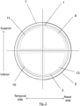
- the visual fields of the eye can be divided into quadrants, as shown in Fig. 2 , and these quadrants can also be used to describe the quadrants of a contact lens when positioned on an eye.
- the upper half of the eye/lens is the superior half 1, and the lower half is the inferior half 3.
- the visual field that is closest to the nose is the nasal half 5, and the visual field that is furthest from the nose is the temporal half 7.
- Four quadrants can therefore be defined as superior-nasal 9, superior-temporal 11, inferior-nasal 13 and inferior-temporal 15. In the description below, these definitions will be used to describe the position of the add power region and the variation in thickness of the peripheral region as they would be when the lens is in normal use and is being worn by a wearer.
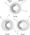
- Figs. 3(a)-(c) shows a lens 17 according to an embodiment of the present disclosure, having a treatment zone 19 that spans approximately half of the annular region (the temporal half).
- the iris 21 is shown schematically as it would be viewed through the cornea.
- the contrast-reducing characteristic of the treatment zone 19 will impact light that is being imaged from the wearer's right visual field, but, as shown in Fig. 4(c), the contrast-reducing characteristic of the treatment zone 19 will not impact light that is being imaged from the wearer's left visual field.
- Light from the wearer's left visual field that has passed through the treatment zone 19 will be blocked by the iris 21.
- the treatment zone 19 will significantly reduce image contrast for the left retina (nasal retina of the right eye, temporal retina of the left eye), but not for the right retina (temporal retina of the right eye, nasal retina of the left eye).
- the lens would significantly reduce image contrast for the right (temporal) retina, but not for the left (nasal) retina.
- contrast attenuation can be targeted at a peripheral retinal region whilst minimally disrupting foveal vision.
- the variation in thickness of the peripheral zone may be symmetric about a lens diameter, wherein the lens diameter divides the annular region into two halves, and wherein the treatment zone is confined to one half of the annular region.
- the variation in thickness may be substantially confined to lie along a lens diameter.
- the variation in thickness of the peripheral zone may be used to control the position of the treatment zone relative to the wearer's retina when the lens is worn by a wearer.
- the variation in thickness of the peripheral zone may comprise a ballast, and the ballast may control the rotation of the lens.
- the lens When the lens is in use, the lens may rotate such that the ballast is at or towards the bottom of the lens, i.e. in the inferior half.
- the lens may rotate such that the ballast is symmetric about the line dividing the temporal and nasal halves of the lens.
- the lens diameter may lie along the line separating the nasal and temporal halves of the lens.
- each lens in a set of lenses the treatment zone contrast reduction variation is rotationally positioned, relative to the peripheral zone thickness profile, at a different angle about the optic axis in each lens in the set of lenses.
- each lens in the set of lenses may have a treatment zone that spans approximately 25% of the area of the annular region.
- a first lens in the set of lenses may have a treatment zone that spans the inferior-temporal quadrant of the lens
- a second lens in the set of lenses may have a treatment zone that spans the superior-temporal quadrant of the lens
- a third lens in the set of lenses may have a treatment zone that spans the superior-nasal quadrant of the lens
- a fourth lens in the set of lenses may have a treatment zone that spans the inferior-nasal quadrant of the lens.
- Each set of lenses may comprise 2 lenses, for example, which may be intended to be worn on consecutive days.
- the set of lenses may comprise 7 lenses, for example, which may be intended to be worn on consecutive days of the week.
- each lens in the set of lenses has a treatment zone that is rotationally positioned, relative to the peripheral zone thickness profile, at a different angle about the optic axis, when each lens in the set of lenses is worn by a wearer the treatment zone will target a different region of the retina. Therefore, wearing each lens in the set of lenses in succession may reduce the ability of the eye to compensate for the contrast reducing effects of the treatment zone.
- the first optic axis of the centre region may lie along the centreline of the lens.
- the central region may focus light from a distant point object, on the first optical axis, to a spot on the first optical axis at a distal focal surface.
- the term surface does not refer to a physical surface, but to a surface that could be drawn through points where light from distant objects would be focused. Such a surface is also referred to as an image plane (even though it can be a curved surface) or image shell.
- the eye focuses light onto the retina, which is curved, and in a perfectly focused eye, the curvature of the image shell would match the curvature of the retina. Therefore, the eye does not focus light onto a flat mathematical plane.
- the curved surface of the retina is commonly referred to locally as a plane.
- the treatment zone may be provided over a continuous portion of the annular region of each lens.
- the treatment zone may span less than 50% of the area of the annular region of each lens.
- the treatment zone may span less than 25% of the annular region of each lens.
- the treatment zone may span less than 10% of the annular region of each lens.
- a plurality of unconnected treatment zones may span the annular region of each lens.
- each lens includes a plurality of unconnected treatment zones
- the total area spanned by the unconnected treatment zones of each lens may be less than 50% of the area of the annular region.
- the total area spanned by the unconnected treatment zones of each lens may be less than 25% of the area of the annular region.
- the total area spanned by the unconnected treatment zones of each lens may be less than 10% of the area of the annular region.
- Each unconnected treatment zone may span between 5% and 10% of the circumference of the annular region.
- each of the unconnected treatment zones may be approximately equal in area.
- the unconnected treatment zones may be spaced at regular intervals around the circumference of the annular region, or at irregular intervals around the circumference of the annular region.
- the unconnected portions may be separated by portions of the annular region that do not substantially reduce the contrast of an image of an object that is formed by light passing through the central region and the treatment zone compared to an image of an object that would be formed by light passing through only the central region.
- the portions between the treatment zones may have a curvature that provides the base power
- the treatment zone of each lens in a set of lenses may comprise a strong contrast reduction region having a characteristic that reduces the contrast of an image that is formed by light passing through the central region and the treatment zone compared to an image of an object that would be formed by light passing through only the central region by 50% or more.
- the strong contrast reduction region may reduce the contrast of the image formed by the lens by 75% of more.
- the treatment zone may further comprise a weaker contrast reducing zone that reduces the contrast of an image that is formed by light passing through the central region and the treatment zone compared to an image of an object that would be formed by light passing through only the central region by less than 50%.
- each lens in the set of lenses comprises a plurality of treatment zones
- any or all of the treatment zones may be strong contrast reducing zones.
- Any or all of the treatment zones may be weaker contrasting reducing zones.
- the treatment zone of each lens may have a curvature variation that provides an add power.
- the anterior surface of the treatment zone may have a smaller radius of curvature than the radius of curvature of the anterior surface of the central region and the remainder of the annular region.
- the treatment zone may therefore have a greater power than the base power of the central region and the remainder of the annular region.
- the focal point of the treatment zone may lie on a proximal focal surface, and the focal point for the central region and the remainder of the annular region may lie on a distal focal surface, which is further away from the posterior surface of the lens.
- the focal point treatment zone and the focal point of the central region may share a common optical axis. For a point source at infinity, light rays focused by the central region and the annular region form a focused image at the distal focal surface. Light rays focused by the central region also produce an unfocused blur spot at the proximal focal surface.
- At least some of the add power may be provided by curvature that is centred on a centre of curvature that is a first distance from the first optical axis.
- Light rays from a distant point source that pass through the treatment zone may be focused away from the first optical axis an add power focal surface.
- Light rays that pass through the central region may form an on-axis blur circle (or ellipse for toric lenses) at the max add power focal surface.
- Light rays from a distant point source that pass through the treatment zone may be focused outside the blur circle or ellipse.
- the central region of the lens has the base power. If the treatment zone comprises an add power region, the net near power of the treatment zone will be is the sum of the base power and the add power.
- the centre of curvature of the add power region may be a first distance from the first optical axis.
- the at least one add power region may be configured to generate a light distribution at a focal plane of the add power region that generally replicates any zonal geometry of the add power region.
- the focal plane of the add power region is defined by a plane that passes through the point at which light that passes through the add power region is focused.
- a focused arc may be generated at the focal plane of the add power region.
- the curvature of the treatment portion can be selected so as to position light that is focused at a treatment portion focal plane at a distance of between about 2 micrometres and about 700 micrometres from and normal to the optic axis, preferably between about 20 micrometres and about 300 micrometres.
- the treatment zone of the annular region has a width, and a normal to a surface of the treatment zone taken halfway across the width of the treatment zone region may cross a normal, taken at the centre of the central region, at the centre of the curvature of a surface of the central region.
- the treatment zone may thereby focus light from each distant point object to form a focused arc at a proximal focal surface, the arc being outside of and surrounding the blur circle formed by the light focused by the central region.
- the surface of the treatment zone may be an anterior surface.
- the surface of the central zone may be an anterior surface.
- the surface of the treatment zone may be the surface that has a curvature providing an add power.
- the surface of the central zone may be the surface that has a curvature providing the base power.
- the base power of the lens may be positive, and the treatment zone may have a power that is more positive than the base power.
- the max add power focal surface will be closer to the lens than the distal focal surface.
- An on-axis image will not be formed by light passing through the treatment zone.
- a wearer of the lens will therefore need to use the natural accommodation of their eye to bring nearby objects into focus. It may be that the light rays focused by the treatment do not intersect with the first optical axis of the contact lens at all, or not until after they have passed the add power focal surface.
- the base power of the lens may be negative, and the treatment zone may have a power that is less negative than the power of the base region, or the treatment zone may have a positive power. Considering the lens positioned on the cornea, if the power of the treatment zone is less negative than the base power, an add power focal surface will be more anterior in the eye than the distal focal surface.
- an add power focal surface will be on the opposite (image) side of the lens than the distal focal surface (which will be a virtual focal surface on the object side of the lens for negative base powers); if the power of the treatment zone is negative (but less negative than the base power), a virtual add power focal surface will be further from the lens than a virtual distal focal surface.
- each lens in a set of lenses has a treatment zone add power that is rotationally positioned, relative to the peripheral zone thickness profile, at a different angle about the optic axis
- each lens in the set will target add power towards a different region of the peripheral retina. Therefore, if the lenses are worn by the wearer at different times, add power will be targeted at different regions of the retina at different times. This is beneficial, particularly for hydrogel and silicone hydrogel lenses, as it is believed that over time, the eye may adapt to the blur at the add power focal surface, thereby reducing the effectiveness of an add power treatment zone preventing the worsening of myopia.
- the lenses may reduce the ability of the eye to compensate for blur over time.
- different parts of the retina will be exposed to different amounts of defocus, and this may be more effective in slowing the growth of myopia than wearing a single lens that provides a constant myopic defocus.
- each of the treatment zones of a given lens may have a curvature providing the same add power, or each of the treatment zones of a given lens may have curvatures that provide different add powers.
- the treatment zone of each lens may have an asymmetric power profile.
- a curvature providing an add power may be a curvature of the anterior surface of the lens.
- a curvature providing an add power may be a curvature of the posterior surface of the lens.
- a curvature providing an add power may be a curvature of the anterior surface and the posterior surface of the lens providing a combined effect.
- the base power will be negative or close to zero, and the central region will correct for distance vision.
- the base power may be between 0.5 diopters (D) and -20.0 diopters.
- the base power may be from -0.25 D to -20.0 D.
- Add power is defined as the difference between the base power and the power of the add power meridian.
- an add power provided by each treatment zone may between +0.5 and +10.0 D, preferably between +2.0 and +3.0 D.
- the power any add power regions will be more positive than the base power and similarly.
- the power of each of any add power regions may be less negative than the base power, or the power of any add power regions may be a positive power.
- the net power of the annular region in any add power region will be the sum of the base power and the add power.
- the treatment zone of each lens may include a feature that increases scattering of light passing through the treatment zone compared to light passing through only the central region.
- the feature may be disposed on an anterior surface of the annular region.
- the treatment zone of each lens may comprise optical elements burned into a surface of the lens, or etched into the surface of the lens.
- the treatment zone may have a curvature providing an add power wherein the centre of curvature is on the first optical axis.
- the treatment zone may include a characteristic that causes diffraction of light passing through the treatment zone.
- the treatment zone may include other characteristics that reduce the contrast of an image formed by light passing through the treatment zone and the central region, compared to an image that would be formed by light passing through only the central region.
- the annular region of each lens may have a substantially circular outer circumference.
- the annular region of each lens may have a substantially elliptical outer circumference.
- the central region of each lens may be substantially circular in shape and may have a diameter of between about 2 and 7 mm, preferably between 2 and 5 mm.
- the central region may be substantially elliptical in shape.
- the base curve may have a radius of curvature of between about 8.0 mm and 9.0 mm.
- the annular region of each lens may extend radially outwards from a perimeter of the central region by between 0.1 mm and about 4 mm, preferably by between 0.5 and 1.5 mm.
- the perimeter of the central region of each lens may define a boundary between the central region and the annular region, and the annular region may therefore be adjacent to the central region.
- each lens may abut the central region.
- a blending region may be provided between the central region and the annular region.
- the blending region should not substantially affect the optics provided by the central region and the annular region, and the blending region may have a radial width of 0.05 mm or less, although it may also be as wide as 0.2 mm, or as wide as 0.5 mm in some embodiments.
- the annular region may extend radially outwards to abut the peripheral zone.
- the treatment zone may span the radial width of the annular zone.
- Each lens in a set of lenses may include a plurality of concentric annular regions.
- Each annular region may be an annular region including a treatment zone having the characteristics outlined above.
- each lens has a base power, which in the context of the present disclosure, is defined as the average absolute refractive power of the central region. Any base power meridians will also have the base power.
- the base power will correspond to the labelled refractive power of the contact lens as provided on the contact lens packaging (though in practice it may not have the same value).
- the lens powers given herein are nominal powers. These values may differ from lens power values obtained by direct measurement of the lens, and are reflective of the lens powers that are used to provide a required prescription power when used in ophthalmic treatment.
- Each lens may comprise an elastomer material, a silicone elastomer material, a hydrogel material, or a silicone hydrogel material, or mixtures thereof.
- a hydrogel is a material that retains water in an equilibrium state and is free of a silicone-containing chemical.
- a silicone hydrogel is a hydrogel that includes a silicone-containing chemical.
- Hydrogel materials and silicone hydrogel materials as described in the context of the present disclosure, have an equilibrium water content (EWC) of at least 10% to about 90% (wt/wt). In some embodiments, the hydrogel material or silicone hydrogel material has an EWC from about 30% to about 70% (wt/wt).
- a silicone elastomer material as described in the context of the present disclosure, has a water content from about 0% to less than 10% (wt/wt).
- the silicone elastomer materials used with the present methods or apparatus have a water content from 0.1% to 3% (wt/wt).
- suitable lens formulations include those having the following United States Adopted Names (USANs): methafilcon A, ocufilcon A, ocufilcon B, ocufilcon C, ocufilcon D, omafilcon A, omafilcon B, comfilcon A, enfilcon A, stenfilcon A, fanfilcon A, etafilcon A, senofilcon A, senofilcon B, senofilcon C, narafilcon A, narafilcon B, balafilcon A, samfilcon A, lotrafilcon A, lotrafilcon B, somofilcon A, riofilcon A, delefilcon A, verofilcon A, kalifilcon A, and the like.
- each lens may comprise, consist essentially of, or consist of a silicone elastomer material.
- the lens may comprise, consist essentially of, or consist of a silicone elastomer material having a Shore A hardness from 3 to 50.
- the shore A hardness can be determined using conventional methods, as understood by persons of ordinary skill in the art (for example, using a method DIN 53505).
- Other silicone elastomer materials can be obtained from NuSil Technology or Dow Chemical Company, for example.
- the kit may comprise packaging for supplying the sets of contact lenses to a user.
- the kit may comprise written instructions for indicating an ordering sequence for wearing the lenses.
- Each lens in a set may be individually packaged, for example, in blister packaging.
- the packaging may, for example, comprise a strip of connected blister packets.
- Each set of lenses may be a set of two lenses, for use on consecutive days.
- Each set of lenses may be a set of 7 lenses, for use on consecutive days of each week.
- the instructions may instruct the wearer to wear a different lens every day, or after a certain number of hours or days.
- the written instructions may be provided on the packaging or on the lenses.
- Each lens in the first set of lenses has a treatment zone that is rotationally positioned, relative to the peripheral zone thickness profile, at a first angle about the first optical axis.
- For each lens in the first set of lenses there is a corresponding lens in the second set of lenses that has a treatment zone that is positioned relative to the peripheral zone thickness profile, at an equal and opposite angle about the first optical axis.
- the first set of lenses is a set of lenses for the left eye of a wearer
- the second set of lenses is a set of lenses for the right eye of a wearer, or vice versa.
- the present disclosure provides a method of manufacturing a first set of contact lens and a second set of contact lenses for use in a kit.
- the method comprises, in step (a) forming a first contact lens for a first set of contact lenses.
- the lens includes an optic zone and a peripheral zone surrounding the optic zone, the peripheral zone of each lens having a varying thickness profile that is configured to control rotation of the lens.
- the optic zone of each lens comprises_a central region, the central region having a first optical axis and a curvature providing a base power.
- the optic zone of each lens comprises an annular region. The annular region circumferentially surrounds the central region.
- the annular region comprises a treatment zone having a characteristic that reduces the contrast of an image that is formed by light passing through the central region and the treatment zone compared to an image of an object that would be formed by light passing through only the central region.
- the treatment zone of each lens comprising at least one of_(i) an add power region having a curvature providing an add power, wherein light from each distant point object is focused by a treatment zone to form a focused arc at a proximal focal surface, the arc being outside of and extending in a direction around a blur circle formed by the light focused by the central region; (ii) a feature that increases scattering of light passing through the treatment zone compared to light passing through only the central region; and_(iii) a characteristic that causes diffraction of light passing through the treatment zone.
- the method comprises, in step (b), repeating step (a) to form a second contact lens in the first set, wherein the treatment zone is rotationally positioned, relative to the peripheral zone thickness profile, at a different angle about the optic axis in the first lens and the second lens.
- the method comprises, in step (c), repeating steps (a) and (b) to form a second set of contact lenses.
- the second set of contact lenses has the features of the first set of lenses.
- the first set of contact lenses are a set of lenses for the left eye of a wearer, and the second set of lenses are a set of lenses for the right eye of the wearer, or vice versa.
- the second lens, and any subsequent lenses may have the same peripheral zone thickness profile as the first lens, and the same treatment zone contrast reduction variation as the first lens.
- Each lens in a set of lenses, and each set of lenses may include any of the features set out above.
- the method of manufacturing may comprise forming a female mold member with a concave lens forming surface and a male mold member with a convex lens forming surface.
- the method may comprise filling a gap between the female and male mold members with bulk lens material.
- the method may further comprise curing the bulk lens material to forms the lens.
- the contact lenses may be a formed using a lathing process.
- the lenses can be formed by cast molding processes, spin cast molding processes, or lathing processes, or a combination thereof.
- cast molding refers to the molding of a lens by placing a lens forming material between a female mold member having a concave lens member forming surface, and a male mold member having a convex lens member forming surface.
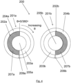
- Fig. 4 shows a set of contact lenses 200 for use in slowing progression of myopia (e.g. myopia control), for use in a kit according to an embodiment of the present disclosure.
- the set comprises two lenses 201a, 201b.
- Each lens 201a, 201b comprises an optic zone 202a, 202b, which approximately covers the pupil, and a peripheral zone 204a, 204b that sits over the iris.
- the peripheral zones 204a, 204b provide mechanical functions, including increasing the size of the lenses 201a, 201b thereby making the lenses 201a, 201b easier to handle, and providing a shaped region that improves comfort for the lens wearer.
- the peripheral zones 204a, 204b increase in thickness towards the bottom of the lens to provide ballasts 209a, 209b.
- the location of the thickest parts of the ballasting are indicated by triangles; however, the skilled person will appreciate that the variation in thickness may be provided by different types of ballasting or other thickness variations (see paragraph [0038] for examples).
- the variation in thickness of the peripheral zone 204a, 204b is the same.
- the ballasts 209a, 209b are positioned at the bottom of the lens (i.e.
- the ballasts 209a, 209b control the rotation of the lenses 201a, 201b, such that when the lenses 201a, 201b are being worn, they remain in a stable position in spite of rotational forces from the wearer blinking.
- the optic zones 202a, 202b provide the optical functionality of the lenses 201a, 201b.
- Each optic zone 202a, 202b comprises an annular region 203a, 203b and a central region 205a, 205b.
- Each annular region 203a, 203b comprises a treatment zone 207a, 207b that reduces the contrast of an image of an object that is formed by light passing through the central region 205a, 205b and the treatment zone 207a, 207b compared to an image of an object that would be formed by light passing through only the central region 205a, 205b.
- the first lens 201a has a treatment zone 207a that spans the temporal half of the lens 201a
- the second lens 201b has a treatment zone 201b that spans the nasal half of the lens 201a.
- the position around the circumference of the lens can be defined by an angle ⁇ , where ⁇ varies between 0° and 360°, as shown in Fig. 4 .
- the treatment zones 207a, 207b are rotationally positioned, relative to the ballasts 209a, 209b, at a different angles about the optic axis, with the treatment zone 207a of the first lens 201a spanning approximately 0-180° and the treatment zone 207b of the second lens spanning approximately 180-360°. If a wearer wears the two lenses 201a, 201b on successive days, the treatment zones 207a, 207b will target different regions of the retina at different times. This may reduce the ability of the eye to compensate for the contrast reducing effects of the treatment zone.
- the treatment zone has a curvature variation that provides an add power.
- Fig. 5 shows a cross section through the lens 201a of Fig. 4 .
- the anterior surface of the treatment zone 207a has a smaller radius of curvature than the radius of curvature of the anterior surface of the central region 205a and the remainder of the annular region 203a.
- the treatment zone 207a therefore has a greater power than the base power of the central region 205a and the remainder of the annular region 203a.
- the focal point of the treatment zone 207a lies on a proximal focal surface 222 (as indicated by the dashed line), and the focal point for the central region 205a and the remainder of the annular region 203a lies on a distal focal surface 224, which is further away from the posterior surface of the lens 201a.
- the focal point treatment zone 207a and the focal point of the central region 205a share a common optical axis 218.
- For a point source at infinity, light rays focused by the central region 205a and the annular region 203a form a focused image at the distal focal surface 224.
- Light rays focused by the central region 205a also produce an unfocused blur spot at the proximal focal surface 222.
- Fig. 6 shows a set of contact lenses 300 for use in slowing progression of myopia (e.g. myopia control), for use in a kit according to an embodiment of the present disclosure.
- the set comprises seven lenses 301a-g.
- each lens 301a-g comprises an optic zone 302a-g, which approximately covers the pupil, and a peripheral zone 304a-g that sits over the iris.
- the peripheral zones 304a-g provide mechanical functions, including increasing the size of the lenses 301a-g thereby making the lenses 301a-g easier to handle, and providing a shaped region that improves comfort for the lens wearer.
- the peripheral zones 304a-g have a variation in thickness provided by ballasts 309a-g.
- the variation in thickness of the peripheral zone is the same.
- the ballasts 309a-g are positioned at the bottom of the lens (i.e. in the inferior half), along the diameter that separates the temporal and nasal halves of the lens 301a-g.
- the ballasts 309a-g control the rotation of the lenses 301a-g, such that when the lenses 301a-g are being worn, they remain in a stable position in spite of rotational forces from the wearer blinking.
- the optic zones 302a-g provide the optical functionality of the lenses 301a-g.
- Each of the optic zones 302a-g comprises an annular region 303a-g and a central region 305a-g.
- Each annular region 302a-g comprises a treatment zone 307a-g that reduces the contrast of an image of an object that is formed by light passing through the central region 305a-g and the treatment zone 307a-g compared to an image of an object that would be formed by light passing through only the central region 305a-g.
- the first lens 301a has a treatment zone 307a that spans approximately 0-50° around the annular region 303a
- the second lens 301b has a treatment zone 107a that spans approximately 50-100°.
- Each lens 301a-g in the set has a treatment zone 307a-g that spans a different sector of the annular region 303a-g relative to the ballast 309a-g. If a wearer wears the lenses 301a-g on successive days, the treatment zones 307a-g will target different regions of the retina at different times.
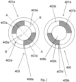
- Fig. 7 shows a set of contact lenses 400 for use in slowing progression of myopia (e.g. myopia control), for use in a kit according to an embodiment of the present disclosure.
- the set comprises two lenses 401a, 401b.
- each lens 401a, 401b comprises an optic zone 402a, 402b, which approximately covers the pupil, and a peripheral zone 404a, 404b that sits over the iris.
- the peripheral zones 404a, 404b provide mechanical functions, including increasing the size of the lenses 401, 401b thereby making the lenses 401, 401b easier to handle, and providing a shaped region that improves comfort for the lens wearer.
- the peripheral zones 404a, 404b have a variation in thickness provided by ballasts 409a, 409b.
- the variation in thickness of the peripheral zone 404a, 404b is the same.
- the ballasts 409a, 409b are positioned at the bottom of the lens 401a, 401b (i.e. in the inferior half), along the diameter that separates the temporal and nasal halves of the lens 401a, 401b.
- the ballasts 409a, 409b control the rotation of the lenses 401a, 401b, such that when the lenses 401a, 401b are being worn, they remain in a stable position in spite of rotational forces from the wearer blinking.
- the optic zones 402a, 402b provide the optical functionality of the lenses 401a, 401b.
- Each of the optic zones 402a, 402b comprises an annular region 403a, 403b and a central region 405a, 405b.
- Each annular region 403a, 403b comprises two treatment zones 407a, 407b, 407a', 407b' that reduces the contrast of an image of an object that is formed by light passing through the central region 405a, 405b and the treatment zone 407a, 407b, 407a', 407b'compared to an image of an object that would be formed by light passing through only the central region 405a, 405b.
- the first lens 401a has a first treatment zone 407a that spans the superior-temporal quadrant, or 270-360 ° around the annular region 403a, and a second treatment zone 407a' that spans the inferior-nasal quadrant, or 90-180° around the annular region 403a.
- the second lens 401b has a first treatment zone 407b that spans the superior-nasal quadrant, or 0-90° around the annular region 403b and a second treatment zone 407b' that spans the inferior-temporal quadrant, or 180-270° around the annular region 403b.
- Each lens 401a, 401b in the set 400 has 2 treatment zones 407a, 407b, 407a', 407b', and the treatment zones of each lens span different segments of the annular region 403a, 403b relative to the ballast 409a, 409b. If a wearer wears the lenses 401a, 401b on successive days, the treatment zones 407a, 407b, 407a', 407b' will target different regions of the retina at different times.
- each treatment zone 407a, 407b, 407a', 407b' has a curvature that provides an add power.
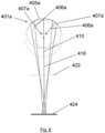
- the central region 405a, 405b has a curvature providing a base power and centred on a centre of curvature that is on the first optical axis 418. This is shown in Fig. 8 which is a schematic of a cross section through the first lens 407a in the set taken along the line A-A.
- Each treatment zone 407a, 407a' has a curvature that provides an add power.
- the radius of curvature 406a of the anterior surface of the treatment zones 407a, 407a' (indicated by the dashed circles) is smaller than the radius of curvature 410 of the anterior surface of the central region 405a (indicated by the dot-dash circle).
- the treatment zones 407a, 407a' therefore have a greater power than the base power of the central region 405.
- Each of the treatment zones 407a, 407a' has the same anterior curvature and the same power. As shown in Fig.
- the focal point of the treatment zones 407a, 407a' lies on a proximal focal surface 422, and the focal point for the central region 405a lies on a distal focal surface 424, which is further away from the posterior surface of the lens 401a.
- the focal point 425 of the treatment zones 407a, 407a' and the focal point 424 of the central region 405a share a common optical axis 418.
- light rays focused by the central region 405a form a focused image at the distal focal surface 424.
- Light rays focused by the central region 405a also produce an unfocused blur spot at the proximal focal surface 422.
- Light rays focused by the treatment zones 407a, 407a' form a focused image at the proximal focal surface 422.
- Light rays 420 focused by the treatment zones 407a, 407a' diverge after the proximal focal surface 422.
- the add power treatment zones 407a, 407a' reduce the contrast of an image of an object that is formed by light passing through the central region and the treatment zone compared to an image of an object that would be formed by light passing through only the central region 405.
- these regions In between the treatment zones 407a, 407a' there are regions that do not significantly reduce the contrast of an image formed by light passing through the lens 401.
- these regions For the lens 401a of Fig. 7 , these regions have the base power, and as shown in Fig. 9 , which shows a cross section through the lens 401a taken along the line B-B, light passing through these regions will be focused at the distal focal surface 424.
- the second lens 401b in the set 400 has treatment zones 407b, 407b' spanning opposite quadrants. Therefore if the wearer wears the two lenses 401a, 401a' on successive days, on the first day, the treatment zones 407a, 407a' of the first les 401a will target add power at a first two quadrants (in this case, the inferior-nasal and superior-temporal quadrants) and on the second day, the treatment zones 407b, 407b' of the second lens 401b will target add power at a second, different two quadrants (in this case, the inferior-temporal and superior-nasal quadrants).
- a first two quadrants in this case, the inferior-nasal and superior-temporal quadrants
- the 2 treatment zones of each lens have the same power. In other embodiments, the 2 treatment zones may have different powers.
- Fig. 10 shows a set of contact lenses 500 for use in slowing progression of myopia (e.g. myopia control), for use in a kit according to an embodiment of the present disclosure.
- the set 500 comprises four lenses 501a-d.
- Each lens 501a-d comprises an optic zone 502a-d, which approximately covers the pupil, and a peripheral zone 504a-d that sits over the iris.
- the peripheral zones 504a-d provide mechanical functions, including increasing the size of the lenses 401a-d thereby making the lenses 501a-d easier to handle, and providing a shaped region that improves comfort for the lens wearer.
- the peripheral zones 504a-d have a variation in thickness provided by ballasts 509a-d.
- the ballasts 509a-d are positioned at the bottom of the lens 501a-d (i.e. in the inferior half), along the diameter that separates the temporal and nasal halves of the lens 501a-d.
- the ballasts 509a-d control the rotation of the lenses 501a-d such that when the lenses 501a-d are being worn, they remain in a stable position in spite of rotational forces from the wearer blinking.
- the optic zones 502a-d provide the optical functionality of the lenses 501a-d.
- Each of the optic zones 502a-d comprises an annular region 503a-d and a central region 505a-d.
- Each annular region 503a-d comprises a treatment zone 507a-d that that reduces the contrast of an image that is formed by light passing through the central region 505a-d and the treatment zone 507a-d compared to an image of an object that would be formed by light passing through only the central region 505a.
- the contrast reduction varies with meridian around the annular region 503a-d.
- the first lens 501a has a first treatment zone 507a that spans the superior-temporal quadrant, or 270-360 ° around the annular region 503a
- the second lens 501b has a second treatment zone 507b that spans the superior-nasal quadrant or 0-90° around the annular region 503b
- the third lens 501c has a treatment zone 507c that spans the inferior-nasal quadrant or 90-180° around the annular region 503c
- the fourth lens 501d has a treatment zone 507d that spans the inferior-temporal quadrant or 180-270° around the annular region.
- Each lens 501a-d in the set therefore has treatment zones 507a-d that spans a different segment of the annular region 503a-d relative to the ballast 509a-d. If a wearer wears the lenses 501a-d on successive days, the treatment zones 507a-d will target different regions of the retina.
- each treatment zone 507a-d has a curvature that provides an add power.
- the central region 505 has a curvature providing a base power and centred on a centre of curvature that is on the first optical axis.
- Each treatment zone 507a-d has a curvature that provides an add power.
- the radius of curvature of the anterior surface of the treatment zones 507a-d is smaller than the radius of curvature of the anterior surface of the central region 505a-d.
- the treatment zones 507a-d therefore have a greater power than the base power of the central region 505a-d.
- Each of the treatment zones 507a-d has the same anterior curvature and the same power, and each of the treatment zones has an asymmetric anterior surface curvature, which gives rise to an asymmetric power profile. Examples asymmetric power profiles are shown for each of the lenses in the set 500 in Figure 11(a)-(d) .
- the treatment zone 507b-d is rotated by 90° around the annular region 503(a)-(d).
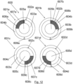
- Fig. 12 shows a set of contact lenses 600 for use in slowing progression of myopia (e.g. myopia control), for use in a kit according to an embodiment of the present disclosure.
- This set 600 is similar to the set of lenses shown in Fig. 10 .
- each of the treatment zones 607a-d comprises features 608a-d that increases scattering of light passing through the treatment zones 607a-d compared to light passing through the remainder of the annular regions 603a-d and the central regions 605a-d.
- light scattering features are provided in treatment zones that span a single quadrant of the annular region of each lens. It will be appreciated that such features could be provided in lenses having any other configurations of treatment zones falling within the scope of the claims.
- each lens in the lens set may be provided with two concentric annular regions, and each annular region may be an annular region including a treatment zone, as described above.
- the treatment zone may comprise a characteristic that reduces contrast of light of an image that is formed by light passing through the central region and the treatment zone compared to an image of an object that would be formed by light passing through only the central region by causing diffraction effects.
Landscapes
- Health & Medical Sciences (AREA)
- Ophthalmology & Optometry (AREA)
- Physics & Mathematics (AREA)
- General Physics & Mathematics (AREA)
- Optics & Photonics (AREA)
- General Health & Medical Sciences (AREA)
- Engineering & Computer Science (AREA)
- Manufacturing & Machinery (AREA)
- Mechanical Engineering (AREA)
- Eyeglasses (AREA)
- Rehabilitation Tools (AREA)
Claims (17)
- Kit zur Verwendung zur Verhinderung oder Verlangsamung der Entwicklung oder des Fortschreitens von Myopie, wobei der Kit Folgendes umfasst:ein erstes Set (200) von Kontaktlinsen, wobei jede Linse (201a, 201b) im ersten Set von Linsen (200) eine optische Zone (202a, 202b) und eine periphere Zone (204a, 204b) aufweist, die die optische Zone (202a, 202b) umgibt, wobei die periphere Zone (204a, 204b) jeder Linse (201a, 201b) ein variierendes Dickenprofil aufweist, das so konfiguriert ist, dass es die Rotation der Linse (201a, 201b) steuert, und wobei die optische Zone (202a, 202b) jeder Linse (201a, 201b) umfasst:einen zentralen Bereich (205a, 205b), wobei der zentrale Bereich (205a, 205b) eine erste optische Achse und eine Krümmung aufweist, die eine Basisstärke liefert;einen ringförmigen Bereich (203a, 203b), wobei der ringförmige Bereich (203a, 203b) den zentralen Bereich (205a, 205b) in Umfangsrichtung umgibt, und wobei der ringförmige Bereich (203a, 203b) eine Behandlungszone (207a, 207b) umfasst, die eine Eigenschaft aufweist, die den Kontrast eines Bildes, das durch Licht gebildet wird, das durch den zentralen Bereich (205a, 205b) und die Behandlungszone (207a, 207b) hindurchgeht, im Vergleich zu einem Bild eines Objekts verringert, das durch Licht gebildet wird, das nur durch den zentralen Bereich (205a, 205b) hindurchgeht, wobei die Behandlungszone (207a, 207b) jeder Linse (201a, 201b) mindestens Folgendes umfasst:(a) einen Bereich mit Additionswert mit einer Krümmung, die einen Additionswert bereitstellt, wobei Licht von jedem entfernten Punktobjekt durch eine Behandlungszone (207a, 207b) fokussiert wird, um einen fokussierten Bogen an einer proximalen Brennfläche zu bilden, wobei der Bogen außerhalb eines Unschärfekreises liegt und sich in einer Richtung um ihn herum erstreckt, der durch das vom zentralen Bereich (205a, 205b) fokussierte Licht gebildet wird,(b) ein Merkmal, das die Streuung von Licht, das durch die Behandlungszone hindurchgeht, im Vergleich zu Licht, das nur durch den zentralen Bereich hindurchgeht, erhöht; und(c) eine Eigenschaft, die eine Diffraktion des Lichts verursacht, das durch die Behandlungszone hindurchgeht; wobeidie Behandlungszone in jeder Linse des Linsensets relativ zum Dickenprofil der peripheren Zone in einem anderen Winkel um die optische Achse drehbar angeordnet ist; undein zweites Set von Kontaktlinsen mit den Merkmalen des ersten Sets (200) der Linsen (201a, 201b), wobei für jede Linse (201a, 201b) im ersten Set (200) der Linsen (201a, 201b) mit einer Behandlungszone (207a, 207b), die relativ zum Dickenprofil der peripheren Zone (204a, 204b) in einem ersten Winkel um die optische Achse drehbar angeordnet ist, eine entsprechende Linse im zweiten Linsenset vorhanden ist, die eine Behandlungszone aufweist, die relativ zum Dickenprofil der peripheren Zone in einem gleichen und entgegengesetzten Winkel um die erste optische Achse angeordnet ist, und wobei das erste Set (200) der Kontaktlinsen ein Linsenset für das linke Auge eines Trägers ist, und das zweite Linsenset ein Linsenset für das rechte Auge des Trägers ist, oder umgekehrt.
- Kit nach Anspruch 1, wobei die Behandlungszone jeder Linse über einen kontinuierlichen Teil des ringförmigen Bereichs jeder Linse vorgesehen ist, und wobei sich die Behandlungszone über weniger als 50 % der Fläche des ringförmigen Bereichs jeder Linse erstreckt.
- Kit nach Anspruch 1 oder Anspruch 2, wobei sich eine Vielzahl von unverbundenen Behandlungszonen über den ringförmigen Bereich jeder Linse erstrecken.
- Kit nach einem der vorhergehenden Ansprüche, wobei die Behandlungszone jeder Linse einen Bereich mit starker Kontrastverringerung umfasst, der den Kontrast eines Bildes, das durch Licht gebildet wird, das durch den zentralen Bereich und die Behandlungszone hindurchgeht, im Vergleich zu einem Bild eines Objekts, das durch Licht gebildet würde, das nur durch den zentralen Bereich hindurchgeht, um 50% oder mehr verringert.
- Kit nach einem der vorhergehenden Ansprüche, wobei die Behandlungszone jeder Linse eine Krümmungsvariation aufweist, die einen Additionswert bereitstellt, und wobei in jeder Linse mindestens ein Teil der Additionsstärke durch eine Krümmung bereitgestellt wird, die auf einen Krümmungsmittelpunkt zentriert ist, der ein erster Abstand von der ersten optischen Achse ist.
- Kit nach Anspruch 5, wobei die Behandlungszone jeder Linse ein asymmetrisches Stärkeprofil aufweist.
- Kit nach einem der Ansprüche 5 bis 6, wobei für jede Linse die Krümmung, die den Additionswert bereitstellt, eine Krümmung der vorderen Oberfläche der Linse sein kann.
- Kit nach einem der Ansprüche 5 bis 7, wobei der von der Behandlungszone jeder Linse bereitgestellte Additionswert zwischen +0,5 und +10,0 D liegt.
- Kit nach einem der vorhergehenden Ansprüche, wobei die Behandlungszone jeder Linse ein Merkmal aufweisen kann, das die Streuung von Licht, das durch die Behandlungszone hindurchgeht, im Vergleich zu Licht, das nur durch den zentralen Bereich hindurchgeht, erhöht, und wobei das Merkmal auf einer vorderen Oberfläche des ringförmigen Bereichs angeordnet ist.
- Kit nach einem der vorhergehenden Ansprüche, wobei der ringförmige Bereich j eder Linse einen im Wesentlichen kreisförmigen Außenumfang oder einen im Wesentlichen elliptischen Außenumfang aufweist.
- Kit nach einem der vorhergehenden Ansprüche, wobei der zentrale Bereich jeder Linse im Wesentlichen kreisförmig ist und einen Durchmesser zwischen 2 und 7 mm hat.
- Kit nach einem der vorhergehenden Ansprüche, wobei sich der ringförmige Bereich jeder Linse von einem Umfang des zentralen Bereichs radial nach außen um zwischen 0,5 und 1,5 mm erstreckt.
- Kit nach einem der vorhergehenden Ansprüche, wobei jede Linse ein Elastomermaterial, ein Silikonelastomermaterial, ein Hydrogelmaterial oder ein Silikonhydrogelmaterial oder Mischungen daraus umfasst.
- Kit nach einem der vorhergehenden Ansprüche, wobei jede Linse durch ein Drehverfahren hergestellt wird.
- Kit nach einem der vorhergehenden Ansprüche, wobei das variierende Dickenprofil jeder peripheren Zone ein Prismenballast ist.
- Kit nach einem der vorhergehenden Ansprüche, der außerdem Folgendes umfasst:Verpackung zum Bereitstellen des Kontaktlinsensets für einen Benutzer, undschriftliche Anweisungen, die eine Reihenfolge für das Tragen der Linsen angeben, wobei optional die schriftlichen Anweisungen auf der Verpackung oder auf einer der Linsen angebracht sind.
- Verfahren zur Herstellung eines ersten Kontaktlinsensets und eines zweiten Kontaktlinsensets zur Verwendung in einem Kit nach einem der vorhergehenden Ansprüche, wobei das Verfahren umfasst:(a) Formen einer ersten Kontaktlinse für ein erstes Kontaktlinsenset, wobei die Linse eine optische Zone und eine periphere Zone, die die optische Zone umgibt, umfasst, wobei die periphere Zone jeder Linse ein variierendes Dickenprofil aufweist, das so konfiguriert ist, dass es die Rotation der Linse steuert, und wobei die optische Zone jeder Linse Folgendes umfasst:einen zentralen Bereich, wobei der zentrale Bereich eine erste optische Achse und eine Krümmung aufweist, die eine Basisstärke liefert;einen ringförmigen Bereich, wobei der ringförmige Bereich den zentralen Bereich in Umfangsrichtung umgibt, und wobei der ringförmige Bereich eine Behandlungszone mit einer Eigenschaft umfasst, die den Kontrast eines Bildes, das durch Licht, das durch den zentralen Bereich und die Behandlungszone hindurchgeht, erzeugt wird, im Vergleich zu einem Bild eines Objekts verringert, das durch Licht, das nur durch den zentralen Bereich hindurchgeht, erzeugt würde, wobei die Behandlungszone jeder Linse mindestens eines der folgenden Merkmale umfasst:(i) einen Bereich mit Additionsstärke mit einer Krümmung, die einen Additionswert bereitstellt, wobei Licht von jedem entfernten Punktobjekt durch eine Behandlungszone fokussiert wird, um einen fokussierten Bogen an einer proximalen Brennfläche zu bilden, wobei der Bogen außerhalb eines Unschärfekreises liegt und sich in einer Richtung um ihn herum erstreckt, der durch das vom zentralen Bereich fokussierte Licht gebildet wird; (ii) ein Merkmal, das die Streuung von Licht, das durch die Behandlungszone hindurchgeht, im Vergleich zu Licht, das nur durch den zentralen Bereich hindurchgeht, erhöht; und(iii) ein Merkmal, das eine Diffraktion des durch die Behandlungszone hindurchgehenden Lichts bewirkt;(b) Wiederholen von Schritt (a), um eine zweite Kontaktlinse im ersten Set zu bilden, wobei die Behandlungszone relativ zum Dickenprofil der peripheren Zone in der ersten Linse und der zweiten Linse in einem unterschiedlichen Winkel um die optische Achse drehbar angeordnet ist; und(c) Wiederholen der Schritte (a) und (b), um ein zweitens Kontaktlinsenset zu bilden, wobei das zweite Kontaktlinsenset die Merkmale des ersten Linsensets aufweist, wobei für jede Linse im ersten Linsenset, die eine Behandlungszone aufweist, die relativ zum Dickenprofil der peripheren Zone in einem ersten Winkel um die optische Achse drehbar angeordnet ist, eine entsprechende Linse im zweiten Linsenset vorhanden ist, die eine Behandlungszone aufweist, die relativ zum Dickenprofil der peripheren Zone in einem gleichen und entgegengesetzten Winkel um die erste optische Achse angeordnet ist, und wobei das erste Kontaktlinsenset ein Linsenset für das linke Auge eines Trägers ist, und das zweite Linsenset ein Linsenset für das rechte Auge des Trägers ist oder umgekehrt.
Priority Applications (1)
| Application Number | Priority Date | Filing Date | Title |
|---|---|---|---|
| EP24206393.1A EP4468068A3 (de) | 2021-04-29 | 2022-04-22 | Linsensätze zur verwendung bei der vorbeugung oder verlangsamung der entwicklung oder des fortschreitens von myopie und zugehörige verfahren |
Applications Claiming Priority (2)
| Application Number | Priority Date | Filing Date | Title |
|---|---|---|---|
| US202163181249P | 2021-04-29 | 2021-04-29 | |
| PCT/GB2022/051024 WO2022229608A1 (en) | 2021-04-29 | 2022-04-22 | Lens sets for use in preventing or slowing the development or progression of myopia and related methods |
Related Child Applications (2)
| Application Number | Title | Priority Date | Filing Date |
|---|---|---|---|
| EP24206393.1A Division EP4468068A3 (de) | 2021-04-29 | 2022-04-22 | Linsensätze zur verwendung bei der vorbeugung oder verlangsamung der entwicklung oder des fortschreitens von myopie und zugehörige verfahren |
| EP24206393.1A Division-Into EP4468068A3 (de) | 2021-04-29 | 2022-04-22 | Linsensätze zur verwendung bei der vorbeugung oder verlangsamung der entwicklung oder des fortschreitens von myopie und zugehörige verfahren |
Publications (3)
| Publication Number | Publication Date |
|---|---|
| EP4291944A1 EP4291944A1 (de) | 2023-12-20 |
| EP4291944B1 true EP4291944B1 (de) | 2024-10-30 |
| EP4291944B8 EP4291944B8 (de) | 2024-12-04 |
Family
ID=81581159
Family Applications (2)
| Application Number | Title | Priority Date | Filing Date |
|---|---|---|---|
| EP22721436.8A Active EP4291944B8 (de) | 2021-04-29 | 2022-04-22 | Linsensätze zur verwendung bei der vorbeugung oder verlangsamung der entwicklung oder des fortschreitens von myopie und zugehörige verfahren |
| EP24206393.1A Withdrawn EP4468068A3 (de) | 2021-04-29 | 2022-04-22 | Linsensätze zur verwendung bei der vorbeugung oder verlangsamung der entwicklung oder des fortschreitens von myopie und zugehörige verfahren |
Family Applications After (1)
| Application Number | Title | Priority Date | Filing Date |
|---|---|---|---|
| EP24206393.1A Withdrawn EP4468068A3 (de) | 2021-04-29 | 2022-04-22 | Linsensätze zur verwendung bei der vorbeugung oder verlangsamung der entwicklung oder des fortschreitens von myopie und zugehörige verfahren |
Country Status (14)
| Country | Link |
|---|---|
| US (1) | US20220350164A1 (de) |
| EP (2) | EP4291944B8 (de) |
| JP (2) | JP2024512548A (de) |
| KR (1) | KR102770623B1 (de) |
| CN (1) | CN117083561B (de) |
| AU (1) | AU2022267839B2 (de) |
| CA (1) | CA3210711C (de) |
| ES (1) | ES2998813T3 (de) |
| GB (1) | GB2607709B (de) |
| HU (1) | HUE070140T2 (de) |
| MX (1) | MX2023011140A (de) |
| MY (1) | MY204518A (de) |
| TW (1) | TWI874766B (de) |
| WO (1) | WO2022229608A1 (de) |
Families Citing this family (1)
| Publication number | Priority date | Publication date | Assignee | Title |
|---|---|---|---|---|
| GB2615863B (en) | 2021-12-21 | 2024-05-22 | Coopervision Int Ltd | Contact lenses and methods relating thereto |
Family Cites Families (24)
| Publication number | Priority date | Publication date | Assignee | Title |
|---|---|---|---|---|
| US20040141150A1 (en) * | 2003-01-21 | 2004-07-22 | Roffman Jeffrey H. | Hybrid multifocal contact lenses |
| AU2006301940B2 (en) * | 2005-10-12 | 2012-03-29 | Carl Zeiss Vision Australia Holdings Limited | Ophthalmic lens element for myopia correction |
| US8690319B2 (en) * | 2007-05-21 | 2014-04-08 | Johnson & Johnson Vision Care, Inc. | Ophthalmic lenses for prevention of myopia progression |
| US7625085B2 (en) * | 2007-08-07 | 2009-12-01 | Novartis Ag | Toric contact lens with improved posterior surface design |
| AU2011284783B2 (en) * | 2010-07-26 | 2014-07-31 | Vision Crc Limited | Treating ocular refractive error |
| JP6310072B2 (ja) * | 2013-06-26 | 2018-04-11 | ネクシスビジョン, インコーポレイテッド | 屈折矯正のためのコンタクトレンズ |
| US10031347B2 (en) * | 2014-01-31 | 2018-07-24 | Ophtec B.V. | Multifocal ophthalmic lens to be worn in or on the eye |
| WO2015132889A1 (ja) * | 2014-03-04 | 2015-09-11 | 株式会社メニコン | ディセンタタイプのコンタクトレンズおよびディセンタタイプのコンタクトレンズセット |
| JP6294466B2 (ja) * | 2014-03-31 | 2018-03-14 | ホヤ レンズ タイランド リミテッドHOYA Lens Thailand Ltd | 累進屈折力レンズの設計方法および製造方法、ならびに累進屈折力レンズ製造システム |
| US9638936B2 (en) * | 2014-08-20 | 2017-05-02 | Johnson & Johnson Vision Care, Inc. | High plus treatment zone lens design for preventing and/or slowing myopia progression |
| TW201629582A (zh) * | 2014-11-05 | 2016-08-16 | 布萊恩荷登視覺協會 | 有關用於抑制近視加深之單視及多焦點鏡片的系統及方法 |
| EP3625620B1 (de) * | 2017-05-08 | 2025-09-10 | SIGHTGLASS VISION, Inc. | Herstellungsverfahren von kontaktlinsen zur reduzierung von myopie |
| US10901237B2 (en) * | 2018-01-22 | 2021-01-26 | Johnson & Johnson Vision Care, Inc. | Ophthalmic lens with an optically non-coaxial zone for myopia control |
| US10884264B2 (en) * | 2018-01-30 | 2021-01-05 | Sightglass Vision, Inc. | Ophthalmic lenses with light scattering for treating myopia |
| WO2020072621A1 (en) * | 2018-10-02 | 2020-04-09 | Aldeyra Therapeutics, Inc. | Contact lens solutions and kits |
| CN208834031U (zh) * | 2018-10-24 | 2019-05-07 | 金张云 | 一种隐形渐进多焦点镜片 |
| CN114630640A (zh) * | 2019-07-19 | 2022-06-14 | 克莱里奥视觉股份有限公司 | 近视进展治疗 |
| CN119916591A (zh) * | 2019-08-23 | 2025-05-02 | 华柏恩视觉研究中心有限公司 | 用于减少、最小化和/或消除失焦光对聚焦图像的干扰的眼科镜片 |
| EP4034940A4 (de) * | 2019-09-25 | 2023-10-18 | Nthalmic Holding Pty Ltd | Vorrichtung und verfahren für brillenlösungen bei myopie |
| CN114667477B (zh) * | 2019-09-25 | 2025-01-10 | 恩视控股有限公司 | 用于近视管理的接触透镜解决方案 |
| EP4034939B1 (de) * | 2019-09-25 | 2026-04-08 | Nthalmic Holding Pty Ltd | Freiform-kontaktlinsenlösung für myopie |
| US11762220B2 (en) * | 2020-04-30 | 2023-09-19 | Coopervision International Limited | Multifocal ophthalmic lenses and related methods |
| WO2021231684A1 (en) * | 2020-05-13 | 2021-11-18 | Acucela Inc. | Electro-switchable spectacles for myopia treatment |
| TWI895449B (zh) * | 2020-06-26 | 2025-09-01 | 澳大利亞商布萊恩荷登視覺協會 | 具幾何定義形狀及/或輪廓光學元件之眼用鏡片 |
-
2022
- 2022-04-22 ES ES22721436T patent/ES2998813T3/es active Active
- 2022-04-22 KR KR1020237031666A patent/KR102770623B1/ko active Active
- 2022-04-22 WO PCT/GB2022/051024 patent/WO2022229608A1/en not_active Ceased
- 2022-04-22 JP JP2023558273A patent/JP2024512548A/ja active Pending
- 2022-04-22 HU HUE22721436A patent/HUE070140T2/hu unknown
- 2022-04-22 EP EP22721436.8A patent/EP4291944B8/de active Active
- 2022-04-22 EP EP24206393.1A patent/EP4468068A3/de not_active Withdrawn
- 2022-04-22 CN CN202280024891.7A patent/CN117083561B/zh active Active
- 2022-04-22 AU AU2022267839A patent/AU2022267839B2/en active Active
- 2022-04-22 GB GB2205862.2A patent/GB2607709B/en active Active
- 2022-04-22 CA CA3210711A patent/CA3210711C/en active Active
- 2022-04-22 MY MYPI2023005337A patent/MY204518A/en unknown
- 2022-04-22 MX MX2023011140A patent/MX2023011140A/es unknown
- 2022-04-27 US US17/730,240 patent/US20220350164A1/en active Pending
- 2022-04-27 TW TW111115949A patent/TWI874766B/zh active
-
2024
- 2024-12-06 JP JP2024213030A patent/JP2025060635A/ja active Pending
Also Published As
| Publication number | Publication date |
|---|---|
| TW202303230A (zh) | 2023-01-16 |
| AU2022267839A1 (en) | 2023-09-21 |
| GB202205862D0 (en) | 2022-06-08 |
| EP4291944A1 (de) | 2023-12-20 |
| EP4468068A3 (de) | 2025-01-29 |
| JP2025060635A (ja) | 2025-04-10 |
| EP4291944B8 (de) | 2024-12-04 |
| GB2607709B (en) | 2024-01-03 |
| EP4468068A2 (de) | 2024-11-27 |
| KR20230141879A (ko) | 2023-10-10 |
| TWI874766B (zh) | 2025-03-01 |
| MY204518A (en) | 2024-09-02 |
| CN117083561A (zh) | 2023-11-17 |
| JP2024512548A (ja) | 2024-03-19 |
| KR102770623B1 (ko) | 2025-02-24 |
| CA3210711A1 (en) | 2022-11-03 |
| MX2023011140A (es) | 2024-05-23 |
| WO2022229608A1 (en) | 2022-11-03 |
| CN117083561B (zh) | 2024-11-12 |
| US20220350164A1 (en) | 2022-11-03 |
| GB2607709A (en) | 2022-12-14 |
| CA3210711C (en) | 2024-05-28 |
| AU2022267839B2 (en) | 2024-02-15 |
| HUE070140T2 (hu) | 2025-05-28 |
| ES2998813T3 (en) | 2025-02-21 |
Similar Documents
| Publication | Publication Date | Title |
|---|---|---|
| AU2021404185B2 (en) | Myopia-control contact lenses and methods relating thereto | |
| AU2022267043B2 (en) | Contact lenses for use in preventing or slowing the development or progression of myopia and related methods | |
| AU2024227594A1 (en) | Methods of increased contact lens rotation | |
| US20230032140A1 (en) | Methods of increased contact lens rotation and related contact lenses | |
| EP4291944B1 (de) | Linsensätze zur verwendung bei der vorbeugung oder verlangsamung der entwicklung oder des fortschreitens von myopie und zugehörige verfahren | |
| US20230030700A1 (en) | Methods to avoid blur adaptation using myopia control contact lenses | |
| HK40095696B (zh) | 用於预防或减缓近视的发展或进展的镜片组及其相关方法 | |
| HK40095696A (zh) | 用於预防或减缓近视的发展或进展的镜片组及其相关方法 |
Legal Events
| Date | Code | Title | Description |
|---|---|---|---|
| STAA | Information on the status of an ep patent application or granted ep patent |
Free format text: STATUS: UNKNOWN |
|
| STAA | Information on the status of an ep patent application or granted ep patent |
Free format text: STATUS: THE INTERNATIONAL PUBLICATION HAS BEEN MADE |
|
| PUAI | Public reference made under article 153(3) epc to a published international application that has entered the european phase |
Free format text: ORIGINAL CODE: 0009012 |
|
| STAA | Information on the status of an ep patent application or granted ep patent |
Free format text: STATUS: REQUEST FOR EXAMINATION WAS MADE |
|
| 17P | Request for examination filed |
Effective date: 20230913 |
|
| AK | Designated contracting states |
Kind code of ref document: A1 Designated state(s): AL AT BE BG CH CY CZ DE DK EE ES FI FR GB GR HR HU IE IS IT LI LT LU LV MC MK MT NL NO PL PT RO RS SE SI SK SM TR |
|
| GRAP | Despatch of communication of intention to grant a patent |
Free format text: ORIGINAL CODE: EPIDOSNIGR1 |
|
| STAA | Information on the status of an ep patent application or granted ep patent |
Free format text: STATUS: GRANT OF PATENT IS INTENDED |
|
| INTG | Intention to grant announced |
Effective date: 20240208 |
|
| GRAJ | Information related to disapproval of communication of intention to grant by the applicant or resumption of examination proceedings by the epo deleted |
Free format text: ORIGINAL CODE: EPIDOSDIGR1 |
|
| STAA | Information on the status of an ep patent application or granted ep patent |
Free format text: STATUS: REQUEST FOR EXAMINATION WAS MADE |
|
| DAV | Request for validation of the european patent (deleted) | ||
| DAX | Request for extension of the european patent (deleted) | ||
| INTC | Intention to grant announced (deleted) | ||
| GRAP | Despatch of communication of intention to grant a patent |
Free format text: ORIGINAL CODE: EPIDOSNIGR1 |
|
| STAA | Information on the status of an ep patent application or granted ep patent |
Free format text: STATUS: GRANT OF PATENT IS INTENDED |
|
| INTG | Intention to grant announced |
Effective date: 20240531 |
|
| P01 | Opt-out of the competence of the unified patent court (upc) registered |
Free format text: CASE NUMBER: APP_36469/2024 Effective date: 20240618 |
|
| GRAS | Grant fee paid |
Free format text: ORIGINAL CODE: EPIDOSNIGR3 |
|
| GRAA | (expected) grant |
Free format text: ORIGINAL CODE: 0009210 |
|
| STAA | Information on the status of an ep patent application or granted ep patent |
Free format text: STATUS: THE PATENT HAS BEEN GRANTED |
|
| AK | Designated contracting states |
Kind code of ref document: B1 Designated state(s): AL AT BE BG CH CY CZ DE DK EE ES FI FR GB GR HR HU IE IS IT LI LT LU LV MC MK MT NL NO PL PT RO RS SE SI SK SM TR |
|
| REG | Reference to a national code |
Ref country code: GB Ref legal event code: FG4D |
|
| REG | Reference to a national code |
Ref country code: CH Ref legal event code: EP |
|
| REG | Reference to a national code |
Ref country code: CH Ref legal event code: PK Free format text: BERICHTIGUNG B8 |
|
| REG | Reference to a national code |
Ref country code: IE Ref legal event code: FG4D |
|
| REG | Reference to a national code |
Ref country code: DE Ref legal event code: R096 Ref document number: 602022007294 Country of ref document: DE |
|
| RBV | Designated contracting states (corrected) |
Designated state(s): AL AT BE BG CH CY CZ DE DK EE ES FI FR GR HR HU IE IS IT LI LT LU LV MC MK MT NL NO PL PT RO RS SE SI SK SM TR |
|
| REG | Reference to a national code |
Ref country code: NL Ref legal event code: FP |
|
| REG | Reference to a national code |
Ref country code: SE Ref legal event code: TRGR |
|
| REG | Reference to a national code |
Ref country code: ES Ref legal event code: FG2A Ref document number: 2998813 Country of ref document: ES Kind code of ref document: T3 Effective date: 20250221 |
|
| REG | Reference to a national code |
Ref country code: LT Ref legal event code: MG9D |
|
| PG25 | Lapsed in a contracting state [announced via postgrant information from national office to epo] |
Ref country code: IS Free format text: LAPSE BECAUSE OF FAILURE TO SUBMIT A TRANSLATION OF THE DESCRIPTION OR TO PAY THE FEE WITHIN THE PRESCRIBED TIME-LIMIT Effective date: 20250228 Ref country code: PT Free format text: LAPSE BECAUSE OF FAILURE TO SUBMIT A TRANSLATION OF THE DESCRIPTION OR TO PAY THE FEE WITHIN THE PRESCRIBED TIME-LIMIT Effective date: 20250228 Ref country code: HR Free format text: LAPSE BECAUSE OF FAILURE TO SUBMIT A TRANSLATION OF THE DESCRIPTION OR TO PAY THE FEE WITHIN THE PRESCRIBED TIME-LIMIT Effective date: 20241030 |
|
| PG25 | Lapsed in a contracting state [announced via postgrant information from national office to epo] |
Ref country code: FI Free format text: LAPSE BECAUSE OF FAILURE TO SUBMIT A TRANSLATION OF THE DESCRIPTION OR TO PAY THE FEE WITHIN THE PRESCRIBED TIME-LIMIT Effective date: 20241030 |
|
| REG | Reference to a national code |
Ref country code: AT Ref legal event code: MK05 Ref document number: 1737460 Country of ref document: AT Kind code of ref document: T Effective date: 20241030 |
|
| PG25 | Lapsed in a contracting state [announced via postgrant information from national office to epo] |
Ref country code: BG Free format text: LAPSE BECAUSE OF FAILURE TO SUBMIT A TRANSLATION OF THE DESCRIPTION OR TO PAY THE FEE WITHIN THE PRESCRIBED TIME-LIMIT Effective date: 20241030 |
|
| PG25 | Lapsed in a contracting state [announced via postgrant information from national office to epo] |
Ref country code: NO Free format text: LAPSE BECAUSE OF FAILURE TO SUBMIT A TRANSLATION OF THE DESCRIPTION OR TO PAY THE FEE WITHIN THE PRESCRIBED TIME-LIMIT Effective date: 20250130 |
|
| PG25 | Lapsed in a contracting state [announced via postgrant information from national office to epo] |
Ref country code: AT Free format text: LAPSE BECAUSE OF FAILURE TO SUBMIT A TRANSLATION OF THE DESCRIPTION OR TO PAY THE FEE WITHIN THE PRESCRIBED TIME-LIMIT Effective date: 20241030 Ref country code: GR Free format text: LAPSE BECAUSE OF FAILURE TO SUBMIT A TRANSLATION OF THE DESCRIPTION OR TO PAY THE FEE WITHIN THE PRESCRIBED TIME-LIMIT Effective date: 20250131 Ref country code: LV Free format text: LAPSE BECAUSE OF FAILURE TO SUBMIT A TRANSLATION OF THE DESCRIPTION OR TO PAY THE FEE WITHIN THE PRESCRIBED TIME-LIMIT Effective date: 20241030 |
|
| PG25 | Lapsed in a contracting state [announced via postgrant information from national office to epo] |
Ref country code: PL Free format text: LAPSE BECAUSE OF FAILURE TO SUBMIT A TRANSLATION OF THE DESCRIPTION OR TO PAY THE FEE WITHIN THE PRESCRIBED TIME-LIMIT Effective date: 20241030 |
|
| PG25 | Lapsed in a contracting state [announced via postgrant information from national office to epo] |
Ref country code: RS Free format text: LAPSE BECAUSE OF FAILURE TO SUBMIT A TRANSLATION OF THE DESCRIPTION OR TO PAY THE FEE WITHIN THE PRESCRIBED TIME-LIMIT Effective date: 20250130 |
|
| REG | Reference to a national code |
Ref country code: HU Ref legal event code: AG4A Ref document number: E070140 Country of ref document: HU |
|
| PG25 | Lapsed in a contracting state [announced via postgrant information from national office to epo] |
Ref country code: SM Free format text: LAPSE BECAUSE OF FAILURE TO SUBMIT A TRANSLATION OF THE DESCRIPTION OR TO PAY THE FEE WITHIN THE PRESCRIBED TIME-LIMIT Effective date: 20241030 |
|
| PGFP | Annual fee paid to national office [announced via postgrant information from national office to epo] |
Ref country code: DE Payment date: 20250305 Year of fee payment: 4 |
|
| PG25 | Lapsed in a contracting state [announced via postgrant information from national office to epo] |
Ref country code: DK Free format text: LAPSE BECAUSE OF FAILURE TO SUBMIT A TRANSLATION OF THE DESCRIPTION OR TO PAY THE FEE WITHIN THE PRESCRIBED TIME-LIMIT Effective date: 20241030 |
|
| PGFP | Annual fee paid to national office [announced via postgrant information from national office to epo] |
Ref country code: ES Payment date: 20250509 Year of fee payment: 4 |
|
| PGFP | Annual fee paid to national office [announced via postgrant information from national office to epo] |
Ref country code: HU Payment date: 20250327 Year of fee payment: 4 |
|
| PG25 | Lapsed in a contracting state [announced via postgrant information from national office to epo] |
Ref country code: RO Free format text: LAPSE BECAUSE OF FAILURE TO SUBMIT A TRANSLATION OF THE DESCRIPTION OR TO PAY THE FEE WITHIN THE PRESCRIBED TIME-LIMIT Effective date: 20241030 |
|
| PG25 | Lapsed in a contracting state [announced via postgrant information from national office to epo] |
Ref country code: SK Free format text: LAPSE BECAUSE OF FAILURE TO SUBMIT A TRANSLATION OF THE DESCRIPTION OR TO PAY THE FEE WITHIN THE PRESCRIBED TIME-LIMIT Effective date: 20241030 |
|
| PG25 | Lapsed in a contracting state [announced via postgrant information from national office to epo] |
Ref country code: CZ Free format text: LAPSE BECAUSE OF FAILURE TO SUBMIT A TRANSLATION OF THE DESCRIPTION OR TO PAY THE FEE WITHIN THE PRESCRIBED TIME-LIMIT Effective date: 20241030 |
|
| REG | Reference to a national code |
Ref country code: DE Ref legal event code: R097 Ref document number: 602022007294 Country of ref document: DE |
|
| PLBE | No opposition filed within time limit |
Free format text: ORIGINAL CODE: 0009261 |
|
| STAA | Information on the status of an ep patent application or granted ep patent |
Free format text: STATUS: NO OPPOSITION FILED WITHIN TIME LIMIT |
|
| 26N | No opposition filed |
Effective date: 20250731 |
|
| REG | Reference to a national code |
Ref country code: CH Ref legal event code: H13 Free format text: ST27 STATUS EVENT CODE: U-0-0-H10-H13 (AS PROVIDED BY THE NATIONAL OFFICE) Effective date: 20251125 |
|
| PG25 | Lapsed in a contracting state [announced via postgrant information from national office to epo] |
Ref country code: LU Free format text: LAPSE BECAUSE OF NON-PAYMENT OF DUE FEES Effective date: 20250422 |
|
| PG25 | Lapsed in a contracting state [announced via postgrant information from national office to epo] |
Ref country code: MC Free format text: LAPSE BECAUSE OF FAILURE TO SUBMIT A TRANSLATION OF THE DESCRIPTION OR TO PAY THE FEE WITHIN THE PRESCRIBED TIME-LIMIT Effective date: 20241030 |
|
| REG | Reference to a national code |
Ref country code: BE Ref legal event code: MM Effective date: 20250430 |
|
| PG25 | Lapsed in a contracting state [announced via postgrant information from national office to epo] |
Ref country code: BE Free format text: LAPSE BECAUSE OF NON-PAYMENT OF DUE FEES Effective date: 20250430 |
|
| PG25 | Lapsed in a contracting state [announced via postgrant information from national office to epo] |
Ref country code: CH Free format text: LAPSE BECAUSE OF NON-PAYMENT OF DUE FEES Effective date: 20250430 |
|
| PGFP | Annual fee paid to national office [announced via postgrant information from national office to epo] |
Ref country code: SE Payment date: 20260312 Year of fee payment: 5 |
|
| PGFP | Annual fee paid to national office [announced via postgrant information from national office to epo] |
Ref country code: IE Payment date: 20260310 Year of fee payment: 5 |
|
| PGFP | Annual fee paid to national office [announced via postgrant information from national office to epo] |
Ref country code: IT Payment date: 20260320 Year of fee payment: 5 |
|
| PGFP | Annual fee paid to national office [announced via postgrant information from national office to epo] |
Ref country code: NL Payment date: 20260317 Year of fee payment: 5 |
|
| PGFP | Annual fee paid to national office [announced via postgrant information from national office to epo] |
Ref country code: FR Payment date: 20260309 Year of fee payment: 5 |