EP4291353B1 - Selbstzentrierender schraubstock - Google Patents
Selbstzentrierender schraubstock Download PDFInfo
- Publication number
- EP4291353B1 EP4291353B1 EP22709057.8A EP22709057A EP4291353B1 EP 4291353 B1 EP4291353 B1 EP 4291353B1 EP 22709057 A EP22709057 A EP 22709057A EP 4291353 B1 EP4291353 B1 EP 4291353B1
- Authority
- EP
- European Patent Office
- Prior art keywords
- vise
- jaws
- workpiece
- actuators
- axis
- Prior art date
- Legal status (The legal status is an assumption and is not a legal conclusion. Google has not performed a legal analysis and makes no representation as to the accuracy of the status listed.)
- Active
Links
Images

Classifications
-
- B—PERFORMING OPERATIONS; TRANSPORTING
- B25—HAND TOOLS; PORTABLE POWER-DRIVEN TOOLS; MANIPULATORS
- B25B—TOOLS OR BENCH DEVICES NOT OTHERWISE PROVIDED FOR, FOR FASTENING, CONNECTING, DISENGAGING OR HOLDING
- B25B1/00—Vices
- B25B1/02—Vices with sliding jaws
-
- B—PERFORMING OPERATIONS; TRANSPORTING
- B23—MACHINE TOOLS; METAL-WORKING NOT OTHERWISE PROVIDED FOR
- B23Q—DETAILS, COMPONENTS, OR ACCESSORIES FOR MACHINE TOOLS, e.g. ARRANGEMENTS FOR COPYING OR CONTROLLING; MACHINE TOOLS IN GENERAL CHARACTERISED BY THE CONSTRUCTION OF PARTICULAR DETAILS OR COMPONENTS; COMBINATIONS OR ASSOCIATIONS OF METAL-WORKING MACHINES, NOT DIRECTED TO A PARTICULAR RESULT
- B23Q3/00—Devices holding, supporting, or positioning work or tools, of a kind normally removable from the machine
- B23Q3/02—Devices holding, supporting, or positioning work or tools, of a kind normally removable from the machine for mounting on a work-table, tool-slide, or analogous part
- B23Q3/06—Work-clamping means
- B23Q3/066—Bench vices
-
- B—PERFORMING OPERATIONS; TRANSPORTING
- B25—HAND TOOLS; PORTABLE POWER-DRIVEN TOOLS; MANIPULATORS
- B25B—TOOLS OR BENCH DEVICES NOT OTHERWISE PROVIDED FOR, FOR FASTENING, CONNECTING, DISENGAGING OR HOLDING
- B25B1/00—Vices
- B25B1/06—Arrangements for positively actuating jaws
- B25B1/18—Arrangements for positively actuating jaws motor driven, e.g. with fluid drive, with or without provision for manual actuation
-
- B—PERFORMING OPERATIONS; TRANSPORTING
- B25—HAND TOOLS; PORTABLE POWER-DRIVEN TOOLS; MANIPULATORS
- B25B—TOOLS OR BENCH DEVICES NOT OTHERWISE PROVIDED FOR, FOR FASTENING, CONNECTING, DISENGAGING OR HOLDING
- B25B1/00—Vices
- B25B1/24—Details, e.g. jaws of special shape, slideways
- B25B1/2489—Slideways
Definitions
- the present invention relates to a self-centering vise, particularly for machining centers and CNC numerical-control machines, and more specifically relates to a self-centering hydraulic vise having reduced vertical size.
- vises whose function is to hold the workpieces being machined in a precise position with respect to a tool spindle, are used. Basically, the vise holds the workpiece while the tool machines it, such as for example milling or drilling it.
- vises used in machine tools are mostly operated by pressurized oil, i.e. they are hydraulic vises, in general vises can be operated by compressed air as well, i.e. there are also pneumatic vises, or else mechanically, with a screw mechanism that can be operated manually or by an electric motor.
- a vise traditionally comprises a body that can be fixed to a working plane or machine tool, and at least two jaws movable with respect to the body, close to or away from each other, in response to stresses imparted by the fluid, to clamp and release the workpiece each time machined.
- the operation is controlled by the operator through a lever or a handwheel.
- the activation of a hydraulic or pneumatic vise is controlled by an electronic control unit, which operates the pump (hydraulic or pneumatic), which in turn pressurizes the fluid, and operates a system of valves that allows pressurized fluid to be fed, selectively upstream or downstream of the jaws, in order to cause the opening (approaching movement) or closing (distancing movement) thereof.
- an electronic control unit which operates the pump (hydraulic or pneumatic), which in turn pressurizes the fluid, and operates a system of valves that allows pressurized fluid to be fed, selectively upstream or downstream of the jaws, in order to cause the opening (approaching movement) or closing (distancing movement) thereof.
- the pump In order to minimize the overall dimensions of the vise, in applications on numerical-control machine tools, the pump is positioned remote from the vise and the pressurized fluid is conveyed to the vise by special ducts generally made of metal and having small diameter, which connect the pump to the vise body.
- hydraulic vises available on the market fed with pressurized oil at 100 bars, for applications on CNC machines provide a clamping force of less than 1000 kg.
- a height size greater than 10 cm is considered excessive; in order to optimize working spaces in modern numerical-control machines, it is desirable to have vises that are not only effective but also have vertical size of less than 10 cm.
- a vise is self-centering when its jaws move synchronously to bring and hold the workpiece exactly on the longitudinal axis of the vise. In a non-self-centering vise, this does not happen and the jaws are not synchronized; for example, one jaw may be stationary and another jaw may move away and closer from/to it.
- Object of the present invention is therefore to provide a self-centering vise which has small vertical size and which is effective, particularly for applications on machining centers and CNC numerical-control machines, and preferably a hydraulic vise.
- a first aspect of the present invention relates to a vise according to claim 1.
- the present invention relates to a vise comprising a body, two or more jaws constrained to the body, and actuators of the jaws.
- the jaws are movable with respect to the body, on a common lying plane of the jaws, close to and away from a workpiece gripping axis, to clamp on this workpiece gripping axis a workpiece to be machined and to release the workpiece, in response to the stresses imparted by said actuators.
- Each actuator comprises a thrust element that is susceptible to displacements parallel to the lying plane of the jaws, and preferably on said lying plane, in response to the stresses imparted by a fluid fed to the vise, such as compressed air if the vise is a pneumatic one or pressurized oil if the vise is hydraulic.
- Each jaw comprises two guides inclined and symmetrical with respect to the displacement direction of the same jaw, i.e., two guides defining a first angle between them.
- the guides define a wedge-shaped path.
- each actuator comprises two walls inclined and symmetrical with respect to the displacement direction of the same thrust element, i.e., a second angle is defined between the two inclined walls, so that they are divergent.
- the inclined walls define a wedge element.
- Each actuator exerts its thrust simultaneously on two jaws, by slidingly engaging the guides of two jaws with its own inclined walls, according to a configuration that can be defined double inverted wedge configuration. This feature makes the vise self-centering.
- the Applicant produced a prototype of hydraulic vise with two jaws, which is fed with oil at a pressure of 100 bars and whose body has a height extent equal to 69.5 mm and the clamping force between the jaws was equal to about 2200 kg, and even equal to about 3180 kg in a version of the vise equipped with roller bearings described below. Considering a height size of less than 7 cm, this is a considerable clamping force, higher than the clamping force that characterizes the vises available on the market.
- the vise is axially symmetrical with respect to the workpiece gripping axis.
- each actuator is interposed between two jaws and the displacement direction of one jaw is transverse to the displacement direction of the corresponding thrust elements, and at most these two directions are orthogonal in the vise version with two jaws.
- the actuators are hydraulic or pneumatic and each comprises a cylinder obtained in the body of the vise, and a piston movable in the cylinder due to the pressure of the fluid fed from outside to the vise.
- the thrust element is outside the cylinder but is fixed to the piston and moves in conjunction with the piston.
- the piston is susceptible to forward and backward movements depending on whether the pressurized fluid is fed into the cylinder, upstream or downstream of the piston, i.e., ahead the piston or behind the piston, depending on whether the vise clamps the workpieces when opening or closing.
- a shaft connects the piston to the inclined walls of the actuator.
- the shaft is slidingly and sealingly inserted through a corresponding seat of the vise body, and is offset from the piston.
- the shaft connecting the piston to the inclined walls of the actuator is not coaxial with the piston but is - indeed - offset. This allows the cylinder wall to remain thick enough to accommodate delivering passages of the pressurized fluid.
- each actuator is included between an upper wall and a lower wall of the vise body.
- the delivering passages of a pressurized fluid are obtained in one of the upper and lower walls, i.e. in the distal wall with respect to the actuator shafts.
- the angle between the inclined walls of the actuators is in the range 20° - 60° and corresponds to the angle between the guides of each jaw, meaning that the two angles are equal.
- the inclined walls of the thrust elements that are slidingly inserted into the jaw guides, achieve an inclined-plane coupling: the thrust exerted by the actuator along the direction of displacement of the respective thrust element causes the jaws functionally coupled thereto to move along the respective directions of displacement, when opening or closing.
- the vise comprises two jaws.
- the jaws are arranged on the body of the vise opposite each other with respect to the workpiece gripping axis and are translatable along a first direction, or first axis of displacement.
- the vise comprises two actuators as well, arranged opposite each other with respect to the workpiece gripping axis.
- the thrust elements of the actuators move along a second direction, or second axis of displacement, orthogonal to the first direction, or first axis of displacement (of the jaws). In this configuration, a 90° angle is defined between a vise and the adjacent actuator.
- the angle between the inclined walls of the actuators is equal to 30°.
- the vise has three jaws and three actuators.
- the jaws are arranged around the workpiece gripping axis in a 120° configuration and the three actuators are also arranged around the workpiece gripping axis in a 120° configuration: each actuator is interposed between two jaws, more specifically it is in an intermediate position.
- the vise comprises a roller bearing interposed between the vise body and each jaw.
- Rollers e.g. hardened steel rollers
- the roller races i.e., the seats of the vise body on which the rollers move, are made of cemented steel and are ground, up to the achievement of a hardness of 58-62 HRC, and are coated with a layer equal to 3-4 thousandths of a millimeter of a self-lubricating material.
- the roller bearings comprise an element elastically deformable between a deformed configuration, at which the elastic element is squeezed between the rollers and the vise body when the jaws are closed on the workpiece to be held, and an undeformed configuration, when the jaws are open.
- the elastic element is positioned radially more inwardly of the rollers with respect to the workpiece gripping axis and remains confined between the vise body, the rollers and the jaws.
- the function of the elastic element is as follows. By using the vise to clamp and hold a workpiece on the workpiece gripping axis, the actuators are activated to push the jaws which simultaneously move to close on the workpiece, thus causing the elastic element to deform. Some machining operations require a reduction in the pressure exerted on the workpiece, as long as it is still held between the jaws. Under these circumstances, the grip of the jaws on the workpiece to be machined is loosened as much as needed to return the elastic element to the undeformed configuration: when the elastic element returns to the undeformed configuration, this controlled reduction of the jaw clamping force is achieved.
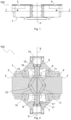
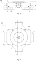
- Figure 1 is a front and elevation view of a first embodiment of the vise 100 according to the present invention.
- the numerical reference 1 denotes the body of the vise 100, and the numerical references 3 and 4 denote the jaws. As a matter of fact, it is a vise 100 with two opposite jaws.
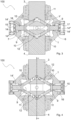
- Figure 2 is a sectional plan view considered on the plane M-M of figure 1 .
- the vise 100 is shown closed, that is, with the jaws 3 and 4 in abutment against each other.
- the jaws 3 and 4 are housed in respective seats 3' and 4' obtained in the body 1 and, as will be clear from the following description, they are slidable into these seats 3', 4' in order to close the vise 100 by moving close to each other, and to open the vise 100 by moving away from each other.
- each actuator 6, 7 of the jaws 3 and 4 is also housed in the body 1.
- the actuators 6 and 7 are hydraulic actuators, i.e., fed with pressurized oil, e.g. up to 100 bars.
- each actuator 6, 7 comprises a cylinder 14 within the body 1 of the vise 100, in which a piston 15 moves in alternating motion in response to the thrust exerted by the pressurized oil, which can be fed ahead or behind the piston 15 via suitable oil passages 20 that will be described further below.
- the pistons 15 of the actuators 6 and 7 move in alternating motion on the axis X-X (direction of piston displacement), which is orthogonal to the direction along which the jaws 3 and 4 move.
- a thrust element 9 is fixed to each piston 15.
- the thrust element 9 comprises a substantially cylindrical element 16 definable as a shaft, which extends through a corresponding seat 17 of the body 1 of the vise 100, thus achieving with the latter a slidable and sealing coupling thanks to an O-ring seal 17'.
- the shaft 16 supports two walls 10 and 11 that are inclined, and in particular divergent, with respect to the axis X-X and whose height extent is on planes orthogonal to the lying plane of the jaws 3 and 4.
- the angle between the inclined walls 10 and 11 is 30°; in general, this angle is in the range 20° - 60°.
- Figure 3 is a sectional plan view considered on the plane M-M of figure 1 . Comparing figures 2 and 3 , it can be seen that in figure 3 the jaws 3 and 4 are spaced apart from each other, and in particular they are in an intermediate position between the closed position shown in figure 2 , and the open position shown in figure 4 .
- the inclined walls 10 and 11 slidingly engage corresponding guides 12 of the jaws 3 and 4 which are inclined guides and converge like the walls 10 and 11.
- the guides 12 are formed directly in the jaws 3 and 4 by removing material from solid.
- the guides 12 define in each jaw 3, 4 a wedge-shaped guide in which the walls of the thrust element 9 of both actuators 6, 7 are simultaneously engaged.
- the guides 12 of the jaw 3 are simultaneously engaged by the wall 11 of the actuator 6 and the wall 11 of the actuator 7; the guides 12 of the jaw 4 are simultaneously engaged by the wall 10 of the actuator 6 and the wall 10 of the actuator 7.
- this configuration is referred to as double reverse wedge and allows the movement of the jaws 3 and 4 to be synchronously controlled, that is, such that jaws 3 and 4 move in sync.
- This measure makes the vise 100 self-centering, that is, it allows the workpieces to be always clamped on the workpiece gripping axis Y, and allows the same clamping force to be applied by the two jaws 3 and 4, that is, a jaw 3 always exerts on the workpiece the same pressure of the other jaw 4.
- the actuators 6 and 7 are shown with the respective pistons 15 in a more rearward position in the respective cylinder 14, compared to the fully forward position shown in figure 2 .
- the vise 100 is made to be symmetrical with respect to the workpiece gripping axis Y, i.e., the actuators 6-7 are symmetrical with respect to the axis Y, and the jaws 3-4 are also symmetrical with respect to the axis Y, the movements of the jaws 3 and 4 can only be synchronous. Thank to this arrangement the vise is self-centering, i.e., the jaws 3-4 move to close on the workpiece to be clamped on the axis Y simultaneously. Furthermore, a given displacement of the pistons 15 results in a corresponding and univocal displacement of both the jaws 3 and 4.
- Figure 4 is a sectional plan view considered on the plane M-M of figure 1 . Comparing figures 2 , 3 and 4 , it can be seen that in figure 4 the jaws 3 and 4 are fully open: the pistons 15 have reached the bottom dead point in the corresponding cylinder 14. The inclined walls 10 and 11 remain partially inserted in the respective seats 12 of the jaws 3 and 4, i.e. they never come out completely.
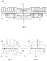
- Figure 5 is a vertical sectional view considered on the plane B-B of figure 4 , which is the same plane on which the axis of displacement of the two jaws 3 and 4 lies.
- Reference number 13 denotes the lying plane of the jaws 3 and 4, which is the sliding plane as well.
- the lying and sliding plane 13 is defined by a roller bearing shown enlarged in figures 6 and 7 .
- Figures 6 and 7 are enlargements of the circled portion K of figure 5 and show the jaw 4 during an opening movement, or while gripping a workpiece with reduced force, and in the position closed on a workpiece positioned on the workpiece gripping axis Y, respectively.
- a bearing 22 with rollers 22' is inserted between the jaws 3 and 4 and the body 1 of the vise 100: the upper surface of the rollers defines the lying and sliding plane 13 of the jaws 3 and 4.
- the rollers 22' are metal rollers that roll on a race 22".
- the race 22" is cemented, hardened and ground to a hardness in the range of 58-62 HRC.
- an elastic element 23 for example a gasket elastically deformable between a squeezed configuration and a configuration with a circular cross-section, with a diameter equal to that of the rollers 22', is inserted between the first roller 22' of the bearing 22 and the body 1 of the vise 100, i.e. in a position radially more inward with respect to the axis Y
- the elastic element 23 has this function:
- the backward movement of the jaws 3 and 4 to achieve the elastic recovery of the elastic element 23 and to grip the workpiece with reduced pressure is less than 1 mm.
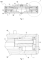
- Figure 8 is a sectional vertical view of the vise 100 considered on the plane M-M of figure 11 . It can be seen that the shaft 16 of each actuator 6-7 is offset from the respective piston 15, i.e., the elements 15 and 16 are not coaxial. This feature is best seen in figure 9 , which is an enlargement of the portion A of figure 8 . As can be seen, there is an offset ⁇ of, for example, 3 mm between the axis of the piston 15 and the axis of the shaft 16.
- the wall of the body 1 of the vise can be thickened where necessary, without this leading to an increase in the overall height H of the vise 1: as will be described later, the passages 20 for delivering the pressurized oil can be made in the thickened wall, as an alternative to the solution of arranging pipes or ducts outside the body 1.
- Figure 10 shows the vise 100 in a front and elevation view.
- the reference H denotes the height of the vise 100.
- the height H of the vise 100 is 69.5 cm.
- the clamping force of the jaws 3 and 4 is more than 2000 kg.
- the vise 100 made without anti-friction surface treatments and without roller bearings 22, but by providing for the simple sliding of the jaws 3 and 4 into their respective seats 3' and 4, it provides a clamping force of approximately 2220 kg.
- the clamping force of the jaws 3-4 is just over 3000 kg.
- Figure 11 shows the vise 100 in a top, plan, view.
- Reference 20' in figures 10 and 11 denotes supply nozzles of the pressurized oil.
- Figure 12 is a vertical sectional view of the vise 100 considered in the plane A-A of figure 11
- figure 13 is a vertical sectional view of the vise 100 considered in the plane B-B of figure 11 .
- These sections show the passages 20 and 21 obtained in the body 1 of the vise 100 for the pressurized oil delivery.
- the passages 20 and 21 extend at the thickened wall 19 of the body 1 of the vise 100.
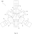
- Figure 14 is a schematic and plan view of a second embodiment 200 of the vise according to the present invention.
- the vise 200 differs from the vise 100 in that it includes three jaws 3-5 arranged in a 120° configuration around the workpiece gripping axis Y, and three actuators 6-8 also arranged in a 120° configuration around the axis Y
- the actuators 6-8 alternate with the jaws 3-5, meaning that an actuator 6-8 is interposed between two jaws 3-5 and each actuator applies its thrust simultaneously on two jaws.
- This configuration can be defined as an inverted triple wedge.
Landscapes
- Engineering & Computer Science (AREA)
- Mechanical Engineering (AREA)
- Jigs For Machine Tools (AREA)
- Mechanical Treatment Of Semiconductor (AREA)
- Adhesives Or Adhesive Processes (AREA)
Claims (14)
- Selbstzentrierender Schraubstock (100, 200), umfassend einen Körper (1), zwei oder mehr an den Körper (1) angebrachte Spannklauen (3-5) und Stellglieder (6-8) der Spannklauen (3-5),wobei die Spannklauen (3-5) in Bezug auf den Körper (1) auf einer Liegeebene (13) der Spannklauen (3-5) in Richtung zu und weg von einer Werkstückgreifachse (Y) beweglich sind, um ein Werkstück auf der Werkstückgreifachse (Y) zu klemmen und das Werkstück in Reaktion auf die von den Stellgliedern (6-8) ausgeübten Belastungen freizugeben,dadurch gekennzeichnet, dassjedes Stellglied (6-8) ein Schiebeelement (9) umfasst, das in Reaktion auf die durch ein dem Schraubstock (100, 200) zugeführtes Fluid ausgeübten Beanspruchungen zu Verschiebungen parallel zur Liegeebene der Klauen (3-5) fähig ist, undjede Klaue (3-5) zwei Führungen (12) umfasst, die geneigt und symmetrisch in Bezug auf die Verschiebungsrichtung (B-B) der Klaue (3-5) sind, unddas Schiebeelement (9) zwei Wände (10, 11) umfasst, die geneigt und symmetrisch in Bezug auf die Verschiebungsrichtung (X-X) desselben Schiebeelements (9) sind, unddas Stellglied (6-8) seine eigene Schubkraft gleichzeitig auf zwei Klauen (3-4; 4-5; 3-5) ausübt durch gleitenden Eingriff der Führungen (12) der beiden Klauen (3-5) mit seinen eigenen geneigten Wänden (10, 11).
- Schraubstock (100, 200) nach Anspruch 1, dadurch gekennzeichnet, dass die Verschiebungsrichtung (B-B) einer Klaue (3-5) quer zur Verschiebungsrichtung (X-X) der entsprechenden Schiebeelemente (9) verläuft und bei der Ausführung des Schraubstocks (100) mit zwei Klauen (3, 4) höchstens orthogonal ist.
- Schraubstock (100, 200) nach Anspruch 1 oder Anspruch 2, wobei die Stellglieder (6-8) hydraulisch oder pneumatisch sind und jeweils einen im Körper (1) des Schraubstocks (100, 200) ausgebildeten Zylinder (14) und einen in dem Zylinder (14) bewegbaren Kolben (15) umfassen, wobei sich das Schiebeelement (9) außerhalb des Zylinders (14) befindet und an dem Kolben (15) befestigt ist, um sich zusammen mit diesem zu bewegen, und der Kolben (15) Vorwärts- und Rückwärtsbewegungen ausführen kann, je nachdem, ob ein unter Druck stehendes Fluid in den Zylinder (14) stromaufwärts oder stromabwärts des Kolbens (15) zugeführt wird.
- Schraubstock (100, 200) nach Anspruch 3, umfassend eine Welle (16), die den Kolben (15) mit den geneigten Wänden (10, 11) verbindet, wobei die Welle (16) gleitend und abdichtend durch einen entsprechenden Sitz (17) des Körpers (1) eingesetzt ist, und wobei die Welle (16) gegenüber dem Kolben (15) versetzt ist.
- Schraubstock (100, 200) nach Anspruch 4, wobei der Zylinder (14) zwischen einer oberen Wand (18) und einer unteren Wand (19) des Körpers (1) eingeschlossen ist und Zuführungskanäle (20, 21) zum Zuführen eines unter Druck stehenden Fluids entweder in der oberen Wand (18) oder der unteren Wand (19) in distaler Beziehung bezüglich der Wellen (16) der Stellglieder (6-8) ausgebildet sind.
- Schraubstock (100, 200) nach einem der vorhergehenden Ansprüche 3-5, wobei der Winkel zwischen den geneigten Wänden (10, 11) der Stellglieder (6-8) im Bereich von 20° - 60° vorgesehen ist und dem Winkel zwischen den Führungen (12) jeder Klaue (3-5) entspricht.
- Schraubstock (100, 200) nach einem der vorhergehenden Ansprüche 1-6, wobei die geneigten Wände (10, 11), die gleitend in die entsprechenden Führungen (12) der Klauen (3-5) eingesetzt sind, eine schiefe Ebenenverbindung erzielen.
- Schraubstock (100, 200) nach einem der vorhergehenden Ansprüche 1-7, umfassend zwei Klauen (3, 4), die sich in Bezug auf die Werkstückgreifachse (Y) gegenüberliegen und entlang einer ersten Richtung oder ersten Verschiebeachse verschiebbar sind, und zwei Stellglieder (6, 7), die sich in Bezug auf die Werkstückgreifachse (Y) gegenüberliegen, wobei sich die Schiebeelemente (9) der Stellglieder (6, 7) entlang einer zweiten Richtung oder zweiten Verschiebeachse bewegen, die orthogonal zur ersten Richtung oder ersten Verschiebeachse ist, gemäß einer Konfiguration, die als doppelt umgekehrte Keilkonfiguration definiert ist.
- Schraubstock (100, 200) nach Anspruch 8, wobei der Winkel zwischen den geneigten Wänden (10, 11) der Stellglieder (6, 7) 30° beträgt.
- Schraubstock (100, 200) nach einem der vorhergehenden Ansprüche 1-7, umfassend drei um die Werkstückgreifachse (Y) angeordnete Klauen (3-5) mit einer 120°-Konfiguration und drei um die Werkstückgreifachse (Y) angeordnete Stellglieder (6-8) mit einer 120°-Konfiguration, wobei jedes Stellglied (6- 8) zwischen zwei Klauen (3-5) angeordnet ist.
- Schraubstock (100, 200) nach einem der vorhergehenden Ansprüche 1-10, umfassend ein Rollenlager (22), das zwischen dem Körper (1) des Schraubstocks (100, 200) und jeder Klaue (3-5) angeordnet ist, wobei die Rollen (22) die Liegeebene (13) der Klauen (3-5) definieren.
- Schraubstock (100, 200) nach Anspruch 11, wobei die Rollenlager (22) ein elastisches Element (23) umfassen, und wobei das elastische Element (23) zwischen einer verformten Konfiguration, bei der das elastische Element (23) zwischen den Rollen (22) und dem Körper (1) des Schraubstocks (100, 200) gepresst ist, wenn die Klauen (3-5) geschlossen sind, und einer nicht verformten Konfiguration, wenn die Klauen (3-5) geöffnet sind, elastisch verformbar ist.
- Schraubstock (100, 200) nach Anspruch 12, wobei das elastische Element (23) in Bezug auf die Werkstückgreifachse (Y) radial weiter innen als die Rollen (22) angeordnet ist.
- Verwendung des Schraubstocks (100, 200) nach Anspruch 12 oder Anspruch 13 in einer numerisch gesteuerten Werkzeugmaschine zum Einspannen und Halten eines Werkstücks auf der Werkstückgreifachse (Y), wobei die Stellglieder (6-8) zum Schieben der Klauen (3-5) betätigt werden und sich gleichzeitig bewegen, um sich auf dem Werkstück zu schließen, und somit eine Verformung des elastischen Elements (23) bewirken, und zum Auflösen des Griffs der Klauen (3- 5) auf dem Werkstück, d. h. um den ausgeübten Druck so weit zu verringern, dass das elastische Element (23) in die nicht verformte Konfiguration zurückkehrt, und dabei gleichzeitig das Werkstück hält.
Applications Claiming Priority (2)
| Application Number | Priority Date | Filing Date | Title |
|---|---|---|---|
| IT102021000007670A IT202100007670A1 (it) | 2021-03-29 | 2021-03-29 | Morsa autocentrante |
| PCT/IB2022/052026 WO2022208190A1 (en) | 2021-03-29 | 2022-03-08 | Self-centering vise |
Publications (3)
| Publication Number | Publication Date |
|---|---|
| EP4291353A1 EP4291353A1 (de) | 2023-12-20 |
| EP4291353C0 EP4291353C0 (de) | 2024-09-11 |
| EP4291353B1 true EP4291353B1 (de) | 2024-09-11 |
Family
ID=76269998
Family Applications (1)
| Application Number | Title | Priority Date | Filing Date |
|---|---|---|---|
| EP22709057.8A Active EP4291353B1 (de) | 2021-03-29 | 2022-03-08 | Selbstzentrierender schraubstock |
Country Status (4)
| Country | Link |
|---|---|
| US (1) | US20240181602A1 (de) |
| EP (1) | EP4291353B1 (de) |
| IT (1) | IT202100007670A1 (de) |
| WO (1) | WO2022208190A1 (de) |
Families Citing this family (1)
| Publication number | Priority date | Publication date | Assignee | Title |
|---|---|---|---|---|
| IT202300003696A1 (it) * | 2023-03-01 | 2024-09-01 | Tecno Art Di Nardini Andrea | Gruppo di tenuta e relativo apparato per eseguire lavorazioni su un componente |
Family Cites Families (2)
| Publication number | Priority date | Publication date | Assignee | Title |
|---|---|---|---|---|
| US4913481A (en) * | 1988-09-13 | 1990-04-03 | Applied Power Inc. | Clean room gripper |
| US10099384B1 (en) * | 2017-09-30 | 2018-10-16 | Quartet Medtronics Inc | Industrial wedge-type gripper mechanism |
-
2021
- 2021-03-29 IT IT102021000007670A patent/IT202100007670A1/it unknown
-
2022
- 2022-03-08 EP EP22709057.8A patent/EP4291353B1/de active Active
- 2022-03-08 WO PCT/IB2022/052026 patent/WO2022208190A1/en not_active Ceased
- 2022-03-08 US US18/553,507 patent/US20240181602A1/en active Pending
Also Published As
| Publication number | Publication date |
|---|---|
| EP4291353C0 (de) | 2024-09-11 |
| EP4291353A1 (de) | 2023-12-20 |
| IT202100007670A1 (it) | 2022-09-29 |
| WO2022208190A1 (en) | 2022-10-06 |
| US20240181602A1 (en) | 2024-06-06 |
Similar Documents
| Publication | Publication Date | Title |
|---|---|---|
| US7654178B2 (en) | Hydraulic chuck with independently moveable jaws | |
| US9321109B2 (en) | Power operated chuck | |
| US20080237957A1 (en) | Adjustable stroke gripper | |
| US7854456B2 (en) | Dual rod gripper | |
| EP4291353B1 (de) | Selbstzentrierender schraubstock | |
| US7040629B2 (en) | Clamping device for elongated workpieces | |
| US7299671B2 (en) | Bending device for bending machine | |
| US7739871B2 (en) | Press-driven tool actuation system | |
| JPH1037911A (ja) | 空圧式アクチュエータ装置 | |
| CN106424775A (zh) | 一种机床液压尾架系统 | |
| US4890541A (en) | Fluid-operated actuator with force multiplication | |
| CN214444839U (zh) | 一种灵活定位夹持工件的铣床 | |
| JP2015058528A (ja) | 引き込みチャック | |
| US8984922B2 (en) | Method of and apparatus for positioning a tool | |
| AU2013304707B2 (en) | Lifting apparatus having a toggle lever mechanism | |
| CN108788575B (zh) | 薄壁钻焊接机 | |
| US20050252269A1 (en) | Toggle press | |
| JPS58196917A (ja) | 鋸盤のバイス装置 | |
| EP1329283B1 (de) | Spann- beziehungsweise Greifsystem | |
| CN209868001U (zh) | 电动门泵减速器壳体的机加工工装 | |
| GB2110139A (en) | Roll forging machines | |
| KR20000047388A (ko) | 크로스롤 압연기 | |
| JP3125876U (ja) | 空圧進退駆動型電動加工装置 | |
| CN206263279U (zh) | 一种机床液压尾架系统 | |
| EP1728593B1 (de) | Pneumatischer Schraubstock mit integrierter Steuerungs- und Sicherheitseinrichtung |
Legal Events
| Date | Code | Title | Description |
|---|---|---|---|
| STAA | Information on the status of an ep patent application or granted ep patent |
Free format text: STATUS: UNKNOWN |
|
| STAA | Information on the status of an ep patent application or granted ep patent |
Free format text: STATUS: THE INTERNATIONAL PUBLICATION HAS BEEN MADE |
|
| PUAI | Public reference made under article 153(3) epc to a published international application that has entered the european phase |
Free format text: ORIGINAL CODE: 0009012 |
|
| STAA | Information on the status of an ep patent application or granted ep patent |
Free format text: STATUS: REQUEST FOR EXAMINATION WAS MADE |
|
| 17P | Request for examination filed |
Effective date: 20230911 |
|
| AK | Designated contracting states |
Kind code of ref document: A1 Designated state(s): AL AT BE BG CH CY CZ DE DK EE ES FI FR GB GR HR HU IE IS IT LI LT LU LV MC MK MT NL NO PL PT RO RS SE SI SK SM TR |
|
| GRAP | Despatch of communication of intention to grant a patent |
Free format text: ORIGINAL CODE: EPIDOSNIGR1 |
|
| STAA | Information on the status of an ep patent application or granted ep patent |
Free format text: STATUS: GRANT OF PATENT IS INTENDED |
|
| INTG | Intention to grant announced |
Effective date: 20240412 |
|
| DAV | Request for validation of the european patent (deleted) | ||
| DAX | Request for extension of the european patent (deleted) | ||
| GRAS | Grant fee paid |
Free format text: ORIGINAL CODE: EPIDOSNIGR3 |
|
| GRAA | (expected) grant |
Free format text: ORIGINAL CODE: 0009210 |
|
| STAA | Information on the status of an ep patent application or granted ep patent |
Free format text: STATUS: THE PATENT HAS BEEN GRANTED |
|
| AK | Designated contracting states |
Kind code of ref document: B1 Designated state(s): AL AT BE BG CH CY CZ DE DK EE ES FI FR GB GR HR HU IE IS IT LI LT LU LV MC MK MT NL NO PL PT RO RS SE SI SK SM TR |
|
| REG | Reference to a national code |
Ref country code: GB Ref legal event code: FG4D |
|
| REG | Reference to a national code |
Ref country code: CH Ref legal event code: EP |
|
| REG | Reference to a national code |
Ref country code: DE Ref legal event code: R096 Ref document number: 602022006068 Country of ref document: DE |
|
| REG | Reference to a national code |
Ref country code: IE Ref legal event code: FG4D |
|
| U01 | Request for unitary effect filed |
Effective date: 20240911 |
|
| U07 | Unitary effect registered |
Designated state(s): AT BE BG DE DK EE FI FR IT LT LU LV MT NL PT RO SE SI Effective date: 20241001 |
|
| PG25 | Lapsed in a contracting state [announced via postgrant information from national office to epo] |
Ref country code: NO Free format text: LAPSE BECAUSE OF FAILURE TO SUBMIT A TRANSLATION OF THE DESCRIPTION OR TO PAY THE FEE WITHIN THE PRESCRIBED TIME-LIMIT Effective date: 20241211 |
|
| PG25 | Lapsed in a contracting state [announced via postgrant information from national office to epo] |
Ref country code: GR Free format text: LAPSE BECAUSE OF FAILURE TO SUBMIT A TRANSLATION OF THE DESCRIPTION OR TO PAY THE FEE WITHIN THE PRESCRIBED TIME-LIMIT Effective date: 20241212 |
|
| PG25 | Lapsed in a contracting state [announced via postgrant information from national office to epo] |
Ref country code: HR Free format text: LAPSE BECAUSE OF FAILURE TO SUBMIT A TRANSLATION OF THE DESCRIPTION OR TO PAY THE FEE WITHIN THE PRESCRIBED TIME-LIMIT Effective date: 20240911 |
|
| PG25 | Lapsed in a contracting state [announced via postgrant information from national office to epo] |
Ref country code: ES Free format text: LAPSE BECAUSE OF FAILURE TO SUBMIT A TRANSLATION OF THE DESCRIPTION OR TO PAY THE FEE WITHIN THE PRESCRIBED TIME-LIMIT Effective date: 20240911 Ref country code: RS Free format text: LAPSE BECAUSE OF FAILURE TO SUBMIT A TRANSLATION OF THE DESCRIPTION OR TO PAY THE FEE WITHIN THE PRESCRIBED TIME-LIMIT Effective date: 20241211 |
|
| PG25 | Lapsed in a contracting state [announced via postgrant information from national office to epo] |
Ref country code: RS Free format text: LAPSE BECAUSE OF FAILURE TO SUBMIT A TRANSLATION OF THE DESCRIPTION OR TO PAY THE FEE WITHIN THE PRESCRIBED TIME-LIMIT Effective date: 20241211 Ref country code: NO Free format text: LAPSE BECAUSE OF FAILURE TO SUBMIT A TRANSLATION OF THE DESCRIPTION OR TO PAY THE FEE WITHIN THE PRESCRIBED TIME-LIMIT Effective date: 20241211 Ref country code: HR Free format text: LAPSE BECAUSE OF FAILURE TO SUBMIT A TRANSLATION OF THE DESCRIPTION OR TO PAY THE FEE WITHIN THE PRESCRIBED TIME-LIMIT Effective date: 20240911 Ref country code: GR Free format text: LAPSE BECAUSE OF FAILURE TO SUBMIT A TRANSLATION OF THE DESCRIPTION OR TO PAY THE FEE WITHIN THE PRESCRIBED TIME-LIMIT Effective date: 20241212 Ref country code: ES Free format text: LAPSE BECAUSE OF FAILURE TO SUBMIT A TRANSLATION OF THE DESCRIPTION OR TO PAY THE FEE WITHIN THE PRESCRIBED TIME-LIMIT Effective date: 20240911 |
|
| PG25 | Lapsed in a contracting state [announced via postgrant information from national office to epo] |
Ref country code: IS Free format text: LAPSE BECAUSE OF FAILURE TO SUBMIT A TRANSLATION OF THE DESCRIPTION OR TO PAY THE FEE WITHIN THE PRESCRIBED TIME-LIMIT Effective date: 20250111 |
|
| PG25 | Lapsed in a contracting state [announced via postgrant information from national office to epo] |
Ref country code: SM Free format text: LAPSE BECAUSE OF FAILURE TO SUBMIT A TRANSLATION OF THE DESCRIPTION OR TO PAY THE FEE WITHIN THE PRESCRIBED TIME-LIMIT Effective date: 20240911 |
|
| PG25 | Lapsed in a contracting state [announced via postgrant information from national office to epo] |
Ref country code: CZ Free format text: LAPSE BECAUSE OF FAILURE TO SUBMIT A TRANSLATION OF THE DESCRIPTION OR TO PAY THE FEE WITHIN THE PRESCRIBED TIME-LIMIT Effective date: 20240911 Ref country code: PL Free format text: LAPSE BECAUSE OF FAILURE TO SUBMIT A TRANSLATION OF THE DESCRIPTION OR TO PAY THE FEE WITHIN THE PRESCRIBED TIME-LIMIT Effective date: 20240911 |
|
| PG25 | Lapsed in a contracting state [announced via postgrant information from national office to epo] |
Ref country code: SK Free format text: LAPSE BECAUSE OF FAILURE TO SUBMIT A TRANSLATION OF THE DESCRIPTION OR TO PAY THE FEE WITHIN THE PRESCRIBED TIME-LIMIT Effective date: 20240911 |
|
| PLBE | No opposition filed within time limit |
Free format text: ORIGINAL CODE: 0009261 |
|
| STAA | Information on the status of an ep patent application or granted ep patent |
Free format text: STATUS: NO OPPOSITION FILED WITHIN TIME LIMIT |
|
| 26N | No opposition filed |
Effective date: 20250612 |
|
| PG25 | Lapsed in a contracting state [announced via postgrant information from national office to epo] |
Ref country code: MC Free format text: LAPSE BECAUSE OF FAILURE TO SUBMIT A TRANSLATION OF THE DESCRIPTION OR TO PAY THE FEE WITHIN THE PRESCRIBED TIME-LIMIT Effective date: 20240911 |
|
| REG | Reference to a national code |
Ref country code: CH Ref legal event code: H13 Free format text: ST27 STATUS EVENT CODE: U-0-0-H10-H13 (AS PROVIDED BY THE NATIONAL OFFICE) Effective date: 20251023 |
|
| U90 | Renewal fees not paid: noting of loss of rights |
Free format text: RENEWAL FEE NOT PAID FOR YEAR 04 Effective date: 20251015 |
|
| PG25 | Lapsed in a contracting state [announced via postgrant information from national office to epo] |
Ref country code: CH Free format text: LAPSE BECAUSE OF NON-PAYMENT OF DUE FEES Effective date: 20250331 |
|
| PG25 | Lapsed in a contracting state [announced via postgrant information from national office to epo] |
Ref country code: IE Free format text: LAPSE BECAUSE OF NON-PAYMENT OF DUE FEES Effective date: 20250308 |
|
| U93 | Unitary patent lapsed |
Free format text: RENEWAL FEE NOT PAID Effective date: 20250331 |