EP4291272B1 - Ausgabekopf für eine vorrichtung zur ausgabe eines flüssigen oder pulverigen produkts in die nase - Google Patents
Ausgabekopf für eine vorrichtung zur ausgabe eines flüssigen oder pulverigen produkts in die nase Download PDFInfo
- Publication number
- EP4291272B1 EP4291272B1 EP22708993.5A EP22708993A EP4291272B1 EP 4291272 B1 EP4291272 B1 EP 4291272B1 EP 22708993 A EP22708993 A EP 22708993A EP 4291272 B1 EP4291272 B1 EP 4291272B1
- Authority
- EP
- European Patent Office
- Prior art keywords
- head
- radial
- dispensing
- tip
- external
- Prior art date
- Legal status (The legal status is an assumption and is not a legal conclusion. Google has not performed a legal analysis and makes no representation as to the accuracy of the status listed.)
- Active
Links
Images

Classifications
-
- A—HUMAN NECESSITIES
- A61—MEDICAL OR VETERINARY SCIENCE; HYGIENE
- A61M—DEVICES FOR INTRODUCING MEDIA INTO, OR ONTO, THE BODY; DEVICES FOR TRANSDUCING BODY MEDIA OR FOR TAKING MEDIA FROM THE BODY; DEVICES FOR PRODUCING OR ENDING SLEEP OR STUPOR
- A61M15/00—Inhalators
- A61M15/0065—Inhalators with dosage or measuring devices
-
- A—HUMAN NECESSITIES
- A61—MEDICAL OR VETERINARY SCIENCE; HYGIENE
- A61M—DEVICES FOR INTRODUCING MEDIA INTO, OR ONTO, THE BODY; DEVICES FOR TRANSDUCING BODY MEDIA OR FOR TAKING MEDIA FROM THE BODY; DEVICES FOR PRODUCING OR ENDING SLEEP OR STUPOR
- A61M11/00—Sprayers or atomisers specially adapted for therapeutic purposes
- A61M11/006—Sprayers or atomisers specially adapted for therapeutic purposes operated by applying mechanical pressure to the liquid to be sprayed or atomised
- A61M11/007—Syringe-type or piston-type sprayers or atomisers
-
- A—HUMAN NECESSITIES
- A61—MEDICAL OR VETERINARY SCIENCE; HYGIENE
- A61M—DEVICES FOR INTRODUCING MEDIA INTO, OR ONTO, THE BODY; DEVICES FOR TRANSDUCING BODY MEDIA OR FOR TAKING MEDIA FROM THE BODY; DEVICES FOR PRODUCING OR ENDING SLEEP OR STUPOR
- A61M15/00—Inhalators
- A61M15/08—Inhaling devices inserted into the nose
-
- B—PERFORMING OPERATIONS; TRANSPORTING
- B05—SPRAYING OR ATOMISING IN GENERAL; APPLYING FLUENT MATERIALS TO SURFACES, IN GENERAL
- B05B—SPRAYING APPARATUS; ATOMISING APPARATUS; NOZZLES
- B05B11/00—Single-unit hand-held apparatus in which flow of contents is produced by the muscular force of the operator at the moment of use
- B05B11/01—Single-unit hand-held apparatus in which flow of contents is produced by the muscular force of the operator at the moment of use characterised by the means producing the flow
- B05B11/02—Membranes or pistons acting on the contents inside the container, e.g. follower pistons
-
- B—PERFORMING OPERATIONS; TRANSPORTING
- B05—SPRAYING OR ATOMISING IN GENERAL; APPLYING FLUENT MATERIALS TO SURFACES, IN GENERAL
- B05B—SPRAYING APPARATUS; ATOMISING APPARATUS; NOZZLES
- B05B11/00—Single-unit hand-held apparatus in which flow of contents is produced by the muscular force of the operator at the moment of use
- B05B11/01—Single-unit hand-held apparatus in which flow of contents is produced by the muscular force of the operator at the moment of use characterised by the means producing the flow
- B05B11/02—Membranes or pistons acting on the contents inside the container, e.g. follower pistons
- B05B11/025—Membranes or pistons acting on the contents inside the container, e.g. follower pistons with stepwise advancement of the piston, e.g. for spraying a predetermined quantity of content
-
- A—HUMAN NECESSITIES
- A61—MEDICAL OR VETERINARY SCIENCE; HYGIENE
- A61M—DEVICES FOR INTRODUCING MEDIA INTO, OR ONTO, THE BODY; DEVICES FOR TRANSDUCING BODY MEDIA OR FOR TAKING MEDIA FROM THE BODY; DEVICES FOR PRODUCING OR ENDING SLEEP OR STUPOR
- A61M15/00—Inhalators
- A61M15/0028—Inhalators using prepacked dosages, one for each application, e.g. capsules to be perforated or broken-up
- A61M15/003—Inhalators using prepacked dosages, one for each application, e.g. capsules to be perforated or broken-up using capsules, e.g. to be perforated or broken-up
- A61M15/0033—Details of the piercing or cutting means
- A61M15/0035—Piercing means
- A61M15/0036—Piercing means hollow piercing means
-
- A—HUMAN NECESSITIES
- A61—MEDICAL OR VETERINARY SCIENCE; HYGIENE
- A61M—DEVICES FOR INTRODUCING MEDIA INTO, OR ONTO, THE BODY; DEVICES FOR TRANSDUCING BODY MEDIA OR FOR TAKING MEDIA FROM THE BODY; DEVICES FOR PRODUCING OR ENDING SLEEP OR STUPOR
- A61M15/00—Inhalators
- A61M15/0028—Inhalators using prepacked dosages, one for each application, e.g. capsules to be perforated or broken-up
- A61M15/003—Inhalators using prepacked dosages, one for each application, e.g. capsules to be perforated or broken-up using capsules, e.g. to be perforated or broken-up
- A61M15/0033—Details of the piercing or cutting means
- A61M15/004—Details of the piercing or cutting means with fixed piercing or cutting means
-
- B—PERFORMING OPERATIONS; TRANSPORTING
- B05—SPRAYING OR ATOMISING IN GENERAL; APPLYING FLUENT MATERIALS TO SURFACES, IN GENERAL
- B05B—SPRAYING APPARATUS; ATOMISING APPARATUS; NOZZLES
- B05B15/00—Details of spraying plant or spraying apparatus not otherwise provided for; Accessories
- B05B15/14—Arrangements for preventing or controlling structural damage to spraying apparatus or its outlets, e.g. for breaking at desired places; Arrangements for handling or replacing damaged parts
- B05B15/16—Arrangements for preventing or controlling structural damage to spraying apparatus or its outlets, e.g. for breaking at desired places; Arrangements for handling or replacing damaged parts for preventing non-intended contact between spray heads or nozzles and foreign bodies, e.g. nozzle guards
Definitions
- the present invention relates to a dispensing head for a nasal dispensing device for a fluid or powder product.
- Nasal dispensing devices are widely used and in a variety of applications. These devices comprise a dispensing head incorporating the dispensing orifice of the product, at least a portion of said head being intended to be inserted into the nostril of the user during dispensing of the product. The user then actuates the device to expel a dose of product into the nostril.
- the products dispensed by nasal dispensing devices can be expensive and/or must be dosed very precisely.
- the aim is therefore to obtain maximum efficiency of the dose of product dispensed into the nostril with each actuation.
- the depth of insertion of the dispensing head into the nostril has an effect on the distribution of the dose.
- insertion too deep can not only be painful, but also impair the correct distribution of the dose.
- a tip has been proposed that attaches to the dispensing head and not only limits the depth of insertion into the nostril, but also allows the dispensing head to be oriented to some extent in the nostril to optimize dose distribution.
- the documents WO9857690 And WO0027430 describe such tips.
- the size of the nostril can vary quite significantly, particularly due to many parameters, such as the user's gender, age, height or ethnic origin.
- a disadvantage of document tips WO9857690 And WO0027430 lies in the fact that they do not allow for taking into account the different dimensions of the nostrils, and that to overcome this drawback, it is It is necessary to provide a plurality of removable tips of different sizes, with the user choosing the size that suits them before use.
- This implementation requires the manufacture of a large number of tips, for example three or four sizes for each device, when only one of these tips will actually be used. This generates a significant additional manufacturing cost, increases the dimensions of the device's packaging, consumes more plastic material and therefore risks increasing environmental pollution.
- the present invention therefore relates to a nasal dispensing head for a fluid or powder product, comprising an axial end portion provided with a dispensing orifice, said axial end portion of said head being intended to be inserted into a nostril during actuation, said head comprising a tip adapted, during actuation, to rest on the entrance of the nostril to define the depth of insertion of said head into the nostril, said tip being axially movable on said head between at least two positions of use axially offset from one another, said tip comprising a hollow cylindrical axial sleeve arranged around a cylindrical portion of said head, said sleeve extending on the upper axial side by a radial flange which extends radially outwards, said flange radial bearing on the nose around the entrance of the nostril when actuated, said cylindrical part comprising at least two axially offset external radial recesses, and at least one flat extending axially in said cylindrical part, each flat comprising at least two
- said cylindrical part comprises two diametrically opposed flats, three external radial recesses and three ribs, each external radial recess extending over the periphery of said cylindrical part while being interrupted at each flat, and each rib extending over each of said two flats.
- said sleeve comprises two diametrically opposed internal radial projections.
- said radial flange has a radially external edge of rounded shape, in particular circular or oval.
- the present invention also relates to a fluid product dispensing device, comprising a reservoir and a dispensing member, such as a piston, slidably mounted in said reservoir, said device comprising a dispensing head as described above.
- said reservoir contains two doses of fluid product distributed in two successive actuations.
- the nasal dispensing device comprises a reservoir 10 containing two doses of fluid product.
- a dispensing member such as a piston 20, is slidably mounted in said reservoir 10. In the position before actuation of the device, shown in the figure 1 , said piston 20 acts as a stopper by isolating the contents of the reservoir 10.
- a dispensing head 30 is assembled on said reservoir 10 while being axially movable relative thereto.
- an axial displacement of the dispensing head 30 relative to the reservoir 10 causes the displacement of the piston 20 in the reservoir 10 and thus the dispensing of the fluid contained in said reservoir.
- the dispensing head 30 comprises a dispensing channel 33 which leads from a piercing tip 34 to a dispensing orifice 31 of the dispensing head 30. Upstream of the dispensing orifice 31, a spray profile may be provided, which may be of any known type and which is not shown in more detail in the drawing, to dispense the fluid in the form of a spray.
- the tank 10 is fixed in a body 50, which is therefore integral with said tank 10, and which moves together with it.
- the dispensing head 30 comprises a lower side skirt 32 adapted to cooperate with an actuating member 60.
- a finger rest element 80 is formed in a single piece with said dispensing head 30, or alternatively is assembled around it.
- Said actuating member 60 is axially movable inside said side skirt 32 of the dispensing head 30 to carry out the successive actuations of the device.
- the actuating member 60 comprises at least one inclined tab 61 which is adapted to cooperate with projections 51, 52 of the body 50 to carry out the successive actuations.
- a return spring 70 is mounted between the actuating member 60 and the dispensing head 30, to return said actuating member 60 to its starting position after each actuation.
- the stopper piston 20 isolates the contents of the reservoir 10 from the atmosphere.
- the user simultaneously presses on the finger rest 80 and on the actuating member 60, he will move said actuating member 60 inside the side skirt 32 of the dispensing head 30. This will push the body 50 axially upwards, by means of the tabs 61 which will push on the shoulder 51 of said body. This will compress the spring 70 and move the reservoir 10 relative to the dispensing head 30.
- the piercing end 34 of the dispensing channel 33 will pierce the stopper piston 20 to communicate the inside of the reservoir 10 with said expulsion channel 33.
- the spring 70 After dispensing the first dose, when the user releases the actuating member 60, the spring 70 will return it to its starting position. During this return of the actuating member 60, the reservoir and the body 50 do not return backwards, because these two components remain held in said dispensing head 30.
- the dispensing head 30 may include non-return means to prevent a return of said body 50 and/or said reservoir 10 backwards.
- the actuating member 60 returns under the effect of the return spring 70 to its rest position, the tabs 61 will position themselves under the second projection 52 of the body 50 which will allow the user to actuate the device a second time to dispense the second dose of fluid product.
- the dispensing device may include an indicator (not shown) to indicate to the user the dispensing of the first dose and the dispensing of the second dose. In this way, the user knows exactly where he is and whether or not the first dose has been dispensed.
- This indicator may include a viewing window formed in said dispensing head 30.
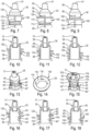
- the nasal dispensing device comprises a tip 100 which is disposed on the head 30 to define the depth of insertion of the dispensing head into the nostril.
- the sleeve 110 of the end piece 100 is force-fitted onto the cylindrical part 36 of said head 30.
- the force required to axially move the tip 100 on the head 30 between its positions of use is greater than the bearing force of said tip 100 on the nose during actuation. Thus, there is no risk of the tip moving on the head during actuation.
- the cylindrical part 36 comprises at least two axially offset external radial projections 37; 37'; 37" and the sleeve 110 comprises at least one internal radial recess 112.
- the internal radial recess 112 cooperates, in particular by snap-fastening, with a first radial projection 37 in a first position of use, which is an upper position of use, shown in the figure 4 .
- the internal radial recess 112 cooperates with a second radial projection 37', and in a third position of use, which is a lower position of use visible on the figure 6 , it cooperates with a third 37" radial projection.
- the radial projections of the head could be replaced by recesses, and the recess of the tip by a projection.
- the tip 100 comprises a peripheral internal radial recess 112. This makes it possible to avoid having to orient the tip angularly relative to the head.
- the radial recess 112 is arranged close to the radial flange 120, and the sleeve 110 then advantageously comprises a cutout 111, preferably peripheral, on its lower part to receive the radial projection(s) arranged below the radial projection which cooperates with the radial recess 112.
- each external radial projection 37; 37'; 37" is peripheral, forming a bead all around the head.
- the cylindrical part 36 comprises an external thread 38 and the sleeve 110 comprises an internal thread 115 cooperating with said external thread 38, the end piece 100 being movable in rotation on the head 30 between its positions of use.
- the friction between said internal and external threads 115, 38 prevents rotation of said tip 100 during actuation. In other words, there is no risk of the tip moving on the head during actuation.
- the external thread 38 is a female thread, that is to say that the thread is hollowed out in the cylindrical part 36 and the internal thread 115 is a male thread, that is to say that the thread projects radially inwards from said sleeve 110.
- the reverse implementation is also possible.
- three positions of use are defined, namely an upper position, shown in the Figures 7 and 10 , an intermediate position, represented on the Figures 8 and 11 , and a lower position, shown on the Figures 9 and 12 . It is then advantageous to provide a mark 113 on the outside of the sleeve 110 of the end piece 100, and a corresponding mark 39 on the head 30, in particular on a part of the head 30 arranged below the end piece 100. As visible in the Figures 7 to 9 , the correspondence of the reference 113 of the tip with the reference 39 of the head defines the respective position of use.
- resistance points can be provided on the external thread 38 and/or the internal thread 115 (not shown) to define these different positions of use of the tip.
- the cylindrical part 36 comprises at least two axially offset external radial recesses 40; 40'; 40".
- At least one flat 41 extends axially in said cylindrical part 36.
- two diametrically opposite flats are provided.
- Each flat 41 comprises at least two ribs 42; 42'; 42" extending radially outwards, each rib 42; 42'; 42" being arranged at a respective external radial recess 40; 40'; 40".
- three external radial recesses 40; 40'; 40" and three ribs 42; 42'; 42" are provided, each external radial recess 40; 40'; 40" extending on the periphery of the cylindrical part 36 while being interrupted at each flat 41, and each rib 42; 42'; 42” extending on each of the flats 41.
- the sleeve 110 comprises at least one internal radial projection 116.
- the sleeve 110 comprises two diametrically opposed internal radial projections 116.
- the internal diameter of said sleeve 110 at the internal radial projections 116 is greater than the external diameter of the cylindrical portion 36 at said at least one flat 41, approximately identical to the external diameter of the cylindrical portion 36 at each rib 42; 42'; 42", and less than the external diameter of the cylindrical portion 36 at each external radial recess 40; 40'; 40".
- the end piece 100 can slide axially on the head 30 when each internal radial projection 116 is arranged at a respective flat 41 and the end piece 100 cannot slide axially on the head 30 when each internal radial projection 116 is arranged in a respective external radial recess 40; 40'; 40", after rotation of the end piece 100 on the head 30.
- each internal radial projection 116 is arranged in a respective first radial recess 40.
- each internal radial projection 116 is arranged in a respective second radial recess 40'.
- each internal radial projection 116 is arranged in a respective third radial recess 40".
- the ribs 42; 42';42" serve to easily identify each of the axial positions of the end piece. Indeed, due to their extra thickness relative to the flat 41, they cooperate with the internal radial projection(s) 116 to form a resistance to the axial sliding of the end piece 100. Thus, these ribs do not prevent this sliding, but each rib makes it possible to precisely identify the axial position of each respective radial recess 40, 40', 40" .
- the user who wants to move from the upper position to the intermediate position, turns the end piece 100 such that each internal radial projection 116 is facing a respective flat 41 and presses on the end piece to move it axially downwards.
- the end piece 100 comprises a mark 113 on the sleeve 110, arranged at each internal radial projection 116.
- a second mark 114 can also be provided on the radial flange 120, also arranged at each internal radial projection 116. This makes it possible to guide the user to easily identify the angular position in which he can move the end piece axially relative to the head, by aligning the mark(s) 113, 114 with a flat 41.
- the operation of the device is as follows.
- the user Before use, the user adjusts the position of use of the tip 100 on the axial end of the head 30. He then inserts the head 30, at least its axial end, into his nostril. During this operation, the radial flange 120 of the tip 100 comes to rest on the wing of the nose, to define the depth of insertion of said head 30 in the nostril. The user then activates the device and the dose of product is dispensed into the nostril.
- the present invention therefore makes it possible to provide a nasal dispensing head that is simple and inexpensive to manufacture (in particular to mold) and assemble.
- This head is also simple and reliable to use by everyone. This is particularly advantageous in the field of pharmacy where the dosage of the product must be very precise and its effectiveness optimized due to the often high cost of the products to be dispensed.
Landscapes
- Health & Medical Sciences (AREA)
- Engineering & Computer Science (AREA)
- Life Sciences & Earth Sciences (AREA)
- Public Health (AREA)
- Animal Behavior & Ethology (AREA)
- Anesthesiology (AREA)
- Biomedical Technology (AREA)
- Heart & Thoracic Surgery (AREA)
- Hematology (AREA)
- Veterinary Medicine (AREA)
- General Health & Medical Sciences (AREA)
- Pulmonology (AREA)
- Bioinformatics & Cheminformatics (AREA)
- Otolaryngology (AREA)
- Mechanical Engineering (AREA)
- Biophysics (AREA)
- Infusion, Injection, And Reservoir Apparatuses (AREA)
- Medical Preparation Storing Or Oral Administration Devices (AREA)
- Containers And Packaging Bodies Having A Special Means To Remove Contents (AREA)
Claims (7)
- Kopf (30) zur intranasalen Verabreichung eines flüssigen oder pulverförmigen Produkts, mit einem axialen Endabschnitt (35), der mit einer Abgabeöffnung (31) versehen ist, wobei der axiale Endabschnitt (35) des Kopfes (30) zur Einführung in ein Nasenloch bei Betätigung bestimmt ist, der Kopf ein Ansatzstück (100) umfasst, das derart ausgelegt ist, dass es bei Betätigung am Eingang des Nasenlochs anliegt, um die Einführtiefe des Kopfes (30) in das Nasenloch zu definieren, wobei das Ansatzstück (100) auf dem Kopf (30) zwischen mindestens zwei axial gegeneinander versetzten Gebrauchsstellungen axial verschiebbar ist, das Ansatzstück (100) eine hohlzylindrische axiale Hülse (110) aufweist, die um einen zylindrischen Teil (36) des Kopfes (30) herum angeordnet ist, wobei die Hülse (110) an der oberen axialen Seite durch einen Radialflansch (120) verlängert ist, der radial nach außen verläuft, wobei bei Betätigung der Radialflansch (120) um den Nasenlocheingang herum an der Nase anliegt, dadurch gekennzeichnet, dass der zylindrische Teil (36) mindestens zwei äußere radiale Ausnehmungen (40, 40', 40") aufweist, die axial versetzt sind, und mindestens eine Abflachung (41), die sich axial in den zylindrischen Teil (36) erstreckt, wobei jede Abflachung (41) mindestens zwei Rippen (42; 42'; 42") aufweist, die sich radial nach außen erstrecken, wobei jede Rippe (42; 42'; 42") an einer radial äußeren Ausnehmung (40; 40'; 40") angeordnet ist, wobei die Hülse (110) mindestens einen inneren radialen Vorsprung (116) aufweist, wobei der Innendurchmesser der Hülse (110) an dem mindestens einen inneren radialen Vorsprung (116) größer ist als der Außendurchmesser des zylindrischen Teils (36) an der mindestens einen Abflachung (41), etwa gleich dem Außendurchmesser des zylindrischen Abschnitts (36) an jeder Rippe (42; 42'; 42"), und kleiner als der Außendurchmesser des zylindrischen Abschnitts (36) an jeder äußeren radialen Aussparung (40; 42'; 42"), sodass ein axiales Gleiten des Ansatzstücks (100) auf dem Kopf (30) möglich ist, wenn der mindestens eine innere radiale Vorsprung (116) an einer Abflachung (41) angeordnet ist, und ein axiales Gleiten des Ansatzstücks (100) auf dem Kopf (30) nicht möglich ist, wenn der mindestens eine innere radiale Vorsprung (116) in einer äußeren radialen Ausnehmung (40, 40'; 40") angeordnet ist, nachdem das Ansatzstück (100) auf dem Kopf (30) gedreht wurde, wobei in einer ersten Gebrauchsstellung der mindestens eine innere radiale Vorsprung (116) in einer ersten radialen Aussparung (40) angeordnet ist und in einer zweiten Gebrauchsstellung dieser in einer zweiten radialen Aussparung (40') angeordnet ist.
- Kopf nach Anspruch 1, bei dem der zylindrische Teil (36) zwei diametral gegenüberliegende Abflachungen (41), drei äußere radiale Aussparungen (40; 40'; 40") und drei Rippen (42; 42'; 42") aufweist, wobei jede äußere radiale Aussparung (40; 40'; 40") sich über den Umfang des zylindrischen Teils (36) erstreckt und an jeder Abflachung (41) unterbrochen ist, und jede Rippe (42; 42'; 42") sich über jede der beiden Abflachungen (41) erstreckt.
- Kopf nach Anspruch 1 oder 2, bei dem die Hülse (110) zwei einander diametral gegenüberliegende innere radiale Vorsprünge (116) aufweist.
- Kopf nach einem der vorhergehenden Ansprüche, bei dem der radiale Flansch (120) einen radial äußeren Rand mit einer abgerundeten Form, insbesondere einer kreisförmigen oder ovalen Form hat.
- Vorrichtung zur Abgabe eines flüssigen Produkts, mit einem Vorratsbehälter (10) und einem Abgabeorgan (20), beispielsweise einem Kolben, das gleitend in dem Vorratsbehälter (10) installiert ist, dadurch gekennzeichnet, dass die Vorrichtung einen Abgabekopf (30) gemäß einem der vorhergehenden Ansprüche aufweist.
- Vorrichtung nach Anspruch 5, bei der jeder Vorratsbehälter (10) eine Einzeldosis des flüssigen Produkts enthält, deren Abgabe durch eine einzige Betätigung erfolgt.
- Vorrichtung nach Anspruch 5, bei der der Vorratsbehälter (10) zwei Dosen des flüssigen Produkts enthält, deren Abgabe durch zwei aufeinanderfolgende Betätigungen erfolgt.
Applications Claiming Priority (2)
| Application Number | Priority Date | Filing Date | Title |
|---|---|---|---|
| FR2101439A FR3119772B1 (fr) | 2021-02-15 | 2021-02-15 | Tête de distribution pour dispositif de distribution nasale d’un produit fluide ou pulvérulent |
| PCT/FR2022/050266 WO2022171969A1 (fr) | 2021-02-15 | 2022-02-14 | Tête de distribution pour dispositif de distribution nasale d'un produit fluide ou pulvérulent |
Publications (2)
| Publication Number | Publication Date |
|---|---|
| EP4291272A1 EP4291272A1 (de) | 2023-12-20 |
| EP4291272B1 true EP4291272B1 (de) | 2025-01-29 |
Family
ID=75690439
Family Applications (1)
| Application Number | Title | Priority Date | Filing Date |
|---|---|---|---|
| EP22708993.5A Active EP4291272B1 (de) | 2021-02-15 | 2022-02-14 | Ausgabekopf für eine vorrichtung zur ausgabe eines flüssigen oder pulverigen produkts in die nase |
Country Status (4)
| Country | Link |
|---|---|
| US (1) | US20240139443A1 (de) |
| EP (1) | EP4291272B1 (de) |
| FR (1) | FR3119772B1 (de) |
| WO (1) | WO2022171969A1 (de) |
Families Citing this family (8)
| Publication number | Priority date | Publication date | Assignee | Title |
|---|---|---|---|---|
| GB202306256D0 (en) | 2023-04-27 | 2023-06-14 | Beckley Psytech Ltd | 5-Methoxy-N,N-Dimethyltryptamine Formulations |
| EP4727525A1 (de) | 2023-06-13 | 2026-04-22 | Beckley Psytech Limited | Pharmazeutische zusammensetzungen mit 5-methoxy-n,n-dimethyltryptamin (5-meo-dmt) |
| WO2025068714A1 (en) | 2023-09-28 | 2025-04-03 | Beckley Psytech Limited | Pharmaceutical compositions comprising 5-methoxy-n,n-dimethyltryptamine (5-meo-dmt) |
| WO2025153822A1 (en) | 2024-01-18 | 2025-07-24 | Beckley Psytech Limited | 5-methoxy-n,n-dimethyltryptamine (5-meo-dmt) powder formulations |
| WO2026058002A1 (en) | 2024-09-13 | 2026-03-19 | Eleusis Therapeutics Us, Inc. | Pharmaceutical compositions of psilocin and uses thereof |
| WO2026068950A1 (en) | 2024-09-27 | 2026-04-02 | Beckley Psytech Limited | Pharmaceutical compositions of 5-meo-dmt for use in the treatment of alcohol use disorders |
| WO2026068953A1 (en) | 2024-09-27 | 2026-04-02 | Beckley Psytech Limited | Methods and kits comprising 5-meo-dmt for use in treating depression |
| WO2026068951A1 (en) | 2024-09-27 | 2026-04-02 | Beckley Psytech Limited | 5-methoxy-dmt for use in the treatment of depression |
Family Cites Families (6)
| Publication number | Priority date | Publication date | Assignee | Title |
|---|---|---|---|---|
| FR2739294B1 (fr) * | 1995-09-29 | 1998-01-16 | Lhd Lab Hygiene Dietetique | Embout nasal de securite |
| JPH09140797A (ja) * | 1995-11-24 | 1997-06-03 | Unisia Jecs Corp | 鼻腔用投薬器 |
| FR2764807B1 (fr) | 1997-06-18 | 1999-08-20 | Valois Sa | Dispositif de distribution nasale d'un produit fluide ou pulverulent |
| DE19851282A1 (de) | 1998-11-06 | 2000-05-11 | Schweiz Serum & Impfinst | Zusammensetzung einer pharmazeutisch wirksamen Substanz, appliziert in einem spezifischen Delivery-System zur Prävention und Behandlung von Infektions-Krankheiten |
| JP6001235B2 (ja) * | 2010-12-27 | 2016-10-05 | 株式会社吉野工業所 | 注出器 |
| FR3003481B1 (fr) * | 2013-03-19 | 2020-05-15 | Aptar France Sas | Dispositif de distribution de produit fluide. |
-
2021
- 2021-02-15 FR FR2101439A patent/FR3119772B1/fr active Active
-
2022
- 2022-02-14 WO PCT/FR2022/050266 patent/WO2022171969A1/fr not_active Ceased
- 2022-02-14 US US18/277,242 patent/US20240139443A1/en active Pending
- 2022-02-14 EP EP22708993.5A patent/EP4291272B1/de active Active
Also Published As
| Publication number | Publication date |
|---|---|
| FR3119772A1 (fr) | 2022-08-19 |
| EP4291272A1 (de) | 2023-12-20 |
| WO2022171969A1 (fr) | 2022-08-18 |
| US20240139443A1 (en) | 2024-05-02 |
| FR3119772B1 (fr) | 2024-06-14 |
Similar Documents
| Publication | Publication Date | Title |
|---|---|---|
| EP4291272A1 (de) | Ausgabekopf für eine vorrichtung zur ausgabe eines flüssigen oder pulverigen produkts in die nase | |
| EP0509863B1 (de) | Sprüh- oder Spendervorrichtung für Flüssigkeiten mit Mitteln zur Verhinderung einer ungewollten Betätigung | |
| EP1448457B1 (de) | Lateral betätigte fluidabgabevorrichtung | |
| EP0988079B1 (de) | Nasal-applikator und abgabevorrichtung mit demselben | |
| EP3648897B1 (de) | Vorrichtung zur ausgabe eines flüssigprodukts | |
| EP0969933B2 (de) | Vorrichtung zum zerstäuben eines fluids, wie z.b. eine zwei fluiddosen zerstäubende vorrichtung | |
| EP1448312B1 (de) | Lateral betätigte fluidabgabevorrichtung | |
| CA2908800C (fr) | Flacon de conditionnement de liquide | |
| EP4237050B1 (de) | Vorrichtung zur abgabe eines flüssigen produkts | |
| FR3068625B1 (fr) | Dispositif de distribution de produit fluide. | |
| EP4232127B1 (de) | Vorrichtung zur abgabe eines flüssigen produkts | |
| FR3075650A1 (fr) | Dispositif de distribution de produit fluide. | |
| EP1751023B1 (de) | Verteilvorrichtung für parfum | |
| EP3471891A2 (de) | Spender für ein flüssigprodukt | |
| EP1475315B1 (de) | Vorrichtung zum Aufbewahren und Aufbringen von flüssigen Produkten | |
| WO2024079413A1 (fr) | Dispositif de distribution de produit fluide | |
| WO2009071823A1 (fr) | Valve amelioree | |
| WO2020099766A1 (fr) | Dispositif de distribution de produit fluide | |
| FR2847834A1 (fr) | Dispositif de distribution de produit fluide | |
| EP3888797B1 (de) | Vorrichtung zum verteilen von flüssigen produkten | |
| EP3927403B1 (de) | Vorrichtung zur ausgabe eines fluidprodukts | |
| EP4719934A1 (de) | Nachfüllbarer pulverspender | |
| EP4704945A1 (de) | Vorrichtung zur abgabe eines flüssigen produkts |
Legal Events
| Date | Code | Title | Description |
|---|---|---|---|
| STAA | Information on the status of an ep patent application or granted ep patent |
Free format text: STATUS: UNKNOWN |
|
| STAA | Information on the status of an ep patent application or granted ep patent |
Free format text: STATUS: THE INTERNATIONAL PUBLICATION HAS BEEN MADE |
|
| PUAI | Public reference made under article 153(3) epc to a published international application that has entered the european phase |
Free format text: ORIGINAL CODE: 0009012 |
|
| STAA | Information on the status of an ep patent application or granted ep patent |
Free format text: STATUS: REQUEST FOR EXAMINATION WAS MADE |
|
| 17P | Request for examination filed |
Effective date: 20230911 |
|
| AK | Designated contracting states |
Kind code of ref document: A1 Designated state(s): AL AT BE BG CH CY CZ DE DK EE ES FI FR GB GR HR HU IE IS IT LI LT LU LV MC MK MT NL NO PL PT RO RS SE SI SK SM TR |
|
| DAV | Request for validation of the european patent (deleted) | ||
| DAX | Request for extension of the european patent (deleted) | ||
| GRAP | Despatch of communication of intention to grant a patent |
Free format text: ORIGINAL CODE: EPIDOSNIGR1 |
|
| STAA | Information on the status of an ep patent application or granted ep patent |
Free format text: STATUS: GRANT OF PATENT IS INTENDED |
|
| INTG | Intention to grant announced |
Effective date: 20240903 |
|
| GRAS | Grant fee paid |
Free format text: ORIGINAL CODE: EPIDOSNIGR3 |
|
| P01 | Opt-out of the competence of the unified patent court (upc) registered |
Free format text: CASE NUMBER: APP_61823/2024 Effective date: 20241119 |
|
| GRAA | (expected) grant |
Free format text: ORIGINAL CODE: 0009210 |
|
| STAA | Information on the status of an ep patent application or granted ep patent |
Free format text: STATUS: THE PATENT HAS BEEN GRANTED |
|
| AK | Designated contracting states |
Kind code of ref document: B1 Designated state(s): AL AT BE BG CH CY CZ DE DK EE ES FI FR GB GR HR HU IE IS IT LI LT LU LV MC MK MT NL NO PL PT RO RS SE SI SK SM TR |
|
| REG | Reference to a national code |
Ref country code: GB Ref legal event code: FG4D Free format text: NOT ENGLISH |
|
| REG | Reference to a national code |
Ref country code: CH Ref legal event code: EP |
|
| REG | Reference to a national code |
Ref country code: DE Ref legal event code: R096 Ref document number: 602022010153 Country of ref document: DE |
|
| REG | Reference to a national code |
Ref country code: IE Ref legal event code: FG4D Free format text: LANGUAGE OF EP DOCUMENT: FRENCH |
|
| PGFP | Annual fee paid to national office [announced via postgrant information from national office to epo] |
Ref country code: AT Payment date: 20250417 Year of fee payment: 4 |
|
| REG | Reference to a national code |
Ref country code: NL Ref legal event code: MP Effective date: 20250129 |
|
| PG25 | Lapsed in a contracting state [announced via postgrant information from national office to epo] |
Ref country code: NL Free format text: LAPSE BECAUSE OF FAILURE TO SUBMIT A TRANSLATION OF THE DESCRIPTION OR TO PAY THE FEE WITHIN THE PRESCRIBED TIME-LIMIT Effective date: 20250129 |
|
| PG25 | Lapsed in a contracting state [announced via postgrant information from national office to epo] |
Ref country code: RS Free format text: LAPSE BECAUSE OF FAILURE TO SUBMIT A TRANSLATION OF THE DESCRIPTION OR TO PAY THE FEE WITHIN THE PRESCRIBED TIME-LIMIT Effective date: 20250429 |
|
| PG25 | Lapsed in a contracting state [announced via postgrant information from national office to epo] |
Ref country code: FI Free format text: LAPSE BECAUSE OF FAILURE TO SUBMIT A TRANSLATION OF THE DESCRIPTION OR TO PAY THE FEE WITHIN THE PRESCRIBED TIME-LIMIT Effective date: 20250129 |
|
| PG25 | Lapsed in a contracting state [announced via postgrant information from national office to epo] |
Ref country code: PL Free format text: LAPSE BECAUSE OF FAILURE TO SUBMIT A TRANSLATION OF THE DESCRIPTION OR TO PAY THE FEE WITHIN THE PRESCRIBED TIME-LIMIT Effective date: 20250129 |
|
| PG25 | Lapsed in a contracting state [announced via postgrant information from national office to epo] |
Ref country code: ES Free format text: LAPSE BECAUSE OF FAILURE TO SUBMIT A TRANSLATION OF THE DESCRIPTION OR TO PAY THE FEE WITHIN THE PRESCRIBED TIME-LIMIT Effective date: 20250129 |
|
| REG | Reference to a national code |
Ref country code: LT Ref legal event code: MG9D |
|
| PG25 | Lapsed in a contracting state [announced via postgrant information from national office to epo] |
Ref country code: NO Free format text: LAPSE BECAUSE OF FAILURE TO SUBMIT A TRANSLATION OF THE DESCRIPTION OR TO PAY THE FEE WITHIN THE PRESCRIBED TIME-LIMIT Effective date: 20250429 Ref country code: IS Free format text: LAPSE BECAUSE OF FAILURE TO SUBMIT A TRANSLATION OF THE DESCRIPTION OR TO PAY THE FEE WITHIN THE PRESCRIBED TIME-LIMIT Effective date: 20250529 |
|
| REG | Reference to a national code |
Ref country code: AT Ref legal event code: MK05 Ref document number: 1762836 Country of ref document: AT Kind code of ref document: T Effective date: 20250129 |
|
| PG25 | Lapsed in a contracting state [announced via postgrant information from national office to epo] |
Ref country code: HR Free format text: LAPSE BECAUSE OF FAILURE TO SUBMIT A TRANSLATION OF THE DESCRIPTION OR TO PAY THE FEE WITHIN THE PRESCRIBED TIME-LIMIT Effective date: 20250129 |
|
| PG25 | Lapsed in a contracting state [announced via postgrant information from national office to epo] |
Ref country code: LV Free format text: LAPSE BECAUSE OF FAILURE TO SUBMIT A TRANSLATION OF THE DESCRIPTION OR TO PAY THE FEE WITHIN THE PRESCRIBED TIME-LIMIT Effective date: 20250129 Ref country code: PT Free format text: LAPSE BECAUSE OF FAILURE TO SUBMIT A TRANSLATION OF THE DESCRIPTION OR TO PAY THE FEE WITHIN THE PRESCRIBED TIME-LIMIT Effective date: 20250529 |
|
| PG25 | Lapsed in a contracting state [announced via postgrant information from national office to epo] |
Ref country code: GR Free format text: LAPSE BECAUSE OF FAILURE TO SUBMIT A TRANSLATION OF THE DESCRIPTION OR TO PAY THE FEE WITHIN THE PRESCRIBED TIME-LIMIT Effective date: 20250430 Ref country code: BG Free format text: LAPSE BECAUSE OF FAILURE TO SUBMIT A TRANSLATION OF THE DESCRIPTION OR TO PAY THE FEE WITHIN THE PRESCRIBED TIME-LIMIT Effective date: 20250129 |
|
| PG25 | Lapsed in a contracting state [announced via postgrant information from national office to epo] |
Ref country code: AT Free format text: LAPSE BECAUSE OF FAILURE TO SUBMIT A TRANSLATION OF THE DESCRIPTION OR TO PAY THE FEE WITHIN THE PRESCRIBED TIME-LIMIT Effective date: 20250129 |
|
| PG25 | Lapsed in a contracting state [announced via postgrant information from national office to epo] |
Ref country code: SE Free format text: LAPSE BECAUSE OF FAILURE TO SUBMIT A TRANSLATION OF THE DESCRIPTION OR TO PAY THE FEE WITHIN THE PRESCRIBED TIME-LIMIT Effective date: 20250129 |
|
| REG | Reference to a national code |
Ref country code: CH Ref legal event code: PL |
|
| PG25 | Lapsed in a contracting state [announced via postgrant information from national office to epo] |
Ref country code: SM Free format text: LAPSE BECAUSE OF FAILURE TO SUBMIT A TRANSLATION OF THE DESCRIPTION OR TO PAY THE FEE WITHIN THE PRESCRIBED TIME-LIMIT Effective date: 20250129 |
|
| PG25 | Lapsed in a contracting state [announced via postgrant information from national office to epo] |
Ref country code: DK Free format text: LAPSE BECAUSE OF FAILURE TO SUBMIT A TRANSLATION OF THE DESCRIPTION OR TO PAY THE FEE WITHIN THE PRESCRIBED TIME-LIMIT Effective date: 20250129 |
|
| PG25 | Lapsed in a contracting state [announced via postgrant information from national office to epo] |
Ref country code: MC Free format text: LAPSE BECAUSE OF FAILURE TO SUBMIT A TRANSLATION OF THE DESCRIPTION OR TO PAY THE FEE WITHIN THE PRESCRIBED TIME-LIMIT Effective date: 20250129 |
|
| PG25 | Lapsed in a contracting state [announced via postgrant information from national office to epo] |
Ref country code: LU Free format text: LAPSE BECAUSE OF NON-PAYMENT OF DUE FEES Effective date: 20250214 |
|
| PG25 | Lapsed in a contracting state [announced via postgrant information from national office to epo] |
Ref country code: CH Free format text: LAPSE BECAUSE OF NON-PAYMENT OF DUE FEES Effective date: 20250228 |
|
| PG25 | Lapsed in a contracting state [announced via postgrant information from national office to epo] |
Ref country code: CZ Free format text: LAPSE BECAUSE OF FAILURE TO SUBMIT A TRANSLATION OF THE DESCRIPTION OR TO PAY THE FEE WITHIN THE PRESCRIBED TIME-LIMIT Effective date: 20250129 Ref country code: EE Free format text: LAPSE BECAUSE OF FAILURE TO SUBMIT A TRANSLATION OF THE DESCRIPTION OR TO PAY THE FEE WITHIN THE PRESCRIBED TIME-LIMIT Effective date: 20250129 |
|
| PG25 | Lapsed in a contracting state [announced via postgrant information from national office to epo] |
Ref country code: RO Free format text: LAPSE BECAUSE OF FAILURE TO SUBMIT A TRANSLATION OF THE DESCRIPTION OR TO PAY THE FEE WITHIN THE PRESCRIBED TIME-LIMIT Effective date: 20250129 |
|
| PG25 | Lapsed in a contracting state [announced via postgrant information from national office to epo] |
Ref country code: SK Free format text: LAPSE BECAUSE OF FAILURE TO SUBMIT A TRANSLATION OF THE DESCRIPTION OR TO PAY THE FEE WITHIN THE PRESCRIBED TIME-LIMIT Effective date: 20250129 |
|
| REG | Reference to a national code |
Ref country code: DE Ref legal event code: R097 Ref document number: 602022010153 Country of ref document: DE |
|
| PLBE | No opposition filed within time limit |
Free format text: ORIGINAL CODE: 0009261 |
|
| STAA | Information on the status of an ep patent application or granted ep patent |
Free format text: STATUS: NO OPPOSITION FILED WITHIN TIME LIMIT |
|
| REG | Reference to a national code |
Ref country code: BE Ref legal event code: MM Effective date: 20250228 |
|
| 26N | No opposition filed |
Effective date: 20251030 |
|
| PG25 | Lapsed in a contracting state [announced via postgrant information from national office to epo] |
Ref country code: BE Free format text: LAPSE BECAUSE OF NON-PAYMENT OF DUE FEES Effective date: 20250228 |
|
| PG25 | Lapsed in a contracting state [announced via postgrant information from national office to epo] |
Ref country code: IE Free format text: LAPSE BECAUSE OF NON-PAYMENT OF DUE FEES Effective date: 20250214 |
|
| PGFP | Annual fee paid to national office [announced via postgrant information from national office to epo] |
Ref country code: GB Payment date: 20260219 Year of fee payment: 5 |
|
| PGFP | Annual fee paid to national office [announced via postgrant information from national office to epo] |
Ref country code: DE Payment date: 20260206 Year of fee payment: 5 |
|
| PGFP | Annual fee paid to national office [announced via postgrant information from national office to epo] |
Ref country code: IT Payment date: 20260209 Year of fee payment: 5 |
|
| PGFP | Annual fee paid to national office [announced via postgrant information from national office to epo] |
Ref country code: FR Payment date: 20260227 Year of fee payment: 5 |