EP4290979A1 - Heizdraht und wärmeemittierendes element - Google Patents
Heizdraht und wärmeemittierendes element Download PDFInfo
- Publication number
- EP4290979A1 EP4290979A1 EP21950988.2A EP21950988A EP4290979A1 EP 4290979 A1 EP4290979 A1 EP 4290979A1 EP 21950988 A EP21950988 A EP 21950988A EP 4290979 A1 EP4290979 A1 EP 4290979A1
- Authority
- EP
- European Patent Office
- Prior art keywords
- heat
- emitting
- wire
- wires
- insulating film
- Prior art date
- Legal status (The legal status is an assumption and is not a legal conclusion. Google has not performed a legal analysis and makes no representation as to the accuracy of the status listed.)
- Pending
Links
- 239000000835 fiber Substances 0.000 claims abstract description 48
- 239000002184 metal Substances 0.000 claims abstract description 27
- 229910052751 metal Inorganic materials 0.000 claims abstract description 27
- 230000001050 lubricating effect Effects 0.000 claims description 36
- 239000004962 Polyamide-imide Substances 0.000 claims description 25
- 229920002312 polyamide-imide Polymers 0.000 claims description 25
- 239000004677 Nylon Substances 0.000 claims description 16
- 229920001778 nylon Polymers 0.000 claims description 16
- 229920003055 poly(ester-imide) Polymers 0.000 claims description 11
- 239000004642 Polyimide Substances 0.000 claims description 7
- 239000004020 conductor Substances 0.000 claims description 7
- 229920001721 polyimide Polymers 0.000 claims description 7
- 229920002635 polyurethane Polymers 0.000 claims description 7
- 239000004814 polyurethane Substances 0.000 claims description 7
- 238000004804 winding Methods 0.000 claims description 6
- 238000005452 bending Methods 0.000 abstract description 16
- 230000002159 abnormal effect Effects 0.000 abstract description 4
- 239000000463 material Substances 0.000 description 11
- 239000010410 layer Substances 0.000 description 9
- KUNSUQLRTQLHQQ-UHFFFAOYSA-N copper tin Chemical compound [Cu].[Sn] KUNSUQLRTQLHQQ-UHFFFAOYSA-N 0.000 description 7
- 239000004952 Polyamide Substances 0.000 description 6
- 230000000052 comparative effect Effects 0.000 description 6
- 238000010438 heat treatment Methods 0.000 description 6
- 229920002647 polyamide Polymers 0.000 description 6
- 238000007747 plating Methods 0.000 description 5
- 229920000728 polyester Polymers 0.000 description 5
- 238000001125 extrusion Methods 0.000 description 4
- 238000009413 insulation Methods 0.000 description 4
- -1 polyethylene Polymers 0.000 description 4
- 239000011347 resin Substances 0.000 description 4
- 229920005989 resin Polymers 0.000 description 4
- 239000004698 Polyethylene Substances 0.000 description 3
- 229910045601 alloy Inorganic materials 0.000 description 3
- 239000000956 alloy Substances 0.000 description 3
- 239000011248 coating agent Substances 0.000 description 3
- 238000000576 coating method Methods 0.000 description 3
- 230000010485 coping Effects 0.000 description 3
- 230000002349 favourable effect Effects 0.000 description 3
- 238000004519 manufacturing process Methods 0.000 description 3
- 229920000573 polyethylene Polymers 0.000 description 3
- 238000009958 sewing Methods 0.000 description 3
- 229910000881 Cu alloy Inorganic materials 0.000 description 2
- PXHVJJICTQNCMI-UHFFFAOYSA-N Nickel Chemical compound [Ni] PXHVJJICTQNCMI-UHFFFAOYSA-N 0.000 description 2
- 229920002302 Nylon 6,6 Polymers 0.000 description 2
- ATJFFYVFTNAWJD-UHFFFAOYSA-N Tin Chemical compound [Sn] ATJFFYVFTNAWJD-UHFFFAOYSA-N 0.000 description 2
- 239000000654 additive Substances 0.000 description 2
- 238000010586 diagram Methods 0.000 description 2
- 230000000694 effects Effects 0.000 description 2
- 238000011156 evaluation Methods 0.000 description 2
- 238000009434 installation Methods 0.000 description 2
- 229940057995 liquid paraffin Drugs 0.000 description 2
- 238000000034 method Methods 0.000 description 2
- 229920000915 polyvinyl chloride Polymers 0.000 description 2
- 239000004800 polyvinyl chloride Substances 0.000 description 2
- 239000002356 single layer Substances 0.000 description 2
- RYGMFSIKBFXOCR-UHFFFAOYSA-N Copper Chemical compound [Cu] RYGMFSIKBFXOCR-UHFFFAOYSA-N 0.000 description 1
- 229910017755 Cu-Sn Inorganic materials 0.000 description 1
- 229910002482 Cu–Ni Inorganic materials 0.000 description 1
- 229910017770 Cu—Ag Inorganic materials 0.000 description 1
- 229910017927 Cu—Sn Inorganic materials 0.000 description 1
- YCKRFDGAMUMZLT-UHFFFAOYSA-N Fluorine atom Chemical compound [F] YCKRFDGAMUMZLT-UHFFFAOYSA-N 0.000 description 1
- 229920000271 Kevlar® Polymers 0.000 description 1
- BQCADISMDOOEFD-UHFFFAOYSA-N Silver Chemical compound [Ag] BQCADISMDOOEFD-UHFFFAOYSA-N 0.000 description 1
- 229920000508 Vectran Polymers 0.000 description 1
- 239000004979 Vectran Substances 0.000 description 1
- 239000004760 aramid Substances 0.000 description 1
- 229920003235 aromatic polyamide Polymers 0.000 description 1
- 230000004323 axial length Effects 0.000 description 1
- 238000009954 braiding Methods 0.000 description 1
- 239000002131 composite material Substances 0.000 description 1
- 150000001875 compounds Chemical class 0.000 description 1
- 239000000470 constituent Substances 0.000 description 1
- 229910052802 copper Inorganic materials 0.000 description 1
- 239000010949 copper Substances 0.000 description 1
- 229920001971 elastomer Polymers 0.000 description 1
- 239000000806 elastomer Substances 0.000 description 1
- 229920000840 ethylene tetrafluoroethylene copolymer Polymers 0.000 description 1
- 229910052731 fluorine Inorganic materials 0.000 description 1
- 239000011737 fluorine Substances 0.000 description 1
- 239000003365 glass fiber Substances 0.000 description 1
- PCHJSUWPFVWCPO-UHFFFAOYSA-N gold Chemical compound [Au] PCHJSUWPFVWCPO-UHFFFAOYSA-N 0.000 description 1
- 229910052737 gold Inorganic materials 0.000 description 1
- 239000010931 gold Substances 0.000 description 1
- 239000003779 heat-resistant material Substances 0.000 description 1
- 239000004761 kevlar Substances 0.000 description 1
- 238000002844 melting Methods 0.000 description 1
- 230000008018 melting Effects 0.000 description 1
- 229910044991 metal oxide Inorganic materials 0.000 description 1
- 150000004706 metal oxides Chemical class 0.000 description 1
- 238000012986 modification Methods 0.000 description 1
- 230000004048 modification Effects 0.000 description 1
- 229910052759 nickel Inorganic materials 0.000 description 1
- 229920009441 perflouroethylene propylene Polymers 0.000 description 1
- 229920011301 perfluoro alkoxyl alkane Polymers 0.000 description 1
- 229920001230 polyarylate Polymers 0.000 description 1
- 229920000139 polyethylene terephthalate Polymers 0.000 description 1
- 239000005020 polyethylene terephthalate Substances 0.000 description 1
- 229920000642 polymer Polymers 0.000 description 1
- 229920000098 polyolefin Polymers 0.000 description 1
- 229920002545 silicone oil Polymers 0.000 description 1
- 229910052709 silver Inorganic materials 0.000 description 1
- 239000004332 silver Substances 0.000 description 1
- 229910000679 solder Inorganic materials 0.000 description 1
Images

Classifications
-
- H—ELECTRICITY
- H05—ELECTRIC TECHNIQUES NOT OTHERWISE PROVIDED FOR
- H05B—ELECTRIC HEATING; ELECTRIC LIGHT SOURCES NOT OTHERWISE PROVIDED FOR; CIRCUIT ARRANGEMENTS FOR ELECTRIC LIGHT SOURCES, IN GENERAL
- H05B3/00—Ohmic-resistance heating
- H05B3/10—Heating elements characterised by the composition or nature of the materials or by the arrangement of the conductor
- H05B3/18—Heating elements characterised by the composition or nature of the materials or by the arrangement of the conductor the conductor being embedded in an insulating material
-
- H—ELECTRICITY
- H05—ELECTRIC TECHNIQUES NOT OTHERWISE PROVIDED FOR
- H05B—ELECTRIC HEATING; ELECTRIC LIGHT SOURCES NOT OTHERWISE PROVIDED FOR; CIRCUIT ARRANGEMENTS FOR ELECTRIC LIGHT SOURCES, IN GENERAL
- H05B3/00—Ohmic-resistance heating
- H05B3/40—Heating elements having the shape of rods or tubes
- H05B3/54—Heating elements having the shape of rods or tubes flexible
- H05B3/56—Heating cables
-
- H—ELECTRICITY
- H01—ELECTRIC ELEMENTS
- H01B—CABLES; CONDUCTORS; INSULATORS; SELECTION OF MATERIALS FOR THEIR CONDUCTIVE, INSULATING OR DIELECTRIC PROPERTIES
- H01B3/00—Insulators or insulating bodies characterised by the insulating materials; Selection of materials for their insulating or dielectric properties
- H01B3/18—Insulators or insulating bodies characterised by the insulating materials; Selection of materials for their insulating or dielectric properties mainly consisting of organic substances
- H01B3/30—Insulators or insulating bodies characterised by the insulating materials; Selection of materials for their insulating or dielectric properties mainly consisting of organic substances plastics; resins; waxes
-
- H—ELECTRICITY
- H05—ELECTRIC TECHNIQUES NOT OTHERWISE PROVIDED FOR
- H05B—ELECTRIC HEATING; ELECTRIC LIGHT SOURCES NOT OTHERWISE PROVIDED FOR; CIRCUIT ARRANGEMENTS FOR ELECTRIC LIGHT SOURCES, IN GENERAL
- H05B2203/00—Aspects relating to Ohmic resistive heating covered by group H05B3/00
- H05B2203/002—Heaters using a particular layout for the resistive material or resistive elements
- H05B2203/007—Heaters using a particular layout for the resistive material or resistive elements using multiple electrically connected resistive elements or resistive zones
Definitions
- the present invention relates to a heater wire having excellent flexibility and a heat-emitting element including the heater wire.
- Heater wires are used, for example, as heat-emitting sources for vehicle heating members and heat-emitting sources for general heating products.
- a configuration in which a plurality of heat-emitting wires are helically wound around an outer circumference of a fiber core and a sheath is provided (PTL 1: JP-A-S61-047087 ).
- PTL 2 JP-A-2013-020951 .
- each heat-emitting wire has to have an insulating sheath on the wire.
- each heat-emitting wire is a bare conductor
- change in the overall resistance value is small, but the broken point has a high resistance locally. Therefore, an amount of heat emission at the broken point increases.
- an abnormally high temperature is generated locally.
- each heat-emitting wire is sheathed with insulation, when one wire is broken, a resistance value of the entire wire will increase to that extent. Therefore, an amount of heat emission will decrease as a whole. As a result, an abnormally high temperature is prevented from being generated at the broken point.
- heater wires used in automobile seats, and the like are required to have high bending durability, and are required to have a function to warm immediately (quick warming-up function). In order to cope with this, wiring with a narrow pitch is required, and therefore reduction in diameter is required. In contrast, since the structure in which each heat-emitting wire has an insulating film requires material costs and man-hours, it is actually difficult to meet all the requirements for high bending durability, reduction in diameter, and reduction in costs.
- the present invention is made in view of the above described circumstances, and an object of the present invention is to provide a heater wire capable of achieving reduction in costs by adopting a novel structure capable of preventing local abnormal high temperatures while having high bending durability and coping with reduction in diameter.
- a heater wire includes: a heat-emitting portion in which a heat-emitting wire is helically wound around an outer circumference of a fiber core; and a sheath that is disposed around an outer circumference of the heat-emitting portion.
- the heat-emitting wire is formed by alternately winding a first heat-emitting wire made of a first metal wire and a second heat-emitting wire having an insulating film provided around an outer circumference of a second metal wire.
- the first heat-emitting wire without an insulating film and the second heat-emitting wire with an insulating film are alternately helically wound around the outer circumference of the fiber core.
- the heater wire further includes a collecting portion in which one or a plurality of the first heat-emitting wires and one or a plurality of the second heat-emitting wires are disposed, the plurality of the first heat-emitting wires are wound by being spaced apart from each other in a case where the first heat-emitting wires are provided, and the first heat-emitting wire and the second heat-emitting wire are in contact with each other.
- a conductor diameter of the heat-emitting wire is in a range of 0.03 to 0.15 mm, and the number of the heat-emitting wires is in a range of 2 to 10.
- the insulating film is made of one or more of polyurethane, polyesterimide, polyimide, polyamideimide, lubricating nylon, and lubricating polyamideimide.
- the insulating film may have a multilayer structure.
- the insulating film may have a lower layer and an upper layer.
- the lower layer is made of one or more of polyurethane, polyesterimide, polyimide, or polyamideimide.
- the upper layer is made of lubricating nylon or lubricating polyamideimide.
- a heat-emitting element according to the present invention is characterized in that the heater wire according to the present invention described above is disposed therein.
- the first heat-emitting wire without an insulating film and the second heat-emitting wire with an insulating film are alternately helically wound around the outer circumference of the fiber core.
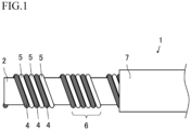
- a heater wire 1 of the present embodiment includes: a heat-emitting portion in which a heat-emitting wire is helically wound around an outer circumference of a fiber core 2; and a sheath 7 that is disposed around an outer circumference of the heat-emitting portion.
- the heat-emitting wire is formed by alternately winding a first heat-emitting wire 4 made of a first metal wire 4a and a second heat-emitting wire 5 provided with an insulating film 5b around an outer circumference of a second metal wire 5a.
- the same reference numerals will be assigned to members having the same function, and repeated description thereof may be omitted in some cases.
- the first heat-emitting wires 4 and the second heat-emitting wires 5 are alternately wound around the outer circumference of the fiber core 2.
- three first heat-emitting wires 4 and three second heat-emitting wires 5 are disposed.
- the first heat-emitting wire 4 and the first heat-emitting wire 4 are wound with a spacing.
- the second heat-emitting wire 5 and the second heat-emitting wire 5 are wound with a spacing.
- a collecting portion 6, in which the first heat-emitting wire 4 and the second heat-emitting wire 5 are in contact with each other, is disposed with a predetermined pitch.
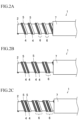
- the first heat-emitting wires 4 and the second heat-emitting wires 5 are alternately wound around the outer circumference of the fiber core 2.
- one first heat-emitting wire 4 and one second heat-emitting wire 5 are disposed.
- the first heat-emitting wire 4 and the first heat-emitting wire 4 are wound with a spacing.
- the second heat-emitting wire 5 and the second heat-emitting wire 5 are wound with a spacing.
- a collecting portion 6, in which the first heat-emitting wire 4 and the second heat-emitting wire 5 are in contact with each other, is disposed with a predetermined pitch.
- the first heat-emitting wires 4 and the second heat-emitting wires 5 are alternately wound around the outer circumference of the fiber core 2.
- two first heat-emitting wires 4 and one second heat-emitting wire 5 are disposed.
- the first heat-emitting wire 4 and the first heat-emitting wire 4 are wound with a spacing.
- the second heat-emitting wire 5 and the second heat-emitting wire 5 are wound with a spacing.
- a collecting portion 6, in which the first heat-emitting wire 4 and the second heat-emitting wire 5 are in contact with each other, is disposed with a predetermined pitch.
- the number of the first heat-emitting wires 4 may be one and the number of the second heat-emitting wires 5 may be two.
- the first heat-emitting wires 4 and the second heat-emitting wires 5 are alternately wound around the outer circumference of the fiber core 2.
- two first heat-emitting wires 4 and two second heat-emitting wires 5 are disposed.
- the first heat-emitting wire 4 and the first heat-emitting wire 4 are wound with a spacing.
- the second heat-emitting wire 5 and the second heat-emitting wire 5 are wound with a spacing.
- a collecting portion 6, in which the first heat-emitting wire 4 and the second heat-emitting wire 5 are in contact with each other, is disposed with a predetermined pitch.
- the predetermined pitch when the first heat-emitting wire 4 and the second heat-emitting wire 5 are helically wound is a pitch corresponding to a diameter of the fiber core 2 and the number and a diameter of the heat-emitting wires.
- the pitch when the wires are helically wound is in a range of 0.2 to 2.5 mm.
- first metal wire 4a and the second metal wire 5a are made of the same material and are set to have the same conductor diameter.
- the first metal wire 4a and the second metal wire 5a may be made of different materials and may be set to have different conductor diameters.
- the first metal wire 4a and the second metal wire 5a are copper wires or copper alloy wires.
- the copper alloy wire may include Cu-Ag alloy, Cu-Sn alloy, Cu-Ni alloy and the like.
- Solder plating, tin plating, gold plating, silver plating, nickel plating, or the like may be applied to surfaces of the metal wires.
- a practical total number of the first heat-emitting wires 4 and the second heat-emitting wires 5 is in a range of 2 to 10. Thereby, an axial length of the collecting portion 6 can be kept within a certain range, and favorable flexibility can be maintained. More preferably, the total number of the first heat-emitting wires 4 and the second heat-emitting wires 5 is in a range of 2 to 7.
- Conductor diameters of the first heat-emitting wire 4 and the second heat-emitting wire 5 are in a range of 0.03 to 0.2 mm. More preferably, the diameters are in a range of 0.03 to 0.15 mm. Thereby, it is possible to quickly warm the wires by using the collecting portion while sufficiently meeting the requirement for reduction in diameter, and it is possible to easily cope with wiring with a narrow pitch.
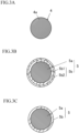
- the first heat-emitting wire 4 is made of the first metal wire 4a and does not have an insulating film.
- the insulating film is a non-metallic film such as a polymer compound, and the metal oxide film is not applied thereto.
- the second heat-emitting wire 5 is provided with an insulating film 5b around the outer circumference of the second metal wire 5a.
- the insulating film 5b employs a heat-resistant material, and is made of one or more of polyurethane, polyesterimide, polyimide, lubricating nylon, and lubricating polyamideimide.
- a thickness of the insulating film 5b is substantially specified in Japanese Industrial Standard (JIS C 3202:2014) Type 1, Type 2, or Type 3, and the thickness is appropriately selected in accordance with the application and size.
- the insulating film 5b is formed to have a desired thickness by a baking process.
- the insulating film 5b may have a multilayer structure in which polyurethane, polyesterimide, polyimide, or polyamideimide is used as a lower layer and lubricating nylon or lubricating polyamideimide is used as an upper layer.
- the polyurethane, polyesterimide, polyimide, or polyamideimide is subjected to the baking process by using the baking device, and subsequently overcoated with lubricating nylon or lubricating polyamideimide through, for example, one pass (coating is performed on the layer once, thereafter processed by heat treatment).
- a thickness of the lubricating nylon or lubricating polyamideimide is preferably in the range of 0.1 to 3 ⁇ m.
- Examples of lubricating nylon include nylon 66 and the like.
- Examples of lubricating polyamideimides include polyamideimides obtained by adding additives (for example, polyethylene, and the like) to polyamideimides to improve lubricity.
- Such lubricating nylon or lubricating polyamideimide causes lubricity on the surface of the second heat-emitting wire 5. As a result, even when the wire is repeatedly bent under loads, the wire is unlikely to be broken, and an increase in costs can be suppressed.
- the loads include loads at the time of manufacturing (for example, stress applied when the wire passes through a plurality of pulleys, stress concentration based on overlapping of the heat-emitting wires during winding, and the like), loads at the time of wiring (stress applied when the wire is bent and disposed, and the like), and loads at the time of installation (repeated stress at the time of seating in a case where the wire is used as a heater wire for seats, and the like). Since lubricating nylon or lubricating polyamideimide has low volatility such as liquid paraffin, the problem of volatilization does not occur. In addition, it is also possible to overcoat with silicone oil instead of lubricating nylon or lubricating polyamideimide.
- the thickness of the insulating film 5b is, for example, in a range of 0.1 to 3 ⁇ m.
- lubricating nylon include nylon 66 and the like.
- lubricating polyamideimides include polyamideimides obtained by adding additives (for example, polyethylene, and the like) to polyamideimides to improve lubricity.
- additives for example, polyethylene, and the like
- Such lubricating nylon or lubricating polyamideimide causes lubricity on the surface of the second heat-emitting wire 5. As a result, even when the wire is repeatedly bent under loads, the wire is unlikely to be broken, and an increase in costs can be suppressed.
- the loads include loads at the time of manufacturing (for example, stress applied when the wire passes through a plurality of pulleys, stress concentration based on overlapping of the heat-emitting wires during winding, and the like), loads at the time of wiring (stress applied when the wire is bent and disposed, and the like), and loads at the time of installation (repeated stress at the time of seating in a case where the wire is used as a heater wire for seats, and the like).
- loads at the time of manufacturing for example, stress applied when the wire passes through a plurality of pulleys, stress concentration based on overlapping of the heat-emitting wires during winding, and the like
- loads at the time of wiring stress applied when the wire is bent and disposed, and the like
- loads at the time of installation peerated stress at the time of seating in a case where the wire is used as a heater wire for seats, and the like.
- lubricating nylon or lubricating polyamideimide does not cause the problem of volatilization because liquid par
- a first insulating film 5b1 is formed around the outer circumference of the second metal wire 5a, and a second insulating film 5b2 made of a material different from the first insulating film 5b1 is formed around the outer circumference of the first insulating film 5b1.
- a single-layer insulating film 5b is formed around the outer circumference of the second metal wire 5a.
- the thickness of the insulating film 5b is in a range of 0.1 to 15 ⁇ m. By setting the thickness of the insulating film 5b in a range of 0.1 ⁇ m or more, the insulating property can be ensured.
- the insulating film 5b may have three or more layers in accordance with the application.
- the fiber core 2 has a function as a winding core, and is preferably a high tension body.
- the fiber core 2 is, for example, a fiber thread in which a plurality of fibers are bundled. It is preferable that the fibers constituting the fiber thread have a strength and a heat resistance required for the heater wire 1.
- Examples of fibers constituting the fiber thread may include polyester fibers such as Tetoron (registered trademark), wholly aromatic polyamide fibers such as Kevlar (registered trademark), polyarylate fibers such as Vectran (registered trademark), and glass fibers.
- the fiber core 2 may be a composite fiber obtained by combining fibers of different materials or fiber threads with different outer diameters.
- the fiber core 2 has a concentric (perfectly circular) or substantially concentric cross section by assembling, twisting, or braiding the fiber threads.
- the fiber core 2 has an outer diameter ranging from 0.1 to 1.0 mm. Thereby, favorable flexibility can be maintained, and the requirement for reduction in diameter can be sufficiently met. More preferably, the fiber core 2 has an outer diameter ranging from 0.1 to 0.4 mm.
- the fiber core 2 made of fiber thread is flexible and tends to be deformed.
- the outer diameter of the fiber core 2 is estimated as an outer diameter thereof in a case where the fiber core 2 is perfectly circular, and is estimated as an outer diameter, which is converted from the cross-sectional area to the cross-sectional area of a perfect circle, in a case where the fiber core 2 is flat.
- the fiber core 2 is generally defined by a denier (dtex), which indicates a weight of the fiber thread.
- 1 dtex is 1 g at a length of 10000 m.
- the range of dtex of the fiber core 2 is preferably a range of 110 to 2000 dtex.
- Such a fiber core 2 may be made of a single fiber thread, or may be made of two or more kinds of fiber threads. In a case where the fiber core 2 is constituted of two or more types of fiber threads, the total dtex may be within the above described range.
- 110 dtex or more a necessary durability can be ensured.
- 2000 dtex or less there is no particular problem with workability and processability.
- the sheath 7 is a sheath that covers the first heat-emitting wire 4 and the second heat-emitting wire 5.
- the first heat-emitting wire 4 and the second heat-emitting wire 5 can be disposed, and then formed by resin extrusion or the like so as to cover the outer circumferences of the heat-emitting wires.
- a constituent material of the sheath 7 is a resin material which has the insulating property and heat resistance. It is preferable that the sheath 7 is made of PVC (polyvinyl chloride), nylon, polyester elastomer, ETFE, FEP, or PFA fluorine-based resin.
- the sheath 7 can be made of polyolefin such as polyethylene or polyester such as polyethylene terephthalate.
- the thickness of the sheath 7 varies depending on the outer diameter dimension of the heat-emitting portion and the final outer diameter of the heater wire 1, but is preferably in a range of about 0.05 to 1.0 mm, and more preferably in a range of 0.10 to 0.30 mm.
- the heater wire 1 has an outer diameter ranging from 0.5 to 2.0 mm. More preferably, the heater wire 1 has an outer diameter ranging from 0.5 to 1.5 mm.
- the sheath 7 is formed by resin extrusion.
- the sheath 7 formed by the extrusion tends to have a constant thickness, and the unevenness of the surface thereof can be reduced.
- By providing such a sheath 7 formed by the extrusion as the outermost layer it is possible to have the effect of preventing local bending even in a case where the diameter is reduced for wiring with a narrow pitch.
- the heat-emitting element of the present embodiment is, for example, a seat heater, in which the heater wire 1 is disposed. Since the heater wire 1 has high flexibility, desired wiring can be easily performed by sewing the heater wire 1 to a seat body such as a seat base material constituting the heat-emitting element.
- the heat-emitting element of the present embodiment can be applied to heating products such as electric carpets and electric blankets, and heating members for vehicles such as seat heaters and steering heaters. It is preferable that the heat-emitting element can be attached to an automobile seat. In the case of the heat-emitting element as a heating member for automobiles, the heater wire 1 is sewn into an object such as a seat base material.
- the sewing of the heater wire 1 into the seat base material prevents the appearance of the heater wire 1 from being damaged by the influence of the volatile gas, and is unlikely to cause friction between the first heat-emitting wire 4 and the second heat-emitting wire 5 and the sheath 7. As a result, the sewing can be performed with favorable wiring.
- the heater wire 1 is wired and sewn, the structure is highly resistant to the stress applied to the heater wire 1. Therefore, the diameter can be reduced to the extent that there is no sense of incongruity at the time of sitting on the seat. Further, in a case of the heat-emitting element, the wiring with the narrow pitch becomes possible.
- a bundle of polyester threads having an outer diameter of 0.25 mm was used.
- a first metal wire 4a was used, which was obtained by drawing a copper-tin alloy wire (containing 0.3% by mass of tin) to have an outer diameter of 0.09 mm.
- a wire was used, in which a first insulating film 5b1 was formed around the outer circumference of the second metal wire 5a which is made by drawing a copper-tin alloy wire to have an outer diameter of 0.09 mm and a second insulating film 5b2 was formed around the outer circumference of the first insulating film 5b1.
- the first insulating film 5b1 was formed by baking and coating polyesterimide such that a thickness of polyesterimide is 10 ⁇ m.
- the second insulating film 5b2 was formed by applying lubricating polyamide such that a thickness of lubricating polyamide is 2 ⁇ m.
- On the fiber core 2, six heat-emitting wires were helically laterally wound at a pitch of 1.5 mm such that six heat-emitting wires formed a single layer all together.
- the heat-emitting wire is wound the first heat-emitting wire 4 and the second heat-emitting wire 5 alternately.
- the sheath 7 was formed by melting and extruding polyester such that the outer diameter of the heater wire 1 was 1.0 mm. In such a manner, the heater wire 1 was produced.
- a wire is used, which is formed by forming an insulating film 5b around the outer circumference of the second metal wire 5a which is made by drawing a copper-tin alloy wire to have an outer diameter of 0.09 mm.
- the insulating film 5b was formed by applying lubricating polyamide such that a thickness of the lubricating polyamide is 2 ⁇ m.
- the configuration other than the above described configuration is the same as Example 1.
- the first heat-emitting wire a wire was used, in which the first insulating film was formed around the outer circumference of the first metal wire which is made by drawing a copper-tin alloy wire to have an outer diameter of 0.09 mm and the second insulating film was formed around the outer circumference of the first insulating film.
- the first insulating film was formed by baking and coating polyesterimide such that a thickness of polyesterimide is 10 ⁇ m.
- the second insulating film was formed by applying lubricating polyamide such that a thickness of the lubricating polyamide is 2 ⁇ m.
- the configuration other than the above described configuration is the same as Example 1.
- Example 1 As the first heat-emitting wire, a first metal wire was used, which was obtained by drawing a copper-tin alloy wire to have an outer diameter of 0.09 mm. As the second heat-emitting wire, a second metal wire was used, which was obtained by drawing a copper-tin alloy wire to have an outer diameter of 0.09 mm.
- the configuration other than the above described configuration is the same as Example 1.
- a heater wire having a length of 1000 mm produced in each of the examples and the comparative example was interposed between mandrels 42, 42 having a radius of 5 mm, and a load 41 was attached to the lower end portion of the heater wire, and the number of times of bending was measured by bending each side by 90 degrees, at a speed of 30 times per minute, in a direction perpendicular to the mandrel 42.
- the flexibility thereof was evaluated by the number of times until all the first metal wires and the second metal wires were broken.
- Table 1 shows evaluation results of samples.
- Example 1 Example 2 Reference Example Comparative Example Countermeasure against local heat emission O O O X Bending test result 40,000 times 37,000 times 40,000 times 35,000 times
- Example 1 the number of times of bending of each of the heater wires 1 of Examples 1 and 2 was 37,000 times or more. In contrast, in the comparative example, the number of times of bending remained at 35,000 times. In particular, in Example 1, the number of times of bending reached 40,000 times, which is equivalent to that of Reference Example.
- all the heat-emitting wires are enamelled wires. Therefore, the production lead time is long, and the material costs and the like increase.
- all of the heat-emitting wires are bare conductor wires, and no countermeasure against local heat emission is implemented. Therefore, the operational durability is inferior.
Landscapes
- Physics & Mathematics (AREA)
- Spectroscopy & Molecular Physics (AREA)
- Resistance Heating (AREA)
Applications Claiming Priority (2)
| Application Number | Priority Date | Filing Date | Title |
|---|---|---|---|
| JP2021118390A JP2023014457A (ja) | 2021-07-19 | 2021-07-19 | ヒータ線、及び発熱体 |
| PCT/JP2021/032375 WO2023002638A1 (ja) | 2021-07-19 | 2021-09-03 | ヒータ線、及び発熱体 |
Publications (2)
| Publication Number | Publication Date |
|---|---|
| EP4290979A1 true EP4290979A1 (de) | 2023-12-13 |
| EP4290979A4 EP4290979A4 (de) | 2024-12-18 |
Family
ID=84979049
Family Applications (1)
| Application Number | Title | Priority Date | Filing Date |
|---|---|---|---|
| EP21950988.2A Pending EP4290979A4 (de) | 2021-07-19 | 2021-09-03 | Heizdraht und wärmeemittierendes element |
Country Status (5)
| Country | Link |
|---|---|
| US (1) | US20240080944A1 (de) |
| EP (1) | EP4290979A4 (de) |
| JP (1) | JP2023014457A (de) |
| CN (1) | CN117121633A (de) |
| WO (1) | WO2023002638A1 (de) |
Family Cites Families (7)
| Publication number | Priority date | Publication date | Assignee | Title |
|---|---|---|---|---|
| JPS6147087A (ja) | 1984-08-11 | 1986-03-07 | 松下電器産業株式会社 | シ−トヒ−タの発熱線 |
| US20080047733A1 (en) * | 2006-08-25 | 2008-02-28 | W.E.T. Automotive Systems Ag | Spiral heating wire |
| JP5561589B2 (ja) * | 2009-03-13 | 2014-07-30 | 日立金属株式会社 | 絶縁塗料及び絶縁電線、並びにそれを用いたコイル |
| JP2013020951A (ja) * | 2011-06-14 | 2013-01-31 | Kurabe Industrial Co Ltd | コード状ヒータと面状ヒータ |
| JP6320935B2 (ja) * | 2012-12-25 | 2018-05-09 | 株式会社クラベ | コード状ヒータと面状ヒータ |
| CN105900183A (zh) * | 2014-09-05 | 2016-08-24 | 日立金属株式会社 | 绝缘电线及绕线 |
| US11457512B2 (en) * | 2017-07-26 | 2022-09-27 | Kurabe Industrial Co., Ltd. | Cord-shaped heater, sheet-shaped heater and manufacturing method of sheet-shaped heater |
-
2021
- 2021-07-19 JP JP2021118390A patent/JP2023014457A/ja active Pending
- 2021-09-03 CN CN202180096529.6A patent/CN117121633A/zh active Pending
- 2021-09-03 EP EP21950988.2A patent/EP4290979A4/de active Pending
- 2021-09-03 US US18/280,387 patent/US20240080944A1/en active Pending
- 2021-09-03 WO PCT/JP2021/032375 patent/WO2023002638A1/ja not_active Ceased
Also Published As
| Publication number | Publication date |
|---|---|
| US20240080944A1 (en) | 2024-03-07 |
| JP2023014457A (ja) | 2023-01-31 |
| CN117121633A (zh) | 2023-11-24 |
| WO2023002638A1 (ja) | 2023-01-26 |
| EP4290979A4 (de) | 2024-12-18 |
Similar Documents
| Publication | Publication Date | Title |
|---|---|---|
| US8450667B2 (en) | Flexible, electrically heatable hose | |
| EP2300648B1 (de) | Mehrfachbündelgarn mit verminderten torsionen | |
| US10340058B2 (en) | Cable with braided shield | |
| JP6783550B2 (ja) | 高屈曲ヒータ線及び面状発熱体 | |
| US20080047733A1 (en) | Spiral heating wire | |
| CN103765984A (zh) | 包括具有金属丝的加热线缆的车辆座椅加热元件 | |
| EP4290979A1 (de) | Heizdraht und wärmeemittierendes element | |
| US5354954A (en) | Dielectric miniature electric cable | |
| JP7537911B2 (ja) | 難燃性に優れた高屈曲ヒータ線及び発熱体 | |
| JP7010249B2 (ja) | 導体および電源ケーブル | |
| JP2022017006A (ja) | 耐湿熱ヒータ線用発熱線、耐湿熱ヒータ線及び発熱体 | |
| CN115996493A (zh) | 高弯曲加热线和放热体 | |
| JP7412127B2 (ja) | 耐屈曲絶縁電線 | |
| JP2021190172A (ja) | 高屈曲ヒータ線及び発熱体 | |
| JP2021190169A (ja) | 高屈曲ヒータ線及び発熱体 | |
| EP4115706B1 (de) | Heizleiterdrahtähnliches element | |
| JP7486300B2 (ja) | 耐屈曲絶縁電線 | |
| CN115996492A (zh) | 高弯曲加热线和放热体 | |
| JP2021190171A (ja) | 高屈曲ヒータ線及び発熱体 | |
| JP7412126B2 (ja) | 耐屈曲絶縁電線 | |
| JP7524692B2 (ja) | 複合ケーブル | |
| JP7731711B2 (ja) | 多芯ケーブル | |
| EP2797383A1 (de) | Heizkabel | |
| CN115996490A (zh) | 高弯曲加热线和放热体 | |
| JP7412125B2 (ja) | 耐屈曲絶縁電線 |
Legal Events
| Date | Code | Title | Description |
|---|---|---|---|
| STAA | Information on the status of an ep patent application or granted ep patent |
Free format text: STATUS: THE INTERNATIONAL PUBLICATION HAS BEEN MADE |
|
| PUAI | Public reference made under article 153(3) epc to a published international application that has entered the european phase |
Free format text: ORIGINAL CODE: 0009012 |
|
| STAA | Information on the status of an ep patent application or granted ep patent |
Free format text: STATUS: REQUEST FOR EXAMINATION WAS MADE |
|
| 17P | Request for examination filed |
Effective date: 20230906 |
|
| AK | Designated contracting states |
Kind code of ref document: A1 Designated state(s): AL AT BE BG CH CY CZ DE DK EE ES FI FR GB GR HR HU IE IS IT LI LT LU LV MC MK MT NL NO PL PT RO RS SE SI SK SM TR |
|
| DAV | Request for validation of the european patent (deleted) | ||
| DAX | Request for extension of the european patent (deleted) | ||
| A4 | Supplementary search report drawn up and despatched |
Effective date: 20241114 |
|
| RIC1 | Information provided on ipc code assigned before grant |
Ipc: H05B 3/56 20060101AFI20241108BHEP |