EP4290674A1 - Electrode assembly, secondary battery, battery pack and automobile comprising same - Google Patents
Electrode assembly, secondary battery, battery pack and automobile comprising same Download PDFInfo
- Publication number
- EP4290674A1 EP4290674A1 EP22853395.6A EP22853395A EP4290674A1 EP 4290674 A1 EP4290674 A1 EP 4290674A1 EP 22853395 A EP22853395 A EP 22853395A EP 4290674 A1 EP4290674 A1 EP 4290674A1
- Authority
- EP
- European Patent Office
- Prior art keywords
- electrode
- electrode assembly
- current collector
- segment pieces
- assembly according
- Prior art date
- Legal status (The legal status is an assumption and is not a legal conclusion. Google has not performed a legal analysis and makes no representation as to the accuracy of the status listed.)
- Pending
Links
- 238000004804 winding Methods 0.000 claims abstract description 93
- 238000003466 welding Methods 0.000 claims description 67
- 238000007789 sealing Methods 0.000 claims description 20
- 238000005452 bending Methods 0.000 description 34
- 238000005520 cutting process Methods 0.000 description 26
- 239000010410 layer Substances 0.000 description 26
- 238000000034 method Methods 0.000 description 26
- 230000008569 process Effects 0.000 description 25
- 239000011149 active material Substances 0.000 description 20
- XEEYBQQBJWHFJM-UHFFFAOYSA-N iron Substances [Fe] XEEYBQQBJWHFJM-UHFFFAOYSA-N 0.000 description 18
- 239000003792 electrolyte Substances 0.000 description 13
- 229910052751 metal Inorganic materials 0.000 description 12
- 239000002184 metal Substances 0.000 description 12
- 230000004048 modification Effects 0.000 description 12
- 238000012986 modification Methods 0.000 description 12
- 238000004088 simulation Methods 0.000 description 12
- 229910052742 iron Inorganic materials 0.000 description 11
- 229910052782 aluminium Inorganic materials 0.000 description 10
- 230000007423 decrease Effects 0.000 description 10
- 239000011888 foil Substances 0.000 description 10
- 230000000052 comparative effect Effects 0.000 description 9
- 238000009429 electrical wiring Methods 0.000 description 8
- 230000020169 heat generation Effects 0.000 description 8
- 239000012212 insulator Substances 0.000 description 8
- 239000011247 coating layer Substances 0.000 description 7
- 238000004519 manufacturing process Methods 0.000 description 7
- 239000000463 material Substances 0.000 description 7
- -1 polyethylene terephthalate Polymers 0.000 description 7
- 239000007774 positive electrode material Substances 0.000 description 7
- XAGFODPZIPBFFR-UHFFFAOYSA-N aluminium Chemical compound [Al] XAGFODPZIPBFFR-UHFFFAOYSA-N 0.000 description 6
- 238000013461 design Methods 0.000 description 6
- 238000002347 injection Methods 0.000 description 6
- 239000007924 injection Substances 0.000 description 6
- PXHVJJICTQNCMI-UHFFFAOYSA-N nickel Substances [Ni] PXHVJJICTQNCMI-UHFFFAOYSA-N 0.000 description 6
- 229910052710 silicon Inorganic materials 0.000 description 6
- 230000008901 benefit Effects 0.000 description 5
- 238000002788 crimping Methods 0.000 description 5
- 230000000694 effects Effects 0.000 description 5
- 238000009413 insulation Methods 0.000 description 5
- 229910052744 lithium Inorganic materials 0.000 description 5
- 229910052750 molybdenum Inorganic materials 0.000 description 5
- 239000007773 negative electrode material Substances 0.000 description 5
- 229910052720 vanadium Inorganic materials 0.000 description 5
- VGGSQFUCUMXWEO-UHFFFAOYSA-N Ethene Chemical compound C=C VGGSQFUCUMXWEO-UHFFFAOYSA-N 0.000 description 4
- 239000005977 Ethylene Substances 0.000 description 4
- GWEVSGVZZGPLCZ-UHFFFAOYSA-N Titan oxide Chemical compound O=[Ti]=O GWEVSGVZZGPLCZ-UHFFFAOYSA-N 0.000 description 4
- 230000008859 change Effects 0.000 description 4
- 229910052804 chromium Inorganic materials 0.000 description 4
- 229910052802 copper Inorganic materials 0.000 description 4
- 239000010949 copper Substances 0.000 description 4
- 238000007599 discharging Methods 0.000 description 4
- 239000010954 inorganic particle Substances 0.000 description 4
- 229910052749 magnesium Inorganic materials 0.000 description 4
- 229910052748 manganese Inorganic materials 0.000 description 4
- 229910052759 nickel Inorganic materials 0.000 description 4
- XOLBLPGZBRYERU-UHFFFAOYSA-N tin dioxide Chemical compound O=[Sn]=O XOLBLPGZBRYERU-UHFFFAOYSA-N 0.000 description 4
- 229910052719 titanium Inorganic materials 0.000 description 4
- OKTJSMMVPCPJKN-UHFFFAOYSA-N Carbon Chemical compound [C] OKTJSMMVPCPJKN-UHFFFAOYSA-N 0.000 description 3
- RYGMFSIKBFXOCR-UHFFFAOYSA-N Copper Chemical compound [Cu] RYGMFSIKBFXOCR-UHFFFAOYSA-N 0.000 description 3
- 230000002159 abnormal effect Effects 0.000 description 3
- 230000015572 biosynthetic process Effects 0.000 description 3
- 150000001768 cations Chemical class 0.000 description 3
- 238000001816 cooling Methods 0.000 description 3
- 229920001577 copolymer Polymers 0.000 description 3
- 238000011156 evaluation Methods 0.000 description 3
- 230000001747 exhibiting effect Effects 0.000 description 3
- 239000007769 metal material Substances 0.000 description 3
- 230000003647 oxidation Effects 0.000 description 3
- 238000007254 oxidation reaction Methods 0.000 description 3
- 238000012545 processing Methods 0.000 description 3
- 238000006479 redox reaction Methods 0.000 description 3
- ODINCKMPIJJUCX-UHFFFAOYSA-N Calcium oxide Chemical compound [Ca]=O ODINCKMPIJJUCX-UHFFFAOYSA-N 0.000 description 2
- KMTRUDSVKNLOMY-UHFFFAOYSA-N Ethylene carbonate Chemical compound O=C1OCCO1 KMTRUDSVKNLOMY-UHFFFAOYSA-N 0.000 description 2
- CPLXHLVBOLITMK-UHFFFAOYSA-N Magnesium oxide Chemical compound [Mg]=O CPLXHLVBOLITMK-UHFFFAOYSA-N 0.000 description 2
- 229910052779 Neodymium Inorganic materials 0.000 description 2
- 239000004743 Polypropylene Substances 0.000 description 2
- XLOMVQKBTHCTTD-UHFFFAOYSA-N Zinc monoxide Chemical compound [Zn]=O XLOMVQKBTHCTTD-UHFFFAOYSA-N 0.000 description 2
- MCMNRKCIXSYSNV-UHFFFAOYSA-N Zirconium dioxide Chemical compound O=[Zr]=O MCMNRKCIXSYSNV-UHFFFAOYSA-N 0.000 description 2
- 150000001339 alkali metal compounds Chemical class 0.000 description 2
- PNEYBMLMFCGWSK-UHFFFAOYSA-N aluminium oxide Inorganic materials [O-2].[O-2].[O-2].[Al+3].[Al+3] PNEYBMLMFCGWSK-UHFFFAOYSA-N 0.000 description 2
- 229910052799 carbon Inorganic materials 0.000 description 2
- 239000003575 carbonaceous material Substances 0.000 description 2
- 239000002131 composite material Substances 0.000 description 2
- 150000001875 compounds Chemical class 0.000 description 2
- 229910052593 corundum Inorganic materials 0.000 description 2
- 230000003247 decreasing effect Effects 0.000 description 2
- 238000010586 diagram Methods 0.000 description 2
- 238000009826 distribution Methods 0.000 description 2
- JBTWLSYIZRCDFO-UHFFFAOYSA-N ethyl methyl carbonate Chemical compound CCOC(=O)OC JBTWLSYIZRCDFO-UHFFFAOYSA-N 0.000 description 2
- 238000002474 experimental method Methods 0.000 description 2
- 230000007935 neutral effect Effects 0.000 description 2
- 239000002245 particle Substances 0.000 description 2
- 230000000704 physical effect Effects 0.000 description 2
- 229920001707 polybutylene terephthalate Polymers 0.000 description 2
- 229920006254 polymer film Polymers 0.000 description 2
- 239000002952 polymeric resin Substances 0.000 description 2
- 229920000098 polyolefin Polymers 0.000 description 2
- 229920001155 polypropylene Polymers 0.000 description 2
- 239000011164 primary particle Substances 0.000 description 2
- 238000006722 reduction reaction Methods 0.000 description 2
- 238000000926 separation method Methods 0.000 description 2
- 239000000243 solution Substances 0.000 description 2
- 239000000126 substance Substances 0.000 description 2
- 229920003002 synthetic resin Polymers 0.000 description 2
- 229910001845 yogo sapphire Inorganic materials 0.000 description 2
- 229910052726 zirconium Inorganic materials 0.000 description 2
- 229910000838 Al alloy Inorganic materials 0.000 description 1
- 101100317222 Borrelia hermsii vsp3 gene Proteins 0.000 description 1
- 229910000881 Cu alloy Inorganic materials 0.000 description 1
- 229910000570 Cupronickel Inorganic materials 0.000 description 1
- 229910009939 Li2M2O3 Inorganic materials 0.000 description 1
- 229910012682 Li3M2(PO4)3 Inorganic materials 0.000 description 1
- 229910011104 LiM1 Inorganic materials 0.000 description 1
- 229910001290 LiPF6 Inorganic materials 0.000 description 1
- 229910010187 LiaM1xFe1-xM2yP1-yM3zO4-z Inorganic materials 0.000 description 1
- 229910010190 LiaM1xFe1-xM2yP1-yM3zO4−z Inorganic materials 0.000 description 1
- 229910010183 LiaM1xFe1−xM2yP1−yM3zO4−z Inorganic materials 0.000 description 1
- WHXSMMKQMYFTQS-UHFFFAOYSA-N Lithium Chemical compound [Li] WHXSMMKQMYFTQS-UHFFFAOYSA-N 0.000 description 1
- 229910000990 Ni alloy Inorganic materials 0.000 description 1
- 229910020213 PB(Mg3Nb2/3)O3-PbTiO3 Inorganic materials 0.000 description 1
- 229910019142 PO4 Inorganic materials 0.000 description 1
- 229910020210 Pb(Mg3Nb2/3)O3—PbTiO3 Inorganic materials 0.000 description 1
- 229910020294 Pb(Zr,Ti)O3 Inorganic materials 0.000 description 1
- 229910020351 Pb1-xLaxZr1-yTiyO3 Inorganic materials 0.000 description 1
- 229910020345 Pb1−xLaxZr1−yTiyO3 Inorganic materials 0.000 description 1
- 229910002370 SrTiO3 Inorganic materials 0.000 description 1
- ATJFFYVFTNAWJD-UHFFFAOYSA-N Tin Chemical compound [Sn] ATJFFYVFTNAWJD-UHFFFAOYSA-N 0.000 description 1
- 230000005856 abnormality Effects 0.000 description 1
- 229910052787 antimony Inorganic materials 0.000 description 1
- 229910052785 arsenic Inorganic materials 0.000 description 1
- 229910002113 barium titanate Inorganic materials 0.000 description 1
- 239000011230 binding agent Substances 0.000 description 1
- 230000000903 blocking effect Effects 0.000 description 1
- IAQRGUVFOMOMEM-UHFFFAOYSA-N butene Natural products CC=CC IAQRGUVFOMOMEM-UHFFFAOYSA-N 0.000 description 1
- 239000006227 byproduct Substances 0.000 description 1
- 229910052791 calcium Inorganic materials 0.000 description 1
- CETPSERCERDGAM-UHFFFAOYSA-N ceric oxide Chemical compound O=[Ce]=O CETPSERCERDGAM-UHFFFAOYSA-N 0.000 description 1
- 229910000422 cerium(IV) oxide Inorganic materials 0.000 description 1
- 238000006243 chemical reaction Methods 0.000 description 1
- IEJIGPNLZYLLBP-UHFFFAOYSA-N dimethyl carbonate Chemical compound COC(=O)OC IEJIGPNLZYLLBP-UHFFFAOYSA-N 0.000 description 1
- 238000010292 electrical insulation Methods 0.000 description 1
- 238000010294 electrolyte impregnation Methods 0.000 description 1
- 238000006056 electrooxidation reaction Methods 0.000 description 1
- 238000005516 engineering process Methods 0.000 description 1
- 238000004880 explosion Methods 0.000 description 1
- 239000000835 fiber Substances 0.000 description 1
- 239000002803 fossil fuel Substances 0.000 description 1
- 229910052732 germanium Inorganic materials 0.000 description 1
- 239000003365 glass fiber Substances 0.000 description 1
- 239000010439 graphite Substances 0.000 description 1
- 229910002804 graphite Inorganic materials 0.000 description 1
- CJNBYAVZURUTKZ-UHFFFAOYSA-N hafnium(iv) oxide Chemical compound O=[Hf]=O CJNBYAVZURUTKZ-UHFFFAOYSA-N 0.000 description 1
- 229910052736 halogen Inorganic materials 0.000 description 1
- 150000002367 halogens Chemical class 0.000 description 1
- 229920001519 homopolymer Polymers 0.000 description 1
- 230000006872 improvement Effects 0.000 description 1
- 238000001746 injection moulding Methods 0.000 description 1
- 239000011256 inorganic filler Substances 0.000 description 1
- 229910003475 inorganic filler Inorganic materials 0.000 description 1
- 229910010272 inorganic material Inorganic materials 0.000 description 1
- 239000011147 inorganic material Substances 0.000 description 1
- 238000011900 installation process Methods 0.000 description 1
- 230000001788 irregular Effects 0.000 description 1
- 238000012423 maintenance Methods 0.000 description 1
- 230000014759 maintenance of location Effects 0.000 description 1
- 238000002844 melting Methods 0.000 description 1
- 230000008018 melting Effects 0.000 description 1
- 150000002736 metal compounds Chemical class 0.000 description 1
- 229910044991 metal oxide Inorganic materials 0.000 description 1
- 150000004706 metal oxides Chemical class 0.000 description 1
- 230000001151 other effect Effects 0.000 description 1
- NBIIXXVUZAFLBC-UHFFFAOYSA-K phosphate Chemical compound [O-]P([O-])([O-])=O NBIIXXVUZAFLBC-UHFFFAOYSA-K 0.000 description 1
- 239000010452 phosphate Substances 0.000 description 1
- 229920000139 polyethylene terephthalate Polymers 0.000 description 1
- 239000005020 polyethylene terephthalate Substances 0.000 description 1
- 229920000642 polymer Polymers 0.000 description 1
- 229910052700 potassium Inorganic materials 0.000 description 1
- 238000003825 pressing Methods 0.000 description 1
- 239000000047 product Substances 0.000 description 1
- 229920001384 propylene homopolymer Polymers 0.000 description 1
- 238000004080 punching Methods 0.000 description 1
- 230000003252 repetitive effect Effects 0.000 description 1
- 229920005989 resin Polymers 0.000 description 1
- 239000011347 resin Substances 0.000 description 1
- 229910052707 ruthenium Inorganic materials 0.000 description 1
- 239000000523 sample Substances 0.000 description 1
- 229910052706 scandium Inorganic materials 0.000 description 1
- 239000011163 secondary particle Substances 0.000 description 1
- 239000010703 silicon Substances 0.000 description 1
- 150000003377 silicon compounds Chemical class 0.000 description 1
- 229910052708 sodium Inorganic materials 0.000 description 1
- 239000002904 solvent Substances 0.000 description 1
- 239000010935 stainless steel Substances 0.000 description 1
- 229910001220 stainless steel Inorganic materials 0.000 description 1
- 229910052717 sulfur Inorganic materials 0.000 description 1
- 150000003606 tin compounds Chemical class 0.000 description 1
- 229910000314 transition metal oxide Inorganic materials 0.000 description 1
- RUDFQVOCFDJEEF-UHFFFAOYSA-N yttrium(III) oxide Inorganic materials [O-2].[O-2].[O-2].[Y+3].[Y+3] RUDFQVOCFDJEEF-UHFFFAOYSA-N 0.000 description 1
- 229910052725 zinc Inorganic materials 0.000 description 1
Images


Classifications
-
- H—ELECTRICITY
- H01—ELECTRIC ELEMENTS
- H01M—PROCESSES OR MEANS, e.g. BATTERIES, FOR THE DIRECT CONVERSION OF CHEMICAL ENERGY INTO ELECTRICAL ENERGY
- H01M10/00—Secondary cells; Manufacture thereof
- H01M10/04—Construction or manufacture in general
- H01M10/0431—Cells with wound or folded electrodes
-
- H—ELECTRICITY
- H01—ELECTRIC ELEMENTS
- H01M—PROCESSES OR MEANS, e.g. BATTERIES, FOR THE DIRECT CONVERSION OF CHEMICAL ENERGY INTO ELECTRICAL ENERGY
- H01M10/00—Secondary cells; Manufacture thereof
- H01M10/05—Accumulators with non-aqueous electrolyte
- H01M10/058—Construction or manufacture
- H01M10/0587—Construction or manufacture of accumulators having only wound construction elements, i.e. wound positive electrodes, wound negative electrodes and wound separators
-
- H—ELECTRICITY
- H01—ELECTRIC ELEMENTS
- H01M—PROCESSES OR MEANS, e.g. BATTERIES, FOR THE DIRECT CONVERSION OF CHEMICAL ENERGY INTO ELECTRICAL ENERGY
- H01M50/00—Constructional details or processes of manufacture of the non-active parts of electrochemical cells other than fuel cells, e.g. hybrid cells
- H01M50/10—Primary casings; Jackets or wrappings
- H01M50/102—Primary casings; Jackets or wrappings characterised by their shape or physical structure
- H01M50/107—Primary casings; Jackets or wrappings characterised by their shape or physical structure having curved cross-section, e.g. round or elliptic
-
- H—ELECTRICITY
- H01—ELECTRIC ELEMENTS
- H01M—PROCESSES OR MEANS, e.g. BATTERIES, FOR THE DIRECT CONVERSION OF CHEMICAL ENERGY INTO ELECTRICAL ENERGY
- H01M50/00—Constructional details or processes of manufacture of the non-active parts of electrochemical cells other than fuel cells, e.g. hybrid cells
- H01M50/50—Current conducting connections for cells or batteries
- H01M50/531—Electrode connections inside a battery casing
- H01M50/534—Electrode connections inside a battery casing characterised by the material of the leads or tabs
-
- H—ELECTRICITY
- H01—ELECTRIC ELEMENTS
- H01M—PROCESSES OR MEANS, e.g. BATTERIES, FOR THE DIRECT CONVERSION OF CHEMICAL ENERGY INTO ELECTRICAL ENERGY
- H01M50/00—Constructional details or processes of manufacture of the non-active parts of electrochemical cells other than fuel cells, e.g. hybrid cells
- H01M50/50—Current conducting connections for cells or batteries
- H01M50/531—Electrode connections inside a battery casing
- H01M50/538—Connection of several leads or tabs of wound or folded electrode stacks
-
- H—ELECTRICITY
- H01—ELECTRIC ELEMENTS
- H01M—PROCESSES OR MEANS, e.g. BATTERIES, FOR THE DIRECT CONVERSION OF CHEMICAL ENERGY INTO ELECTRICAL ENERGY
- H01M50/00—Constructional details or processes of manufacture of the non-active parts of electrochemical cells other than fuel cells, e.g. hybrid cells
- H01M50/50—Current conducting connections for cells or batteries
- H01M50/543—Terminals
- H01M50/564—Terminals characterised by their manufacturing process
- H01M50/566—Terminals characterised by their manufacturing process by welding, soldering or brazing
-
- H—ELECTRICITY
- H01—ELECTRIC ELEMENTS
- H01M—PROCESSES OR MEANS, e.g. BATTERIES, FOR THE DIRECT CONVERSION OF CHEMICAL ENERGY INTO ELECTRICAL ENERGY
- H01M2220/00—Batteries for particular applications
- H01M2220/20—Batteries in motive systems, e.g. vehicle, ship, plane
-
- H—ELECTRICITY
- H01—ELECTRIC ELEMENTS
- H01M—PROCESSES OR MEANS, e.g. BATTERIES, FOR THE DIRECT CONVERSION OF CHEMICAL ENERGY INTO ELECTRICAL ENERGY
- H01M50/00—Constructional details or processes of manufacture of the non-active parts of electrochemical cells other than fuel cells, e.g. hybrid cells
- H01M50/50—Current conducting connections for cells or batteries
- H01M50/531—Electrode connections inside a battery casing
- H01M50/536—Electrode connections inside a battery casing characterised by the method of fixing the leads to the electrodes, e.g. by welding
-
- Y—GENERAL TAGGING OF NEW TECHNOLOGICAL DEVELOPMENTS; GENERAL TAGGING OF CROSS-SECTIONAL TECHNOLOGIES SPANNING OVER SEVERAL SECTIONS OF THE IPC; TECHNICAL SUBJECTS COVERED BY FORMER USPC CROSS-REFERENCE ART COLLECTIONS [XRACs] AND DIGESTS
- Y02—TECHNOLOGIES OR APPLICATIONS FOR MITIGATION OR ADAPTATION AGAINST CLIMATE CHANGE
- Y02E—REDUCTION OF GREENHOUSE GAS [GHG] EMISSIONS, RELATED TO ENERGY GENERATION, TRANSMISSION OR DISTRIBUTION
- Y02E60/00—Enabling technologies; Technologies with a potential or indirect contribution to GHG emissions mitigation
- Y02E60/10—Energy storage using batteries
-
- Y—GENERAL TAGGING OF NEW TECHNOLOGICAL DEVELOPMENTS; GENERAL TAGGING OF CROSS-SECTIONAL TECHNOLOGIES SPANNING OVER SEVERAL SECTIONS OF THE IPC; TECHNICAL SUBJECTS COVERED BY FORMER USPC CROSS-REFERENCE ART COLLECTIONS [XRACs] AND DIGESTS
- Y02—TECHNOLOGIES OR APPLICATIONS FOR MITIGATION OR ADAPTATION AGAINST CLIMATE CHANGE
- Y02P—CLIMATE CHANGE MITIGATION TECHNOLOGIES IN THE PRODUCTION OR PROCESSING OF GOODS
- Y02P70/00—Climate change mitigation technologies in the production process for final industrial or consumer products
- Y02P70/50—Manufacturing or production processes characterised by the final manufactured product
Definitions
- the present disclosure relates to an electrode assembly, a secondary battery, a battery pack and a vehicle including the same, and more specifically, to a jelly-roll type electrode assembly capable of implementing low resistance, a cylindrical secondary battery including the same, a battery pack and a vehicle including the same.
- the present application claims priority to Korean Patent Application Nos. 10-2021-0103378 and 10-2022-0089230 filed on August 5, 2021 and July 19, 2022, respectively, in the Republic of Korea, the disclosures of which are incorporated herein by reference.
- Secondary batteries have high applicability according to product groups and electrical characteristics such as high energy density, and thus are commonly applied not only to portable devices but also to electric vehicles (EVs) or hybrid electric vehicles (HEVs) driven by electric power sources.
- EVs electric vehicles
- HEVs hybrid electric vehicles
- Such a secondary battery is attracting attention as a new energy source to improve eco-friendliness and energy efficiency in that it has not only a primary advantage of dramatically reducing the use of fossil fuels, but also no byproducts generated from the use of energy.
- cylindrical, prismatic, and pouch-type second batteries are known.
- a separator that is an insulator is disposed between a positive electrode and a negative electrode and wound to form a jelly-roll type electrode assembly, and a battery is formed by inserting the resultant electrode assembly into a battery can.
- an electrode tab having a strip shape may be connected to an uncoated portion of each of the positive electrode and the negative electrode, and the electrode tab electrically connects the electrode assembly and an electrode terminal exposed to the outside.
- the capacity may be increased by increasing cell size.
- FIG. 1 is a view illustrating a state in which a positive electrode and a negative electrode applied to a conventional cylindrical secondary battery are spread out.
- FIG. 1 as electrodes applied to a conventional cylindrical secondary battery, a positive electrode 1 and a negative electrode 2 are illustrated.
- a strip-shaped positive electrode tab 1b is connected to an uncoated portion 1a formed in the middle portion of the positive electrode 1 in the lengthwise direction to protrude upward along the widthwise direction
- a strip-shaped negative electrode tab 2b is connected to an uncoated portion 2a formed at both ends of the negative electrode 2 in the lengthwise direction to protrude downward along the widthwise direction.
- FIG. 1 (a) there are one positive electrode tab 1b and one negative electrode tab 2b, respectively, and in FIG. 1(b) , there are one positive electrode tab 1b and two negative electrode tabs 2b.
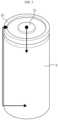
- FIG. 2 is a view schematically illustrating the flow of current or electrons outside a secondary battery in a conventional cylindrical secondary battery.
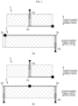
- FIG. 3 is a view schematically illustrating the flow of current or electrons in a positive electrode and a negative electrode constituting an electrode assembly in a conventional cylindrical secondary battery.
- the current path may be largely divided into two paths, that is, a path from the module bus bar welding position to the electrode tabs 1b, 2b of each electrode 1, 2 (hereinafter, a first path), and the other path from the electrode tabs 1b, 2b of each electrode 1, 2 to the end point of the electrode.
- a first path is illustrated in FIG. 2 , in which current starting points (marked with a circle) are located at a positive electrode terminal 1c and a negative electrode terminal 2c.
- the positive electrode terminal 1c is a cap of a sealing body that seals an opening of the battery can 3, and the negative electrode terminal 2c is the battery can 3.
- a case where the module bus bar welding position is located at the top of the cylindrical secondary battery is taken as an example.
- a current path starting from the positive electrode terminal 1c and connected to the positive electrode tab 1b is formed, and a current path starting from the negative electrode terminal 2c and connected to the negative electrode tab 2b is formed (a connection position is marked with a triangle). In this way, the first path is determined by the cell appearance.
- the maximum current path of the electrode is determined depending on the geometry of the current collector (foil) constituting the electrode and the position and number of electrode tabs.
- the maximum current path of the electrode may be defined as the longest distance between an electrode point farthest from the electrode tab and the electrode tab.
- the maximum current path uniquely determined according to the geometry of the electrode and the number and position of electrode tabs is referred to as a second path of the electrode.
- the second path that is the maximum current path of the electrode is illustrated, wherein the length of the second path varies according to the formation position and number of the electrode tabs 1b, 2b.
- the second path (maximum current path) of the positive electrode 1 includes a widthwise direction current path starting from the positive electrode terminal 1c of FIG. 2 and extending along the positive electrode tab 1b inside the cylindrical secondary battery, and a lengthwise direction current path traversing in the lengthwise direction of the positive electrode 1 and ending at the lower right of the positive electrode 1 (an electrode point farthest from the electrode tab is marked with a square).
- the second path (maximum current path) of the negative electrode 2 includes a widthwise direction current path starting from the negative electrode terminal 2c of FIG. 2 and extending along the negative electrode tab 2b inside the cylindrical secondary battery, and a lengthwise direction current path traversing in the lengthwise direction of the negative electrode 2 and ending at the upper left of the negative electrode 2.
- the second path of the positive electrode 1 is the same as that of FIG. 3 (a) .
- the second path (maximum current path) of the negative electrode 2 is reduced by 1/2 in the lengthwise direction current path, and thus is shorter than that of FIG. 3 (a) .
- the second path decreases by that amount due to a decrease in the lengthwise direction current path.
- the form factor means a value indicating the diameter and height of the cylindrical secondary battery.
- the first two numbers represent the diameter of the cell, and the remaining numbers represent the height of the cell.
- the lengthwise direction current path is very long compared to the widthwise direction current path.
- the resistance of the battery increases as the current path lengthens.
- the increase in the number of negative electrode tabs 2b shown in FIG. 3 (b) is also to decrease the resistance of the negative electrode by reducing the lengthwise direction current path thereof.
- the resistance of the cylindrical secondary battery is affected by the resistance according to the first path outside the cell and the resistance according to the second path inside the cell, and particularly, it is predominantly affected by the resistance according to the second path. This is related to the length of the flow path of the current (or electrons) due to the structure of the electrode assembly. Therefore, in consideration of the main cause of the increase in resistance, it is required to find a method capable of implementing low resistance in a cylindrical secondary battery. As the resistance is smaller, the less heat is generated in the actual use environment, and it is advantageous for fast charge or high-rate discharge.
- a conventional cylindrical secondary battery has problems in that, because current is concentrated on strip-shaped electrode tabs 1b, 2b coupled to uncoated portions 1a, 2a, resistance is high, a large amount of heat is generated, and current collecting efficiency is poor. For a small cylindrical secondary battery, resistance and heat generation are not a big issue. However, when the form factor is increased to apply a cylindrical secondary battery to an electric vehicle, resistance and heat generation may cause an ignition accident, which is a big problem.
- a cylindrical secondary battery (a so-called tab-less cylindrical secondary battery) having a structure in which a positive electrode uncoated portion and a negative electrode uncoated portion are designed to be located at the top and bottom of a jelly-roll type electrode assembly, respectively, and a current collector plate is welded to these uncoated portions to improve current collecting efficiency has been presented.
- FIGS. 4 to 6 are views illustrating a process of manufacturing a tab-less cylindrical secondary battery.
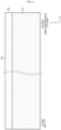
- FIG. 4 illustrates a structure of an electrode
- FIG. 5 illustrates a winding process of an electrode
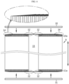
- FIG. 6 illustrates a process in which a current collector plate is welded to a bent surface region of an uncoated portion.
- the positive electrode 10 and the negative electrode 11 have a structure in which an active material 21 is coated on a sheet-shaped current collector 20, and include an uncoated portion 22 at one long side along the winding direction X.
- the long side means a side that is parallel to the X-axis direction and is relatively long.
- the electrode assembly A is manufactured by sequentially stacking the positive electrode 10 and the negative electrode 11 together with two separators 12 as shown in FIG. 5 and then winding them in one direction X.
- the uncoated portions of the positive electrode 10 and the negative electrode 11 are disposed in opposite directions.
- the positive electrode uncoated portion 10a is formed entirely on the upper portion of the electrode assembly A, and the negative electrode uncoated portion 11a is formed entirely on the lower portion of the electrode assembly A.
- the uncoated portion 10a of the positive electrode 10 and the uncoated portion 11a of the negative electrode 11 are bent toward the core. Following that, current collector plates 30, 31 are welded and coupled to the uncoated portions 10a, 11a, respectively.
- the current collector plates 30, 31 are connected to external electrode terminals, and a current path is formed in a large cross-sectional area along the winding axis direction (refer to an arrow) of the electrode assembly A, there is an advantage in that the resistance of the secondary battery may be lowered. This is because resistance is inversely proportional to the cross-sectional area of the path through which the current flows.
- the uncoated portions 10a, 11a should be bent as flat as possible by applying strong pressure to welding regions of the uncoated portions 10a, 11a.
- the shapes of the uncoated portions 10a, 11a may be irregularly distorted and deformed.
- the deformed portion may be in contact with the electrode having the opposite polarity to cause an internal short circuit or may cause a minute crack in the uncoated portions 10a, 11a.
- the uncoated portion 32 adjacent to the core 33 of the electrode assembly A is bent to block the cavity completely or substantially in the core of the electrode assembly A.
- a problem arises in the electrolyte injection process. That is, the cavity in the core 33 of the electrode assembly A is used as a passage through which the electrolyte is injected. However, when the corresponding passage is blocked, it is difficult to inject the electrolyte.
- the electrolyte injector is inserted into the cavity in the core 33, it may interfere with the uncoated portion 32 near the core 33, whereby the uncoated portion 32 is torn.
- bent portions of the uncoated portions 10a, 11a to which the current collector plates 30, 31 are welded should be overlapped in multiple layers, and there should be no empty space (gap). Only then, sufficient welding strength may be obtained, and even when the latest technology such as laser welding is used, it is possible to prevent the problem that the laser may penetrate the electrode assembly A to melt the separator 12 or the active material 21.
- the positive electrode uncoated portion 10a is formed entirely on top of the electrode assembly A, and thus, when the outer circumferential surface of the upper end of the battery can is pressed inward to form a beading portion, the upper edge portion 34 of the electrode assembly A is pressed by the battery can. Such pressure may cause partial deformation of the electrode assembly A, and at this time, the separator 12 may be torn, resulting in an internal short circuit. If a short circuit occurs inside the secondary battery, heat generation or explosion may occur.
- the uncoated portions 10a, 11a should not be entirely formed at the top and bottom of the electrode assembly A as they are now, and need to be omitted in some sections.
- the resistance according to the lengthwise direction current path inside the aforementioned electrode assembly is increased, and thus it should also be considered to design a low-resistance cell minimizing the current path in a tap-less cylindrical secondary battery.
- the form factor is increased to apply the cylindrical secondary battery to an electric vehicle, a large amount of heat may be generated during the fast charge process to cause a problem of ignition of the cylindrical secondary battery, thereby making it more important to design a low-resistance cell minimizing the current path.
- the present disclosure has been devised under the background of the prior art as described above and is designed to solve the problems of the related art, and therefore the present disclosure is directed to providing an electrode assembly that minimizes a current path, particularly a lengthwise direction current path to implement low resistance in a cylindrical secondary battery, and thus, in which a cylindrical secondary battery may exhibit excellent quality in terms of a degree of heat generation due to a high current density while having a large capacity and/or high output.
- the present disclosure is also directed to providing a secondary battery including the electrode assembly having an improved structure to minimize a current path, a battery pack including the same, and a vehicle including the battery pack.
- the electrode assembly of the present disclosure for solving the above-described problem is an electrode assembly defining a core and an outer circumferential surface by winding a positive electrode, a negative electrode, and a separator interposed therebetween around a winding axis, wherein the positive electrode or the negative electrode includes a sheet-shaped current collector that has a long side and a short side and has an uncoated portion at an end of the long side, wherein the uncoated portion includes an electrode tab defined section used as an electrode tab by itself and at least one electrode tab undefined section not used as an electrode tab, wherein a maximum current path for at least one electrode tab undefined section includes a widthwise direction current path along the short side of the current collector and a lengthwise direction current path along the long side of the current collector, and the current path ratio L2/L1 is 11 or less when lengths of the widthwise direction current path and the lengthwise direction current path are L1 and L2, respectively.
- the current path ratio L2/L1 may be 10.15 or less.
- the current path ratio L2/L1 may be 8.5 or less, or 2 to 5.
- a height of the uncoated portion of the electrode tab undefined section may be smaller than that of the electrode tab defined section.
- a maximum value of a length of the at least one electrode tab undefined section may be 4% to 23% of the lengths of the positive electrode and the negative electrode.
- a maximum value of a length of the at least one electrode tab undefined section may be 2.5 to 11 times of widths of the positive electrode and the negative electrode.
- the uncoated portion may include a first portion adjacent to the core, a second portion adjacent to the outer circumferential surface, and a third portion between the first portion and the second portion, and the first portion may have a height smaller than that of the third portion in a winding axis direction.
- the third portion may be defined as an electrode tab in a bent state along a radial direction of the electrode assembly.
- the second portion may have a height equal to or smaller than that of the third portion in the winding axis direction.
- the second portion and the third portion may be defined as electrode tabs in a bent state along the radial direction of the electrode assembly.
- the short side length of the current collector may be 60mm to 85mm, and the long side length of the current collector may be 3 m to 5 m.
- the maximum value of the length along the long side of the current collector in the first portion may be 4% to 23% of a length of the long side of the current collector.
- the length along the long side of the current collector in the first portion may be 660 mm or less.
- the first portion may correspond to the electrode tab undefined section.
- the first portion may not be bent along the radial direction of the electrode assembly.
- the second portion may not be bent along the radial direction of the electrode assembly.
- the length of the third portion may be longer than that of the first portion and that of the second portion in the winding direction of the electrode assembly.
- the first portion may start from a short side of the core of the current collector, the height of the first portion may be constant along the winding direction, and the first portion may not be bent along the radial direction of the electrode assembly.
- At least a partial region of the third portion may be divided into a plurality of independently bendable segment pieces.
- the segment pieces are bent and overlapped in the winding axis direction.
- the short side length of the current collector is 60mm to 85mm
- the long side length of the current collector is 3 m to 5 m
- the thickness of the current collector is 5 ⁇ m to 25 ⁇ m
- the width of the segment pieces is 3 mm-10 mm
- the height of the segment pieces is 10 mm or less.
- the length along the long side of the current collector in the first portion is 660 mm or less.
- the electrode assembly includes sequentially along the radial direction based on a cross section along the winding axis direction, a segment pieces omission section in which segment pieces are not present, and a height uniform section in which the height of the segment pieces is uniform, wherein the plurality of segment pieces are disposed in the height uniform section and are bent along the radial direction of the electrode assembly to form a bent surface region.
- the electrode assembly further includes a height variable section in which the height of the segment pieces is variable between the segment pieces omission section and the height uniform section, wherein the plurality of segment pieces are disposed in the height variable section and the height uniform section and may be bent along the radial direction of the electrode assembly to form a bent surface region.
- the segment pieces omission section may correspond to the at least one electrode tab undefined section.
- the second portion is not divided into segment pieces, and the heights of the first portion and the second portion may be the same.
- the third portion may include at least one segment pieces omission section in which there are no segment pieces along the winding direction of the electrode assembly.
- the height of the uncoated portion in the segment pieces omission section may be the same as that of the first portion.
- the segment pieces may be positioned in at least two sectoral or polygonal regions arranged in a circumferential direction based on the core.
- segment pieces omission section may correspond to the at least one electrode tab undefined section.
- a cavity may be provided in the core, the third portion may be defined as an electrode tab in a bent state along the radial direction of the electrode assembly, the third portion may be divided into a plurality of independently bendable segment pieces, and the bent segment pieces may not block the cavity.
- the maximum value of the length along the long side of the current collector in the first portion may be 4% to 23% of a length of the long side of the current collector.
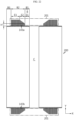
- a secondary battery of the present disclosure for solving the above other problem includes an electrode assembly according to the present disclosure; a cylindrical battery housing accommodating the electrode assembly through an opening formed on one side and connected to the uncoated portion of the negative electrode; a sealing body that seals the opening of the battery housing to be insulated from the battery housing; and a positive electrode terminal that is riveted through a through hole formed at the bottom of the battery housing located on the opposite side of the opening of the battery housing, and is connected to the uncoated portion of the positive electrode.
- the uncoated portion of the positive electrode is exposed to the outside of the separator, and the uncoated portion of the negative electrode is exposed to the outside of the separator in a direction opposite to the uncoated portion of the positive electrode, and the secondary battery further includes a positive electrode current collector plate electrically connected to the uncoated portion of the positive electrode and a negative electrode current collector plate electrically connected to the uncoated portion of the negative electrode.
- the secondary battery may have a DC resistance of 4 mQ or less, and an AC resistance of 3 mQ or less.
- the secondary battery may have an AC resistance of 2 mQ or less.
- the secondary battery may have a ratio of diameter to height greater than 0.4.
- the sealing body may include a cap plate having no polarity and a sealing gasket interposed between an edge of the cap plate and an opening of the battery housing.
- the positive electrode terminal may include a body portion inserted into the through hole; an outer flange portion extending along the outer surface from the circumference of one side of the body portion exposed through the outer surface of the bottom of the battery housing; an inner flange portion extending toward the inner surface from the circumference of the other side of the body portion exposed through the inner surface of the bottom of the battery housing; and a flat portion provided inside the inner flange portion.
- the secondary battery may further include a positive electrode current collector plate electrically connected to the uncoated portion of the positive electrode and a negative electrode current collector plate electrically connected to the uncoated portion of the negative electrode, wherein the positive electrode terminal may be coupled to the positive electrode current collector plate by laser welding in the flat portion.
- the electrode tab undefined section may not be connected to the negative electrode current collector plate and the positive electrode current collector plate, and thus it may not be a portion forming a current path.
- Another object of the present disclosure may be achieved by a battery pack including a plurality of the above-described secondary batteries.
- the plurality of secondary batteries are arranged in a predetermined number of rows, and the positive electrode terminal of each secondary battery and an outer surface of the bottom of the battery housing are disposed to face upward.
- Another object of the present disclosure may also be achieved by a vehicle including at least one of the battery packs.
- an upper limit of the current path ratio L2/L1 in the maximum current path is presented.
- the range of the current path ratio L2/L1 corresponds to a range in which the electrode assembly may minimize internal resistance while having a large capacity. Therefore, a secondary battery including such an electrode assembly may exhibit excellent quality in terms of the degree of heat generation due to the high current density, while having a large capacity and/or high output.
- the internal resistance of the secondary battery may be reduced and the energy density may be increased.
- the uncoated portion of the electrode assembly by improving the structure of the uncoated portion of the electrode assembly, it is possible to prevent the uncoated portion from being torn when the uncoated portion is bent, and by sufficiently increasing the number of overlapping layers in the uncoated portion, it is possible to improve the welding strength of the current collector plate.
- an electrode assembly having improved energy density and reduced resistance by applying a structure in which a current collector plate is welded in a wide area to a bent surface region formed by bending the segment pieces.
- a cylindrical secondary battery having an improved design may be provided to perform electrical wiring at the top.
- the structure of the uncoated portion adjacent to the core of the electrode assembly is improved to prevent a cavity in the core of the electrode assembly from being blocked when the uncoated portion is bent, so that an electrolyte injection process, and a welding process of the battery housing (or positive electrode terminal) and the current collector plate may be easily performed.
- a cylindrical secondary battery having a low internal resistance, preventing an internal short circuit, and having an improved welding strength between a current collector plate and an uncoated portion, a battery pack and a vehicle including the same.
- the present disclosure may provide a cylindrical secondary battery having a DC resistance of 4 mQ or less, an AC resistance of 3 mQ or less, and a ratio of diameter to height of 0.4 or more, a battery pack and a vehicle including the same.
- a statement that two objects of comparison are 'identical' means 'substantially identical'. Therefore, 'substantially identical' may include deviations considered to be low in the art, for example, deviations within 5%. Also, uniformity of a certain parameter in a predetermined region may mean that it is uniform in terms of an average.
- each component may be singular or plural.
- Placing any component on the "upper (or lower)" of a component or “top (or below)” of a component may mean that any component is disposed in contact with the top (or bottom) surface of the component, and also may mean that other components may be interposed between the component and any component disposed on (or under) the component.
- connection may include an electrical connection or a physical connection.
- a direction along the lengthwise direction of the winding axis of the electrode assembly wound in a jelly-roll shape is referred to as a winding axis direction (Y-axis direction).
- a direction surrounding the winding axis is referred to as a circumferential direction or a perimeter direction (X-axis direction).
- a direction closer to or away from the winding axis is referred to as a radial direction.
- One of the features of the present disclosure is to set a maximum current path in a positive electrode and/or a negative electrode constituting a jelly-roll type electrode assembly in order to minimize resistance in a cylindrical secondary battery.
- the present disclosure presents an upper limit of the current path ratio L2/L1 with respect to the length L1 of the widthwise direction current path along the short side of the current collector and the length L2 of the lengthwise direction current path along the long side of the current collector in the maximum current path.
- the range of this current path ratio corresponds to a range in which the electrode assembly may minimize internal resistance while having a large capacity, and when the upper limit of the current path ratio L2/L1 is exceeded, it is not possible to satisfy the minimum resistance requirement of the secondary battery (e.g., DC resistance of 4 mQ or less, and AC resistance of 3 mQ or less).
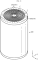
- FIG. 7 is a view for describing an electrode assembly according to an embodiment of the present disclosure.
- the electrode assembly 100 includes a positive electrode 40, a negative electrode 50, and a separator 60 interposed therebetween.
- the electrode assembly 100 may be a jelly-roll type electrode assembly having a structure in which the positive electrode 40, the negative electrode 50, and the separator 60 are wound in one direction.
- the electrode assembly 100 may be manufactured by winding a stack, which is formed by sequentially stacking the positive electrode 40, the separator 60, the negative electrode 50, and the separator 60 at least once, in one direction (X-axis direction in the drawing) with respect to the winding axis B.
- An innermost side of the electrode assembly 100 is defined as a core, and an outermost side is defined as an outer circumferential surface.
- the X-axis direction is the winding direction.
- the core may be provided with a cavity.
- the diameter of the cavity may be, for example, 2 mm to 8 mm.
- the cavity may be a position from which a winding core serving as the winding axis is subtracted.
- the cavity is a moving passage of the electrolyte when the electrolyte is injected, and thus it should have a predetermined size or more in order to smoothly achieve the electrolyte impregnation. Therefore, it is preferable that the cavity diameter is 2 mm or more as far as possible at the level of the allowable winding process, and when the cavity diameter exceeds 8 mm, the use of the internal space is inefficient, which is not preferable in terms of energy density.
- the positive electrode 40 has a structure in which a positive electrode active material layer 40b is coated on one or both surfaces of a sheet-shaped positive electrode current collector having a long side and a short side, and includes a positive electrode uncoated portion 40a in which an active material is not coated on one end of the long side along the winding direction.
- the long side is in a direction parallel to the X-axis direction and means a side having a relatively long length.
- the X-axis direction may be referred to as a lengthwise direction.
- the short side is in a direction parallel to the Y-axis direction in the drawing and means a side having a shorter length than the long side.
- the Y-axis direction may be referred to as a widthwise direction.
- the positive electrode uncoated portion 40a is defined as an electrode tab by itself, and is distinguished from the prior art in which a strip-shaped electrode tab is separately attached.
- an electrode tab means that it becomes a portion forming a current path by being coupled to a current collector when manufactured as a secondary battery.
- only a part of the positive electrode uncoated portion 40a is defined as an electrode tab. This means that a part of the positive electrode uncoated portion 40a is not used as an electrode tab.
- the part not used as the electrode tab is not connected to the current collector plate due to a lower height in the winding axis direction (Y-axis direction) compared to other parts of the positive electrode uncoated portion 40a or omission in some sections, and thus may refer to a part that does not form a current path. As such, it is further distinguished from the prior art in that only a part of the positive electrode uncoated portion 40a is defined as an electrode tab. As described above, the positive electrode uncoated portion 40a may include an electrode tab defined section used as an electrode tab by itself and at least one electrode tab undefined section not used as an electrode tab.
- the negative electrode 50 also has a structure in which a negative electrode active material layer 50b is coated on one or both surfaces of a sheet-shaped negative electrode current collector having a long side and a short side, and includes a negative electrode uncoated portion 50a in which an active material is not coated on one end of the long side along the winding direction.
- the negative electrode uncoated portion 50a is also defined as an electrode tab by itself.
- only a part of the negative electrode uncoated portion 50a is defined as an electrode tab.
- the negative electrode uncoated portion 50a may include an electrode tab defined section used as an electrode tab by itself and at least one electrode tab undefined section not used as an electrode tab.
- the positive electrode uncoated portion 40a and the negative electrode uncoated portion 50a are disposed in opposite directions, and the electrode assembly 100 after winding is completed has a substantially cylindrical shape.
- the positive electrode uncoated portion 40a is positioned at the upper end of the electrode assembly 100
- the negative electrode uncoated portion 50a is positioned at the lower end of the electrode assembly 100.
- a part of the positive electrode uncoated portion 40a protruding upward and a part of the negative electrode uncoated portion 50a protruding downward are used as electrode tabs, and each current collector plate is welded and connected thereto, so that a tab-less cylindrical secondary battery with improved current collecting efficiency may be manufactured.
- the electrode assembly 100 is further distinguished from the prior art in that the ratio (L2/L1, "current path ratio") of a length L2 of the lengthwise direction current path along the long side of the current collector constituting the second path of the electrode to a length L1 of the widthwise direction current path along the short side of the current collector constituting the second path (maximum current path) of the electrode is 11 or less in the positive electrode 40 or the negative electrode 50, which is an electrode included in the electrode assembly 100.
- the short side and the long side of the electrode current collector correspond to the width and length of the electrode, respectively. Therefore, in the maximum current path of the positive electrode 40 or the negative electrode 50, the ratio L2/L1 of the length L2 of the lengthwise direction current path to the length L1 of the widthwise direction current path is 11 or less.
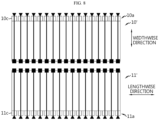
- FIG. 8 schematically illustrates the flow of current or electrons in the positive electrode or the negative electrode constituting the virtual electrode assembly (the connection positions of the first path and the second path are marked with a triangle, and an end point of the electrode is marked with a square).
- the positive electrode 10' and the negative electrode 11' shown in FIG. 8 have a structure in which a plurality of positive electrode tabs 10c and a plurality of negative electrode tabs 11c are formed by notching the uncoated portion 10a of the positive electrode 10 and the uncoated portion 11a of the negative electrode 11 in the widthwise direction in the prior art described with reference to FIGS. 4 to 6 .
- the electrode assembly including the positive electrode 10' and the negative electrode 11' shown in FIG. 8 is manufactured as a cylindrical secondary battery, and the module bus bar welding position is the same as that of the secondary battery described with reference to FIG. 2
- the first path which is a path leading to the electrode tabs 10c, 11c of each electrode 10', 11', will also be the same as in the secondary battery described with reference to FIG. 2 .
- the second path (maximum current path) of the electrodes 10', 11' is clearly different from that of FIG. 3 as shown in FIG. 8 .
- the length of the current path in the widthwise direction of both the positive electrode 10' and the negative electrode 11' is short at the level of the length in the widthwise direction, and the movement in the lengthwise direction is shorter than the conventional second path shown in FIG. 3 due to the uncoated portions 10a, 11a that exist almost continuously.
- the positive electrode tab 10c of the positive electrode 10' and the negative electrode tab 11c of the negative electrode 11' are placed at positions corresponding to each other in the upper and lower portions of the electrode assembly, the movement in the lengthwise direction is little or very short as illustrated. Therefore, the maximum current path of the electrodes 10', 11' becomes substantially the same as the widthwise direction current path of the electrodes.
- the length of the widthwise direction current path of the maximum current path is actually short at the level of the distance in the widthwise direction of the electrode, and the lengthwise direction current path of the electrode is very short. Therefore, the current path ratio will be close to zero.
- FIG. 8 shows a structure in which the electrode tabs 10c, 11c are formed approximately continuously along the lengthwise direction of the electrodes 10', 11', but preferably, a region from which the electrode tabs are removed may exist.
- the electrode assembly according to an embodiment of the present disclosure may have a shape in which the uncoated portion is bent toward the core.
- the uncoated portion close to the core may not be bent, a height in the winding direction may be lowered, or a significant portion may be removed and left as the electrode tab undefined section as described above.
- the electrode tab undefined section may be formed close to the core side of the electrode assembly after the electrode is wound.
- the electrode tab undefined section may be provided at a plurality of locations between one end and the other end in the lengthwise direction based on the time before the electrode is wound.
- the length in the winding direction of the electrode tab defined section may be variously set according to the position and length of the electrode tab undefined section.
- the maximum current path of the electrode may be defined in the electrode tab undefined section having the longest length in the winding direction. Since electrons should move toward the electrode tab defined section in the electrode tab undefined section, the maximum current path is defined in the electrode tab undefined section having the longest length. Therefore, as the length in the winding direction of the electrode tab undefined section increases, the current path ratio inevitably becomes longer than in the case shown in FIG. 8 . Also, the current path ratio may vary depending on the position of the electrode tab defined section.
- the maximum current path varies depending on how the position of the electrode tab defined section is set, and as the maximum current path becomes smaller, the resistance of the electrode decreases.
- the upper limit of the current path ratio L2/L1 in the maximum current path for the electrode tap undefined section is limited to satisfy the low resistance condition. That is, the range of the current path ratio L2/L1 may be limited so that the resistance of the secondary battery does not increase beyond a predetermined range.
- the upper limit of the current path ratio L2/L1 in the maximum current path for the electrode tap undefined section is limited to a predetermined range while including the electrode tap undefined section in at least a partial section of the uncoated portion.
- the present disclosure provides a guide on how long the electrode tab undefined section may be set while minimizing the increase in resistance of the secondary battery.
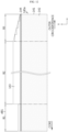
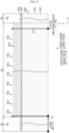
- FIG. 9 is a plan view illustrating an electrode structure of a first embodiment that may be included in the electrode assembly of FIG. 7 .
- the electrode 140 which may be the positive electrode 40 or the negative electrode 50 shown in FIG. 7 , includes an electrode current collector 141 made of a metal foil and an active material layer 142.
- the metal foil may be a conductive metal, such as aluminum or copper, and is appropriately selected according to the polarity of the electrode 140.
- the thickness of the positive electrode current collector (foil) may be 10 ⁇ m to 20 ⁇ m, and the thickness of the negative electrode current collector (foil) may be 5 ⁇ m to 15 ⁇ m.
- the short side length of the current collector 141 may be 60 mm to 85 mm, and the long side length of the current collector 141 may be 3 m to 5 m.
- the ratio of the short side to the long side of the current collector 141 may be 1.2% to 2.8%, which is significantly smaller than the level of 6% to 11% in a cylindrical secondary battery having a form factor of 1865 or 2170. That is, the current collector 141 is very long in the lengthwise direction and has a very large number of winding turns when wound. The winding turn may be counted based on the core-side end of the electrode assembly 100.
- An active material layer 142 is formed on at least one surface of the current collector 141.
- the active material layer 142 is formed along the winding direction (X-axis direction).
- the electrode 140 includes an uncoated portion 143 at the long side end in the winding direction.
- the uncoated portion 143 is a partial region of the current collector 141 that is not coated with an active material. A part of the uncoated portion 143 in the winding direction is set as an electrode tab undefined section, and the rest is set as an electrode tab defined section.
- the electrode 140 is manufactured by forming the active material layer 142 on the current collector 141 and then pressing it.
- an insulating coating layer 144 may be formed at a boundary between the active material layer 142 and the uncoated portion 143. At least a portion of the insulating coating layer 144 is formed to overlap the boundary between the active material layer 142 and the uncoated portion 143.
- the insulating coating layer 144 prevents a short circuit between two electrodes 140 having different polarities facing each other with a separator (refer to 60 in FIG. 7 ) interposed therebetween, that is, the positive electrode 40 and the negative electrode 50.
- the insulating coating layer 144 may have a width of 0.3 mm to 5 mm to cover the boundary between the active material layer 142 and the uncoated portion 143.
- the width of the insulating coating layer 144 may vary along the winding direction of the electrode 140.
- the insulating coating layer 144 may include a polymer resin and an inorganic filler such as Al 2 O 3 . Since the portion of the current collector 141 covered by the insulating coating layer 144 is not a region coated with the active material layer, it may be regarded as an uncoated portion.
- the uncoated portion 143 includes a first portion B1 adjacent to the core of the electrode assembly 100, a second portion B3 adjacent to the outer circumferential surface of the electrode assembly 100, and a third portion B2 between the first portion B1 and the second portion B3.
- the boundary of B1/B2 may be appropriately defined as a point at which the height (or change pattern) of the uncoated portion substantially changes from the core side of the electrode assembly to the outer circumferential side, or a point at a predetermined percentage based on the radius of the electrode assembly (e.g., 5%, 10%, 15% of the radius, etc.).
- the boundary of B2B3 may also be appropriately defined as a point at which the height (or change pattern) of the uncoated portion substantially changes from the outer circumferential side of the electrode assembly to the core side, or a point at a predetermined percentage based on the radius of the electrode assembly (e.g., 85%, 90%, 95% of the radius, etc.).
- the height of the uncoated portion 143 is not constant and there is a relative difference in the winding direction. That is, the first portion B1 has a smaller height in the winding axis direction than the third portion B2. After the uncoated portion 143 is formed with a constant height, the uncoated portion of the first portion B1 may be cut larger than the uncoated portion of the third portion B2 to have such a height difference.
- the height of each portion may be an average height or a maximum height, and is the same hereafter.
- the heights of the first portion B1 and the second portion B3 in the winding axis direction may be 0 or more, and the heights of the first portion B1 and the second portion B3 may be the same or different from each other.
- the case in which the heights of the first portion B1 and the second portion B3 are different, and the height of the second portion B3 is equal to the height of the third portion B2 is taken as an example.
- the first portion B1 corresponds to the electrode tab undefined section
- the third portion B2 corresponds to the electrode tab defined section.
- the second portion B3 may also be set as the electrode tab defined section.
- the third portion B2 may be defined as an electrode tab in a bent state along the radial direction of the electrode assembly 100.
- the second portion B3 may also be defined as an electrode tab in a bent state along the radial direction. Since the first portion B1 is not bent along the radial direction and does not make electrical contact with a current collector plate to be described later, the current (electrons) flows in a detour through the adjacent third portion B2 during the occurrence of the redox reaction in the first portion B1.
- the second portion B3 may be bent to become a welding region.
- the length d B2 of the third portion B2 may be longer than the length d B1 of the first portion B1.
- the length d B2 of the third portion B2 may be longer than the length d B3 of the second portion B3.
- the first portion B1 corresponding to the electrode tab undefined section is close to the core.
- the third portion B2 is wound. Since the third portion B2 is located farther than the core by the first portion B1, the third portion B2 is not deformed when the third portion B2 is bent.
- the height of the first portion B1 is small and is not bent, so that the cavity in the core of the electrode assembly 100 is not blocked. If the cavity of the core is not blocked, there is no difficulty in the electrolyte injection process, and the electrolyte injection efficiency is improved.
- a welding jig may be inserted through the core to easily perform a welding process between the current collector plate on the negative electrode (or positive electrode) side and the battery housing (or electrode terminal).
- the uncoated portion of the first portion B1 may be cut larger than the uncoated portion of the third portion B2 to have a height difference, and thus the first portion B1 is not used as an electrode tab.
- the resistance increases as the maximum current path increases, compared to the case in which the entire uncoated portion is designed as the electrode tab defined section.
- the first portion B1 is required in order not to block the cavity of the core while the electrode tab defined section is bent. Even if the length d B1 of the first portion B1 is increased, when the length d B2 of the third portion B2 and the length d B3 of the second portion B3 are relatively longer or the welding area ensured by the third portion B2 is sufficient, the resistance (AC resistance and DC resistance) of the entire cell may not be significantly changed, but the resistance in the first portion B1 is increased. Therefore, it is necessary to limit the length d B1 of the first portion B1 in consideration of an increase in resistance in the first portion B1.
- the denominator is constant as the width of the electrode. Therefore, the length d B1 of the first portion B1 is a factor that determines the current path ratio L2/L1 of the maximum current path.
- the current path ratio L2/L1 of the maximum current path is set to 11 or less by adjusting the length d B1 of the first portion B1, thereby preventing the cavity of the core from being blocked and minimizing the increase in resistance.
- the current path ratio L2/L1 of the maximum current path may be 10.15 or less. More preferably, the current path ratio L2/L1 of the maximum current path may be 8.5 or less.
- the current path ratio L2/L1 of the maximum current path may be 2 to 5.
- Each numerical value may be a value optimized to have a critical effect in consideration of the electrical, physical, and chemical property conditions of the current collector 141 and the active material layer 142, the resistance conditions of the secondary battery, the length d B1 of the first portion B1 required not to block the cavity of the core, the length d B3 of the second portion B3 required to secure an effective welding area while having the appropriate number of overlapping layers, and the length d B2 of the third portion B2.
- the number and length of the electrode tab undefined sections are adjusted while limiting the current path ratio L2/L1 of the maximum current path to a predetermined range, and the rest are designed as the electrode tab defined sections.
- FIG. 9 shows a maximum current path according to an embodiment (the connection positions of the first path and the second path are marked with a triangle, and an end point of the electrode is marked with a square).
- the maximum current path is included in the first portion B1, which is an electrode tab undefined section.
- the maximum current path corresponds to a path having the maximum length of a path through which current (electrons) flows when an electrochemical redox reaction occurs in the first portion B1.
- the length L1 of the widthwise direction current path of the maximum current path is as short as the short side length of the current collector 141 or the electrode 140.
- the length L1 of the widthwise direction current path is the minimum length from one end of long side of the uncoated portion 143 to the other end of long side of the current collector 141. Since the heights of the second portion B3 and the third portion B2 are the same, the length of the widthwise direction current path of the electrode 140 is the same as the short side length (width) of the electrode 140, and since the uncoated portion of the second portion B3 is not cut, it is the same as the short side length of the current collector 141.
- the current path ratio of the maximum current path is L2/L1 and L1 corresponds to the width of the electrode 140, so the current path ratio may be adjusted by using the length d B1 of the first portion B1.
- the upper limit of the current path ratio L2/L1 may be a value such that the DC resistance of the secondary battery including the electrode assembly 100 is 4 mQ or less and the AC resistance is 3 mQ or less. More preferably, the upper limit of the current path ratio L2/L1 may be a value such that the AC resistance of the secondary battery including the electrode assembly 100 is 2 mQ or less.
- the resistance of the secondary battery may vary depending on the electrical, physical, and chemical property conditions of the current collector 141 and the active material layer 142, for example, when the short side length of the current collector 141 is 60 mm to 85 mm, the long side length of the current collector 141 is 3m to 5m, and the thickness of the current collector 141 is 5 ⁇ m to 20 ⁇ m, the length d B1 of the first portion B1 may be 660mm or less. In this case, the maximum value of the length d B1 of the first portion B1 is 660 mm, and in consideration of the long side length of the current collector 141, the maximum value of the length d B1 of the first portion B1 may be 13.2% to 22% of the long side length of the current collector 141.
- the maximum value of the length d B1 of the first portion B1 may be 4% to 23%. That is, the maximum value of the length of a portion that is not defined as an electrode tab in the electrode 140, that is, the electrode tab undefined section is 660 mm, and in consideration of the point that the long side length of the current collector 141 becomes the long side length of the electrode 140 as it is, it may be seen as 4% to 23% of the length of the electrode 140.
- the short side length of the current collector 141 becomes the short side length of the electrode 140 as it is, it may be seen that 660 mm, which is the maximum value of the length of a portion not defined as an electrode tab in the electrode 140, is 9.4 times to 11 times the width of the electrode 140.
- the maximum value of the length d B1 of the first portion B1 may be 2.5 times to 11 times.
- the current path ratio L2/L1 may be 10.15.
- the current path ratio L2/L1 may be further reduced by making the length d B1 of the first portion B1 smaller than 660 mm.
- the upper limit of the current path ratio L2/L1 may be such that a minimum resistance requirement of the secondary battery is satisfied. That is, the secondary battery resistance may be determined to be smaller than the maximum value of the secondary battery resistance.
- the maximum value of DC resistance of 4mQ and the maximum value of AC resistance of 3mQ, which are applied in this embodiment, may vary depending on the specification of the secondary battery.
- the inventors of the present disclosure confirmed through simulation that the resistance of the secondary battery increases as the length of the electrode tab undefined section increases as in the first portion B1. However, it was confirmed that the resistance no longer increases and converges when the length of the electrode tab undefined section is increased to a certain level or higher. By examining the correlation between the length of the electrode tab undefined section and the resistance of the secondary battery, it was possible to determine the length of the electrode tab undefined section that satisfies the minimum resistance requirement of the secondary battery.
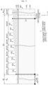
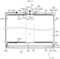
- FIG. 10 is a schematic diagram of an electrode including an electrode tab undefined section used for simulation
- FIG. 11 is a graph of resistance according to the number of welding points confirmed through simulation.
- FIG. 10 illustrates a case in which the electrode tabs 143a1 are present at equal intervals, the connection positions of the first path and the second path are marked with a triangle, and an end point of the electrode is marked with a square.
- the number of electrode tabs 143a1 is 6, the number of electrode tab undefined sections 143a2 is 7, and if the number of electrode tabs 143a1 is 7, the number of electrode tab undefined sections 143a2 is 8.
- the number of electrode tabs 143a1 is Q
- the equal interval condition in which the number of electrode tab undefined sections 143a2 is Q+1 is assumed. Since each electrode tab 143a1 is welded to the current collector plate, the number of welding points is the same as the number of electrode tabs 143a1.
- the short side length of the current collector 141' included in the electrode 140' is 60 mm to 85 mm
- the long side length of the current collector 141' is 3 m to 5 m
- the thickness of the current collector 141' is 5 ⁇ m to 20 ⁇ m.
- the AC resistance of the secondary battery including an electrode assembly in which the electrode 140' includes a positive electrode and a negative electrode was simulated while increasing the number of electrode tabs 143a1 from 1 to 50. Referring to FIG. 11 corresponding to the result, it can be seen that the resistance converges as the number of electrode tabs 143a1 increases, and the number of electrode tabs 143a1 in which the AC resistance of the secondary battery is 2 m ⁇ or less under the simulation condition is six.
- the number of electrode tabs 143a1 may be converted into the length of the electrode tab undefined section 143a2.
- the width of the electrode tab 143a1 is 10 mm
- the length of one electrode tab undefined section 143a2 is 660mm.
- the length of one electrode tab undefined section 143a2 is 564 mm.
- the AC resistance of the secondary battery was simulated as 1.7 m ⁇ .
- the length of the electrode tab undefined section 143a2 is preferably set to 660 mm or less.
- the ratio of the length of the electrode tab undefined section 143a2 corresponding to the lengthwise direction current path to the short side length of the current collector 141' corresponding to the widthwise direction current path is 11 or less. Therefore, when the electrode tab undefined section is included, it was concluded that the low resistance condition in which the AC resistance of the secondary battery is 2 mQ or less can be satisfied as long as the current path ratio L2/L1 is set to 11 or less.
- the length d B1 of the first portion B1 is set to 660 mm or less, as proposed in this embodiment.
- the cell resistance may satisfy the minimum resistance requirement of the secondary battery.
- the length d B1 of the first portion B1 may be designed under the condition satisfying the current path ratio (L2 /L1) by applying a condition that the cavity provided in the core of the electrode assembly 100 is not blocked when the uncoated portion of the third portion B2 is bent toward the core,
- the length d B1 of the first portion B1 may be determined according to a necessary condition in 660 mm or less, and when the length d B1 of the first portion B1 is 660 mm and the short side length of the current collector 141 is 65 mm, the current path ratio L2/L1 may be 10.15, whereby the current path ratio L2/L1 may satisfy the range of 10.15 or less according to the length d B1 of the first portion B1.
- the current path ratio increases compared to the case in which all uncoated portions such as the third portion B2 are included without the first portion B1, but the length d B1 of the first portion B1 may be increased until the current path ratio L2/L1 becomes 10.15 or less as a guide satisfying the minimum resistance, whereby it is possible not to block the cavity provided in the core of the electrode assembly 100 when the uncoated portion of the third portion B2 is bent toward the core.
- FIG. 12 is a plan view illustrating an electrode structure of a second embodiment that may be included in an electrode assembly according to another embodiment of the present disclosure.
- the electrode 145a shown in FIG. 12 is different in that the height of the second portion B3 is gradually decreased toward the outer periphery, and the remaining configurations are substantially the same.
- the second portion B3 may be deformed into a step shape (refer to dotted line) in which the height is gradually decreased. In these, the second portion B3 has a smaller height than the third portion B2.
- FIG. 13 is a plan view illustrating an electrode structure of a third embodiment that may be included in an electrode assembly according to another embodiment of the present disclosure.
- the heights of the first portion B1 and the second portion B3 are 0 or more, but are relatively smaller than that of the third portion B2.
- the heights of the first portion B1 and the second portion B3 are the same.
- the second portion B3 corresponds to the electrode tab undefined section, so that the uncoated portion of the second portion B3 is not defined as an electrode tab, and the third portion B2 is defined as an electrode tab.
- the length of the second portion B3 is shorter than the length d B1 of the first portion B1.
- the second portion B3 may be an uncoated portion of the electrode region including the outermost winding turn.
- the third portion B2 may be defined as an electrode tab in a bent state along the radial direction of the electrode assembly 100.
- the first portion B1 and the second portion B3 are not bent along the radial direction. According to this embodiment, when the electrode assembly is inserted into the battery housing and the outer circumferential surface of the battery housing is press-fitted to form a beading portion, it is possible to prevent the occurrence of an internal short circuit while the beading portion and the second portion B3 are in contact with each other in the process where the beading portion is pressed near the second portion B3.
- FIG. 14 is a plan view illustrating an electrode structure of a fourth embodiment that may be included in an electrode assembly according to another embodiment of the present disclosure.
- the heights of the first portion B1 and the second portion B3 are 0 or more, but are relatively smaller than that of the third portion B2.
- the heights of the first portion B1 and the second portion B3 may be the same or different from each other.
- the height of the third portion B2 may have a step shape that gradually increases from the core side to the outer circumferential side.
- Patterns 1 to 7 are obtained by dividing the third portion B2 based on the position where the height of the uncoated portion 143 changes.
- the number of patterns and the height (length in the Y-axis direction) and width (length in the X-axis direction) of each pattern may be adjusted to maximize the stress distribution during the bending process of the uncoated portion 143.
- the stress distribution is to prevent the uncoated portion 143 from being torn when the uncoated portion 143 is bent toward the core of the electrode assembly.
- the length d B1 of the first portion B1 is designed by applying a condition that does not block the cavity provided in the core when the patterns of the third portion B2 are bent toward the core, but in one example, the length d B1 of the first portion B1 may increase in proportion to the bending length of the pattern 1.
- the bending length corresponds to the height of the pattern based on the bending point of the pattern.
- the length d B1 of the first portion B1 may be set such that the radial width of the winding turns formed by the first portion B1 is equal to or greater than the bending length of the pattern 1.
- the length d B1 of the first portion B1 may be set such that a value obtained by subtracting the radial width of the winding turns formed by the first portion B1 from the bending length of the pattern 1 is less than 0 or 10% of the core radius or less.
- the length d B1 of the first portion B1 may be set to 180 mm to 350 mm depending on the diameter of the core and the bending length of the pattern 1.
- the current path ratio L2/L1 may be 2.57 to 5.83. If the length d B1 of the first portion B1 is further adjusted, the current path ratio L2/L1 may be 2 to 5.
- the width of each pattern may be designed to constitute one or at least two winding turns of the electrode assembly.
- the height of the third portion B2 may have a step shape that increases and then decreases from the core side to the outer circumferential side.
- the second portion B3 may be deformed to have the same structure as that of the second embodiment.
- the pattern structure applied to the third portion B2 may extend to the second portion B3 (refer to dotted line).
- FIG. 15 is a plan view illustrating an electrode structure of a fifth embodiment that may be included in an electrode assembly according to another embodiment of the present disclosure.
- the third portion B2 may include a plurality of segment pieces 161.
- at least a partial region of the third portion B2 may be divided into a plurality of independently bendable segment pieces 161.
- the height of the plurality of segment pieces 161 may be increased step by step from the core side to the outer circumferential side.
- the plurality of segment pieces 161 have a geometrical figure shape in which the width decreases from the bottom to the top.
- the geometrical figure is trapezoid.
- the shape of the geometrical figure may be modified in various ways.
- the segment pieces 161 may be notched with a laser.
- the segment pieces 161 may be formed by a known metal foil cutting process such as ultrasonic cutting or punching.
- the segment pieces 161 are bent and overlapped in the winding axis direction.
- segment pieces 161 are independently bendable, deformation of the uncoated portion 143 may be further suppressed when the segment pieces 161 are bent, which is preferable.
- the first portion B1 starts from the core short side of the current collector 141, and the height of the first portion B1 is constant along the winding direction and is not bent along the radial direction. Only the segment pieces 161 of the third portion B2 are defined as an electrode tab. Therefore, in the electrode 160, in order that the current path ratio L2/L1, which is a ratio of the length L2 of the lengthwise direction current path along the long side of the current collector 141 to the length L1 of the widthwise direction current path along the short side of the current collector 141, is set to 11 or less, the length from the core end of the electrode 160 to the lower end of the segment pieces 161 first located in the lengthwise direction, here, which is a length equal to the length d B1 of the first portion B1 may be adjusted.
- L2/L1 which is a ratio of the length L2 of the lengthwise direction current path along the long side of the current collector 141 to the length L1 of the widthwise direction current path along the short side of the current collector 141
- the thickness of the current collector 141 may be 5 ⁇ m to 25 ⁇ m
- the width (refer to D in FIG. 16 ) of the segment pieces 161 may be 3 mm to 10 mm
- the height (refer to H in FIG. 16 ) of the segment pieces 161 may be 10 mm or less.
- the plurality of segment pieces 161 may form a plurality of segment pieces group from the core side to the outer circumferential side. At least one of a width, a height, and a spacing pitch of segment pieces belonging to the same segment pieces group may be substantially the same. Preferably, the width, height, and spacing pitch of segment pieces belonging to the same segment pieces group may be equal to each other.
- Dimensions (width, height, spacing pitch) of the segment pieces 161 may be adjusted in consideration of resistance, ease of processing (e.g., whether laser notching can be applied without cracks), ease of bending, degree of overlapping between several segment pieces 161, and the like.
- the width and height of segment pieces belonging to the same segment pieces group may be substantially the same.
- FIG. 16 shows definitions of a width D, a height H, and a spacing pitch P of the trapezoidal segment pieces 161.
- the width D, the height H, and the spacing pitch P of the segment pieces 161 are designed to prevent abnormal deformation of the uncoated portion 143 while sufficiently increasing the number of overlapping layers of the uncoated portion 143 in order to prevent the uncoated portion 143 near the bending point from being torn and ensure sufficient welding strength during the bending processing of the uncoated portion 143.
- the bending of the segment pieces 161 is performed on the line G passing through the lower end of the cutting groove 163 or the upper portion thereof.
- the cutting groove 163 enables smooth and easy bending of the segment pieces 161 in the radial direction of the electrode assembly.
- the width D of the segment pieces 161 is defined as a length between two points where two straight lines extending from both sides 163b of the segment pieces 161 and a straight line extending from the bottom 163a of the cutting groove 163 meet.
- the height H of the segment pieces 161 is defined as the shortest distance between the uppermost side of the segment pieces 161 and a straight line extending from the bottom 163a of the cutting groove 163.
- the spacing pitch P of the segment pieces 161 is defined as a length between two points where a straight line extending from the bottom 163a of the cutting groove 163 and two straight lines extending from two sides 163b connected to the bottom 163a meet.
- the straight line may be replaced with a tangent line extending from the side 163b and/or the bottom 163a at the intersection where the side 163b and the bottom 163a meet.
- the width D of the segment pieces 161 is 1 mm or more. If D is less than 1 mm, a region or an empty space (gap) in which the segment pieces 161 does not overlap enough to ensure welding strength when the segment pieces 161 is bent toward the core may occur.
- the width D of the segment pieces 161 may be adaptively adjusted according to the radius of the winding turn where the segment pieces 161 are positioned so that the overlapping of the segment pieces 161 are well made in the radial direction when the segment pieces 161 are bent toward the core.
- the height H of the segment pieces 161 may be 2 mm or more. If the height H of the segment pieces 161 is less than 2 mm, a region or an empty space (gap) in which the segment pieces 161 do not overlap enough to ensure welding strength when the segment pieces 161 are bent toward the core may occur.
- the height H of the segment pieces 161 may be determined by applying a condition that does not block the cavity of the core when the segment pieces 161 are bent toward the core.
- the height H of the segment pieces 161 may be adjusted so that 90% or more of the diameter of the core may be opened to the outside.
- the height H of the segment pieces 161 may increase from the core to the outer periphery side depending on the radius of the winding turn at which the segment pieces 161 are located and the radius of the core.
- the height H of the segment pieces 161 may be increased in stages over N steps from h1 to h N as the radius of the winding turn increases.
- the total winding turn radius of the electrode 160 is 22 mm, and the height of the segment pieces 161 starts from 3 mm.
- the radius of the winding turn including the segment pieces 161 is increased by 1 mm
- the height of the segment pieces 161 is sequentially increased to 3 mm, 4 mm, 5 mm, 6 mm, and the height may be maintained substantially the same as 6mm in the remaining winding turns. That is, among the radii of the entire winding turns, the radial width of the height variable section of the segment pieces 161 is 3 mm, and the remaining radial section corresponds to the height uniform section.
- the starting radii r 1 , r 2 , r 3 , and r 4 of the winding turn including the segment pieces 161 having heights of 3 mm (hi), 4 mm (h 2 ), 5 mm (h 3 ) and 6 mm (h 4 ) may be 6 mm, 7 mm, 8 mm, and 9 mm, respectively, and the height of the segment pieces 161 may be maintained at 6 mm from the radius 9 mm to the last winding turn.
- the segment pieces 161 may not be included in the winding turn having a radius smaller than 6 mm r 1 .
- the segment pieces 161 with a height of 3 mm h 1 closest to the core C is located from the winding turn having a radius of 6 mm, even if the segment pieces 161 is bent toward the core C, it covers only a radial section of 3 mm to 6 mm, and thus does not substantially block the cavity of the core.
- the height H of the segment pieces 161 may be 10 mm or less.
- an end of the separator 60 may further extend outwardly from an end of the electrode 160 to a length corresponding to the insulation gap.
- a section corresponding to the minimum meandering margin of the separator 60 should be allocated to the uncoated portion 143 in consideration of the fact that the end of the separator 60 causes meandering.
- a minimum cutting scrap margin should be allocated to the end of the current collector foil.
- the insulation gap may be 0.2 mm to 6 mm when the electrode 160 is a positive electrode. Also, the insulation gap may be 0.1 mm to 2 mm when the electrode 160 is a negative electrode.
- the minimum meandering margin of the separator 60 may be 0 to 1 mm.
- the cutting scrap margin may be 1.5 mm to 8 mm.
- the cutting scrap margin may not be allocated according to the process of forming the segment pieces 161.
- the cutting groove 163 may be formed so that the upper side of the segment pieces 161 and the upper side of the current collector foil coincide with each other, and in this case, the cutting scrap margin may be zero.
- the maximum height of the segment pieces 161 in the height variable section of the segment pieces 161 may be set to 10 mm. Therefore, the height of the segment pieces 161 in the height variable section of the segment pieces 161 may be increased in stages or gradually along the radial direction of the electrode assembly in the section of 2 mm to 10 mm.
- the spacing pitch P of the segment pieces 161 may be adjusted in the range of 0.05 mm to 1 mm. If the spacing pitch P is less than 0.05 mm, cracks may occur in the uncoated portion 143 near the lower end of the cutting groove 163 due to stress when the electrode 160 is driven in a winding process or the like. On the other hand, if the spacing pitch P exceeds 1 mm, a region or an empty space (gap) in which the segment pieces 161 do not overlap each other enough to ensure welding strength when the segment pieces 161 are bent may occur.
- the spacing pitch P is set to 0.5 mm or more.
- the spacing pitch P is 0.5 mm or more, even if the electrode 160 is driven at a speed of 100 mm/sec or more under a tension of 300 gf or more in a winding process, or the like, it is possible to prevent cracks from occurring in the lower portion of the cutting groove 163.
- the cutting groove 163 is interposed between two segment pieces 161 adjacent to each other in the winding direction.
- the cutting groove 163 corresponds to a space created when the uncoated portion 143 is removed.
- the corner portions of both ends of the lower portion of the cutting groove 163 have a round shape. That is, the cutting groove 163 includes a substantially flat bottom 163a and a round portion 163c.
- the round portion 163c connects the bottom 163a thereof and the side portion 163b of the segment pieces 161.
- the bottom 163a of the cutting groove 163 may be replaced with an arc shape.
- the side portions 163b of the segment piece 161 may be smoothly connected by the arc shape of the bottom 163a.
- the lower inner angle ⁇ of the plurality of segment pieces 161 may increase from the core to the outer circumferential side.
- the lower inner angle ⁇ of the plurality of segment pieces 161 may increase gradually or in stages from the core to the outer circumferential side.
- the lower inner angle ⁇ is an angle between a straight line extending from the bottom 163a of the cutting groove 163 and a straight line extending from the side portion 163b of the segment pieces 161.
- the radius of curvature increases. If the lower inner angle ⁇ of the segment pieces 161 increases together according to the increase of the radius of the electrode assembly, stress generated in the radial and circumferential directions when the segment pieces 161 is bent may be relieved. In addition, if the lower inner angle ⁇ increases, the area overlapping with the inner segment pieces 161 and the number of overlapping layers also increase when the segment pieces 161 are bent, thereby ensuring uniform welding strength in the radial and circumferential directions and forming a flat bent surface region.
- the lower inner angle ⁇ may be determined by the radius of the winding turn where the segment pieces 161 are positioned and the width D of the segment pieces 161.
- the lower inner angle of the segment pieces 161 may gradually or in stages increase in a range of 60 degrees to 85 degrees in the height variable section.
- the length d B1 of the first portion B1 is designed such that the core is opened to the outside by 90% or more based on its diameter when the segment pieces 161 of the third portion B2 are bent toward the core.
- the length d B1 of the first portion B1 may increase in proportion to the bending length of the segment pieces 161 of the group 1.
- the bending length corresponds to the length from the bending point to the upper end of the segment pieces 161.
- the bending point of the segment pieces 161 may be set at a line passing through the lower end of the cutting groove 163 or at a point spaced apart from the line by a predetermined distance upward.
- overlapping of the segment pieces in the radial direction is better performed.
- the segment pieces 161 are bent, the segment pieces on the outside press the segment pieces on the inside based on the center of the core.
- the bending point is spaced apart from the lower end of the cutting groove 163 by a predetermined distance, the inner segment pieces are pressed in the winding axis direction by the outer segment pieces, and thus overlapping of the segment pieces is better performed.
- the separation distance of the bending point may be preferably 1 mm or less. Since the minimum height of the segment pieces is 2 mm, the ratio of the separation distance of the bending point to the minimum height may be 50% or less.
- each segment pieces group may be designed to constitute the same winding turn of the electrode assembly.
- the winding turn may be counted based on the end of the first portion B1 when the electrode 160 is wound.
- the width of each segment pieces group may be designed to constitute at least one winding turn of the electrode assembly.
- Groups 1 to 8 are only examples of the segment pieces group included in the third portion B2.
- the number of groups, the number of segment pieces 161 included in each group, and the width of the group may be preferably adjusted so that the segment pieces 161 are overlapped in multiple layers so as to distribute stress to the maximum during the bending process of the uncoated portion 143 and ensure sufficient welding strength with the current collector.
- a section (groups 1 to 7) in which the height of the segment pieces 161 is increased step by step based on the winding direction of the electrode 160 may be defined as a height variable section of the segment pieces, and the last segment pieces group (group 8) may be defined as a height uniform section in which the height of the segment pieces is maintained uniformly.
- a section in which the segment pieces 161 having a height of hi to h N-1 (N is a height index, and a natural number of 2 or more) are disposed corresponds to the height variable section, and a section in which the segment pieces 161 having a height of h N are disposed corresponds to the height uniform section.
- the width of group 1 may be 35-40% of the width of the first portion B1.
- the width of group 2 may be 130-150% of the width of group 1.
- the width of group 3 may be 120-135% of the width of group 2.
- the width of group 4 may be 85-90% of the width of group 3.
- the width of group 5 may be 120-130% of the width of group 4.
- the width of group 6 may be 100-120% of the width of group 5.
- the width of group 7 may be 90-120% of the width of group 6.
- the width of group 8 may be 115-130% of the width of group 7.
- the length d B3 of the second portion B3 may be 180 mm to 350 mm, similar to the width of the first portion B1.
- the widths of groups 1 to 8 do not show a constant increase or decrease pattern is that the width of the segment pieces gradually increases from group 1 to group 8, but the number of the segment pieces included in the group is limited to an integer number, and the thickness of the electrode has a slight deviation in the winding direction. Therefore, the number of segment pieces may be reduced in a particular segment pieces group.
- the width of the group may exhibit an irregular change pattern as in the above example while going from the core side to the outer circumferential side.
- the welding strength of the current collector plate may be improved by sufficiently increasing the number of overlapping layers of the segment pieces 161. Since the number of stacks of the segment pieces 161 in the region used as the welding target region is sufficiently increased by optimizing the dimensions (width, height, and spacing pitch) of the segment pieces 161, the physical properties of the region where the current collector plate is welded may be improved.
- a representative current path is also shown in FIG. 15 .
- the connection position of the first path and the second path is marked with a triangle, and the end point of the electrode is marked with a square.
- the connection position of the first path and the second path may be any position of the second portion B3 and the third portion B2, but one place in group 1 and one place in group 8 are indicated in the drawings for convenience of illustration.
- the electrode end point may also be any position, but one place to show the length L1 of the widthwise direction current path and one place located on the maximum current path are indicated.
- L2 which determines an upper limit of the current path ratio L2/L1
- L2/L1 is the distance from the third portion B2 defined as an electrode tab to the electrode end point, and corresponds to the length d B1 of the first portion B1.
- the current path ratio L2/L1 may be adjusted.
- This current path ratio L2/L1 satisfies the minimum resistance requirement of the secondary battery even though the resistance is slightly increased, and thus it may be lowered to 11 or less, 10.15 or less, 8.5 or less, or in the range of 2 to 5 when further considering the overlapping degree of the segment pieces 161 and securement of welding strength, and the like.
- the current path ratio L2/L1 may be lower to 8.5 or less, or in the range of 2 to 5.
- the present disclosure is meaningful in that the upper limit of the current path ratio L2/L1 is set from the viewpoint of designing a low-resistance cell that minimizes the current path. When the current path ratio L2/L1 exceeds the upper limit, the minimum resistance requirement of the secondary battery may not be satisfied.
- the third portion B2 may be bent to become a welding region.
- the length d B2 of the third portion B2 may be longer than the length d B1 of the first portion B1.
- the length d B2 of the third portion B2 may be longer than the length d B3 of the second portion B3.
- the bent portion may be overlapped in multiple layers during bending. A sufficient welding region may be ensured by increasing the length d B2 of the third portion B2.
- the electrode 160 may include a segment pieces omission section 164 in which some of the plurality of segment pieces are regularly or irregularly omitted as shown in FIG. 17.
- FIG. 17 is a plan view illustrating a deformed structure of an electrode according to a fifth embodiment of the present disclosure.
- the segment pieces omission section 164 may be in plural.
- the width of the segment pieces omission section 164 may be constant from the core to the outer circumferential side.
- the width of the segment pieces omission section 164 may increase or decrease regularly or irregularly from the core to the outer circumferential side.
- the height of the uncoated portion present in the segment pieces omission section 164 may correspond to the height of the first portion B1 and/or the second portion B3.
- the number of segment pieces 161 present between the segment pieces omission sections 164 may be at least one. As shown in FIG. 17 , the electrode 160 may include an uncoated portion in which the number of segment pieces 161 present between the segment pieces omission sections 164 increases from the core side toward the outer circumferential side.
- the segment pieces omission section 164 corresponds to the electrode tab undefined section, and thus the length of the segment pieces omission section 164 may be determined in consideration of a condition that the current path ratio L2/L1 in the electrode tab undefined section should be 11 or less.
- FIG. 18 is a top plan view illustrating an independent region in which a plurality of segment pieces may be positioned when an electrode according to a modified example of the present disclosure is wound into an electrode assembly.
- the width of the segment pieces omission section 164 may be set so that the segment pieces located at each winding turn may be positioned in a preset independent region 166 based on the core C of the electrode assembly 200 when the electrode 160 is wound as shown in FIG. 18
- the plurality of segment pieces 161 may be positioned in a plurality of independent regions 166 based on the core C when the electrode assembly 200 is viewed from the winding axis direction.
- the number of independent regions 166 may be changed to 2, 3, 4, 5, or the like.
- the independent region 166 may have a sectoral shape.
- the angles between the independent regions 166 may be substantially the same.
- the circumferential angle ⁇ of the independent region 166 may be 20 degrees or more, optionally 25 degrees or more, optionally 30 degrees or more, optionally 35 degrees or more, or optionally 40 degrees or more.
- the independent region 166 may have the shape of a geometrical figure such as a square, a rectangle, a parallelogram, a trapezoid, or the like.
- a welding portion with the current collector plate may be formed only in the independent region 166, and the current collector plate may be designed to have a leg structure corresponding to the independent region 166, thereby having advantages in terms of current collecting efficiency.
- FIG. 19 is a plan view illustrating the structure of an electrode according to a sixth embodiment of the present disclosure.
- the electrode 170 of the sixth embodiment has substantially the same configuration except that the shape of the segment piece 161' is different from that of the above-described embodiment. Therefore, unless otherwise stated, the configuration of the fifth embodiment may be equally applied to the sixth embodiment.
- the segment pieces 161' has a shape of a geometrical figure in which the widths of the upper and lower portions are substantially the same.
- the segment pieces 161' may have a rectangular shape.
- FIG. 20 is a view showing definitions of a width, a height, and a spacing pitch of a segment included in an electrode according to a sixth embodiment of the present disclosure.
- the width D, the height H, and the spacing pitch P of the segment pieces 161' may be set to prevent abnormal deformation of the uncoated portion 143 while sufficiently increasing the number of overlapping layers of the uncoated portion 143 in order to prevent the uncoated portion 143 from being torn and improve welding strength with the electrode assembly during the bending processing of the uncoated portion 143.
- Abnormal deformation means that the uncoated portion at the bottom of the bending point does not maintain a straight state and is deformed irregularly without hesitation.
- the width D of the segment pieces 161' is defined as a length between two points where two straight lines extending from both sides of the segment pieces 161 ' and a straight line extending from the bottom 163a of the cutting groove 163 meet.
- the height H of the segment pieces 161' is defined as the shortest distance between the uppermost side of the segment pieces 161' and a straight line extending from the bottom 163a of the cutting groove 163.
- the spacing pitch P of the segment pieces 161' is defined as a length between two points where a straight line extending from the bottom 163a of the cutting groove 163 and two straight lines extending from two sides 163b connected to the bottom 163a meet.
- the straight line may be replaced with a tangent line extending from the side 163b and/or the bottom 163a at the intersection where the side 163b and the bottom 163a meet.
- the conditions regarding the width D, the height H, and the spacing pitch P of the segment pieces 161' are substantially the same as those of the above-described fifth embodiment, and thus a repetitive description will be omitted.
- the lower inner angle of the segment pieces 161' may be constant at 90 degrees.
- the electrode 170 according to the sixth embodiment may also include a segment pieces omission section 164 in which some of the plurality of segment pieces are regularly or irregularly omitted.
- the shapes of each segment pieces 161, 161' may be variously modified.
- the segment pieces exposed to the upper and lower portions of the electrode assembly may be overlapped in multiple layers along the radial direction of the electrode assembly to form a bent surface region.
- FIG. 21 is an upper perspective view schematically illustrating an electrode assembly in which a bent surface region is formed.
- the bent surface region F has a structure in which segment pieces 161 are overlapped in a plurality of layers in the winding axis direction.
- the overlapping direction is the winding axis direction.
- the height, width, and spacing pitch of the segment pieces 161 may be adjusted according to the radius of the winding turn including the segment pieces 161 to optimize the number of stacks of the segment pieces 161 at each position of the bent surface region F to meet the required welding strength of the current collector plate.
- the electrode structure of the above-described embodiments may be applied to the positive electrode and the negative electrode included in jelly-roll type or other types of electrode assembly known in the art.
- the positive electrode active material coated on the positive electrode and the negative electrode active material coated on the negative electrode may be used without limitation as long as the active material is known in the art.
- the positive active material may include an alkali metal compound represented by the general formula A[A x M y ]O 2+z (A includes at least one element of Li, Na, and K; M includes at least one element selected from Ni, Co, Mn, Ca, Mg, Al, Ti, Si, Fe, Mo, V, Zr, Zn, Cu, Mo, Sc, Zr, Ru, and Cr; x ⁇ 0, 1 ⁇ x+y ⁇ 2, -0.1 ⁇ z ⁇ 2; The stoichiometric coefficients x, y, and z are selected for the compound to remain electrically neutral).
- A alkali metal compound represented by the general formula A[A x M y ]O 2+z
- the positive electrode active material may be an alkali metal compound x LiM 1 O 2 -(1-x)Li 2 M 2 O 3 (M 1 includes at least one element having an average oxidation state 3; M 2 includes at least one element having an average oxidation state 4; 0 ⁇ x ⁇ 1) disclosed in US6,677,082 , US6,680,143 , and the like.
- the positive electrode active material may be lithium metal phosphate represented by the general formula Li a M 1 x Fe 1-x M 2 y P 1-y M 3 z O 4-z
- M 1 includes at least one element selected from Ti, Si, Mn, Co, Fe, V, Cr, Mo, Ni, Nd, Al, and Mg
- M 2 includes at least one element selected from Ti, Si, Mn, Co, Fe, V, Cr, Mo, Ni, Nd, Al, Mg, As, Sb, Si, Ge, V, and S
- M 3 includes a halogen element optionally including F; 0 ⁇ a ⁇ 2, 0 ⁇ x ⁇ 1, 0 ⁇ y ⁇ 1, 0 ⁇ z ⁇ 1
- the stoichiometric coefficients a, x, y, and z are selected for the compound to remain electrically neutral), or Li 3 M 2 (PO 4 ) 3
- M includes at least one element selected from Ti, Si, Mn, Fe, Co, V, Cr, Mo, Ni, Al, and Mg).
- the positive electrode active material may include primary particles and/or secondary particles in which the primary particles are aggregated.
- a carbon material, lithium metal or lithium metal compound, silicon or a silicon compound, tin or a tin compound, or the like may be used as the negative electrode active material.
- a metal oxide such as TiO 2 or SnO 2 having a potential of less than 2 V may also be used as the negative electrode active material. All of low-crystalline carbon, high-crystalline carbon, and the like may be used as the carbon material.
- a porous polymer film for example, a porous polymer film made of polyolefin-based polymer such as ethylene homopolymer, propylene homopolymer, ethylene/butene copolymer, ethylene/hexene copolymer, ethylene/methacrylate copolymer, or the like may be used alone or by stacking them.
- a conventional porous non-woven web for example, a non-woven web made of high melting point glass fiber, polyethylene terephthalate fiber, or the like, may be used as the separator.
- At least one surface of the separator may include a coated layer of inorganic particles. Also, it is possible that the separator itself is made of a coated layer of inorganic particles. The particles constituting the coated layer may have a structure coupled to a binder so that an interstitial volume is present between adjacent particles.
- the inorganic particles may be formed of an inorganic material having a dielectric constant of 5 or more.
- Non-limiting examples of the inorganic particles may include at least one material selected from the group consisting of Pb(Zr,Ti)O 3 (PZT), Pb 1-x La x Zr 1-y Ti y O 3 (PLZT), PB(Mg 3 Nb 2/3 )O 3 -PbTiO 3 (PMN-PT), BaTiO 3 , hafnia(HfO 2 ), SrTiO 3 , TiO 2 , Al 2 O 3 , ZrO 2 , SnO 2 , CeO 2 , MgO, CaO, ZnO, and Y 2 O 3 .
- FIG. 22 is a cross-sectional view of a jelly-roll type electrode assembly in which any one of electrodes of a fifth embodiment and a sixth embodiment (modified examples thereof) is applied to a positive electrode and a negative electrode, cut along the Y-axis direction (winding axis direction).
- the positive electrode uncoated portion 143a includes a first portion B1 adjacent to the core of the electrode assembly 200, a second portion B3 adjacent to an outer circumferential surface of the electrode assembly 200, and a third portion B2 interposed between the first portion B1 and the second portion B3.
- the height of the first portion B1 is relatively smaller than the height of the third portion B2.
- the bending length of the innermost positive electrode uncoated portion 143a in the third portion B2 is equal to or smaller than the radial length R of the first portion B1.
- the bending length H' corresponds to a distance from a point where the positive electrode uncoated portion 143a is bent to the upper end of the positive electrode uncoated portion 143a.
- the bending length H' may be smaller than the sum of the radial length R of the first portion B1 and 10% of the radius of the core C.
- the core C of the electrode assembly 200 is opened to the outside by 90% or more of its diameter.
- the core C is at the center of the electrode assembly 200 and has a cavity. If the cavity of the core C is not blocked, there is no difficulty in the electrolyte injection process, and the electrolyte injection efficiency is improved.
- the welding process between the current collector plate on the negative electrode (or positive electrode) side and the battery housing (or electrode terminal) may be easily performed.
- the height of the second portion B3 is relatively smaller than the height of the third portion B2. Therefore, it is possible to prevent the occurrence of an internal short circuit while the beading portion and the second portion B3 are in contact with each other in a process where the beading portion of the battery housing is pressed near the second portion B3.
- the negative electrode uncoated portion 143b has the same structure as the positive electrode uncoated portion 143a.
- the negative electrode uncoated portion 143b may have a conventional electrode structure or an electrode structure of other embodiments (modified examples).
- the height of the second portion B3 may be reduced gradually or in stages, unlike that illustrated in FIG. 22 .
- the height of the third portion B2 is the same on the outer circumferential side, but the height of the third portion B2 may increase gradually or in stages from the boundary between the first portion B1 and the third portion B2 to the boundary between the third portion B2 and the second portion B3.
- the electrode assembly 200 sequentially along the radial direction based on a cross section along the winding axis direction, includes a segment pieces omission section E1 where no segment pieces is present, a height variable section E2 where the height of the segment pieces is variable, and a height uniform section E3 where the height of the segment pieces is uniform.
- the ends 201 of the positive electrode uncoated portion 143a and the negative electrode uncoated portion 143b may be bent in a radial direction of the electrode assembly 200, for example, from the outer circumferential side to the core. At this time, the first portion B1 and the second portion B3 are not bent.
- the plurality of segment pieces 161, 161' described above are disposed in the height variable section E2 and the height uniform section E3, and are bent along the radial direction of the electrode assembly 200 to form a bent surface region (F in FIG. 21 ). Since a structure in which a current collector plate is welded to a large area may be applied to the bent surface region F formed by bending the segment pieces 161, 161', energy density of the electrode assembly 200 including the same may be improved and resistance may be reduced.
- the third portion B2 includes a plurality of segment pieces
- bending stress is relieved to prevent the positive electrode uncoated portion 143a and the negative electrode uncoated portion 143b near the bending point from being torn or abnormally deformed.
- the width and/or height and/or spacing pitch of the segment pieces 161, 161' are adjusted according to the numerical range of the above-described embodiment, the segment pieces 161, 161' are bent toward the core C and overlapped in multiple layers enough to ensure sufficient welding strength, and do not form hollow holes (voids) in the bent surface region.
- segment pieces omission section E1 corresponds to the first portion B 1.
- FIG. 23 is a plan view illustrating a deformed structure of an electrode according to a fifth embodiment of the present disclosure.
- the electrode 180 of the modified example has a uniform height of the segment pieces 161, and thus the rest of the configuration is substantially the same except that only the segment pieces omission section E1 and the height uniform section E3 are included without the height variable section E2 when the electrode assembly 200 is manufactured as shown in FIG. 22 . Therefore, unless otherwise stated, the configuration of the fifth embodiment may be equally applied to this modified example.
- the second portion B3 is not divided into segment pieces, and the height of the first portion B1 and the height of the second portion B3 are the same.
- FIG. 23 shows L1 and L2 of the maximum current path (the connection positions of the first path and the second path are marked with a triangle, and an end point of the electrode is marked with a square).
- the electrode 180 having the structure as shown in FIG. 23 secondary batteries of Examples and Comparative Examples were obtained by changing the length d B1 of the first portion B1, and then AC resistance, DC resistance, low temperature cycle, and fast charge cycle were tested.
- the number of segment pieces 161 was 115, the width of the segment pieces 161 was 8 mm at the widest width, and the height of the segment pieces 161 was 6 mm.
- the negative electrode current collector was copper and had a thickness of 10 ⁇ m, and the positive electrode current collector was aluminum and had a thickness of 15 ⁇ m. In each current collector, the short side length almost close to L1 was 65 mm and the long side length was 4 m.
- the positive electrode active material included lithium composite transition metal oxide, and the negative electrode active material included graphite.
- the separator was a polyolefin separator.
- the electrolyte was prepared by dissolving 1.4 M LiPF 6 in a solvent in which ethylene carbonate (EC), dimethyl carbonate (DMC), and ethylmethyl carbonate (EMC) were mixed at a volume ratio of 20:70: 10.
- AC resistance evaluation may be measured by applying an AC with a frequency of 1 kHz using a commonly used AC impedance analyzer.
- a commonly used AC impedance analyzer For example, AC resistance evaluation may be measured by applying an AC with a frequency of 1 kHz using a commonly used AC impedance analyzer.
- AC resistance was measured in the range of 10 mHz to 100 kHz using a multi impedance analyzer (Biologic, model name: VMP3) at a temperature of 25°C and under 50% state of charge (SOC).
- DC resistance evaluation may be measured by placing a probe on the electrode surface using a commonly used DC resistance measuring instrument and allowing current to flow only through the electrode surface.
- DC-IR DC resistance
- the length d B1 of the first portion B1 determining L2 was 556 mm in the secondary battery of Example 1
- the length d B1 of the first portion B1 was 680 mm in the secondary battery of Comparative Example 1
- the length d B1 of the first portion B1 was 920 mm in the secondary battery of Comparative Example 2.
- the length d B1 of the first portion B1 is 556 mm, thereby satisfying the length of 660 mm or less of the electrode tab undefined section 143a2 confirmed through simulation.
- the length d B1 of the first portion B1 is greater than the length 660 mm of the electrode tab undefined section 143a2 confirmed through simulation.
- Table 1 summarizes the conditions and experimental results of Example 1, Comparative Example 1, and Comparative Example 2.
- Example 1 in the case of Example 1, it was measured that AC resistance was 1.5 m ⁇ and DC resistance was 3.6 m ⁇ . As shown in the simulation results, AC resistance satisfies 2 mQ or less, and DC resistance also satisfies the minimum resistance requirements of the secondary battery (DC resistance is 4 mQ or less and AC resistance is 3 m ⁇ or less).
- the DC resistance measured in Comparative Example 1 was 3.9 mQ and the AC resistance was 1.7 m ⁇ , which satisfies the minimum resistance requirement of the secondary battery, but the low temperature cycle was 76% and the fast charge cycle was 83%, thereby exhibiting inferior performance compared to Example 1 in which the low temperature cycle was 82% and the fast charge cycle was 87%.
- the length d B1 of the first portion B 1 should be 660 mm or less advantageously as in Example 1 from the viewpoint of the fast charge cycle.
- the DC resistance measured in Comparative Example 2 was 4.3 m ⁇ , which did not satisfy the minimum resistance requirement of the secondary battery, and the low temperature cycle was 58% and the fast charge cycle was 64%, thereby exhibiting inferior performance compared to Comparative Example 1. That is, it can be seen that as the length d B1 of the first portion B1 increases beyond 660 mm (680 mm ⁇ 920 mm), the resistance increases, and the low temperature cycle and fast charge cycle performance deteriorate.
- the length d B1 of the first portion B1 is set within a predetermined range and the current path ratio L2/L1 is 11 or less according to an embodiment of the present disclosure, it can be seen that it is possible to design a low resistance cell satisfying the minimum resistance requirement of the secondary battery and having excellent performance in terms of a low temperature cycle and a fast charge cycle, thereby being suitable for manufacturing as a cylindrical secondary battery with an increased form factor for application to an electric vehicle.
- Various electrode assembly structures according to an embodiment of the present disclosure may be applied to a cylindrical secondary battery.
- the cylindrical secondary battery may be, for example, a cylindrical secondary battery having a form factor ratio (defined as a value obtained by dividing a diameter of a cylindrical secondary battery by a height, that is, a ratio of a diameter ⁇ to a height H) greater than approximately 0.4.
- a form factor ratio defined as a value obtained by dividing a diameter of a cylindrical secondary battery by a height, that is, a ratio of a diameter ⁇ to a height H
- the diameter of the cylindrical secondary battery may be 40 mm to 50 mm, and the height may be 60 mm to 130 mm.
- the form factor of the cylindrical secondary battery according to an embodiment may be, for example, 46110, 4875, 48110, 4880, or 4680.
- the first two numbers indicate the diameter of the secondary battery, and the remaining numbers indicate the height of the secondary battery.
- the stress applied in the radial direction at the time of bending the uncoated portion is large, and thus the uncoated portion may be easily torn.
- the number of stacks of the uncoated portion in the bent surface region should be sufficiently increased. This requirement may be achieved by the electrode and the electrode assembly according to the embodiments (modifications) of the present disclosure. In particular, this requirement may be achieved while satisfying the condition that the current path ratio L2/L1 is 11 or less, so that a low resistance design is possible.
- the secondary battery according to an embodiment of the present disclosure has a substantially cylindrical shape, and may be a cylindrical secondary battery having a diameter of approximately 46 mm, a height of approximately 110 mm, and a form factor ratio of 0.418.
- the secondary battery according to another embodiment has a substantially cylindrical shape, and may be a cylindrical secondary battery having a diameter of approximately 48 mm, a height of approximately 75 mm, and a form factor ratio of 0.640.
- the secondary battery according to still another embodiment has a substantially cylindrical shape, and may be a cylindrical secondary battery having a diameter of approximately 48 mm, a height of approximately 110 mm, and a form factor ratio of 0.436.
- the secondary battery according to still another embodiment has a substantially cylindrical shape, and may be a cylindrical secondary battery having a diameter of approximately 48 mm, a height of approximately 80 mm, and a form factor ratio of 0.600.
- the secondary battery according to still another embodiment has a substantially cylindrical shape, and may be a cylindrical secondary battery having a diameter of approximately 46 mm, a height of approximately 80 mm, and a form factor ratio of 0.575.
- secondary batteries having a form factor ratio of approximately 0.4 or less have been used. That is, conventionally, for example, an 18650 secondary battery, a 21700 secondary battery, or the like has been used.
- the diameter is approximately 18 mm
- the height is approximately 65 mm
- the form factor ratio is 0.277.
- the diameter is approximately 21 mm
- the height is approximately 70 mm
- the form factor ratio is 0.300.
- FIG. 24 is a cross-sectional view of a cylindrical secondary battery according to an embodiment of the present disclosure.
- the secondary battery 300 of FIG. 24 includes an electrode assembly 200 that is a jelly-roll type electrode assembly in which any one of the electrodes of the fifth and sixth embodiments (modified examples thereof) is applied to the positive electrode and the negative electrode.
- FIG. 24 is a cross-sectional view of the secondary battery 300 taken along the winding axis direction.
- the positive electrode uncoated portion 143a and the negative electrode uncoated portion 143b are disposed in opposite directions. Also, the positive electrode uncoated portion 143a and the negative electrode uncoated portion 143b are exposed to the outside of the separator (refer to 60 in FIG. 7 ).
- only a part of the positive electrode uncoated portion 143a and the negative electrode uncoated portion 143b may be defined and used as electrode tabs. For example, only a part of the positive electrode uncoated portion 143a may be used as a positive electrode tab, and only a part of the negative electrode uncoated portion 143b may be used as a negative electrode tab.
- the secondary battery 300 also includes a cylindrical battery housing 305 accommodating the electrode assembly 200 and connected to the negative electrode uncoated portion 143b.
- the battery housing 305 is made of a conductive metal material.
- the battery housing 305 may be made of iron, nickel-plated iron, or stainless steel (SUS), and may be a battery can, but the present disclosure is not limited thereto.
- one side (lower portion in this embodiment) of the battery housing 305 is open to form an opening.
- the opposite side of the opening in the battery housing 305 is a closed portion.
- the closed portion is the bottom 310 of the battery housing 305.
- the bottom 310 of the battery housing 305 is circular.
- the side (outer circumferential surface) and the bottom 310 of the battery housing 305 may be integrally formed.
- the bottom 310 of the battery housing 305 has an approximately flat shape.
- the battery housing 305 accommodates the electrode assembly 200 through the opening, and also accommodates an electrolyte.
- the side surface of the battery housing 305 extends from the bottom 310 by a predetermined length.
- the bottom 310 of the battery housing 305 has a structure in which the positive electrode terminal 315 is riveted to the through hole 320 through a caulking process.
- the secondary battery 300 may include a rivet gasket 325 interposed between the positive electrode terminal 315 and the through hole 320.
- the positive electrode terminal 315 is made of a conductive metal material.
- the positive electrode terminal 315 may be made of a material containing aluminum as a main component, but the present disclosure is not limited thereto.
- the positive electrode terminal 315 may be made of a 10-series aluminum alloy that is easy to rivet and has low resistance. A portion of the positive electrode terminal 315 is inserted into the battery housing 305, and the other portion is exposed to the outside of the battery housing 305.
- the rivet gasket 325 may be made of a polymer resin having insulation and elasticity.
- the rivet gasket 325 may be made of polypropylene, polybutylene terephthalate, polyethylene fluoride, or the like, but the present disclosure is not limited thereto.
- the secondary battery 300 includes a positive electrode current collector plate 330 connected to the positive electrode uncoated portion 143a.
- the connection between the positive electrode uncoated portion 143a and the positive electrode current collector plate 330 may be performed by welding.
- the positive electrode current collector plate 330 is connected to the electrode tab defined section of the positive electrode uncoated portion 143a.
- the positive current collector plate 330 is also connected to the positive electrode terminal 315.
- the positive electrode current collector plate 330 and the positive electrode terminal 315 are connected by laser welding.
- the positive electrode current collector plate 330 may be made of the same metal as the positive electrode current collector and/or the positive electrode terminal 315, or may be made of a material that is easily welded thereto.
- the positive electrode current collector plate 330 may be made of a material containing aluminum as a main component, and may be iron, nickel-plated iron, SUS, or the like.
- the positive electrode terminal 315 is connected to the positive electrode uncoated portion 143a through the positive current collector plate 330.
- the secondary battery 300 may also include a sealing body 335 that seals the opening of the battery housing 305 to be insulated from the battery housing 305.
- the sealing body 335 may include a cap plate 340 having no polarity and a sealing gasket 345 interposed between the edge of the cap plate 340 and the opening of the battery housing 305.
- the cap plate 340 may be made of a conductive metal material such as aluminum, iron, nickel-plated iron, SUS, or the like.
- the sealing gasket 345 may be made of polypropylene, polybutylene terephthalate, polyethylene fluoride, or the like, all of which have insulation and elasticity.
- the present disclosure is not limited to the materials of the cap plate 340 and the sealing gasket 345.
- the cap plate 340 may cover the opening of the battery housing 305. Even when the cap plate 340 is made of a conductive metal, it does not have polarity. Having no polarity may mean that the cap plate 340 is not connected to the electrode assembly 200.
- the cap plate 340 may mean that it is electrically insulated from the battery housing 305 and the positive electrode terminal 315. Since it has no polarity, the cap plate 340 does not function as an electrode terminal. The cap plate 340 does not need to be connected to the electrode assembly 200 and the battery housing 305, and its material does not necessarily have to be a conductive metal.
- the cap plate 340 may include a vent notch 350 that is ruptured when the pressure inside the battery housing 305 exceeds a threshold value.
- the vent notch 350 may be formed on one or both surfaces of the cap plate 340.
- the vent notch 350 may form a continuous or discontinuous circular pattern, a straight pattern, or other patterns on the surface of the cap plate 340.
- the vent notch 350 may be formed in an approximately circular ring shape having a predetermined width. This circular ringshaped vent notch 350 may have the same center as the center of the cap plate 340 and has a smaller radius than the radius of the cap plate 340.
- the breaking pressure of the battery housing 305 may be controlled by controlling the depth and width of the vent notch 350.
- the vent notch 350 may be set to be ruptured when the pressure inside the battery housing 305 is in the range of 15 to 35 kgf/cm 2 .
- the vent notch 350 may be formed by partially reducing the thickness of the battery housing 305 by notching.
- the vent notch 350 may have a thickness gradient.
- the thickness gradient means that the bent notch 350 is formed by inclining at a predetermined angle based on a predetermined horizontal plane when the cross-section thereof is checked.
- the vent notch 350 is broken when the pressure inside the battery housing 305 is abnormally increased, thereby discharging all the internal gas to the outside.
- the battery housing 305 may include a crimping portion 355 that extends and is bent toward the inside of the battery housing 305, and that surrounds and fixes the edge of the cap plate 340 together with the sealing gasket 345, to fix the sealing body 335.
- the lower surface of the cap plate 340 may be positioned above the lower end of the crimping portion 355. Then, a vent space is formed in the lower portion of the cap plate 340, and thus gas may be smoothly discharged when the vent notch 350 is ruptured.
- the battery housing 305 may further include a beading portion 360 press-fitted toward the inside of the battery housing 305 in a region adjacent to the opening.
- the beading portion 360 is recessed into the battery housing 305.
- the beading portion 360 supports the edge of the sealing body 335, particularly the outer circumferential surface of the seal gasket 345, when the sealing body 335 is fixed by the crimping portion 355.
- the secondary battery 300 may further include a negative electrode current collector plate 365 connected to the negative electrode uncoated portion 143b.
- the connection between the negative electrode uncoated portion 143b and the negative electrode current collector plate 365 may be performed by welding.
- the negative electrode current collector plate 365 is connected to the electrode tab defined section of the negative electrode uncoated portion 143b.
- the negative electrode current collector plate 365 may be made of the same type of metal as the negative electrode current collector, or may be made of a material that is easily welded thereto. For example, it may be copper or a copper alloy, nickel or a nickel alloy, iron, SUS, or a composite material thereof.
- the negative electrode current collector plate 365 at least a portion 365a of an edge not in contact with the negative electrode uncoated portion 143b is interposed between the beading portion 360 and the sealing gasket 345, and may be fixed by the crimping portion 355.
- at least a portion 365a of the edge of the negative electrode current collecting plate 365 may be fixed to the inner circumferential surface 360a of the beading portion 360 adjacent to the crimping portion 355 by welding.
- the negative electrode current collector plate 365 is also connected to the battery housing 305, and the battery housing 305 is connected to the negative electrode uncoated portion 143b through the negative electrode current collector plate 365.
- the negative electrode current collector plate 365 may include a current collector plate hole (not shown) at the center thereof.
- the current collector plate hole does not block the cavity of the core C.
- the negative electrode current collector plate 365 includes the current collector plate hole, through which a laser beam passes in the step of welding the positive electrode current collector plate 330 to the positive electrode terminal 315, so that the laser beam may reach the positive electrode current collector plate 330.
- Each of the current collector plates 330, 365 induces a current generated in each electrode of the electrode assembly 200 to the positive electrode terminal 315 and the battery housing 305.
- Each of the current collector plates 330, 365 is a component connected to draw current from the positive electrode uncoated portion 143a and the negative electrode uncoated portion 143b, which are the ends of each electrode. Since it is a structure in which current is drawn out by directly connecting the current collector plates 330, 365 to the positive electrode uncoated portion 143a and the negative electrode uncoated portion 143b by welding or the like, a separate current collecting tab is unnecessary. Therefore, the installation process of the current collecting tab is unnecessary, thereby improving productivity. In addition, since the space for accommodating the current collecting tab may be reduced, the entire battery structure becomes compact and space utilization is improved.
- the secondary battery 300 has a structure in which the remaining regions excluding the region occupied by the positive electrode terminal 315 among the positive electrode terminal 315 and the outer surface 310a of the battery housing 305 may be used as the positive electrode and negative electrode terminals, respectively. That is, it has a structure in which most of the surface opposite to the opening of the battery housing 305 may be used as the negative electrode terminal. Therefore, there is an advantage in that it is possible to secure a sufficient area to weld components for connection such as a bus bar for electrical wiring.
- the space efficiency in the battery housing 305 may be increased. Therefore, it is possible to lower the internal resistance of the secondary battery 300 including the same and increase the energy density.
- the positive electrode terminal 315 may be improved to enlarge the cross-sectional area of the current path. Accordingly, in the secondary battery 300 including the same, the internal heat generation problem that occurs during fast charge is improved.
- the positive electrode terminal 315 may include a body portion 315a inserted into the through hole 320, an outer flange portion 315b extending along the outer surface 310a from the circumference of one side of the body portion 315a exposed through the outer surface 310a of the bottom 310 of the battery housing 305, an inner flange portion 315c extending from the circumference of the other side of the body portion 315a exposed through the inner surface 310b of the bottom 310 of the battery housing 305 toward the inner surface 310b, and a flat portion 315d provided inside the inner flange portion 315c.
- the positive electrode current collector plate 330 may be coupled to the flat portion 315d of the positive electrode terminal 315 by laser welding.
- the flat portion 315d and the inner surface 310b of the bottom 310 of the battery housing 305 may be parallel to each other.
- 'parallel' means substantially parallel when visually observed.
- the flat portion 315d may have a diameter of 3 mm to 14 mm.
- the flat portion 315d may determine the size of the weldable region. If the diameter of the weldable region is smaller than 3 mm, it may be difficult to secure an appropriate welding strength. When the diameter of the weldable region exceeds 14 mm, the diameter of the outer flange portion 315b of the positive electrode terminal 315 becomes excessively large, and thus it is difficult to sufficiently ensure the area of the outer surface 310a of the bottom 310 of the battery housing 305 to be used as the negative electrode terminal.
- Laser welding is used to connect the flat portion 315d to the positive electrode current collector plate 330.
- Laser welding may be performed while the opening of the battery housing 305 is open in a state where the electrode assembly 200 is inserted through the opening of the battery housing 305.
- the laser beam may pass through the cavity in the core C of the electrode assembly 200 to reach the welding region of the positive electrode current collector plate 330.
- the positive electrode terminal 315 may support the welding region of the positive electrode current collector plate 330.
- a welding region may also be secured widely.
- the internal resistance of the secondary battery 300 may be lowered by lowering the contact resistance of the welding region.
- the face-to-face welding structure of the riveted positive electrode terminal 315 and the positive electrode current collector plate 330 is very useful for fast charge. This is because the current density per unit area may be lowered in the cross section in the direction where the current flows, thereby lowering the amount of heat generated in the current path as compared to the related art.
- the secondary battery 300 to which the riveting structure of the positive electrode terminal 315 is applied may perform electrical wiring in one direction.
- the cap plate 340 of the sealing body 335 has no polarity.
- the outer surface 310a of the bottom 310 of the battery housing 305 has a polarity opposite to that of the positive electrode terminal 315. Accordingly, when the plurality of secondary batteries 300 are connected, both the positive electrode and the negative electrode may be connected in one direction, thereby simplifying the connection structure.
- wiring such as bus bar connection may be performed at the upper portion of the secondary battery 300 using the outer surface 310a of the bottom 310 of the battery housing 305, and the positive electrode terminal 315. Accordingly, energy density may be improved by increasing the number of secondary batteries that can be mounted in the same space, and electrical wiring may be easily performed. Therefore, the space efficiency is good and the efficiency of the electrical wiring is high, so that there is a significant work improvement effect in the assembly process of the electric vehicle and the assembly and maintenance of the battery pack.
- the electrical wiring is performed at a side where the outer surface 310a of the bottom 310 of the battery housing 305 and the positive electrode terminal 315 are located, and may not be placed on the cap plate 340 located on the opposite side, thereby maximizing the effect of the vent notch 350 formed in the cap plate 340.
- a heat sink, a cooling plate, a tray, or the like are positioned toward the cap plate 340, it is possible to effectively achieve the purpose of assembly and cooling regardless of an electrical wiring connection part.
- the vent notch 350 by assembling the vent notch 350 to be placed downward, the gas emitted from the inside of the secondary battery is discharged downward.
- secondary batteries are mounted at a lower position than occupants of a vehicle such as an EV, and thus, when gas is discharged upward from the secondary batteries, it may harm the occupants.
- the secondary battery 300 of the present disclosure enables to effectively discharge the high-pressure gas inside the secondary battery, is safe regardless of the upper electrical wiring connection part, and furthermore, does not harm the occupants by discharging the gas downward when it is emitted due to the rupture of the vent notch 350, thereby greatly improving the safety.
- the secondary battery 300 may further include an insulator 370 interposed between the closed portion of the battery housing 305 and the positive electrode current collector 330.
- the insulator 370 may be interposed between the positive electrode current collector plate 330 and the inner surface 310b of the bottom 310 of the battery housing 305, and between the inner circumferential surface 305a of the sidewall of the battery housing 305 and the electrode assembly 200.
- the insulator 370 may include a welding hole 370a exposing the flat portion 315d of the positive electrode terminal 315 toward the positive electrode current collector plate 330.
- the welding hole 370a may expose the inner flange portion 315c and the inner gasket 325b together with the flat portion 315d of the electrode terminal.
- the welding hole 370a does not block the cavity of the core C. Therefore, when a large amount of gas is generated due to an abnormality in the secondary battery, the movement of the gas to move toward the cap plate 340 through the cavity of the core C is not hindered. Accordingly, when a large amount of gas is generated, the vent notch 350 may smoothly control the internal pressure of the battery.
- the cap plate 340 also includes the welding hole 370a, so that in the step of welding the positive electrode current collector plate 330 to the positive electrode terminal 315, the laser beam may pass through the welding hole 370a to reach the positive electrode current collector plate 330.
- the insulator 370 may cover at least a surface of the positive electrode current collector plate 330 and one (upper) edge of the electrode assembly 200. Accordingly, it is possible to prevent the positive electrode current collector plate 330 having a polarity different from that of the battery housing 305 and the positive electrode uncoated portion 143a from contacting each other.
- the insulator 370 is made of an insulating resin, and may include an upper plate 370b and a side sleeve 370c.
- the upper plate 370b and the side sleeve 370c may be integrally formed by injection molding.
- the side sleeve 370c may be replaced with an insulating tape or the like.
- the insulating tape may cover the outer edge of the positive electrode current collector plate 330 together with the positive electrode uncoated portion 143a exposed through the outer circumferential surface of the electrode assembly 200.
- the insulator 370 and the inner surface 310b of the bottom 310 of the battery housing 305 may be in close contact with each other.
- 'close' means that there is no space (gap) identified visually.
- the distance from the inner surface 310b of the bottom 310 of the battery housing 305 to the flat portion 315d of the positive electrode terminal 315 may be equal to or slightly smaller than the thickness of the insulator 370.
- FIG. 24 shows a path (first path) from the module bus bar welding position to the positive electrode uncoated portion 143a and the negative electrode uncoated portion 143b, which are electrode tabs of each electrode 140 (the current starting point is marked with a circle, and the connection position is marked with a triangle).
- the current starting points are located at the positive electrode terminal 315 and the negative electrode terminal.
- the negative electrode terminal is the battery housing 305.
- the module bus bar welding position is located at the upper end of the secondary battery 300.
- a current path starting from the positive electrode terminal 315 and connected to the positive electrode uncoated portion 143a is formed, and a current path starting from the negative electrode terminal and connected to the negative electrode uncoated portion 143b is formed.
- the first paths are similar to each other, but the second path in the electrode 140 constituting the electrode assembly 200 is significantly different from the conventional second path described with reference to FIG. 3 and the virtual second path described with reference to FIG. 8 , as also shown in FIG. 15 .
- the current path ratio L2/L1 is set to 11 or less, and to this end, the length of the electrode tab undefined section, for example, the length d B1 of the first portion B1 is set in a range.
- the current hardly moves along the lengthwise direction of the electrode by forming the uncoated electrode tab on the long side of the electrode, and the current path may be minimized by allowing movement along the widthwise direction, thereby reducing the resistance.
- a partial section of the uncoated portion is set as an electrode tab undefined section, so that deformation does not occur when the welding region of the uncoated portion is bent and the cavity in the core of the electrode assembly is not blocked.
- the length of the electrode tab undefined section or the interval between adjacent segment pieces is adjusted, and thus the current path ratio L2/L1 in the maximum current path was set to 11 or less, as described above.
- the cylindrical secondary battery according to the above-described embodiments may be used to manufacture a battery pack.
- FIG. 25 is a view schematically illustrating a configuration of a battery pack according to an embodiment of the present disclosure.
- a battery pack 400 includes an assembly to which secondary batteries 401 are electrically connected and a pack housing 402 accommodating it.
- the secondary battery 401 may be any one of secondary batteries according to the above-described embodiments (modified examples).
- components such as a bus bar, a cooling unit, and an external terminal for electrical connection of the secondary batteries 401 are omitted.
- the battery pack 400 may be mounted in a vehicle.
- the vehicle may be, for example, an electric vehicle, a hybrid vehicle, or a plug-in hybrid vehicle.
- the vehicle includes a four-wheeled vehicle or a two-wheeled vehicle.
- FIG. 26 is a view for describing a vehicle including a battery pack 400 of FIG. 25 .
- a vehicle V according to an embodiment of the present disclosure includes a battery pack 400 according to an embodiment of the present disclosure.
- the vehicle V is operated by receiving power from the battery pack 400 according to an embodiment of the present disclosure.
Landscapes
- Chemical & Material Sciences (AREA)
- Chemical Kinetics & Catalysis (AREA)
- Electrochemistry (AREA)
- General Chemical & Material Sciences (AREA)
- Engineering & Computer Science (AREA)
- Manufacturing & Machinery (AREA)
- Connection Of Batteries Or Terminals (AREA)
- Secondary Cells (AREA)
- Sealing Battery Cases Or Jackets (AREA)
- Battery Mounting, Suspending (AREA)
Applications Claiming Priority (3)
| Application Number | Priority Date | Filing Date | Title |
|---|---|---|---|
| KR20210103378 | 2021-08-05 | ||
| KR1020220089230A KR20230021584A (ko) | 2021-08-05 | 2022-07-19 | 전극 조립체, 이차전지, 이를 포함하는 배터리 팩 및 자동차 |
| PCT/KR2022/011313 WO2023014018A1 (ko) | 2021-08-05 | 2022-08-01 | 전극 조립체, 이차전지, 이를 포함하는 배터리 팩 및 자동차 |
Publications (1)
| Publication Number | Publication Date |
|---|---|
| EP4290674A1 true EP4290674A1 (en) | 2023-12-13 |
Family
ID=85026928
Family Applications (1)
| Application Number | Title | Priority Date | Filing Date |
|---|---|---|---|
| EP22853395.6A Pending EP4290674A1 (en) | 2021-08-05 | 2022-08-01 | Electrode assembly, secondary battery, battery pack and automobile comprising same |
Country Status (6)
| Country | Link |
|---|---|
| US (1) | US20240145783A1 (ko) |
| EP (1) | EP4290674A1 (ko) |
| JP (1) | JP2024512489A (ko) |
| CN (2) | CN218414640U (ko) |
| CA (1) | CA3222391A1 (ko) |
| WO (1) | WO2023014018A1 (ko) |
Family Cites Families (9)
| Publication number | Priority date | Publication date | Assignee | Title |
|---|---|---|---|---|
| US6677082B2 (en) | 2000-06-22 | 2004-01-13 | The University Of Chicago | Lithium metal oxide electrodes for lithium cells and batteries |
| US6680143B2 (en) | 2000-06-22 | 2004-01-20 | The University Of Chicago | Lithium metal oxide electrodes for lithium cells and batteries |
| JP4401634B2 (ja) * | 2002-09-04 | 2010-01-20 | パナソニック株式会社 | 蓄電池およびその製造方法 |
| KR100599749B1 (ko) * | 2004-06-23 | 2006-07-12 | 삼성에스디아이 주식회사 | 이차 전지와 이에 사용되는 전극 조립체 |
| KR20050121914A (ko) * | 2004-06-23 | 2005-12-28 | 삼성에스디아이 주식회사 | 이차 전지와 이에 사용되는 전극 조립체 |
| KR101743136B1 (ko) * | 2014-07-16 | 2017-06-02 | 주식회사 엘지화학 | 내부 저항이 감소된 이차전지 및 그의 제조방법 |
| KR102264701B1 (ko) * | 2016-07-20 | 2021-06-11 | 삼성에스디아이 주식회사 | 이차전지 |
| KR102367537B1 (ko) | 2020-02-13 | 2022-02-25 | 한양대학교 에리카산학협력단 | 자성 입자 및 이의 제조 방법 |
| KR20220089230A (ko) | 2020-12-21 | 2022-06-28 | 엘지디스플레이 주식회사 | 데이터구동부를 포함하는 표시장치 |
-
2022
- 2022-08-01 EP EP22853395.6A patent/EP4290674A1/en active Pending
- 2022-08-01 US US18/281,260 patent/US20240145783A1/en active Pending
- 2022-08-01 CA CA3222391A patent/CA3222391A1/en active Pending
- 2022-08-01 WO PCT/KR2022/011313 patent/WO2023014018A1/ko active Application Filing
- 2022-08-01 JP JP2023557212A patent/JP2024512489A/ja active Pending
- 2022-08-05 CN CN202222062656.9U patent/CN218414640U/zh active Active
- 2022-08-05 CN CN202210944006.9A patent/CN115706233A/zh active Pending
Also Published As
| Publication number | Publication date |
|---|---|
| US20240145783A1 (en) | 2024-05-02 |
| CN115706233A (zh) | 2023-02-17 |
| WO2023014018A1 (ko) | 2023-02-09 |
| CN218414640U (zh) | 2023-01-31 |
| JP2024512489A (ja) | 2024-03-19 |
| CA3222391A1 (en) | 2023-02-09 |
Similar Documents
| Publication | Publication Date | Title |
|---|---|---|
| EP4047725B1 (en) | Battery, and battery pack and vehicle including the same | |
| US20230130340A1 (en) | Riveting structure of electrode terminal, and cylindrical battery cell, battery pack and vehicle including the same | |
| EP4270628A1 (en) | Electrode assembly and battery, and battery pack and vehicle comprising same | |
| US20240014521A1 (en) | Secondary battery, and battery pack and vehicle comprising same | |
| EP4290674A1 (en) | Electrode assembly, secondary battery, battery pack and automobile comprising same | |
| CN116888786A (zh) | 电极组件、电池以及包括该电池的电池组和车辆 | |
| KR20230021584A (ko) | 전극 조립체, 이차전지, 이를 포함하는 배터리 팩 및 자동차 | |
| EP4290630A1 (en) | Electrode assembly, battery, and battery pack and vehicle comprising same | |
| US20230327303A1 (en) | Riveting structure of electrode terminal, and secondary battery, battery pack, and automobile comprising same | |
| KR102646837B1 (ko) | 원통형 배터리, 배터리 팩 및 자동차 | |
| EP4297173A1 (en) | Secondary battery, and battery pack and vehicle comprising same | |
| CN219066886U (zh) | 圆柱形二次电池、电池组和车辆 | |
| CN219017878U (zh) | 绝缘带、凝胶卷、二次电池、电池模块、电池组及汽车 | |
| EP4258462A1 (en) | Cylindrical battery cell, battery pack and vehicle including same, and method of producing cylindrical battery cell | |
| KR20240034735A (ko) | 원통형 배터리, 배터리 팩 및 자동차 | |
| KR20220118946A (ko) | 이차 전지, 및 이를 포함하는 배터리 팩 및 자동차 | |
| KR20220139818A (ko) | 전극 조립체, 배터리 셀, 배터리 팩 및 자동차 | |
| CA3238477A1 (en) | Insulation tape, jelly roll, secondary battery, battery pack, and vehicle | |
| CN116349066A (zh) | 电池、以及电池组和包括该电池组的车辆 |
Legal Events
| Date | Code | Title | Description |
|---|---|---|---|
| STAA | Information on the status of an ep patent application or granted ep patent |
Free format text: STATUS: THE INTERNATIONAL PUBLICATION HAS BEEN MADE |
|
| PUAI | Public reference made under article 153(3) epc to a published international application that has entered the european phase |
Free format text: ORIGINAL CODE: 0009012 |
|
| STAA | Information on the status of an ep patent application or granted ep patent |
Free format text: STATUS: REQUEST FOR EXAMINATION WAS MADE |
|
| 17P | Request for examination filed |
Effective date: 20230908 |
|
| AK | Designated contracting states |
Kind code of ref document: A1 Designated state(s): AL AT BE BG CH CY CZ DE DK EE ES FI FR GB GR HR HU IE IS IT LI LT LU LV MC MK MT NL NO PL PT RO RS SE SI SK SM TR |