EP4289697A1 - Device and method for controlling vehicle - Google Patents
Device and method for controlling vehicle Download PDFInfo
- Publication number
- EP4289697A1 EP4289697A1 EP21924800.2A EP21924800A EP4289697A1 EP 4289697 A1 EP4289697 A1 EP 4289697A1 EP 21924800 A EP21924800 A EP 21924800A EP 4289697 A1 EP4289697 A1 EP 4289697A1
- Authority
- EP
- European Patent Office
- Prior art keywords
- vehicle
- information
- controller
- control
- weight
- Prior art date
- Legal status (The legal status is an assumption and is not a legal conclusion. Google has not performed a legal analysis and makes no representation as to the accuracy of the status listed.)
- Pending
Links
- 238000000034 method Methods 0.000 title claims description 64
- 238000004891 communication Methods 0.000 claims abstract description 52
- 230000008569 process Effects 0.000 description 46
- 230000006870 function Effects 0.000 description 33
- 230000001133 acceleration Effects 0.000 description 14
- 238000010586 diagram Methods 0.000 description 10
- 238000005516 engineering process Methods 0.000 description 6
- 238000012545 processing Methods 0.000 description 5
- 238000009434 installation Methods 0.000 description 4
- 230000003287 optical effect Effects 0.000 description 4
- 239000004065 semiconductor Substances 0.000 description 4
- 230000006641 stabilisation Effects 0.000 description 3
- 238000011105 stabilization Methods 0.000 description 3
- IJGRMHOSHXDMSA-UHFFFAOYSA-N Atomic nitrogen Chemical compound N#N IJGRMHOSHXDMSA-UHFFFAOYSA-N 0.000 description 2
- 238000013135 deep learning Methods 0.000 description 2
- 238000010801 machine learning Methods 0.000 description 2
- 238000012986 modification Methods 0.000 description 2
- 230000004048 modification Effects 0.000 description 2
- 230000002093 peripheral effect Effects 0.000 description 2
- 238000013528 artificial neural network Methods 0.000 description 1
- 230000015556 catabolic process Effects 0.000 description 1
- 230000008859 change Effects 0.000 description 1
- 230000007423 decrease Effects 0.000 description 1
- 238000006731 degradation reaction Methods 0.000 description 1
- 230000000694 effects Effects 0.000 description 1
- 239000012530 fluid Substances 0.000 description 1
- 239000007789 gas Substances 0.000 description 1
- 230000006872 improvement Effects 0.000 description 1
- 239000007788 liquid Substances 0.000 description 1
- 238000012544 monitoring process Methods 0.000 description 1
- 229910052757 nitrogen Inorganic materials 0.000 description 1
- 238000013179 statistical model Methods 0.000 description 1
- 239000000126 substance Substances 0.000 description 1
Images


Classifications
-
- B—PERFORMING OPERATIONS; TRANSPORTING
- B60—VEHICLES IN GENERAL
- B60W—CONJOINT CONTROL OF VEHICLE SUB-UNITS OF DIFFERENT TYPE OR DIFFERENT FUNCTION; CONTROL SYSTEMS SPECIALLY ADAPTED FOR HYBRID VEHICLES; ROAD VEHICLE DRIVE CONTROL SYSTEMS FOR PURPOSES NOT RELATED TO THE CONTROL OF A PARTICULAR SUB-UNIT
- B60W40/00—Estimation or calculation of non-directly measurable driving parameters for road vehicle drive control systems not related to the control of a particular sub unit, e.g. by using mathematical models
- B60W40/12—Estimation or calculation of non-directly measurable driving parameters for road vehicle drive control systems not related to the control of a particular sub unit, e.g. by using mathematical models related to parameters of the vehicle itself, e.g. tyre models
- B60W40/13—Load or weight
-
- B—PERFORMING OPERATIONS; TRANSPORTING
- B60—VEHICLES IN GENERAL
- B60W—CONJOINT CONTROL OF VEHICLE SUB-UNITS OF DIFFERENT TYPE OR DIFFERENT FUNCTION; CONTROL SYSTEMS SPECIALLY ADAPTED FOR HYBRID VEHICLES; ROAD VEHICLE DRIVE CONTROL SYSTEMS FOR PURPOSES NOT RELATED TO THE CONTROL OF A PARTICULAR SUB-UNIT
- B60W30/00—Purposes of road vehicle drive control systems not related to the control of a particular sub-unit, e.g. of systems using conjoint control of vehicle sub-units
- B60W30/14—Adaptive cruise control
- B60W30/143—Speed control
- B60W30/146—Speed limiting
-
- B—PERFORMING OPERATIONS; TRANSPORTING
- B60—VEHICLES IN GENERAL
- B60W—CONJOINT CONTROL OF VEHICLE SUB-UNITS OF DIFFERENT TYPE OR DIFFERENT FUNCTION; CONTROL SYSTEMS SPECIALLY ADAPTED FOR HYBRID VEHICLES; ROAD VEHICLE DRIVE CONTROL SYSTEMS FOR PURPOSES NOT RELATED TO THE CONTROL OF A PARTICULAR SUB-UNIT
- B60W60/00—Drive control systems specially adapted for autonomous road vehicles
- B60W60/001—Planning or execution of driving tasks
- B60W60/0015—Planning or execution of driving tasks specially adapted for safety
- B60W60/0018—Planning or execution of driving tasks specially adapted for safety by employing degraded modes, e.g. reducing speed, in response to suboptimal conditions
-
- B—PERFORMING OPERATIONS; TRANSPORTING
- B60—VEHICLES IN GENERAL
- B60W—CONJOINT CONTROL OF VEHICLE SUB-UNITS OF DIFFERENT TYPE OR DIFFERENT FUNCTION; CONTROL SYSTEMS SPECIALLY ADAPTED FOR HYBRID VEHICLES; ROAD VEHICLE DRIVE CONTROL SYSTEMS FOR PURPOSES NOT RELATED TO THE CONTROL OF A PARTICULAR SUB-UNIT
- B60W50/00—Details of control systems for road vehicle drive control not related to the control of a particular sub-unit, e.g. process diagnostic or vehicle driver interfaces
- B60W2050/0062—Adapting control system settings
- B60W2050/0075—Automatic parameter input, automatic initialising or calibrating means
- B60W2050/0083—Setting, resetting, calibration
- B60W2050/0088—Adaptive recalibration
-
- B—PERFORMING OPERATIONS; TRANSPORTING
- B60—VEHICLES IN GENERAL
- B60W—CONJOINT CONTROL OF VEHICLE SUB-UNITS OF DIFFERENT TYPE OR DIFFERENT FUNCTION; CONTROL SYSTEMS SPECIALLY ADAPTED FOR HYBRID VEHICLES; ROAD VEHICLE DRIVE CONTROL SYSTEMS FOR PURPOSES NOT RELATED TO THE CONTROL OF A PARTICULAR SUB-UNIT
- B60W2422/00—Indexing codes relating to the special location or mounting of sensors
- B60W2422/70—Indexing codes relating to the special location or mounting of sensors on the wheel or the tire
-
- B—PERFORMING OPERATIONS; TRANSPORTING
- B60—VEHICLES IN GENERAL
- B60W—CONJOINT CONTROL OF VEHICLE SUB-UNITS OF DIFFERENT TYPE OR DIFFERENT FUNCTION; CONTROL SYSTEMS SPECIALLY ADAPTED FOR HYBRID VEHICLES; ROAD VEHICLE DRIVE CONTROL SYSTEMS FOR PURPOSES NOT RELATED TO THE CONTROL OF A PARTICULAR SUB-UNIT
- B60W2520/00—Input parameters relating to overall vehicle dynamics
- B60W2520/28—Wheel speed
-
- B—PERFORMING OPERATIONS; TRANSPORTING
- B60—VEHICLES IN GENERAL
- B60W—CONJOINT CONTROL OF VEHICLE SUB-UNITS OF DIFFERENT TYPE OR DIFFERENT FUNCTION; CONTROL SYSTEMS SPECIALLY ADAPTED FOR HYBRID VEHICLES; ROAD VEHICLE DRIVE CONTROL SYSTEMS FOR PURPOSES NOT RELATED TO THE CONTROL OF A PARTICULAR SUB-UNIT
- B60W2530/00—Input parameters relating to vehicle conditions or values, not covered by groups B60W2510/00 or B60W2520/00
- B60W2530/10—Weight
-
- B—PERFORMING OPERATIONS; TRANSPORTING
- B60—VEHICLES IN GENERAL
- B60W—CONJOINT CONTROL OF VEHICLE SUB-UNITS OF DIFFERENT TYPE OR DIFFERENT FUNCTION; CONTROL SYSTEMS SPECIALLY ADAPTED FOR HYBRID VEHICLES; ROAD VEHICLE DRIVE CONTROL SYSTEMS FOR PURPOSES NOT RELATED TO THE CONTROL OF A PARTICULAR SUB-UNIT
- B60W2530/00—Input parameters relating to vehicle conditions or values, not covered by groups B60W2510/00 or B60W2520/00
- B60W2530/20—Tyre data
-
- B—PERFORMING OPERATIONS; TRANSPORTING
- B60—VEHICLES IN GENERAL
- B60W—CONJOINT CONTROL OF VEHICLE SUB-UNITS OF DIFFERENT TYPE OR DIFFERENT FUNCTION; CONTROL SYSTEMS SPECIALLY ADAPTED FOR HYBRID VEHICLES; ROAD VEHICLE DRIVE CONTROL SYSTEMS FOR PURPOSES NOT RELATED TO THE CONTROL OF A PARTICULAR SUB-UNIT
- B60W2555/00—Input parameters relating to exterior conditions, not covered by groups B60W2552/00, B60W2554/00
- B60W2555/60—Traffic rules, e.g. speed limits or right of way
Definitions
- the present disclosure relates to a control device and control method for a vehicle.
- JP 2010-76739 A discloses a device that detects a tire lateral force generated in a tire and controls the vehicle attitude using the tire lateral force.
- a control device is a control device for a vehicle, comprising: a communication section configured to receive first information from a sensor installed at a tire, and receive second information from a sensor installed at a vehicle body; and a controller configured to estimate a wheel load from the first information, estimate a vehicle weight from the second information, and control the vehicle based on one of the wheel load and the vehicle weight.
- a control method is a control method for a vehicle, comprising: receiving first information from a sensor installed at a tire; receiving second information from a sensor installed at a vehicle body; estimating a wheel load from the first information; estimating a vehicle weight from the second information; and controlling the vehicle based on one of the wheel load and the vehicle weight.
- FIG. 1 is a schematic diagram illustrating the vehicle control system 1 according to this embodiment. As illustrated in FIG. 1 , the vehicle control system 1 includes a first acquisition device 2, a second acquisition device 3, and a control device 4.
- the vehicle control system 1 is used to control a vehicle 5.
- the control of the vehicle 5 is intended for full or partial automated driving of the vehicle 5.
- the control of the vehicle 5 includes control for driving the vehicle 5, such as acceleration, deceleration, or steering of the vehicle 5.
- the control of the vehicle 5 may include control for assisting in the driving of the vehicle 5, such as control of headlights, fog lamps, turn signals, or wipers.
- the vehicle 5 is, for example, an automobile such as a passenger vehicle, a truck, a bus, or a two-wheeled vehicle.
- the vehicle 5 is not limited to automobiles, and may be any vehicle 5 having tires 6.
- the vehicle 5 has any level of automated driving.
- the level of automation is, for example, one of level 1 to level 5 defined by the Society of Automotive Engineers (SAE).
- SAE Society of Automotive Engineers
- the vehicle 5 may be fully driven by the driver (corresponding to level 0 in SAE).
- the vehicle 5 includes four tires 6A, 6B, 6C, and 6D.
- FIG. 2 is a schematic diagram illustrating the vehicle 5 in FIG. 1 from below.
- the tires 6A and 6B as front tires are attached to an axle 52A
- the tires 6C and 6D as rear tires are attached to an axle 52B.
- the tires 6A to 6D are simply referred to as tires 6 collectively when they are not particularly distinguished
- the axles 52A and 52B are simply referred to as axles 52 collectively when they are not particularly distinguished.
- each tire 6 is, for example, a pneumatic tire.
- the tire 6 is mounted on a rim 71 of a wheel 7 and filled with air to a prescribed internal pressure.
- the tire 6 is not limited to pneumatic tires, and may be filled with any fluid, including gas such as nitrogen or liquid or gel-like substance, to a prescribed internal pressure.
- gas such as nitrogen or liquid or gel-like substance
- the first acquisition device 2 acquires information about the tire 6.
- the first acquisition device 2 is installed at the tire 6.
- the first acquisition device 2 is fixed to the inner peripheral surface of a tread portion 61 of the tire 6 so as to face the internal space of the tire 6.
- the installation position of the first acquisition device 2 is not limited to the inner peripheral surface of the tread portion 61, and may be any position where information about the tire 6 can be acquired.
- the first acquisition device 2 may be wholly or partially embedded in the rubber that forms the tread portion 61 of the tire 6.
- the first acquisition device 2 may be installed at the rim 71 of the wheel 7 on which the tire 6 is mounted.
- the first acquisition device 2 is installed at each of the plurality of tires 6 of the vehicle 5. As illustrated in FIG. 2 , first acquisition devices 2A, 2B, 2C, and 2D are installed at the tires 6A, 6B, 6C, and 6D respectively. In the following description, the first acquisition devices 2A to 2D are simply referred to as first acquisition devices 2 collectively when they are not particularly distinguished.
- the second acquisition device 3 acquires information about the vehicle 5.
- the second acquisition device 3 is installed at the vehicle body 51 of the vehicle 5.
- the vehicle body 51 of the vehicle 5 includes any parts of the vehicle 5 other than the tires 6 and the wheels 7.
- the second acquisition device 3 is installed near the control device 4 of the vehicle 5.
- the installation position of the second acquisition device 3 is not limited to the vicinity of the control device 4 of the vehicle 5, and may be any position where information about the vehicle 5 can be acquired.
- the control device 4 controls the vehicle 5.
- the control device 4 is installed at the vehicle body 51 of the vehicle 5.
- the control device 4 is, for example, an electronic control unit (ECU) of the vehicle 5.
- the control device 4 is not limited to an ECU, and may be any computer installed in the vehicle 5, such as a tire pressure monitoring system (TPMS).
- the control of the vehicle 5 by the control device 4 may be direct control of the vehicle 5 or indirect control of the vehicle 5.
- the control device 4 may directly control the vehicle 5 by transmitting control signals to the accelerator, brake, steering, etc. of the vehicle 5.
- the control device 4 may indirectly control the vehicle 5 by transmitting control signals for controlling the accelerator, brake, steering, etc. of the vehicle 5 to the ECU or the like of the vehicle 5.
- first acquisition devices 2, second acquisition devices 3, control devices 4, axles 52, tires 6, and wheels 7 in the vehicle 5 illustrated in FIGS. 1 and 2 are an example, and may be determined freely depending on the purpose of use, etc.
- the first acquisition device 2 may be installed at all tires 6 included in the vehicle 5, or installed at at least one but not all of the tires 6.
- the first acquisition device 2, the second acquisition device 3, and the control device 4 in the vehicle control system 1 will be described in detail below.
- FIG. 3 is a functional block diagram schematically illustrating the structure of the first acquisition device 2.
- the first acquisition device 2 includes an acquisition section 21, a communication section 22, a storage 23, and a controller 24.
- the acquisition section 21, the communication section 22, the storage 23, and the controller 24 are connected by wire or wirelessly so as to be communicable with each other.
- the acquisition section 21 includes one or more sensors.
- the acquisition section 21 thus acquires information about the tire 6.
- the acquisition section 21 includes a strain sensor.
- the acquisition section 21 acquires the strain value of the tire 6 as the information about the tire 6.
- the sensor included in the acquisition section 21 is not limited to a strain sensor, and may be any sensor such as an accelerometer, an angular velocity sensor, or a pressure sensor.
- the acquisition section 21 may acquire information such as the acceleration, angular velocity, vibration frequency, or pressure of the tire 6 as the information about the tire 6 in addition to or instead of the strain value of the tire 6.
- the information about the tire 6 is also referred to as "first information”.
- the information about the tire 6 may be an instantaneous value, which is a physical quantity at a certain point in time, or a continuous value or a discrete value, which is a series of physical quantities for a certain period.
- the information about the tire 6 may be waveform information indicating time-series changes in physical quantity.
- the communication section 22 includes one or more wireless communication modules.
- the wireless communication modules include communication modules compliant with communication standards such as wireless local area network (LAN) and Bluetooth ® (Bluetooth is a registered trademark in Japan, other countries, or both).
- LAN wireless local area network
- Bluetooth ® Bluetooth is a registered trademark in Japan, other countries, or both.
- the communication section 22 is not limited to a wireless communication module, and may include a wired communication module such as a wired LAN communication module.
- the storage 23 is, for example, semiconductor memory, magnetic memory, or optical memory.
- the storage 23 may function, for example, as a main storage device, an auxiliary storage device, or cache memory.
- the storage 23 stores any information used for the operation of the first acquisition device 2.
- the storage 23 may store system programs, application programs, embedded software, etc.
- the controller 24 includes one or more processors.
- the processors include general-purpose processors such as a central processing unit (CPU) and dedicated processors specialized for specific processing.
- the controller 24 is not limited to processors, and may include one or more dedicated circuits.
- the dedicated circuits include a field-programmable gate array (FPGA) and an application specific integrated circuit (ASIC).
- the controller 24 controls components such as the acquisition section 21, the communication section 22, and the storage 23 in order to achieve the foregoing functions of the first acquisition device 2.
- the controller 24 includes, as a function of the first acquisition device 2, a clocking function such as a real-time clock (RTC) or a timer in order to acquire the time at which the process is performed or to perform the process at predetermined time intervals.
- RTC real-time clock
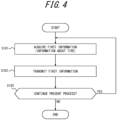
- FIG. 4 is a flowchart illustrating the operation of the first acquisition device 2. This operation corresponds to the control method of the first acquisition device 2.
- the controller 24 starts the present process, for example, when the first acquisition device 2 is powered on or when a control instruction to start the present process is received from the control device 4.
- step S102 the controller 24 transmits the acquired information about the tire 6 (first information).
- the controller 24 controls the communication section 22 to transmit the acquired information about the tire 6.
- the controller 24 may transmit a device identifier (ID) for uniquely identifying the first acquisition device 2, together with the information about the tire 6.
- ID device identifier
- the controller 24 may collectively transmit a plurality of sets of information about the tire 6 acquired during a predetermined period.
- step S103 the controller 24 determines whether to continue the present process.
- the acquisition section 31 includes one or more sensors.
- the acquisition section 31 thus acquires information about the vehicle 5.
- the acquisition section 31 includes an accelerometer.
- the acquisition section 31 acquires the acceleration of the vehicle 5 as the information about the vehicle 5.
- the sensor included in the acquisition section 31 is not limited to an accelerometer, and may be any sensor such as an angular velocity sensor.
- the acquisition section 31 may acquire information such as the angular velocity at the installation position of the second acquisition device 3 as the information about the vehicle 5 in addition to or instead of the acceleration of the vehicle 5.
- the information about the vehicle 5 is also referred to as "second information”.
- step S201 the controller 34 acquires information about the vehicle 5 (second information).
- the controller 34 acquires the acceleration of the vehicle 5 as the information about the vehicle 5 by the accelerometer included in the acquisition section 31.
- the controller 34 may store the acquired acceleration of the vehicle 5 and the acquisition time in the storage 33 as the information about the vehicle 5.
- step S203 the controller 34 determines whether to continue the present process.
- the controller 34 may determine to end the present process (i.e. not to continue the present process) in the case where a control instruction to end the present process is received from the control device 4. In the case where the controller 34 determines to continue the present process (step S203: Yes), the controller 34 repeats the present process from step S201 at predetermined time intervals. In the case where the controller 34 determines not to continue the present process (step S203: No), the controller 34 ends the present process.
- the communication section 41 includes one or more wireless communication modules.
- the wireless communication modules include communication modules compliant with communication standards such as wireless LAN and Bluetooth.
- the control device 4 can wirelessly communicate with the first acquisition device 2, the second acquisition device 3, and the like via the communication section 41.
- the communication section 41 is not limited to a wireless communication module, and may include a wired communication module such as a wired LAN communication module.
- the storage 42 is, for example, semiconductor memory, magnetic memory, or optical memory.
- the storage 42 may function, for example, as a main storage device, an auxiliary storage device, or cache memory.
- the storage 42 stores any information used for the operation of the control device 4.
- the storage 42 may store system programs, application programs, embedded software, etc.
- the controller 43 includes one or more processors. Examples of the processors include general-purpose processors such as a CPU and dedicated processors specialized for specific processing.
- the controller 43 is not limited to processors, and may include one or more dedicated circuits. Examples of the dedicated circuits include a FPGA and an ASIC.
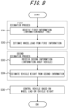
- FIG. 8 is a flowchart illustrating the operation of the control device 4. This operation corresponds to the control method of the control device 4.
- step S301 the controller 43 receives information about the tire 6 (first information).
- the controller 43 receives information about the tires 6A to 6D respectively from the first acquisition devices 2A to 2D via the communication section 41.
- the controller 43 stores the strain values of the tires 6A to 6D and their acquisition times included in the information about the tires 6A to 6D, in the storage 42.
- the controller 43 may store the information about the tires 6A to 6D in the storage 42 as time-series data.
- step S302 the controller 43 estimates the wheel load from the information about the tire 6 (first information).
- the wheel load of the tire 6 is the weight applied from the tire 6 onto the road surface with which the tire 6 contacts. That is, the wheel load of the tire 6 is the weight supported by the tire 6 out of the gross (total) weight of the vehicle 5.
- the controller 43 may store an estimation algorithm that receives the strain value of the tire 6 included in the information about the tire 6 as input and outputs the wheel load of the tire 6, in the storage 42 in advance. The controller 43 then estimates the wheel loads of the tires 6A to 6D respectively from the strain values of the tires 6A to 6D, using the estimation algorithm.
- the information about the tire 6 includes information other than the strain value
- an estimation algorithm capable of estimating the wheel load of the tire 6 may be used depending on the input information about the tire 6.
- an estimation algorithm for estimating the wheel load of the tire 6 from the acceleration or vibration frequency may be used.
- step S303 and S304 the controller 43 performs a second estimation process of estimating the vehicle weight from information about the vehicle 5 (second information).
- step S303 the controller 43 receives information about the vehicle 5 (second information).
- the controller 43 receives information about the vehicle 5 from the second acquisition device 3 via the communication section 41.
- the controller 43 stores the acceleration of the vehicle 5 and the acquisition time included in the information about the vehicle 5, in the storage 42.
- the controller 43 may store the information about the vehicle 5 in the storage 42 as time-series data.
- step S304 the controller 43 estimates the vehicle weight from the information about the vehicle 5 (second information).
- the vehicle weight is the gross weight of the vehicle 5.
- the gross weight of the vehicle 5 includes not only the weights of the vehicle body 51, tires 6, and wheels 7 but also the weights of the occupants (passengers) and cargo mounted on the vehicle 5.
- the controller 43 estimates the vehicle weight from the information about the vehicle 5 (second information) using a vehicle model.
- the vehicle model is a physical model including functions, formulas, algorithms, etc. that represent the motion or state of the vehicle 5.
- the vehicle model may be composed of the equation of motion, equation of state, etc. of the vehicle 5.
- the vehicle model may be an observer model, a statistical model, a neural network, or the like.
- the controller 43 may perform learning of the vehicle model. Specifically, the controller 43 performs machine learning, deep learning, parameter identification, or the like based on time-series data such as information representing the motion or state of the vehicle 5 or control information of the vehicle 5, to set or tune the parameters used in the vehicle model and construct or update the vehicle model.
- the vehicle model is, for example, an observer model.
- the vehicle model may be an observer model representing the relationship between the acceleration of the vehicle 5 and the output (power) of the engine.
- the controller 43 uses the vehicle model to estimate the vehicle weight of the vehicle 5 from the relationship between the acceleration of the vehicle 5 included in the information about the vehicle 5 and the current output of the engine.
- the vehicle model may be an observer model representing the relationship between the acceleration of the vehicle 5 and the degree of rotation of the steering shaft. In such a case, the controller 43 uses the vehicle model to estimate the vehicle weight of the vehicle 5 from the relationship between the acceleration of the vehicle 5 included in the information about the vehicle 5 and the current degree of rotation of the steering shaft.
- the controller 43 may use the wheel load estimated in the first estimation process, for learning the vehicle model.
- the vehicle model is an observer model
- the vehicle weight calculated from the wheel load estimated in the first estimation process may be used as an initial value of the vehicle weight of the vehicle 5 estimated by the vehicle model. This can facilitate the convergence of the observer model and shorten the time required from the start of the learning of the vehicle model to the stabilization of the output of the vehicle model.
- the information about the vehicle 5 includes information other than the acceleration
- a vehicle model capable of estimating the vehicle weight of the vehicle 5 may be used depending on the input information about the vehicle 5.
- the controller 43 may determine whether the difference between a predetermined weight A calculated using the wheel load and a predetermined weight B calculated using the vehicle weight is within a predetermined difference range.
- each of the predetermined weight A and the predetermined weight B is the vehicle weight of vehicle 5.
- the controller 43 sets the sum of the wheel loads of the tires 6A to 6D estimated in the first estimation process, as the predetermined weight A.
- the controller 43 also sets the vehicle weight of the vehicle 5 estimated in the second estimation process, as the predetermined weight B.
- the controller 43 determines whether the difference between the predetermined weight A and the predetermined weight B is within the predetermined difference range.
- the controller 43 can select one of the estimated wheel load and vehicle weight that is more suitable for controlling the vehicle 5, and use the selected information to control the vehicle 5.
- the controller 43 may perform limited vehicle control for a predetermined period after the start of the learning of the vehicle model.
- the vehicle weight of the vehicle 5 is expected to change when passengers get in or out of the vehicle or cargo is loaded or unloaded while the vehicle 5 is stopped. Accordingly, the controller 43 may perform the learning of the vehicle model at the timing when the parking brake is released in order to cause the stopped vehicle 5 to start traveling again.
- a predetermined period may be required from the start of the learning of the vehicle model to the stabilization of the output of the vehicle model, as mentioned above.
- the controller 43 therefore performs limited vehicle control for the predetermined period after the start of the learning of the vehicle model, thus improving the safety of the control of the vehicle 5 in the period during which the accuracy of the vehicle weight estimated using the vehicle model is insufficient.
- the predetermined period may be 1 minute or more and 5 minutes or less.
- the processor in the computer once stores, in memory, the program recorded in the portable recording medium or the program transferred from the certain server, and then reads the program stored in the memory and executes processes according to the read program.
- the program includes information that is to be processed by a processor and is equivalent to a program. For example, data that is not a direct command to the processor but has the property of defining the processes of the processor is "equivalent to a program".
- the vehicle model is an observer model
- the controller 43 is configured to perform the learning of the vehicle model using the wheel load.
- the control device 4 can facilitate the convergence of the observer model and shorten the time required from the start of the learning of the vehicle model to the stabilization of the output of the vehicle model.
- the structures, functions, etc. included in each embodiment or example may be rearranged without logical inconsistency.
- the structures, functions, etc. included in each embodiment may be used in combination with another embodiment or example, and a plurality of structures, functions, etc. may be combined into one structure, function, etc., one structure, function, etc. may be divided into a plurality of structures, functions, etc., or part of the structures, functions, etc. may be omitted.
- all or part of the functions or processes described as the functions or processes of the control device 4 in the foregoing embodiment may be implemented as the functions or processes of the first acquisition device 2 or the second acquisition device 3.
- a program describing the functions or processes of the control device 4 according to the embodiment may be stored in, for example, memory in the first acquisition device 2 or the second acquisition device 3, and read and executed by, for example, the processor in the first acquisition device 2 or the second acquisition device 3.
- All or part of the functions or processes described as the functions or processes of the control device 4 in the foregoing embodiment may be implemented as the functions or processes of a server installed outside the vehicle 5.
- the server may provide all or part of the functions or processes of the control device 4 as a service such as SaaS (Software as a Service).
- SaaS Software as a Service
- a server installed outside the vehicle 5 may, as the control device 4, perform all or part of the processes described above and transmit the processing result to an ECU of the vehicle 5 to indirectly control the vehicle 5.
Landscapes
- Engineering & Computer Science (AREA)
- Automation & Control Theory (AREA)
- Transportation (AREA)
- Mechanical Engineering (AREA)
- Physics & Mathematics (AREA)
- Mathematical Physics (AREA)
- Human Computer Interaction (AREA)
- Arrangements For Transmission Of Measured Signals (AREA)
- Control Of Driving Devices And Active Controlling Of Vehicle (AREA)
Applications Claiming Priority (2)
| Application Number | Priority Date | Filing Date | Title |
|---|---|---|---|
| JP2021016128A JP2022119119A (ja) | 2021-02-03 | 2021-02-03 | 車両の制御装置及び制御方法 |
| PCT/JP2021/043968 WO2022168415A1 (ja) | 2021-02-03 | 2021-11-30 | 車両の制御装置及び制御方法 |
Publications (2)
| Publication Number | Publication Date |
|---|---|
| EP4289697A1 true EP4289697A1 (en) | 2023-12-13 |
| EP4289697A4 EP4289697A4 (en) | 2024-07-17 |
Family
ID=82741115
Family Applications (1)
| Application Number | Title | Priority Date | Filing Date |
|---|---|---|---|
| EP21924800.2A Pending EP4289697A4 (en) | 2021-02-03 | 2021-11-30 | DEVICE AND METHOD FOR CONTROLLING A VEHICLE |
Country Status (5)
| Country | Link |
|---|---|
| US (1) | US20240092372A1 (ja) |
| EP (1) | EP4289697A4 (ja) |
| JP (1) | JP2022119119A (ja) |
| CN (1) | CN116829430A (ja) |
| WO (1) | WO2022168415A1 (ja) |
Family Cites Families (12)
| Publication number | Priority date | Publication date | Assignee | Title |
|---|---|---|---|---|
| JP4179016B2 (ja) * | 2003-03-26 | 2008-11-12 | トヨタ自動車株式会社 | タイヤ状態量検出システム |
| JP4300982B2 (ja) * | 2003-11-05 | 2009-07-22 | トヨタ自動車株式会社 | タイヤ状態判定装置 |
| JP2010076739A (ja) | 2008-08-25 | 2010-04-08 | Yokohama National Univ | 自動車の車両姿勢制御装置及び制御方法 |
| DE102008046269B3 (de) * | 2008-09-08 | 2009-12-24 | Continental Automotive Gmbh | Verfahren und Meßsystem zur Bestimmung einer Radlast |
| US9222854B2 (en) * | 2013-03-12 | 2015-12-29 | The Goodyear Tire & Rubber Company | Vehicle dynamic load estimation system and method |
| JP6690056B2 (ja) * | 2016-08-22 | 2020-04-28 | ぺロトン テクノロジー インコーポレイテッド | 自動連続車両の制御システムアーキテクチャ |
| WO2018161336A1 (en) * | 2017-03-10 | 2018-09-13 | Baidu.Com Times Technology (Beijing) Co., Ltd. | Automatic steering control reference adaption to resolve understeering of autonomous driving vehicles |
| JP6830873B2 (ja) * | 2017-09-11 | 2021-02-17 | 株式会社ブリヂストン | タイヤ荷重推定方法及びタイヤ荷重推定装置 |
| JP2019184412A (ja) * | 2018-04-09 | 2019-10-24 | 住友ゴム工業株式会社 | 車両の質量推定装置、方法及びプログラム |
| US11298991B2 (en) * | 2018-11-28 | 2022-04-12 | The Goodyear Tire & Rubber Company | Tire load estimation system and method |
| JP2020125964A (ja) * | 2019-02-04 | 2020-08-20 | 株式会社ショーワ | 状態量推定装置、制御装置、および状態量推定方法 |
| JP6803448B1 (ja) * | 2019-12-02 | 2020-12-23 | Toyo Tire株式会社 | 最大摩擦係数推定システムおよび最大摩擦係数推定方法 |
-
2021
- 2021-02-03 JP JP2021016128A patent/JP2022119119A/ja active Pending
- 2021-11-30 CN CN202180092849.4A patent/CN116829430A/zh active Pending
- 2021-11-30 US US18/262,886 patent/US20240092372A1/en active Pending
- 2021-11-30 EP EP21924800.2A patent/EP4289697A4/en active Pending
- 2021-11-30 WO PCT/JP2021/043968 patent/WO2022168415A1/ja active Application Filing
Also Published As
| Publication number | Publication date |
|---|---|
| WO2022168415A1 (ja) | 2022-08-11 |
| JP2022119119A (ja) | 2022-08-16 |
| US20240092372A1 (en) | 2024-03-21 |
| EP4289697A4 (en) | 2024-07-17 |
| CN116829430A (zh) | 2023-09-29 |
Similar Documents
| Publication | Publication Date | Title |
|---|---|---|
| US11573119B2 (en) | Method and apparatus for dynamically estimating vehicle mass | |
| US8983722B2 (en) | System and method for vehicle rollover prediction | |
| US20210008933A1 (en) | Method, control device, and system for determining a profile depth of a profile of a tire | |
| JP2010066261A (ja) | 車輪荷重を検出するための方法および測定システム | |
| CN110446619B (zh) | 用于确定车辆车轮上的车轮载荷的方法和设备 | |
| CN111008121A (zh) | 车辆软件检查 | |
| CN112277849A (zh) | 车辆关闭状态期间的电力供应 | |
| JP2023540204A (ja) | 温度上昇データを使用する車両タイヤ位置特定システム及び方法 | |
| JP2007126056A (ja) | 車両挙動制御装置及びスタビリティファクタ予想装置 | |
| CN112277922A (zh) | 车辆起动期间的电力供应 | |
| CN115402279A (zh) | 用于找到挂车制动最佳增益的基于车辆的算法 | |
| EP4289697A1 (en) | Device and method for controlling vehicle | |
| US11230294B2 (en) | Vehicle speed estimation system | |
| CN117901871A (zh) | 使用车轮传感器数据的驾驶模式自适应系统和方法 | |
| CN112631645A (zh) | 车辆软件检查 | |
| CN115071680B (zh) | 车辆驾驶辅助横向控制系统安全限制方法及可读存储介质 | |
| JP7492909B2 (ja) | タイヤ状態監視システム、受信機、及び送信機 | |
| US11724689B2 (en) | Systems and methods for predicting and detecting vehicle instability | |
| JP2005140503A (ja) | 車両用ホイールおよび車両の負荷監視装置 | |
| CN111600514B (zh) | 用于防止转矩波动的电动马达控制 | |
| US11097727B2 (en) | Eco-cruise: torque management | |
| EP4404172A1 (en) | Information processing device, information processing method, program, driving control device, driving control method, and program | |
| JP7345682B2 (ja) | 車上制御装置および加速度センサ診断方法 | |
| EP4339020A1 (en) | Method and device for detecting vehicle loading abnormality | |
| US20240227467A1 (en) | Method for controlling a tire pressure monitoring system |
Legal Events
| Date | Code | Title | Description |
|---|---|---|---|
| STAA | Information on the status of an ep patent application or granted ep patent |
Free format text: STATUS: THE INTERNATIONAL PUBLICATION HAS BEEN MADE |
|
| PUAI | Public reference made under article 153(3) epc to a published international application that has entered the european phase |
Free format text: ORIGINAL CODE: 0009012 |
|
| STAA | Information on the status of an ep patent application or granted ep patent |
Free format text: STATUS: REQUEST FOR EXAMINATION WAS MADE |
|
| 17P | Request for examination filed |
Effective date: 20230714 |
|
| AK | Designated contracting states |
Kind code of ref document: A1 Designated state(s): AL AT BE BG CH CY CZ DE DK EE ES FI FR GB GR HR HU IE IS IT LI LT LU LV MC MK MT NL NO PL PT RO RS SE SI SK SM TR |
|
| DAV | Request for validation of the european patent (deleted) | ||
| DAX | Request for extension of the european patent (deleted) | ||
| A4 | Supplementary search report drawn up and despatched |
Effective date: 20240617 |
|
| RIC1 | Information provided on ipc code assigned before grant |
Ipc: B60W 50/00 20060101ALI20240611BHEP Ipc: B60W 30/14 20060101ALI20240611BHEP Ipc: B60W 60/00 20200101ALI20240611BHEP Ipc: B60W 40/13 20120101AFI20240611BHEP |