EP4289637B1 - Hitzeschildplattenhalterung - Google Patents
Hitzeschildplattenhalterung Download PDFInfo
- Publication number
- EP4289637B1 EP4289637B1 EP22461569.0A EP22461569A EP4289637B1 EP 4289637 B1 EP4289637 B1 EP 4289637B1 EP 22461569 A EP22461569 A EP 22461569A EP 4289637 B1 EP4289637 B1 EP 4289637B1
- Authority
- EP
- European Patent Office
- Prior art keywords
- retainer
- heat shield
- panel
- panels
- wheel
- Prior art date
- Legal status (The legal status is an assumption and is not a legal conclusion. Google has not performed a legal analysis and makes no representation as to the accuracy of the status listed.)
- Active
Links
Images
Classifications
-
- B—PERFORMING OPERATIONS; TRANSPORTING
- B60—VEHICLES IN GENERAL
- B60C—VEHICLE TYRES; TYRE INFLATION; TYRE CHANGING; CONNECTING VALVES TO INFLATABLE ELASTIC BODIES IN GENERAL; DEVICES OR ARRANGEMENTS RELATED TO TYRES
- B60C23/00—Devices for measuring, signalling, controlling, or distributing tyre pressure or temperature, specially adapted for mounting on vehicles; Arrangement of tyre inflating devices on vehicles, e.g. of pumps or of tanks; Tyre cooling arrangements
- B60C23/18—Tyre cooling arrangements, e.g. heat shields
-
- B—PERFORMING OPERATIONS; TRANSPORTING
- B64—AIRCRAFT; AVIATION; COSMONAUTICS
- B64C—AEROPLANES; HELICOPTERS
- B64C25/00—Alighting gear
- B64C25/32—Alighting gear characterised by elements which contact the ground or similar surface
- B64C25/34—Alighting gear characterised by elements which contact the ground or similar surface wheeled type, e.g. multi-wheeled bogies
- B64C25/36—Arrangements or adaptations of wheels, tyres or axles in general
-
- F—MECHANICAL ENGINEERING; LIGHTING; HEATING; WEAPONS; BLASTING
- F16—ENGINEERING ELEMENTS AND UNITS; GENERAL MEASURES FOR PRODUCING AND MAINTAINING EFFECTIVE FUNCTIONING OF MACHINES OR INSTALLATIONS; THERMAL INSULATION IN GENERAL
- F16D—COUPLINGS FOR TRANSMITTING ROTATION; CLUTCHES; BRAKES
- F16D55/00—Brakes with substantially-radial braking surfaces pressed together in axial direction, e.g. disc brakes
- F16D55/24—Brakes with substantially-radial braking surfaces pressed together in axial direction, e.g. disc brakes with a plurality of axially-movable discs, lamellae, or pads, pressed from one side towards an axially-located member
- F16D55/26—Brakes with substantially-radial braking surfaces pressed together in axial direction, e.g. disc brakes with a plurality of axially-movable discs, lamellae, or pads, pressed from one side towards an axially-located member without self-tightening action
- F16D55/36—Brakes with a plurality of rotating discs all lying side by side
-
- F—MECHANICAL ENGINEERING; LIGHTING; HEATING; WEAPONS; BLASTING
- F16—ENGINEERING ELEMENTS AND UNITS; GENERAL MEASURES FOR PRODUCING AND MAINTAINING EFFECTIVE FUNCTIONING OF MACHINES OR INSTALLATIONS; THERMAL INSULATION IN GENERAL
- F16D—COUPLINGS FOR TRANSMITTING ROTATION; CLUTCHES; BRAKES
- F16D65/00—Parts or details
- F16D65/02—Braking members; Mounting thereof
- F16D65/12—Discs; Drums for disc brakes
- F16D65/128—Discs; Drums for disc brakes characterised by means for cooling
-
- F—MECHANICAL ENGINEERING; LIGHTING; HEATING; WEAPONS; BLASTING
- F16—ENGINEERING ELEMENTS AND UNITS; GENERAL MEASURES FOR PRODUCING AND MAINTAINING EFFECTIVE FUNCTIONING OF MACHINES OR INSTALLATIONS; THERMAL INSULATION IN GENERAL
- F16D—COUPLINGS FOR TRANSMITTING ROTATION; CLUTCHES; BRAKES
- F16D65/00—Parts or details
- F16D65/78—Features relating to cooling
- F16D2065/785—Heat insulation or reflection
-
- F—MECHANICAL ENGINEERING; LIGHTING; HEATING; WEAPONS; BLASTING
- F16—ENGINEERING ELEMENTS AND UNITS; GENERAL MEASURES FOR PRODUCING AND MAINTAINING EFFECTIVE FUNCTIONING OF MACHINES OR INSTALLATIONS; THERMAL INSULATION IN GENERAL
- F16D—COUPLINGS FOR TRANSMITTING ROTATION; CLUTCHES; BRAKES
- F16D65/00—Parts or details
- F16D65/78—Features relating to cooling
- F16D65/84—Features relating to cooling for disc brakes
- F16D65/847—Features relating to cooling for disc brakes with open cooling system, e.g. cooled by air
Definitions
- the present invention relates to a retainer for connecting panels or segments of a heat shield assembly for a wheel for a vehicle especially, but not exclusively, for an aircraft wheel.
- Wheels on aircraft and other vehicles are often provided with a brake assembly comprising a stack of brake discs mounted inside the wheel, within the tube well of the wheel.
- the brake operates by compressing the brake discs together to slow and stop rotation of the wheel.
- the friction between the pressed brake discs generates a large amount of heat which can cause damage to the wheel and/or tyres.
- the heat shield can also catch hot brake material that is ejected from the brake discs during braking, before it strikes the wheel.
- heat shields are in the form of metal sheets or panels provided concentric with the wheel tube well and spaced a small distance from the tube well.
- the heat shield can be provided as a single cylindrical piece but more typically is formed as a number of arcuate panels or segments that are attached together to form a complete cylindrical heat shield.
- EP3712061A shows an example of a retainer.
- Heat shields are therefore, often made of thin metal panels but may be arranged as two or more layers of panels with an insulation gap therebetween.
- the heat shield can be caused to deform and/or deflect. This can cause high stresses on the heat shield and can cause the heat shield to come into contact with the wheel tube well which can, in turn, result in wheel abrasion.
- the connectors used to join adjacent panels comprise two engaging or interleaving hook parts resulting in a seam that is thicker than the individual panels themselves and the seams provide points around the heat shield that are even more likely to contact the wheel tube well during movement and/or if the heat shield panels are deflected or deformed.
- Flatter retainers have also been designed, that take the form of a central panel and side wings or panels.
- the central panel is provided with a hole at the top end through which a bolt can pass, and a foot at the bottom to be supported by a torque bar.
- the side panels extend partly across respective adjacent heat shield panels.
- the retainer and torque bar combine to connect/retain the heat shield panels.
- Such retainers are made of relatively thin sheets of metal to maintain a low profile.
- the retainer being thin, provides an area of weakness in the heat shield assembly, and is the area where the greatest deflection and plasticity appears.
- the retainer may not be strong enough to prevent deflection of the wings and the heat shield panels they support, in certain conditions. This can therefore lead to the heat shield panels making contact with the tube well, thus resulting in abrasion.
- a retainer for connecting two panels of a heat shield assembly comprising: a central elongate panel having a length I and a width w, a top end, a bottom end and first and second long sides extending from the top end to the bottom end; a first side panel extending along the first long side of the central elongate panel and a second side panel extending along the second long side of the central elongate panel; and characterized in that the central elongate panel is corrugated, with corrugations running along the length of the central elongate panel from the top end to the bottom end.
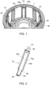
- Figure 1 shows a section of a typical wheel assembly comprising a wheel rim or tube well 1 having an outer diameter surface 10, on which a tyre (not shown) will usually be mounted, and an inner diameter surface 20 defining an interior cavity in which a brake assembly (not shown) will typically be arranged around a wheel hub 30.
- the hub 30 would be attached by bearing to an axle (not shown).
- the hub 30 is connected to the wheel rim 1 via a web 40.
- Rotor disc drive lugs (or torque bars) 50 extend axially across the tube well 1 for engagement with the brake discs.
- a heat shield is mounted to the inner diameter surface 20 of the wheel.
- the heat shield may be a single tubular shield or, as shown in this example, may be formed of several heat shield panels 60 provided between the rotor drive lugs 50.
- the heat shield/panels 60 is in the form of an arcuate thin metal sheet or several thin metal sheets and is attached to the wheel so as to be spaced apart from the wheel inner diameter surface by a small insulation gap (not shown).
- the heat shield is made of a number of panels or segments attached together, the adjoining edges 60a, 60b of the panels are connected and retained by means of retainers 70.
- the retainers 70 each define a seam between adjacent panels.
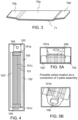
- a typical retainer 70 is shown in Figs. 2 and 3 .
- Such a retainer 70 is formed of a shaped metal sheet having a main panel 70a that, in use, will define the seam between two adjacent heat shield panels when positioned between their adjacent edges 60a, 60b.
- the main panel 70a has a length I and a width w essentially corresponding to the dimensions of a drive lug 50.
- the top of the main panel is provided with a tab 61 within which is formed a hole 62 to receive a bolt or fastener (not shown).
- the other end of the main panel is provided with a foot 63 to support the retainer in place against the lug 50.
- the foot 63 may also have a hole 65 therethrough, in which an end pin of the lug can be located.
- cut-outs 66 are formed between the main panel and the foot. Extending along each of the long sides of the main panel is a side panel or wing 70b, 70b'. A bend 71 provides the transition from the main panel 70a to the wing 70b, 70b'.
- the retainer is located between adjacent edges of adjacent heat shield segments such that the wings extend over part of the respective segment to retain the segments to form the circular heat shield at the appropriate distance from the tube well.
- Figure 4 shows a retainer 100 modified according to the disclosure to add stiffness and strength to the heat shield whilst minimising the thickness of the retainer in the space between the heat shield and the wheel, so reducing the effects of deformation or deflection of the panel, to avoid or mitigate the problems mentioned above.
- the shape of the retainer is similar to that shown in Figs. 2 and 3 in that the retainer 100 is formed of a sheet of metal shaped to define an elongate central panel 101 flanked by two side panels or wings 102, 102'. Similarly to the known design, one end of the central panel is provided with a tab 103 through which a fastener hole 104 may be formed and the other end of the central panel is formed as a foot 105 which may have a hole 106 therethrough to retain a torque bar (not shown).
- the central panel is corrugated as best seen in Figs. 5A and 5B .
- the corrugations 200 run along the full length of the retainer, from the top end to the bottom end, which significantly adds to the strength and stiffness of the retainer.
- the retainer can be formed as a single piece, it is possible to form the retainer as three separate parts, as can be seen in Figs. 5A and 5B , whereby a top end portion 101a of the corrugated central elongate panel is formed as one part with the tab 103, and a bottom end part 101b of the central elongate panel is formed in a part with the foot 106, and these parts are then attached e.g. by welding, to the middle part 101c of the central elongate panel.
- the corrugated form increases the surface area of the retainer and so improves its thermal properties.
- the number of corrugations can be increased or decreased.
- the central panel 101 is located at the seam between adjoining edges of adjacent panels and the side panels 102, 102; extend partially across the respective heat shield panel to retain the heat shield panels in the heat shield configuration and spaced from the tube well by the insulation gap.
- the retainer With the added stiffness and strength provided by the corrugations, if the heat shield panels deflect, the retainer will be strong and stiff enough to retain the heat shield panels away from the inner diameter of the tube well without the retainer or the heat shield panels contacting the wheel and causing abrasion.
- the corrugations combine to increase the stiffness of the retainer, and so the depth of each individual corrugation can still be relatively small.
- the retainers in the space between the heat shield and the wheel rim therefore, have a relatively small profile and are thus less likely to contact the wheel rim if the panel is deformed or deflected than in conventional assemblies.
- the depth d of the corrugations 200 is approximately the same as the distance by which the foot 106 extends radially inwards.
- the modified retainer does not, therefore, take up any additional space compared to the known design.
- each pair of adjacent heat shield panels is provided with a retainer between their adjoining edges.
- two or more retainers may be positioned between each pair of heat shield panels.
- the retainer of this invention provides additional strength to the heat shield and a secure connection between heat shield panels, whilst minimising the risk of wheel abrasion due to deformation or deflection of the panels.
Landscapes
- Engineering & Computer Science (AREA)
- Mechanical Engineering (AREA)
- General Engineering & Computer Science (AREA)
- Aviation & Aerospace Engineering (AREA)
- Braking Arrangements (AREA)
Claims (13)
- Halterung zum Verbinden von zwei Platten einer Hitzeschildbaugruppe, wobei die Halterung Folgendes umfasst: eine zentrale längliche Platte (101), die eine Länge l und eine Breite w, ein oberes Ende, ein unteres Ende und eine erste und zweite Längsseite, die sich von dem oberen Ende zu dem unteren Ende erstrecken, aufweist; eine erste Seitenplatte (102), die sich entlang der ersten Längsseite der zentralen länglichen Platte erstreckt, und eine zweite Seitenplatte (102'), die sich entlang der zweiten Längsseite der zentralen länglichen Platte erstreckt; und dadurch gekennzeichnet, dass die zentrale längliche Platte gewellt ist, wobei die Wellungen von dem oberen Ende entlang der Länge der zentralen länglichen Platte zu dem unteren Ende verlaufen.
- Halterung nach Anspruch 1, ferner umfassend eine Lasche (103), die sich von dem oberen Ende erstreckt.
- Halterung nach Anspruch 2, ferner umfassend ein in der Lasche (103) ausgebildetes Befestigungsloch (104).
- Halterung nach einem der vorhergehenden Ansprüche, ferner umfassend ein Fußteil (105) an dem unteren Ende.
- Halterung nach Anspruch 4, ferner umfassend ein Positionierungsloch (106) in dem Fußteil (105).
- Halterung nach einem der vorhergehenden Ansprüche, wobei die zentrale Platte und die erste und zweite Seitenplatte aus einem einzigen Stück Blech ausgebildet sind.
- Halterung nach einem der Ansprüche 1 bis 5, wobei die Halterung aus einem oberen Abschnitt, einem mittleren Abschnitt und einem unteren Abschnitt ausgebildet ist, wobei der obere Abschnitt an ein Ende des mittleren Abschnitts geschweißt ist und der untere Abschnitt an das andere Ende des mittleren Abschnitts geschweißt ist.
- Hitzeschildbaugruppe für eine Radbaugruppe, umfassend eine Vielzahl von bogenförmigen Hitzeschildplatten (60), die angeordnet ist, um unter Ausbilden eines Hitzeschilds, der an der Innenseite eines Rades anzubringen ist, miteinander verbunden zu werden, und eine Halterung nach einem der vorhergehenden Ansprüche zum Anbringen benachbarter Platten.
- Hitzeschildbaugruppe nach Anspruch 8, wobei zwischen jedem Paar von benachbarten Platten eine oder mehrere Halterungen bereitgestellt sind.
- Hitzeschildbaugruppe nach Anspruch 8 oder 9, wobei jede Platte zwei radial benachbart zueinander angeordnete Hitzeschildplattenschichten umfasst und wobei eine Halterung eine relative Bewegung der Schichten verhindert.
- Radbaugruppe, umfassend eine Radfelge, die eine radial innere Fläche und eine radial äußere Fläche aufweist, und eine Hitzeschildbaugruppe nach Anspruch 8, 9 oder 10, die an der Radfelge angebracht ist und eine radial äußere Fläche aufweist, die radial von der radial inneren Fläche der Radfelge beabstandet ist.
- Radbaugruppe nach Anspruch 11, ferner umfassend eine Vielzahl von Drehmomentstäben (50), die um die radial innere Fläche des Hitzeschildes herum angeordnet ist, wobei ein Drehmomentstab entlang der zentralen länglichen Platte jeder Halterung positioniert ist.
- Radbaugruppe nach Anspruch 11 oder 12, wobei es sich um eine Radbaugruppe für das Fahrwerk eines Luftfahrzeugs handelt.
Priority Applications (2)
| Application Number | Priority Date | Filing Date | Title |
|---|---|---|---|
| EP22461569.0A EP4289637B1 (de) | 2022-06-09 | 2022-06-09 | Hitzeschildplattenhalterung |
| US18/325,763 US20230398818A1 (en) | 2022-06-09 | 2023-05-30 | Heat shield panel retainer |
Applications Claiming Priority (1)
| Application Number | Priority Date | Filing Date | Title |
|---|---|---|---|
| EP22461569.0A EP4289637B1 (de) | 2022-06-09 | 2022-06-09 | Hitzeschildplattenhalterung |
Publications (2)
| Publication Number | Publication Date |
|---|---|
| EP4289637A1 EP4289637A1 (de) | 2023-12-13 |
| EP4289637B1 true EP4289637B1 (de) | 2025-02-19 |
Family
ID=82019689
Family Applications (1)
| Application Number | Title | Priority Date | Filing Date |
|---|---|---|---|
| EP22461569.0A Active EP4289637B1 (de) | 2022-06-09 | 2022-06-09 | Hitzeschildplattenhalterung |
Country Status (2)
| Country | Link |
|---|---|
| US (1) | US20230398818A1 (de) |
| EP (1) | EP4289637B1 (de) |
Families Citing this family (1)
| Publication number | Priority date | Publication date | Assignee | Title |
|---|---|---|---|---|
| EP4289638A1 (de) * | 2022-06-09 | 2023-12-13 | Goodrich Corporation | Hitzeschildplattenhalterung |
Family Cites Families (9)
| Publication number | Priority date | Publication date | Assignee | Title |
|---|---|---|---|---|
| US1961486A (en) * | 1927-07-20 | 1934-06-05 | Duluth Show Case Company | Holding clip for partition plates and the like |
| US4017123A (en) * | 1976-04-02 | 1977-04-12 | The Bendix Corporation | Dual layer heat shield for wheels |
| US4084857A (en) * | 1976-12-20 | 1978-04-18 | The Bendix Corporation | Drive key heat shield and support for wheel rim heat shield of multiple disc brake |
| US5851056A (en) * | 1996-06-03 | 1998-12-22 | The B. F. Goodrich Company | Aircraft brake heat shield having easily removed heat shield sections |
| DE60218355T2 (de) * | 2001-10-10 | 2007-10-31 | Goodrich Corp. | Bremsanordnung mit einem Hitzeschild in einem Flugzeugrad |
| US11346418B2 (en) * | 2019-03-19 | 2022-05-31 | Goodrich Corporation | Covered retainer for segmented annular heat shield |
| US11713111B2 (en) * | 2019-03-19 | 2023-08-01 | Goodrich Corporation | Retainer for segmented annular heat shield |
| US11274715B2 (en) * | 2019-07-16 | 2022-03-15 | Goodrich Corporation | Heat shield retainer and methods |
| US12017487B2 (en) * | 2020-12-09 | 2024-06-25 | Goodrich Corporation | Wheel assembly with torque bar bracket ribs |
-
2022
- 2022-06-09 EP EP22461569.0A patent/EP4289637B1/de active Active
-
2023
- 2023-05-30 US US18/325,763 patent/US20230398818A1/en active Pending
Also Published As
| Publication number | Publication date |
|---|---|
| US20230398818A1 (en) | 2023-12-14 |
| EP4289637A1 (de) | 2023-12-13 |
Similar Documents
| Publication | Publication Date | Title |
|---|---|---|
| EP0555822B1 (de) | Wärmeschutzschild-Vorrichtung für Flugzeugbremse | |
| EP3521161B1 (de) | Metallischer hitzeschild mit laminierte folie mit warzen | |
| EP3647622B1 (de) | Segmentierter hitzeschild mit reduzierter zwischenschichtwärmeleitung | |
| EP4289637B1 (de) | Hitzeschildplattenhalterung | |
| US20190093719A1 (en) | Disc brakes and braking systems | |
| EP4289636B1 (de) | Hitzeschildplattenhalterung | |
| US12459312B2 (en) | Heat shield panel retainer | |
| US9709110B2 (en) | Brake disc ventilation arrangement | |
| EP4417833B1 (de) | Hitzeschildanordnung | |
| US12486028B2 (en) | Heat shield panel connector | |
| EP4321769B1 (de) | Hitzeschildtafel | |
| EP4155571B1 (de) | Befestigungsklammer für ein hitzeschildpaneel | |
| EP3404283B1 (de) | Torsionsrohr | |
| EP4155572B1 (de) | Hitzeschildanordnung für ein rad und rad mit einer hitzeschildanordnung | |
| US12498008B2 (en) | Rotor clip for brake assembly | |
| EP4155570B1 (de) | Rotorclip für bremsenanordnung | |
| EP4403790A1 (de) | Hitzeschildanordnung | |
| US4000791A (en) | Disk brake for reinforced drive key member | |
| EP4290093B1 (de) | Rotorclip für bremsenanordnung |
Legal Events
| Date | Code | Title | Description |
|---|---|---|---|
| PUAI | Public reference made under article 153(3) epc to a published international application that has entered the european phase |
Free format text: ORIGINAL CODE: 0009012 |
|
| STAA | Information on the status of an ep patent application or granted ep patent |
Free format text: STATUS: THE APPLICATION HAS BEEN PUBLISHED |
|
| AK | Designated contracting states |
Kind code of ref document: A1 Designated state(s): AL AT BE BG CH CY CZ DE DK EE ES FI FR GB GR HR HU IE IS IT LI LT LU LV MC MK MT NL NO PL PT RO RS SE SI SK SM TR |
|
| STAA | Information on the status of an ep patent application or granted ep patent |
Free format text: STATUS: REQUEST FOR EXAMINATION WAS MADE |
|
| 17P | Request for examination filed |
Effective date: 20240611 |
|
| RBV | Designated contracting states (corrected) |
Designated state(s): AL AT BE BG CH CY CZ DE DK EE ES FI FR GB GR HR HU IE IS IT LI LT LU LV MC MK MT NL NO PL PT RO RS SE SI SK SM TR |
|
| RIC1 | Information provided on ipc code assigned before grant |
Ipc: F16D 65/847 20060101ALI20240828BHEP Ipc: F16D 65/78 20060101ALI20240828BHEP Ipc: F16D 55/36 20060101ALI20240828BHEP Ipc: B60C 23/18 20060101AFI20240828BHEP |
|
| GRAP | Despatch of communication of intention to grant a patent |
Free format text: ORIGINAL CODE: EPIDOSNIGR1 |
|
| STAA | Information on the status of an ep patent application or granted ep patent |
Free format text: STATUS: GRANT OF PATENT IS INTENDED |
|
| INTG | Intention to grant announced |
Effective date: 20241009 |
|
| RIN1 | Information on inventor provided before grant (corrected) |
Inventor name: SOSNOWSKI, MIROS AW Inventor name: MILLER, JERRY Inventor name: STEVENSON, JOHN A. Inventor name: HERRMANN, NATHANIEL Inventor name: ZUK, BARTLOMIEJ Inventor name: SOKOLOWSKI, MARCIN |
|
| GRAS | Grant fee paid |
Free format text: ORIGINAL CODE: EPIDOSNIGR3 |
|
| GRAA | (expected) grant |
Free format text: ORIGINAL CODE: 0009210 |
|
| STAA | Information on the status of an ep patent application or granted ep patent |
Free format text: STATUS: THE PATENT HAS BEEN GRANTED |
|
| AK | Designated contracting states |
Kind code of ref document: B1 Designated state(s): AL AT BE BG CH CY CZ DE DK EE ES FI FR GB GR HR HU IE IS IT LI LT LU LV MC MK MT NL NO PL PT RO RS SE SI SK SM TR |
|
| REG | Reference to a national code |
Ref country code: GB Ref legal event code: FG4D |
|
| REG | Reference to a national code |
Ref country code: CH Ref legal event code: EP |
|
| REG | Reference to a national code |
Ref country code: DE Ref legal event code: R096 Ref document number: 602022010815 Country of ref document: DE |
|
| REG | Reference to a national code |
Ref country code: IE Ref legal event code: FG4D |
|
| REG | Reference to a national code |
Ref country code: NL Ref legal event code: MP Effective date: 20250219 |
|
| PG25 | Lapsed in a contracting state [announced via postgrant information from national office to epo] |
Ref country code: RS Free format text: LAPSE BECAUSE OF FAILURE TO SUBMIT A TRANSLATION OF THE DESCRIPTION OR TO PAY THE FEE WITHIN THE PRESCRIBED TIME-LIMIT Effective date: 20250519 |
|
| PG25 | Lapsed in a contracting state [announced via postgrant information from national office to epo] |
Ref country code: FI Free format text: LAPSE BECAUSE OF FAILURE TO SUBMIT A TRANSLATION OF THE DESCRIPTION OR TO PAY THE FEE WITHIN THE PRESCRIBED TIME-LIMIT Effective date: 20250219 |
|
| PG25 | Lapsed in a contracting state [announced via postgrant information from national office to epo] |
Ref country code: PL Free format text: LAPSE BECAUSE OF FAILURE TO SUBMIT A TRANSLATION OF THE DESCRIPTION OR TO PAY THE FEE WITHIN THE PRESCRIBED TIME-LIMIT Effective date: 20250219 |
|
| PG25 | Lapsed in a contracting state [announced via postgrant information from national office to epo] |
Ref country code: ES Free format text: LAPSE BECAUSE OF FAILURE TO SUBMIT A TRANSLATION OF THE DESCRIPTION OR TO PAY THE FEE WITHIN THE PRESCRIBED TIME-LIMIT Effective date: 20250219 |
|
| REG | Reference to a national code |
Ref country code: LT Ref legal event code: MG9D |
|
| PG25 | Lapsed in a contracting state [announced via postgrant information from national office to epo] |
Ref country code: IS Free format text: LAPSE BECAUSE OF FAILURE TO SUBMIT A TRANSLATION OF THE DESCRIPTION OR TO PAY THE FEE WITHIN THE PRESCRIBED TIME-LIMIT Effective date: 20250619 Ref country code: NO Free format text: LAPSE BECAUSE OF FAILURE TO SUBMIT A TRANSLATION OF THE DESCRIPTION OR TO PAY THE FEE WITHIN THE PRESCRIBED TIME-LIMIT Effective date: 20250519 |
|
| PG25 | Lapsed in a contracting state [announced via postgrant information from national office to epo] |
Ref country code: NL Free format text: LAPSE BECAUSE OF FAILURE TO SUBMIT A TRANSLATION OF THE DESCRIPTION OR TO PAY THE FEE WITHIN THE PRESCRIBED TIME-LIMIT Effective date: 20250219 |
|
| PG25 | Lapsed in a contracting state [announced via postgrant information from national office to epo] |
Ref country code: HR Free format text: LAPSE BECAUSE OF FAILURE TO SUBMIT A TRANSLATION OF THE DESCRIPTION OR TO PAY THE FEE WITHIN THE PRESCRIBED TIME-LIMIT Effective date: 20250219 |
|
| PG25 | Lapsed in a contracting state [announced via postgrant information from national office to epo] |
Ref country code: PT Free format text: LAPSE BECAUSE OF FAILURE TO SUBMIT A TRANSLATION OF THE DESCRIPTION OR TO PAY THE FEE WITHIN THE PRESCRIBED TIME-LIMIT Effective date: 20250620 Ref country code: LV Free format text: LAPSE BECAUSE OF FAILURE TO SUBMIT A TRANSLATION OF THE DESCRIPTION OR TO PAY THE FEE WITHIN THE PRESCRIBED TIME-LIMIT Effective date: 20250219 |
|
| PGFP | Annual fee paid to national office [announced via postgrant information from national office to epo] |
Ref country code: FR Payment date: 20250520 Year of fee payment: 4 |
|
| PG25 | Lapsed in a contracting state [announced via postgrant information from national office to epo] |
Ref country code: BG Free format text: LAPSE BECAUSE OF FAILURE TO SUBMIT A TRANSLATION OF THE DESCRIPTION OR TO PAY THE FEE WITHIN THE PRESCRIBED TIME-LIMIT Effective date: 20250219 Ref country code: GR Free format text: LAPSE BECAUSE OF FAILURE TO SUBMIT A TRANSLATION OF THE DESCRIPTION OR TO PAY THE FEE WITHIN THE PRESCRIBED TIME-LIMIT Effective date: 20250520 |
|
| REG | Reference to a national code |
Ref country code: AT Ref legal event code: MK05 Ref document number: 1767983 Country of ref document: AT Kind code of ref document: T Effective date: 20250219 |
|
| PG25 | Lapsed in a contracting state [announced via postgrant information from national office to epo] |
Ref country code: SE Free format text: LAPSE BECAUSE OF FAILURE TO SUBMIT A TRANSLATION OF THE DESCRIPTION OR TO PAY THE FEE WITHIN THE PRESCRIBED TIME-LIMIT Effective date: 20250219 |
|
| PG25 | Lapsed in a contracting state [announced via postgrant information from national office to epo] |
Ref country code: SM Free format text: LAPSE BECAUSE OF FAILURE TO SUBMIT A TRANSLATION OF THE DESCRIPTION OR TO PAY THE FEE WITHIN THE PRESCRIBED TIME-LIMIT Effective date: 20250219 |
|
| PG25 | Lapsed in a contracting state [announced via postgrant information from national office to epo] |
Ref country code: DK Free format text: LAPSE BECAUSE OF FAILURE TO SUBMIT A TRANSLATION OF THE DESCRIPTION OR TO PAY THE FEE WITHIN THE PRESCRIBED TIME-LIMIT Effective date: 20250219 |
|
| PG25 | Lapsed in a contracting state [announced via postgrant information from national office to epo] |
Ref country code: IT Free format text: LAPSE BECAUSE OF FAILURE TO SUBMIT A TRANSLATION OF THE DESCRIPTION OR TO PAY THE FEE WITHIN THE PRESCRIBED TIME-LIMIT Effective date: 20250219 |
|
| PG25 | Lapsed in a contracting state [announced via postgrant information from national office to epo] |
Ref country code: AT Free format text: LAPSE BECAUSE OF FAILURE TO SUBMIT A TRANSLATION OF THE DESCRIPTION OR TO PAY THE FEE WITHIN THE PRESCRIBED TIME-LIMIT Effective date: 20250219 |
|
| PG25 | Lapsed in a contracting state [announced via postgrant information from national office to epo] |
Ref country code: EE Free format text: LAPSE BECAUSE OF FAILURE TO SUBMIT A TRANSLATION OF THE DESCRIPTION OR TO PAY THE FEE WITHIN THE PRESCRIBED TIME-LIMIT Effective date: 20250219 Ref country code: CZ Free format text: LAPSE BECAUSE OF FAILURE TO SUBMIT A TRANSLATION OF THE DESCRIPTION OR TO PAY THE FEE WITHIN THE PRESCRIBED TIME-LIMIT Effective date: 20250219 |
|
| PG25 | Lapsed in a contracting state [announced via postgrant information from national office to epo] |
Ref country code: RO Free format text: LAPSE BECAUSE OF FAILURE TO SUBMIT A TRANSLATION OF THE DESCRIPTION OR TO PAY THE FEE WITHIN THE PRESCRIBED TIME-LIMIT Effective date: 20250219 |
|
| PG25 | Lapsed in a contracting state [announced via postgrant information from national office to epo] |
Ref country code: SK Free format text: LAPSE BECAUSE OF FAILURE TO SUBMIT A TRANSLATION OF THE DESCRIPTION OR TO PAY THE FEE WITHIN THE PRESCRIBED TIME-LIMIT Effective date: 20250219 |
|
| REG | Reference to a national code |
Ref country code: DE Ref legal event code: R097 Ref document number: 602022010815 Country of ref document: DE |
|
| PLBE | No opposition filed within time limit |
Free format text: ORIGINAL CODE: 0009261 |
|
| STAA | Information on the status of an ep patent application or granted ep patent |
Free format text: STATUS: NO OPPOSITION FILED WITHIN TIME LIMIT |
|
| REG | Reference to a national code |
Ref country code: CH Ref legal event code: L10 Free format text: ST27 STATUS EVENT CODE: U-0-0-L10-L00 (AS PROVIDED BY THE NATIONAL OFFICE) Effective date: 20251231 |
|
| REG | Reference to a national code |
Ref country code: CH Ref legal event code: H13 Free format text: ST27 STATUS EVENT CODE: U-0-0-H10-H13 (AS PROVIDED BY THE NATIONAL OFFICE) Effective date: 20260127 |
|
| 26N | No opposition filed |
Effective date: 20251120 |
|
| PG25 | Lapsed in a contracting state [announced via postgrant information from national office to epo] |
Ref country code: MC Free format text: LAPSE BECAUSE OF FAILURE TO SUBMIT A TRANSLATION OF THE DESCRIPTION OR TO PAY THE FEE WITHIN THE PRESCRIBED TIME-LIMIT Effective date: 20250219 |