EP4403790A1 - Hitzeschildanordnung - Google Patents
Hitzeschildanordnung Download PDFInfo
- Publication number
- EP4403790A1 EP4403790A1 EP23461503.7A EP23461503A EP4403790A1 EP 4403790 A1 EP4403790 A1 EP 4403790A1 EP 23461503 A EP23461503 A EP 23461503A EP 4403790 A1 EP4403790 A1 EP 4403790A1
- Authority
- EP
- European Patent Office
- Prior art keywords
- heat shield
- overlap
- flanges
- rotor
- components
- Prior art date
- Legal status (The legal status is an assumption and is not a legal conclusion. Google has not performed a legal analysis and makes no representation as to the accuracy of the status listed.)
- Pending
Links
Images


Classifications
-
- F—MECHANICAL ENGINEERING; LIGHTING; HEATING; WEAPONS; BLASTING
- F16—ENGINEERING ELEMENTS AND UNITS; GENERAL MEASURES FOR PRODUCING AND MAINTAINING EFFECTIVE FUNCTIONING OF MACHINES OR INSTALLATIONS; THERMAL INSULATION IN GENERAL
- F16D—COUPLINGS FOR TRANSMITTING ROTATION; CLUTCHES; BRAKES
- F16D65/00—Parts or details
- F16D65/78—Features relating to cooling
- F16D65/84—Features relating to cooling for disc brakes
- F16D65/847—Features relating to cooling for disc brakes with open cooling system, e.g. cooled by air
-
- B—PERFORMING OPERATIONS; TRANSPORTING
- B60—VEHICLES IN GENERAL
- B60T—VEHICLE BRAKE CONTROL SYSTEMS OR PARTS THEREOF; BRAKE CONTROL SYSTEMS OR PARTS THEREOF, IN GENERAL; ARRANGEMENT OF BRAKING ELEMENTS ON VEHICLES IN GENERAL; PORTABLE DEVICES FOR PREVENTING UNWANTED MOVEMENT OF VEHICLES; VEHICLE MODIFICATIONS TO FACILITATE COOLING OF BRAKES
- B60T5/00—Vehicle modifications to facilitate cooling of brakes
-
- F—MECHANICAL ENGINEERING; LIGHTING; HEATING; WEAPONS; BLASTING
- F16—ENGINEERING ELEMENTS AND UNITS; GENERAL MEASURES FOR PRODUCING AND MAINTAINING EFFECTIVE FUNCTIONING OF MACHINES OR INSTALLATIONS; THERMAL INSULATION IN GENERAL
- F16D—COUPLINGS FOR TRANSMITTING ROTATION; CLUTCHES; BRAKES
- F16D55/00—Brakes with substantially-radial braking surfaces pressed together in axial direction, e.g. disc brakes
- F16D55/24—Brakes with substantially-radial braking surfaces pressed together in axial direction, e.g. disc brakes with a plurality of axially-movable discs, lamellae, or pads, pressed from one side towards an axially-located member
- F16D55/26—Brakes with substantially-radial braking surfaces pressed together in axial direction, e.g. disc brakes with a plurality of axially-movable discs, lamellae, or pads, pressed from one side towards an axially-located member without self-tightening action
- F16D55/36—Brakes with a plurality of rotating discs all lying side by side
-
- F—MECHANICAL ENGINEERING; LIGHTING; HEATING; WEAPONS; BLASTING
- F16—ENGINEERING ELEMENTS AND UNITS; GENERAL MEASURES FOR PRODUCING AND MAINTAINING EFFECTIVE FUNCTIONING OF MACHINES OR INSTALLATIONS; THERMAL INSULATION IN GENERAL
- F16D—COUPLINGS FOR TRANSMITTING ROTATION; CLUTCHES; BRAKES
- F16D55/00—Brakes with substantially-radial braking surfaces pressed together in axial direction, e.g. disc brakes
- F16D2055/0004—Parts or details of disc brakes
- F16D2055/0037—Protective covers
-
- F—MECHANICAL ENGINEERING; LIGHTING; HEATING; WEAPONS; BLASTING
- F16—ENGINEERING ELEMENTS AND UNITS; GENERAL MEASURES FOR PRODUCING AND MAINTAINING EFFECTIVE FUNCTIONING OF MACHINES OR INSTALLATIONS; THERMAL INSULATION IN GENERAL
- F16D—COUPLINGS FOR TRANSMITTING ROTATION; CLUTCHES; BRAKES
- F16D65/00—Parts or details
- F16D65/78—Features relating to cooling
- F16D2065/785—Heat insulation or reflection
Definitions
- the present disclosure relates to a heat shield assembly for a wheel for a vehicle especially, but not exclusively, for an aircraft wheel.
- Wheels on aircraft and other vehicles are often provided with a brake assembly comprising a stack of brake discs mounted inside the wheel, within the tube well of the wheel.
- the brake operates by compressing the brake discs together to slow and stop rotation of the wheel.
- the friction between the pressed brake discs generates a large amount of heat which can cause damage to the wheel and/or tyres.
- the heat shield can also catch hot brake material that is ejected from the brake discs during braking, before it strikes the wheel.
- heat shields are in the form of metal sheets or panels provided concentric with the wheel tube well and spaced a small distance from the tube well.
- the heat shield is formed from several layers of sheet metal including an inner layer and outer layers (wherein 'inner' means closer to the brake parts, and the radial direction is defined when the heat shield is mounted in the wheel, the wheel axis defining the axial direction).
- the heat shield can be provided as a single cylindrical unit (of such inner and outer layers) but more typically is formed as a number of arcuate panels or segments of layers that are attached together via connectors at seams between the panels, to form a complete cylindrical heat shield.
- Heat shields are therefore, often made of thin metal sheets but may be formed from two or more layers (as mentioned above) with an insulation gap therebetween.
- the heat shield can be caused to deform and/or deflect. This can cause high stresses on the heat shield and can cause the heat shield to come into contact with the wheel tube well which can, in turn, result in wheel abrasion.
- the panels of the heat shield are formed of inner and outer layers of sheet metal, with a radially inner layer and one or more radially outer layers, in use, the inner layer will tend to become hotter than the radially outer layer(s) and will, therefore, undergo a different thermal expansion.
- the connectors that join the panels at the seams secure the layers forming the panel together at the seams - i.e. the inner and outer layers of each panel are essentially clamped or secured together at the edges of the panel which means that the inner and outer layers of a panel are not able to move relative to each other. Because of this, the difference in thermal expansion between the inner and outer layers leads to the heat shield panel deforming or buckling. The deformed surface, which bows outwards, may abut against the wheel and therefor suffer or cause damage or degradation.
- a heat shield assembly comprising a plurality of heat shield components each comprising a substantially C-shaped structure of heat shield material defining a substantially rectangular body having a top and two opposing elongate side walls extending from respective opposite sides of the top to a bottom edge, the top and the side walls defining a substantially rectangular inner cavity to receive, in use, a rotor lug on the periphery of a rotor disk of a brake stack, each heat shield component further comprising flanges extending outwards from the bottom of the side walls at both sides and both ends of the heat shield component, and wherein the flanges are configured to allow overlap with a flange of an adjacent heat shield component, in use.
- Each heat shield component may be formed of two substantially C-shaped segments that combine to form the substantially rectangular body. The two segments may overlap.
- a flange at one end of each heat shield component is raised relative to a flange at an opposite end and/or a flange at one long side of each heat shield component is raised relative to a flange at an opposite long side.
- the ends of the substantially rectangular body are open.
- One or more holes may be provided in the side walls to receive one or more fasteners.
- a rotor disk of a brake stack having a plurality of elongate lugs formed around its outer periphery and having a heat shield assembly as defined above, provided on the rotor disk, wherein one of the plurality of heat shield components is fitted over each lug such that the end flanges of one heat shield component abut or overlap the end flanges of adjacent heat shield components and wherein the end flanges of one heat shield component can overlap or further overlap with the end flanges of adjacent heat shield components as the dimensions of the rotor disk change due to wear.
- a clip may be provided over at least the ends of each rotor lug, and the heat shield components may be positioned over the clips.
- the ends of the heat shield components are open and the clips extend through the open ends.
- the clips and the heat shield components may be secured to the lug by fasteners.
- a brake stack having a plurality of rotor disks and a plurality of stator disks in alternating arrangement along an axis, each rotor disk having a plurality of elongate lugs formed around its outer periphery and having a heat shield assembly as defined above provided on the rotor disk, wherein one of the plurality of heat shield components is fitted over each lug such that the end flanges of one heat shield component abut or overlap the end flanges of adjacent heat shield components and wherein the end flanges of one heat shield component can overlap or further overlap with the end flanges of adjacent heat shield components as the dimensions of the rotor disk change due to wear, and such that the side flanges of the heat shield components on one rotor disk abut or overlap the side flanges of adjacent heat shield components on axially adjacent rotor disks, and wherein the side flanges of one heat shield component can overlap or further overlap with the side flanges of heat shield components on axially adjacent rot
- a wheel assembly comprising a wheel rim having a radially inner surface and a radially outer surface, and a brake stack as defined above located within and radially spaced from the inner surface.
- the wheel assembly may have a plurality of torque bars arranged around the radially inner surface of the heat shield.
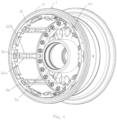
- Figure 1 shows a section of a typical wheel assembly comprising a wheel rim or tube well 1 having an outer diameter surface 10, on which a tyre (not shown) will usually be mounted, and an inner diameter surface 20 defining an interior cavity in which a brake assembly (such as shown in Fig. 2 ) will typically be arranged around a wheel hub 30.
- the hub 30 would be attached by bearing to an axle (not shown).
- the hub 30 is connected to the wheel rim 1 via a web 40.
- Rotor disc torque bars 50 extend axially across the tube well 1 for engagement with the brake discs.
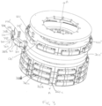
- a typical brake assembly is shown in Fig. 2 and comprises a stack of alternating rotor disks 100 and stator disks 200 arranged along an axis A and rotationally coupled to the wheel.
- Figure 2 shows four rotor disks and five stator disks but any suitable number of disks may be provided.
- the brake rotor disks 100 are rotationally coupled to the wheel rim 1 via the torque bars 50 such that the rotor disks rotate with the wheel but can move axially relative thereto.
- the brake rotor disks are provided with rotor lugs 110 spaced around the outer periphery of the disk with gaps or slots 20 defined between adjacent lugs 110 to engage with the torque bars 50 of the wheel.
- stator disks 200 are arranged between each adjacent pair of rotor disks and at either end of the brake stack. The stator disks are coupled to the wheel axle so that they do not rotate relative to the axle or to the rotor disks but can move axially relative thereto. To brake the wheel, pressure is applied to an end of the brake stack to push the disks together into frictional engagement which prevents the rotor disks from rotating relative to the axle and stator disks and thereby prevents rotation of the wheel. The friction generates heat.
- a heat shield is typically mounted to the inner diameter surface 20 of the wheel.
- the heat shield may be a single tubular shield or, as shown in the example of Fig. 1 , may be formed of several heat shield panels 60 provided between the rotor drive lugs 50.
- the heat shield/panels 60 is in the form of several thin metal sheets or layers sandwiched together, including an inner layer and an outer layer, and possible one or more intermediate layers, and with insulation gaps therebetween and is attached to the wheel so as to be spaced apart from the wheel inner diameter surface 20 by a small insulation gap (not shown).
- the term ⁇ inner layer' is used for the layer of the heat shield panel closest to the tube well and 'outer layer' is the layer of the heat shield panel furthest from the tube well.
- the adjoining edges 60a, 60b of the panels are connected by means of connectors 70.
- the connectors 70 each define a seam between adjacent panels.
- the heat shield materials also experience high temperatures.
- the temperature at the inner surface of the heat shield is higher than that at the outer surface which means that the inner layer of the panels will become hotter than the outer layer. Consequently, the inner layer will undergo greater thermal expansion than the outer layer. This can cause the heat shield to be damaged and/or to contact the wall of the tube well 1 by being deflected into the insulation gap between the heat shield and the tube well interior surface.
- the retainer is made of relatively thin, light material, deformation of the panels can cause the retainer to deflect outwards and contact the wheel rim and this can result in damage and wheel abrasion. Also, if the retainers are not sufficiently strong to retain the heat shield panels in such conditions, the heat shield panels themselves can also contact the wheel. This can cause wheel abrasion and/or heat shield damage/abrasion and require the entire wheel assembly to be replaced.
- the aim of the present disclosure is to provide a simple, lightweight heat shield assembly that avoids some of these problems but still provides the wheel with protection against heat generated by the brake assembly. This is achieved by providing heat shields on the rotor lugs of the rotor disks of the brake assembly as described further below, rather than attached to the wheel or in the space between the wheel and the brake stack.
- the heat shield assembly according to the disclosure rotates with the rotors and removes the risk of contact with the wheel whilst still having good thermal properties and being small, simple and lightweight.
- the heat shield assembly comprises a heat shield component 300 having a substantially C-shaped body of heat shield material defining a hollow substantially rectangular form having a top 310 and opposing side walls 320, 330 extending from the top to bottom side wall edges 340, the top and the side walls defining an interior cavity 350 shaped and sized to fit over a rotor disk lug 110', the heat shield component further having flanges 360a, 360b, 360c, 360d extending outwardly from the bottom side wall edges in the axial and radial directions - i.e. extending out from the bottom of the rectangle on all sides.
- the heat shield component comprises two segments 301, 302 that combine to form the rectangular form and wherein the two segments overlap in a region 312 where they join. This simplifies assembly of the heat shield component onto the rotor lug as one segment can bit fitted over each end of the lug.
- the heat shield component could, however, be provided by a single-piece component of flexible material that can be stretched or otherwise fitted over the lug.
- the heat shield component 300 is secured to the lug by e.g. rivets 160 or other fasteners. Where the rotor lug is provided with clips 150', the heat shield component is fitted over the clips. The heat shield component and the clips could be secured to the lug by the same rivets/fasteners 160 or by different fasteners.
- the heat shield component may be open at each end between the side walls, allowing the caps150' which are located over the ends of the lugs between the lug and the heat shield component, to extend from the open ends to provide the additional reinforcement to the lugs as mentioned above. In other words, the heat shield components wrap around the non-loaded surfaces of the lugs and clips leaving the loaded surfaces of the clips free.
- a heat shield component 300 is provided over each lug 110' 100' of a rotor disk and the flanges 360a-d are sized such that, in the circumferential direction, the flange 360c, 360d of a heat shield component on one lug extends to abut or slightly overlap the flange of a heat shield component 360c, 360d on the adjacent lug when the disk and lugs are in the unworn state.
- the flanges cover the lug surfaces, the slots or gaps 120' between the lugs and the spaces between the rotor disks 100' and stator disks 200' in the axial direction A.
- the flanges are formed such that as the disks/lugs become worn in the circumferential dimension, the flange of one heat shield component will overlap/further overlap that of the adjacent component.
- the flanges 360a, 360b in the axial direction also extend such that flanges of heat shield components on lugs of axially adjacent rotor disks abut or slightly overlap each other in the axial direction and thus also cover the periphery of the intermediate stator disk.
- the flanges are configured such that as the disks wear and become thinner (axially), the flanges will overlap/ further overlap to avoid buckling, deformation or damage to the heat shield and to maintain full coverage of the brake stack as the brake components wear. This can best be seen by comparing Figs.
- the flanges may be formed as shown in e.g. Figs. 5A and 5B wherein the flange 360b on one side of the component is raised relative to the flange 360a on the other side and adjacent heat shield components are assembled such that the lower flange of one component is adjacent the raised flange of the next component. During wear, the lower flange of the one component can then move underneath the raised flange of the adjacent component as seen in Fig. 5B .
- the flanges may be formed of a flexible material that lifts as an adjacent flange moves underneath it.
- Various types of heat shield material are known and any available heat shield material could be used for the heat shield components of this disclosure.
- the heat shield components shown in the examples have a single layer of heat shield material. They could, however, be formed of multiple layers to provide a greater heat barrier.
- the heat shield components are configured to provide full coverage across the brake stack, they will also act to catch any brake dust that is generated, in addition to providing the wheel with protection against the heat generated by the brake stack.
- the heat shields on the rotor lugs in this way, and providing for overlap as the brake components wear, the risk of the heat shield contacting the wheel due to thermal expansion, and, thus, the risk of abrasion is considerably reduced.
- the arrangement of this disclosure also protects the torque bars from direct radiation heat from the brake stack.
Landscapes
- Engineering & Computer Science (AREA)
- General Engineering & Computer Science (AREA)
- Mechanical Engineering (AREA)
- Transportation (AREA)
- Braking Arrangements (AREA)
Priority Applications (2)
| Application Number | Priority Date | Filing Date | Title |
|---|---|---|---|
| EP23461503.7A EP4403790A1 (de) | 2023-01-18 | 2023-01-18 | Hitzeschildanordnung |
| US18/411,386 US20240240684A1 (en) | 2023-01-18 | 2024-01-12 | Heat shield assembly |
Applications Claiming Priority (1)
| Application Number | Priority Date | Filing Date | Title |
|---|---|---|---|
| EP23461503.7A EP4403790A1 (de) | 2023-01-18 | 2023-01-18 | Hitzeschildanordnung |
Publications (1)
| Publication Number | Publication Date |
|---|---|
| EP4403790A1 true EP4403790A1 (de) | 2024-07-24 |
Family
ID=85018040
Family Applications (1)
| Application Number | Title | Priority Date | Filing Date |
|---|---|---|---|
| EP23461503.7A Pending EP4403790A1 (de) | 2023-01-18 | 2023-01-18 | Hitzeschildanordnung |
Country Status (2)
| Country | Link |
|---|---|
| US (1) | US20240240684A1 (de) |
| EP (1) | EP4403790A1 (de) |
Citations (3)
| Publication number | Priority date | Publication date | Assignee | Title |
|---|---|---|---|---|
| US3958833A (en) * | 1974-10-29 | 1976-05-25 | The Bendix Corporation | Heat shield and drive key apparatus for disc brake |
| WO2005106279A1 (en) * | 2004-04-15 | 2005-11-10 | Goodrich Corporation | Method and apparatus for protecting a friction brake disc |
| EP3753793A1 (de) * | 2019-06-21 | 2020-12-23 | Goodrich Corporation | Bremssystem für ein flugzeugrad |
-
2023
- 2023-01-18 EP EP23461503.7A patent/EP4403790A1/de active Pending
-
2024
- 2024-01-12 US US18/411,386 patent/US20240240684A1/en active Pending
Patent Citations (3)
| Publication number | Priority date | Publication date | Assignee | Title |
|---|---|---|---|---|
| US3958833A (en) * | 1974-10-29 | 1976-05-25 | The Bendix Corporation | Heat shield and drive key apparatus for disc brake |
| WO2005106279A1 (en) * | 2004-04-15 | 2005-11-10 | Goodrich Corporation | Method and apparatus for protecting a friction brake disc |
| EP3753793A1 (de) * | 2019-06-21 | 2020-12-23 | Goodrich Corporation | Bremssystem für ein flugzeugrad |
Also Published As
| Publication number | Publication date |
|---|---|
| US20240240684A1 (en) | 2024-07-18 |
Similar Documents
| Publication | Publication Date | Title |
|---|---|---|
| US5248013A (en) | Heatshield installation for aircraft brake | |
| US9541145B2 (en) | Keyed brake disk assembly | |
| EP2878846B1 (de) | Verkeilte Bremsscheibenanordnung | |
| US5085295A (en) | Brake rotor and stator discs with multiple rings joined by pins | |
| GB2174774A (en) | A disc brake for a vehicle wheel | |
| EP4403790A1 (de) | Hitzeschildanordnung | |
| EP3051166B1 (de) | Reibscheiben mit schwimmenden verschleissauskleidungen | |
| EP3418601B1 (de) | Lamellenbremsanordnung mit hubbegrenzungsstift | |
| US20240270374A1 (en) | Heat shield assembly | |
| US20230398818A1 (en) | Heat shield panel retainer | |
| EP3404283B1 (de) | Torsionsrohr | |
| EP4321769B1 (de) | Hitzeschildtafel | |
| EP4155570B1 (de) | Rotorclip für bremsenanordnung | |
| US12454228B2 (en) | Heat shield assembly for wheel | |
| US12486028B2 (en) | Heat shield panel connector | |
| US12459312B2 (en) | Heat shield panel retainer | |
| US12545399B2 (en) | Heat shield panel retainer | |
| US4131321A (en) | Torque lug drive | |
| EP4155571B1 (de) | Befestigungsklammer für ein hitzeschildpaneel | |
| US12486877B2 (en) | Rotor clip for brake assembly |
Legal Events
| Date | Code | Title | Description |
|---|---|---|---|
| PUAI | Public reference made under article 153(3) epc to a published international application that has entered the european phase |
Free format text: ORIGINAL CODE: 0009012 |
|
| STAA | Information on the status of an ep patent application or granted ep patent |
Free format text: STATUS: THE APPLICATION HAS BEEN PUBLISHED |
|
| AK | Designated contracting states |
Kind code of ref document: A1 Designated state(s): AL AT BE BG CH CY CZ DE DK EE ES FI FR GB GR HR HU IE IS IT LI LT LU LV MC ME MK MT NL NO PL PT RO RS SE SI SK SM TR |
|
| STAA | Information on the status of an ep patent application or granted ep patent |
Free format text: STATUS: REQUEST FOR EXAMINATION WAS MADE |
|
| 17P | Request for examination filed |
Effective date: 20250122 |
|
| GRAP | Despatch of communication of intention to grant a patent |
Free format text: ORIGINAL CODE: EPIDOSNIGR1 |
|
| STAA | Information on the status of an ep patent application or granted ep patent |
Free format text: STATUS: GRANT OF PATENT IS INTENDED |
|
| INTG | Intention to grant announced |
Effective date: 20250604 |
|
| GRAJ | Information related to disapproval of communication of intention to grant by the applicant or resumption of examination proceedings by the epo deleted |
Free format text: ORIGINAL CODE: EPIDOSDIGR1 |
|
| STAA | Information on the status of an ep patent application or granted ep patent |
Free format text: STATUS: REQUEST FOR EXAMINATION WAS MADE |
|
| GRAP | Despatch of communication of intention to grant a patent |
Free format text: ORIGINAL CODE: EPIDOSNIGR1 |
|
| STAA | Information on the status of an ep patent application or granted ep patent |
Free format text: STATUS: GRANT OF PATENT IS INTENDED |
|
| INTC | Intention to grant announced (deleted) | ||
| INTG | Intention to grant announced |
Effective date: 20251103 |
|
| GRAS | Grant fee paid |
Free format text: ORIGINAL CODE: EPIDOSNIGR3 |