EP4288634B1 - Gepulster hochleistungsbohrmeissel und bohrwerkzeug - Google Patents
Gepulster hochleistungsbohrmeissel und bohrwerkzeug Download PDFInfo
- Publication number
- EP4288634B1 EP4288634B1 EP22702475.9A EP22702475A EP4288634B1 EP 4288634 B1 EP4288634 B1 EP 4288634B1 EP 22702475 A EP22702475 A EP 22702475A EP 4288634 B1 EP4288634 B1 EP 4288634B1
- Authority
- EP
- European Patent Office
- Prior art keywords
- drilling
- bit
- face
- turbine
- drill bit
- Prior art date
- Legal status (The legal status is an assumption and is not a legal conclusion. Google has not performed a legal analysis and makes no representation as to the accuracy of the status listed.)
- Active
Links
Images

Classifications
-
- E—FIXED CONSTRUCTIONS
- E21—EARTH OR ROCK DRILLING; MINING
- E21B—EARTH OR ROCK DRILLING; OBTAINING OIL, GAS, WATER, SOLUBLE OR MELTABLE MATERIALS OR A SLURRY OF MINERALS FROM WELLS
- E21B7/00—Special methods or apparatus for drilling
- E21B7/14—Drilling by use of heat, e.g. flame drilling
- E21B7/15—Drilling by use of heat, e.g. flame drilling of electrically generated heat
-
- E—FIXED CONSTRUCTIONS
- E21—EARTH OR ROCK DRILLING; MINING
- E21B—EARTH OR ROCK DRILLING; OBTAINING OIL, GAS, WATER, SOLUBLE OR MELTABLE MATERIALS OR A SLURRY OF MINERALS FROM WELLS
- E21B10/00—Drill bits
-
- E—FIXED CONSTRUCTIONS
- E21—EARTH OR ROCK DRILLING; MINING
- E21B—EARTH OR ROCK DRILLING; OBTAINING OIL, GAS, WATER, SOLUBLE OR MELTABLE MATERIALS OR A SLURRY OF MINERALS FROM WELLS
- E21B10/00—Drill bits
- E21B10/42—Rotary drag type drill bits with teeth, blades or like cutting elements, e.g. fork-type bits, fish tail bits
- E21B10/43—Rotary drag type drill bits with teeth, blades or like cutting elements, e.g. fork-type bits, fish tail bits characterised by the arrangement of teeth or other cutting elements
-
- E—FIXED CONSTRUCTIONS
- E21—EARTH OR ROCK DRILLING; MINING
- E21B—EARTH OR ROCK DRILLING; OBTAINING OIL, GAS, WATER, SOLUBLE OR MELTABLE MATERIALS OR A SLURRY OF MINERALS FROM WELLS
- E21B10/00—Drill bits
- E21B10/46—Drill bits characterised by wear resisting parts, e.g. diamond inserts
- E21B10/56—Button-type inserts
- E21B10/567—Button-type inserts with preformed cutting elements mounted on a distinct support, e.g. polycrystalline inserts
-
- E—FIXED CONSTRUCTIONS
- E21—EARTH OR ROCK DRILLING; MINING
- E21C—MINING OR QUARRYING
- E21C37/00—Other methods or devices for dislodging with or without loading
- E21C37/18—Other methods or devices for dislodging with or without loading by electricity
Definitions
- the present invention relates to the field of drilling and more particularly concerns a high-power pulsed rotary drilling tool.
- Another known solution is to use a high-power pulsed tool that triggers electric arcs in the rock from a high-voltage electrode and a ground electrode subjected to a high potential difference, for example of the order of a few tens of kilovolts to a few hundred kilovolts.
- this solution only breaks the rock at the level of the pair of electrodes, which can make the process relatively time-consuming.
- the document CN 109577864A relates to a drill bit for a drilling tool.
- the drill bit comprises a drill bit body having a drilling face and a face for attaching the drill bit to a rotor assembly of the drilling tool.
- the central channel and fluid circulation holes are used for circulating drilling fluid between the attachment face and the drilling face, opening at a circular central face opening of the drilling face.
- the drill bit comprises a single high-voltage electrode, disposed in the channel passing centrally through the central face opening, and a single ground electrode disposed around the central face opening.
- the drilling face comprises a plurality of drilling teeth which appear uniformly distributed on an external surface.
- the document US 8172006 B2 relates to a drilling tool whose bit comprises electro-grinding electrodes.
- the bit comprises both teeth and a high-voltage electrode surrounded by an annular ground electrode.
- the electrical pulses are therefore concentrated only at the center of the tool head, which can limit its effectiveness and therefore presents a disadvantage.
- the electrodes can be damaged because they are directly exposed to the rock when the bit rotates.
- the bit comprises rows of teeth, a high-voltage electrode and an offset electrode arranged in place of a row of teeth.
- the electrical pulses are concentrated only on one side of the tool, which can limit its effectiveness and therefore presents a disadvantage.
- the electrodes may be damaged because they are directly exposed to the rock as the drill bit rotates. In the embodiments of FIGS.
- the tool is toothless and is not rotatable so as not to damage the electrodes.
- High-voltage electrodes are distributed in the center of the front face of the drill bit and ground electrodes are distributed around the high-voltage electrodes, on the periphery of the front face of the drill bit.
- This configuration has the disadvantage of requiring a lot of energy to generate pulses between each of the high-voltage electrodes and a ground electrode.
- drilling can be time-consuming with such a tool since it is only electrical and not mechanically rotating.
- the invention firstly relates to a drill bit for a drilling tool, said drill bit comprising a drill bit body having a drilling face and a face for fixing the drill bit to a rotor assembly of the drilling tool, said drill bit body defining a through channel for the passage of the fluid flow connecting the fixing face to the drilling face by opening at a circular central facial opening of the drilling face, the drilling face comprising an external surface connecting the central facial opening to the fixing face and from which extends a plurality of drilling members distributed uniformly on said external surface, each drilling member comprising a fin, extending radially from the external surface from the fixing face into the central facial opening, and a plurality of drilling teeth extending from said fin while being arranged side-by-side between a first drilling tooth located at the end of the face of drilling and a last drilling tooth located on the side of the fixing face, and each comprising a base and a cutting element arranged at the end of said base, the drill bit comprising a high-voltage electrode arranged in the through channel, at the
- Each pair of electrodes formed by the high-voltage electrode and a ground electrode is configured to trigger an electric arc when said pair receives a voltage delivered to its terminals by the high-power pulse generator.
- the through channel makes it possible to route the flow of fluid through the bit so that the fluid circulates continuously around the high-voltage electrode, thus forming a fluid screen having a dielectric element function allowing the electric arc to form between the high-voltage electrode and one of the ground electrodes.
- the ground electrodes have a tangential speed greater than the tangential speed of the high-voltage electrode, which is close to zero since the high-voltage electrode is located at the center of the front face of the bit body.
- a voltage is applied between the high-voltage electrode and the ground electrodes, an electric arc is generated between the high-voltage electrode and one of the ground electrodes and through the rock while the bit is rotating.
- Such an arrangement and operation allow the rotating bit to be as close as possible to the zone weakened by electrical fragmentation while protecting the high-voltage electrode and the ground electrodes from direct friction on the rock.
- the fluid circulating between the high-voltage electrode and the ground electrodes has a dual function: a dielectric element function because, between the fluid and the rock, the electric arc will favor the passage in the rock and thus fracture it and a drilling mud function because the circulation of the fluid allows the rock debris to be evacuated, by conveying it to the surface.
- the fluid flow allows the inter-electrode area to be cleaned.
- the drilling members are uniformly distributed on the external surface around the bit body in order to improve the efficiency of drilling, in particular mechanical, while allowing the flow of drilling mud between the drilling members.
- the drill body comprises at least three drilling members, preferably four, five or six drilling members to improve drilling efficiency while allowing the flow of drilling mud between the drilling members.
- the fins are made from material from the external surface of the drill bit body in order to improve the solidity of the drill bit and therefore the efficiency of drilling.
- the tooth bases of a drilling member are made from the material of the fin of said drilling member in order to improve the solidity of the drill bit and therefore the efficiency of the drilling.
- the fins extend on the outer surface in a curved manner in the direction opposite to the rotation of the drill bit for the purpose of drilling efficiency.
- each drilling member comprises at least three drilling teeth, preferably four, five or six drilling teeth in order to improve drilling efficiency.
- the base is of substantially cylindrical shape extending in a direction orthogonal to the axis of rotation of the drill bit in order to make the teeth solid and thus improve the efficiency of drilling and the duration of tool life.
- the cutting elements are made of a hard and abrasive drilling material, for example from polycrystalline diamond particles bonded together, in particular of the “polycrystalline diamond compact” (PDC) type.
- PDC polycrystalline diamond compact
- the ground electrodes being identical, the high-voltage electrode and the ground electrodes each have at least part of a spherical shape in order to slow down the erosion of the electrodes.
- the electrodes could have a pointed shape, for example conical, or any other suitable shape.
- the electrodes each having at least a partial spherical shape the diameter of the high-voltage electrode is at least twice the diameter of each ground electrode in order to allow the formation of an electric arc between the high-voltage electrode and any of the ground electrodes.
- the high-voltage electrode and the six ground electrodes are made of an electrically conductive material, for example metal such as, preferably, steel.
- the invention also relates to a high-power pulsed rotary drilling tool, said drilling tool comprising a stator assembly and a rotor assembly, said stator assembly comprising a hollow cylindrical body having an attachment end adapted to be connected to a drill rod and a free end, said rotor assembly comprising a turbine, mounted inside the body at the attachment end and configured to be driven by a flow of fluid provided by the drill rod in order to drive said rotor assembly in rotation, a high-power pulse generator mounted inside the body and securely connected to the turbine and a drill bit as previously presented extending outside the cylindrical body at the free end of the stator assembly.
- the drilling tool further includes an electrical generator configured to convert mechanical energy from the rotating turbine into electrical energy to power the high-power pulse generator.
- the generator is mounted inside the stator assembly.
- the drilling tool further comprises a drilling motor mounted inside the body, securely connected to the high-power pulse generator and configured to be driven by the flow of fluid having passed through the turbine.
- the drilling tool further comprises a steering device securely connected to the drill bit and in the form of an articulated tube configured to receive the power supplied by the turbine or the increased power supplied by the drilling motor and to transmit said power to the drill bit, to steer the drill bit in a given direction and to transfer the fluid flow from the turbine to the drill bit.
- a steering device securely connected to the drill bit and in the form of an articulated tube configured to receive the power supplied by the turbine or the increased power supplied by the drilling motor and to transmit said power to the drill bit, to steer the drill bit in a given direction and to transfer the fluid flow from the turbine to the drill bit.
- the figures show an example of a drilling tool 1 according to the invention.
- the drilling tool 1 is rotary and has high pulsed powers.
- the drilling tool 1 comprises a stator assembly 10 and a rotor assembly 20.
- the stator assembly 10 comprises a hollow cylindrical body 110 having a fixing end 110A, adapted to be connected to a drill rod 2, and a free end 110B.
- the rotor assembly 20 includes a turbine 210, a high-power pulse generator 220, and a drill bit 230.
- the drilling tool 1 further includes an electricity generator 240, a drilling motor 250, and a steering device 260.
- the turbine 210 is mounted inside the body 110 of the stator assembly 10 at the attachment end 110A and is configured to be driven by a fluid flow provided by the drill rod 2 to drive said rotor assembly 20 into rotation.
- the electricity generator 240 is configured to convert mechanical energy from the rotating turbine 210 into electrical energy.
- the high-power pulse generator 220 is mounted inside the body 110 of the stator assembly 10 and is securely connected to the turbine 210.
- the drilling motor 250 is of the “mud motor” type.
- the drilling motor 250 is mounted inside the body 110 of the stator assembly 10 while being integrally connected to the high-power pulse generator 220 and is configured to be driven by the flow of fluid having passed through the turbine 210 in order to increase the torque generated by the turbine 210 and provide it to the drill bit 230 via the steering device 260.
- the steering device 260 is securely connected on the one hand to the drilling motor 250 and on the other hand to the drill bit 230.
- the steering device 260 is in the form of an articulated tube configured both to receive the increased power provided by the drilling motor 250 and transmit said increased power to the drill bit 230, to steer the drill bit 230 in a given direction, and to transfer the flow of fluid from the turbine 210 via the drilling motor 250 to the drill bit 230.
- the drill bit 230 is connected to the steering device 260 via a tubular connection portion 270 so as to extend outside the hollow cylindrical body 110 of the stator assembly 10 by the free end 110B.
- the drill bit 230 is rotatable about an axis of rotation X.
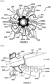
- the drill bit 230 comprises a drill bit body 231 having a drilling face 231A and a fixing face 231B ([ Fig.2 ]).
- the drilling face 231A is intended to come into contact with the rock in order to crush it.
- the fixing face 231B is configured to fix the drill bit 230 to the tubular connection portion 270 such that the drill bit body 231 and the tubular connection portion 270 are coaxially connected.
- the drill body 231 delimits a through channel 231C for the passage of the fluid flow connecting the fixing face 231B, at the connection to the tubular connection portion 270, to the drilling face 231A, opening out at a central circular facial opening 231A1 of the drilling face 231A ([ Fig.3 ]) to allow the flow of fluid to circulate from the drill bit 230 towards the rock in order in particular to evacuate rock debris.
- the drill bit 230 comprises a high-voltage electrode 232C arranged at the center of the central facial opening 231A1 and having a half-sphere shape whose axis coincides with the axis of rotation X.
- the axis of rotation X passes through the center of the central facial opening 231A1 and the center of the high-voltage electrode 232C.
- the drill body 231 includes an outer surface 232 extending from the central face opening 231A1 to the attachment face 231B and from which extends a plurality of drilling (or cutting) members 233 adapted to break rock.
- the drilling members 233 are preferably made from material of the bit body 231 and are uniformly distributed on the external surface 232, around the bit body 231.
- the bit 230 comprises six drilling members 233.
- Each drilling member 233 includes a fin 233A formed from material of the outer surface 232 extending radially in a curved manner in the direction opposite to the rotation of the drilling bit 230 for the purpose of drilling efficiency.
- Each fin 233A includes a distal end extending partially into the central facial opening 231A1 and a proximal end located at the junction between the outer surface 232 and the attachment face 231B ([ Fig.2 ]). Each pair of adjacent fins 233A delimits a groove 234 allowing in particular the evacuation of drilling mud.
- Drill teeth 233B are formed from the material of the fin 233A by being distributed side by side along the fin 233A from the distal end toward the proximal end.
- each drilling member 230 comprises five drilling teeth 233B.
- each drilling tooth 233B extends from the fin 233A in a direction orthogonal to the rotation axis X of the drill bit 230 so as to excavate the rock efficiently.
- the assembly comprising each first drilling tooth of each drilling member 233 constitutes the end of the drill body 231 first coming into contact with the rock.
- the high-voltage electrode 232C is arranged set back from the first drilling teeth 233B of each drilling member 233, that is to say set back in the through-channel 231C for the passage of fluid, in order to protect it from friction of the rock during rotation of the drill bit 230.
- each drilling tooth 233B comprises a base 233B1 and a cutting element 233B2.
- the base 233B1 is made from the material of the fin 233A and is of substantially cylindrical shape extending in a direction orthogonal to the axis of rotation X of the drill bit 230.
- the cutting element 233B2 is arranged at the end of the base 233B1 in the direction of rotation of the drill bit 230 in order to drill the rock by rotation of the rotor assembly 20.
- the cutting element 233B2 is made of a hard and abrasive drilling material, for example from polycrystalline diamond particles bonded together, in particular of the “polycrystalline diamond compact” (PDC) type.
- the cutting elements 233B2 may be manufactured separately from the bit body 231 and then secured to the bases 233B1 using a bonding material such as a brazing alloy.
- Each drilling member 233 comprises a ground electrode 233C placed at the end of the fin 233A, at the level of the high-voltage electrode 232C, so as to extend at least partly in line with the central facial opening 231A1.
- each ground electrode 233C is arranged set back from the first drilling teeth 233B of the drilling members 233, that is to say set back in the through channel 231C for the passage of fluid, in order to protect it from friction of the rock during the rotation of the drill bit 230.
- each ground electrode 233C has a half-sphere shape whose axis can be slightly inclined in the direction of the high-voltage electrode 232C, for example between 0 and 30°, in order to improve the formation of an electric arc between the high-voltage electrode 232C and said ground electrode 233C.
- the high-voltage electrode 232C and the ground electrodes 233C are made of an electrically conductive material, for example metal such as, preferably, steel.
- Each pair of electrodes formed by the high-voltage electrode 232C and a ground electrode 233C is configured to trigger an electric arc when said pair receives a voltage delivered to its terminals by the high-power pulse generator 220.
- the fixed-cut drill bit 230 may be placed in a borehole such that the cutting elements 233B2 abut the rock formation to be drilled, with the high-voltage electrode 232C and ground electrodes 233C being shielded from the rock by the drill teeth 233B.
- a fluid for example of the mud type, is sent by the drill rod 2 into the turbine 210 in order to drive it in rotation.
- the power generator 240 driven by the turbine 210, then generates a charging current enabling the capacitors of the high-frequency pulse generator 220 to be recharged by means of a suitable electronic circuit.
- the fluid flow passes through the drilling motor 250 which increases the power (torque) transmitted to the drill bit 230 in order to drill the rock by rotation.
- the high-frequency pulse generator 220 periodically applies, for example between 0.5 and 50 pulses per second, preferably 30 pulses per second, a voltage between the high-voltage electrode 232C and the ground electrodes 233C to trigger the formation of an electric arc to generate rock fragments, which eliminates the significant mechanical stresses on the drill bit that would have had to be applied to generate these fragments.
- the through channel 231C allows the flow of fluid to be conveyed through the bit body 231 so that the fluid circulates continuously around the high-voltage electrode 232C, thereby forming a fluid shield having a dielectric function allowing the electric arc to form between the high-voltage electrode 232C and one of the ground electrodes 233C.
- the flow of fluid conveyed through the bit 230 also allows the evacuation of rock debris at the drilling zone towards the top of the wellbore.
- the ground electrodes 233C have a tangential velocity greater than the tangential velocity of the high-voltage electrode 232C, which is close to zero since the high-voltage electrode 232C is located at the center of the drilling face 231A of the drill bit body 231.
- the fluid flow surrounding the high-voltage electrode 232C creates an effective medium that provides for the formation of an electric arc in the rock between the high-voltage electrode 232C and one of the ground electrodes 233C while the drill bit 230 is rotating.
- the fluid thus has a dual function: a dielectric function because, between the fluid and the rock, the electric arc will favor the passage in the rock and thus fracture it and a drilling mud function because the circulation of the fluid allows the rock debris to be evacuated, by conveying it to the surface.
- the fluid flow allows the inter-electrode zone to be cleaned.
Landscapes
- Engineering & Computer Science (AREA)
- Mining & Mineral Resources (AREA)
- Geology (AREA)
- Life Sciences & Earth Sciences (AREA)
- Geochemistry & Mineralogy (AREA)
- General Life Sciences & Earth Sciences (AREA)
- Environmental & Geological Engineering (AREA)
- Fluid Mechanics (AREA)
- Physics & Mathematics (AREA)
- Mechanical Engineering (AREA)
- Chemical & Material Sciences (AREA)
- Crystallography & Structural Chemistry (AREA)
- Earth Drilling (AREA)
Claims (15)
- Bohrmeißel (230) für ein Bohrwerkzeug (1), wobei der Bohrmeißel (230) einen Bohrmeißelkörper (231) umfasst, der eine Bohrseite (231A) und eine Befestigungsseite (231B) des Bohrmeißels (230) an einer Rotoranordnung (20) des Bohrwerkzeugs (1) aufweist, wobei der Bohrmeißelkörper (231) einen Durchgangskanal (231C) für den Fluidstrom begrenzt, der die Befestigungsseite (231B) mit der Bohrseite (231A) verbindet, indem er im Bereich einer kreisförmigen zentralen Frontöffnung (231A1) der Bohrseite (231A) ausmündet, wobei die Bohrseite (231A) eine Außenfläche (232) umfasst, die die zentrale Frontöffnung (231A1) mit der Befestigungsseite (231B) verbindet und von der sich eine Vielzahl von Bohrorganen (233) erstreckt, die gleichmäßig auf der Außenfläche (232) verteilt sind, wobei jedes Bohrorgan (233) einen Flügel (233A) umfasst, der sich radial ab der Außenfläche (232) ab der Befestigungsseite (231B) bis in die zentrale Frontöffnung (231A1) erstreckt, und eine Vielzahl von Bohrzähnen (233B), die sich ab dem Flügel (233A) erstrecken, indem sie Seite an Seite zwischen einem ersten Bohrzahn (233), der sich im Bereich des Endes der Bohrseite (231A) befindet, und einem letzten Bohrzahn (233B), der sich auf der Seite der Befestigungsseite (231B) befindet, angeordnet sind, und jeweils eine Grundplatte (233B1) und ein Schneidelement (233B2) aufweisen, das am Ende der Grundplatte (233B1) angeordnet ist, wobei der Bohrmeißel (230) eine Hochspannungselektrode (232C) umfasst, die in dem Durchgangskanal (231C) angeordnet ist, in der Mitte der zentralen Frontöffnung (231A1) zurückgesetzt vom ersten Bohrzahn (233B) jedes Bohrorgans (233), wobei jedes Bohrorgan (233) eine Masseelektrode (233C) umfasst, die am Ende des Flügels (233A) im Bereich der Hochspannungselektrode (232C) angeordnet ist, so dass sie sich zumindest teilweise an der zentralen Frontöffnung (231A1) zurückgesetzt vom ersten Bohrzahn (233B) des Bohrorgans (233) erstreckt.
- Bohrmeißel (230) nach Anspruch 1, wobei die Bohrorgane (233) gleichmäßig auf der Außenfläche (232) um den Bohrmeißelkörper (231) herum verteilt sind.
- Bohrmeißel (230) nach einem der vorhergehenden Ansprüche, wobei der Bohrmeißelkörper (231) mindestens drei Bohrorgane (233), vorzugsweise vier, fünf oder sechs Bohrorgane (233), umfasst.
- Bohrmeißel (230) nach einem der vorhergehenden Ansprüche, wobei die Flügel (233A) aus Material der Außenfläche des Bohrmeißelkörpers (231) hervorgegangen sind.
- Bohrmeißel (230) nach einem der vorhergehenden Ansprüche, wobei die Grundplatten (233B1) der Zähne (233B) eines Bohrorgans (233) aus dem Material des Flügels (233A) des Bohrorgans (233) hervorgegangen sind.
- Bohrmeißel (230) nach einem der vorhergehenden Ansprüche, wobei sich die Flügel (233A) auf der Außenfläche (232) gekrümmt in der entgegengesetzten Drehrichtung des Bohrmeißels (230) erstrecken.
- Bohrmeißel (230) nach einem der vorhergehenden Ansprüche, wobei jedes Bohrorgan (230) mindestens drei Bohrzähne (233B), vorzugsweise vier, fünf oder sechs Bohrzähne (233B), umfasst.
- Bohrmeißel (230) nach einem der vorhergehenden Ansprüche, wobei die Grundplatte (233B1) eine im Wesentlichen zylindrische Form aufweist, indem sie sich in einer Richtung orthogonal zur Drehachse (X) des Bohrmeißels (230) erstreckt.
- Bohrmeißel (230) nach einem der vorhergehenden Ansprüche, wobei die Schneidelemente (233B2) aus einem harten und abrasiven Bohrmaterial hergestellt sind, beispielsweise aus miteinander verbundenen polykristallinen Diamantpartikeln, insbesondere vom Typ "polykristalliner Diamantkompakt" (PDC).
- Bohrmeißel (230) nach einem der vorhergehenden Ansprüche, wobei, da die Masseelektroden (233C) identisch sind, die Hochspannungselektrode (232C) und die Masseelektroden (233C) jeweils zumindest teilweise eine Kugelform aufweisen.
- Bohrmeißel (230) nach einem der vorhergehenden Ansprüche, wobei die Elektroden (232C, 233C) jeweils zumindest teilweise eine Kugelform aufweisen, der Durchmesser der Hochspannungselektrode (232C) mindestens gleich dem Doppelten des Durchmessers jeder Masseelektrode (233C) ist, um die Bildung eines Lichtbogens zwischen der Hochspannungselektrode (232C) und einer beliebigen der Masseelektroden (233C) zu ermöglichen.
- Rotierendes Bohrwerkzeug (1) mit hohen gepulsten Leistungen, wobei das Bohrwerkzeug (1) eine Statorbaugruppe (10) und eine Rotorbaugruppe (20) aufweist, wobei die Statorbaugruppe (10) einen hohlen zylindrischen Körper (110) umfasst, der ein Befestigungsende (110A), das zur Verbindung mit einer Bohrstange (2) geeignet ist, und ein freies Ende (110B) aufweist, wobei die Rotorbaugruppe (20) eine Turbine (210) umfasst, die im Inneren des Körpers (110) im Bereich des Befestigungsendes (110A) angebracht und ausgelegt ist, um durch einen von der Bohrstange (2) gelieferten Fluidstrom angetrieben zu werden, um die Rotoranordnung (20) rotatorisch anzutreiben, einen Hochleistungsimpulsgenerator (220), der im Inneren des Körpers (110) angebracht und fest mit der Turbine (210) verbunden ist, und einen Bohrmeißel (230) nach einem der vorhergehenden Ansprüche, der sich im Bereich des freien Endes (110B) der Statorbaugruppe (10) aus dem zylindrischen Körper (110) heraus erstreckt.
- Bohrwerkzeug (1) nach vorhergehendem Anspruch, ferner umfassend einen Stromgenerator (240), der ausgelegt ist, um die mechanische Energie der rotierenden Turbine (210) in elektrische Energie umzuwandeln, um den Hochleistungsimpulsgenerator (220) zu versorgen.
- Bohrwerkzeug (1) nach einem der Ansprüche 12 oder 13, ferner umfassend einen Bohrmotor (250), der im Inneren des Körpers (110) angebracht ist, fest mit dem Hochleistungsimpulsgenerator (220) verbunden ist und ausgelegt ist, um durch den Fluidstrom, der die Turbine (210) durchquert hat, angetrieben zu werden.
- Bohrwerkzeug (1) nach einem der Ansprüche 12 bis 14, ferner umfassend eine Lenkvorrichtung (260), die fest mit dem Bohrmeißel (230) verbunden ist und in Form eines Gelenkrohrs vorliegt, das ausgelegt ist, um die von der Turbine (210) gelieferte Leistung oder die vom Bohrmotor (250) gelieferte erhöhte Leistung zu empfangen und diese Leistung an den Bohrmeißel (230) zu übertragen, um den Bohrmeißel (230) in eine bestimmte Richtung zu lenken und um den von der Turbine (210) kommenden Fluidstrom an den Bohrmeißel (230) zu übertragen.
Applications Claiming Priority (2)
| Application Number | Priority Date | Filing Date | Title |
|---|---|---|---|
| FR2101063A FR3119415B1 (fr) | 2021-02-04 | 2021-02-04 | Trépan et outil de forage de hautes puissances pulsées |
| PCT/EP2022/052229 WO2022167370A1 (fr) | 2021-02-04 | 2022-01-31 | Trépan et outil de forage de hautes puissances pulsées |
Publications (3)
| Publication Number | Publication Date |
|---|---|
| EP4288634A1 EP4288634A1 (de) | 2023-12-13 |
| EP4288634C0 EP4288634C0 (de) | 2025-03-05 |
| EP4288634B1 true EP4288634B1 (de) | 2025-03-05 |
Family
ID=74860280
Family Applications (1)
| Application Number | Title | Priority Date | Filing Date |
|---|---|---|---|
| EP22702475.9A Active EP4288634B1 (de) | 2021-02-04 | 2022-01-31 | Gepulster hochleistungsbohrmeissel und bohrwerkzeug |
Country Status (7)
| Country | Link |
|---|---|
| US (1) | US12286881B2 (de) |
| EP (1) | EP4288634B1 (de) |
| JP (1) | JP2024505409A (de) |
| CN (1) | CN117203402A (de) |
| CA (1) | CA3205050A1 (de) |
| FR (1) | FR3119415B1 (de) |
| WO (1) | WO2022167370A1 (de) |
Families Citing this family (1)
| Publication number | Priority date | Publication date | Assignee | Title |
|---|---|---|---|---|
| FR3162784A1 (fr) * | 2024-05-31 | 2025-12-05 | G-Pulse Inc. | Tête de forage à électrode intermédiaire |
Family Cites Families (15)
| Publication number | Priority date | Publication date | Assignee | Title |
|---|---|---|---|---|
| US7384009B2 (en) * | 2004-08-20 | 2008-06-10 | Tetra Corporation | Virtual electrode mineral particle disintegrator |
| US8172006B2 (en) | 2004-08-20 | 2012-05-08 | Sdg, Llc | Pulsed electric rock drilling apparatus with non-rotating bit |
| US7959094B2 (en) * | 2004-08-20 | 2011-06-14 | Tetra Corporation | Virtual electrode mineral particle disintegrator |
| JP4931667B2 (ja) * | 2007-03-29 | 2012-05-16 | 株式会社熊谷組 | 放電破砕装置、及び、この装置を用いた放電破砕方法 |
| US8727036B2 (en) * | 2007-08-15 | 2014-05-20 | Schlumberger Technology Corporation | System and method for drilling |
| US8570045B2 (en) * | 2009-09-10 | 2013-10-29 | Schlumberger Technology Corporation | Drilling system for making LWD measurements ahead of the bit |
| CN102761665B (zh) | 2012-06-29 | 2014-12-31 | 惠州Tcl移动通信有限公司 | 一种基于移动终端的来电处理方法及移动终端 |
| NO339566B1 (no) * | 2014-04-08 | 2017-01-02 | Unodrill As | Hybrid borkrone |
| US9976352B2 (en) * | 2015-08-27 | 2018-05-22 | Saudi Arabian Oil Company | Rock formation drill bit assembly with electrodes |
| JP2018053573A (ja) * | 2016-09-29 | 2018-04-05 | 国立研究開発法人海洋研究開発機構 | 地盤掘削装置 |
| CN108661554B (zh) * | 2018-05-11 | 2019-08-30 | 东北石油大学 | 基于等离子通道与机械钻具联合装置及其钻井方法 |
| CN109577864B (zh) * | 2018-07-03 | 2020-04-07 | 西南石油大学 | 一种连续管高压电脉冲-机械复合钻井用电极钻头 |
| WO2020092559A1 (en) * | 2018-10-30 | 2020-05-07 | The Texas A&M University System | Systems and methods for forming a subterranean borehole |
| WO2020098415A1 (zh) * | 2018-11-12 | 2020-05-22 | 中铁工程装备集团有限公司 | 一种基于高压脉冲放电—机械联合破岩的新型掘进机 |
| CN109547906B (zh) | 2019-01-05 | 2023-12-08 | 深圳市韶音科技有限公司 | 骨传导扬声装置 |
-
2021
- 2021-02-04 FR FR2101063A patent/FR3119415B1/fr active Active
-
2022
- 2022-01-31 CA CA3205050A patent/CA3205050A1/fr active Pending
- 2022-01-31 EP EP22702475.9A patent/EP4288634B1/de active Active
- 2022-01-31 WO PCT/EP2022/052229 patent/WO2022167370A1/fr not_active Ceased
- 2022-01-31 CN CN202280010939.9A patent/CN117203402A/zh active Pending
- 2022-01-31 JP JP2023542489A patent/JP2024505409A/ja active Pending
- 2022-01-31 US US18/273,951 patent/US12286881B2/en active Active
Also Published As
| Publication number | Publication date |
|---|---|
| FR3119415B1 (fr) | 2023-01-13 |
| FR3119415A1 (fr) | 2022-08-05 |
| EP4288634C0 (de) | 2025-03-05 |
| EP4288634A1 (de) | 2023-12-13 |
| CN117203402A (zh) | 2023-12-08 |
| CA3205050A1 (fr) | 2022-08-11 |
| WO2022167370A1 (fr) | 2022-08-11 |
| US12286881B2 (en) | 2025-04-29 |
| JP2024505409A (ja) | 2024-02-06 |
| US20240410229A1 (en) | 2024-12-12 |
Similar Documents
| Publication | Publication Date | Title |
|---|---|---|
| EP4288634B1 (de) | Gepulster hochleistungsbohrmeissel und bohrwerkzeug | |
| EP0308662B1 (de) | Zahnsteinentferner | |
| FR3039851A1 (fr) | Outil d'excavation par impulsions electriques | |
| EP1636818B1 (de) | Röntgengeneratorröhre mit einem ausrichtbaren zielträgersystem | |
| EP3047550B1 (de) | Funkenstrecke einer elektrischen lichtbogenerzeugungsvorrichtung und entsprechende elektrische lichtbogenerzeugungsvorrichtung | |
| EP2472554A1 (de) | Vorrichtung zur Erzeugung von Mikrowellen mit einer Kathode bei welcher jede Extremität mit einer Spannungsquelle verbunden ist | |
| EP0185226B1 (de) | Gasdurchflusslaser und Funktionsweise eines solchen Lasers | |
| EP3047551B1 (de) | Funkenstrecke einer elektrischen lichtbogenerzeugungsvorrichtung und entsprechende elektrische lichtbogenerzeugungsvorrichtung | |
| EP1068022A1 (de) | Sprühglocke und rotationszerstäuber mit einer solchen sprühglocke | |
| FR2947193A1 (fr) | Plaquette de coupe et outil d'usinage a avance rapide integrant cette plaquette | |
| EP0298817B1 (de) | Verfahren und Vorrichtung zur Elektronenerzeugung mittels einer Feldkopplung und des photoelektrischen Effekts | |
| WO2025248354A1 (fr) | Tête de forage à électrode intermédiaire | |
| EP0427591B1 (de) | Plasmabrenner mit nicht gekühlter Plasmagasinjektion | |
| EP3413355B1 (de) | Solarpanel, das insbesondere eine fotovoltaikstruktur und mindestens zwei fotovoltaikzellen umfasst | |
| EP0343313A1 (de) | Elektrischer Motor hoher Leistung und hoher Umdrehungsgeschwindigkeit | |
| EP3715583B1 (de) | Abreinigung einer auslassöffnung eines tunnelbohrers durch ultraschallwellen | |
| FR3067520B1 (fr) | Panneau solaire comportant une structure, au moins deux cellules photovoltaiques et une barriere | |
| FR3151440A1 (fr) | Machine électrique tournante, notamment pour une motorisation de véhicule automobile | |
| FR3152374A1 (fr) | Cage intervertébrale | |
| WO2024189067A1 (fr) | Agencement d'un arbre et d'un carter | |
| WO2013050672A1 (fr) | Moyens et procédé pour la stabilisation et le stockage d'énergie d'un système de forage dirigé | |
| EP1686842A1 (de) | Plasmabrenner | |
| WO2010115617A2 (fr) | Trepan rotatif | |
| BE524116A (de) |
Legal Events
| Date | Code | Title | Description |
|---|---|---|---|
| STAA | Information on the status of an ep patent application or granted ep patent |
Free format text: STATUS: UNKNOWN |
|
| STAA | Information on the status of an ep patent application or granted ep patent |
Free format text: STATUS: THE INTERNATIONAL PUBLICATION HAS BEEN MADE |
|
| PUAI | Public reference made under article 153(3) epc to a published international application that has entered the european phase |
Free format text: ORIGINAL CODE: 0009012 |
|
| STAA | Information on the status of an ep patent application or granted ep patent |
Free format text: STATUS: REQUEST FOR EXAMINATION WAS MADE |
|
| 17P | Request for examination filed |
Effective date: 20230718 |
|
| AK | Designated contracting states |
Kind code of ref document: A1 Designated state(s): AL AT BE BG CH CY CZ DE DK EE ES FI FR GB GR HR HU IE IS IT LI LT LU LV MC MK MT NL NO PL PT RO RS SE SI SK SM TR |
|
| DAV | Request for validation of the european patent (deleted) | ||
| DAX | Request for extension of the european patent (deleted) | ||
| GRAP | Despatch of communication of intention to grant a patent |
Free format text: ORIGINAL CODE: EPIDOSNIGR1 |
|
| STAA | Information on the status of an ep patent application or granted ep patent |
Free format text: STATUS: GRANT OF PATENT IS INTENDED |
|
| INTG | Intention to grant announced |
Effective date: 20240913 |
|
| GRAS | Grant fee paid |
Free format text: ORIGINAL CODE: EPIDOSNIGR3 |
|
| GRAA | (expected) grant |
Free format text: ORIGINAL CODE: 0009210 |
|
| STAA | Information on the status of an ep patent application or granted ep patent |
Free format text: STATUS: THE PATENT HAS BEEN GRANTED |
|
| AK | Designated contracting states |
Kind code of ref document: B1 Designated state(s): AL AT BE BG CH CY CZ DE DK EE ES FI FR GB GR HR HU IE IS IT LI LT LU LV MC MK MT NL NO PL PT RO RS SE SI SK SM TR |
|
| REG | Reference to a national code |
Ref country code: GB Ref legal event code: FG4D Free format text: NOT ENGLISH |
|
| REG | Reference to a national code |
Ref country code: CH Ref legal event code: EP |
|
| REG | Reference to a national code |
Ref country code: DE Ref legal event code: R096 Ref document number: 602022011426 Country of ref document: DE |
|
| REG | Reference to a national code |
Ref country code: IE Ref legal event code: FG4D Free format text: LANGUAGE OF EP DOCUMENT: FRENCH |
|
| U01 | Request for unitary effect filed |
Effective date: 20250401 |
|
| U07 | Unitary effect registered |
Designated state(s): AT BE BG DE DK EE FI FR IT LT LU LV MT NL PT RO SE SI Effective date: 20250507 |
|
| PG25 | Lapsed in a contracting state [announced via postgrant information from national office to epo] |
Ref country code: RS Free format text: LAPSE BECAUSE OF FAILURE TO SUBMIT A TRANSLATION OF THE DESCRIPTION OR TO PAY THE FEE WITHIN THE PRESCRIBED TIME-LIMIT Effective date: 20250605 |
|
| PG25 | Lapsed in a contracting state [announced via postgrant information from national office to epo] |
Ref country code: ES Free format text: LAPSE BECAUSE OF FAILURE TO SUBMIT A TRANSLATION OF THE DESCRIPTION OR TO PAY THE FEE WITHIN THE PRESCRIBED TIME-LIMIT Effective date: 20250305 |
|
| PG25 | Lapsed in a contracting state [announced via postgrant information from national office to epo] |
Ref country code: NO Free format text: LAPSE BECAUSE OF FAILURE TO SUBMIT A TRANSLATION OF THE DESCRIPTION OR TO PAY THE FEE WITHIN THE PRESCRIBED TIME-LIMIT Effective date: 20250605 |
|
| PG25 | Lapsed in a contracting state [announced via postgrant information from national office to epo] |
Ref country code: HR Free format text: LAPSE BECAUSE OF FAILURE TO SUBMIT A TRANSLATION OF THE DESCRIPTION OR TO PAY THE FEE WITHIN THE PRESCRIBED TIME-LIMIT Effective date: 20250305 |
|
| PG25 | Lapsed in a contracting state [announced via postgrant information from national office to epo] |
Ref country code: GR Free format text: LAPSE BECAUSE OF FAILURE TO SUBMIT A TRANSLATION OF THE DESCRIPTION OR TO PAY THE FEE WITHIN THE PRESCRIBED TIME-LIMIT Effective date: 20250606 |
|
| U1N | Appointed representative for the unitary patent procedure changed after the registration of the unitary effect |
Representative=s name: BORNIER, RAYNALD; FR |
|
| PG25 | Lapsed in a contracting state [announced via postgrant information from national office to epo] |
Ref country code: SM Free format text: LAPSE BECAUSE OF FAILURE TO SUBMIT A TRANSLATION OF THE DESCRIPTION OR TO PAY THE FEE WITHIN THE PRESCRIBED TIME-LIMIT Effective date: 20250305 |
|
| PG25 | Lapsed in a contracting state [announced via postgrant information from national office to epo] |
Ref country code: PL Free format text: LAPSE BECAUSE OF FAILURE TO SUBMIT A TRANSLATION OF THE DESCRIPTION OR TO PAY THE FEE WITHIN THE PRESCRIBED TIME-LIMIT Effective date: 20250305 |
|
| PG25 | Lapsed in a contracting state [announced via postgrant information from national office to epo] |
Ref country code: CZ Free format text: LAPSE BECAUSE OF FAILURE TO SUBMIT A TRANSLATION OF THE DESCRIPTION OR TO PAY THE FEE WITHIN THE PRESCRIBED TIME-LIMIT Effective date: 20250305 |
|
| PG25 | Lapsed in a contracting state [announced via postgrant information from national office to epo] |
Ref country code: SK Free format text: LAPSE BECAUSE OF FAILURE TO SUBMIT A TRANSLATION OF THE DESCRIPTION OR TO PAY THE FEE WITHIN THE PRESCRIBED TIME-LIMIT Effective date: 20250305 |
|
| PG25 | Lapsed in a contracting state [announced via postgrant information from national office to epo] |
Ref country code: IS Free format text: LAPSE BECAUSE OF FAILURE TO SUBMIT A TRANSLATION OF THE DESCRIPTION OR TO PAY THE FEE WITHIN THE PRESCRIBED TIME-LIMIT Effective date: 20250705 |
|
| PLBE | No opposition filed within time limit |
Free format text: ORIGINAL CODE: 0009261 |
|
| STAA | Information on the status of an ep patent application or granted ep patent |
Free format text: STATUS: NO OPPOSITION FILED WITHIN TIME LIMIT |
|
| REG | Reference to a national code |
Ref country code: CH Ref legal event code: L10 Free format text: ST27 STATUS EVENT CODE: U-0-0-L10-L00 (AS PROVIDED BY THE NATIONAL OFFICE) Effective date: 20260114 |
|
| U20 | Renewal fee for the european patent with unitary effect paid |
Year of fee payment: 5 Effective date: 20251219 |
|
| 26N | No opposition filed |
Effective date: 20251208 |