EP4288368B1 - Vorrichtung, system und verfahren zum bewegen einer last zwischen einem schwimmenden schiff und einer unterwasserposition - Google Patents
Vorrichtung, system und verfahren zum bewegen einer last zwischen einem schwimmenden schiff und einer unterwasserposition Download PDFInfo
- Publication number
- EP4288368B1 EP4288368B1 EP21711658.1A EP21711658A EP4288368B1 EP 4288368 B1 EP4288368 B1 EP 4288368B1 EP 21711658 A EP21711658 A EP 21711658A EP 4288368 B1 EP4288368 B1 EP 4288368B1
- Authority
- EP
- European Patent Office
- Prior art keywords
- connector
- chamber
- hoisting member
- length
- latch
- Prior art date
- Legal status (The legal status is an assumption and is not a legal conclusion. Google has not performed a legal analysis and makes no representation as to the accuracy of the status listed.)
- Active
Links
Images



Classifications
-
- B—PERFORMING OPERATIONS; TRANSPORTING
- B63—SHIPS OR OTHER WATERBORNE VESSELS; RELATED EQUIPMENT
- B63B—SHIPS OR OTHER WATERBORNE VESSELS; EQUIPMENT FOR SHIPPING
- B63B27/00—Arrangement of ship-based loading or unloading equipment for cargo or passengers
- B63B27/16—Arrangement of ship-based loading or unloading equipment for cargo or passengers of lifts or hoists
-
- B—PERFORMING OPERATIONS; TRANSPORTING
- B66—HOISTING; LIFTING; HAULING
- B66C—CRANES; LOAD-ENGAGING ELEMENTS OR DEVICES FOR CRANES, CAPSTANS, WINCHES, OR TACKLES
- B66C13/00—Other constructional features or details
- B66C13/02—Devices for facilitating retrieval of floating objects, e.g. for recovering crafts from water
-
- E—FIXED CONSTRUCTIONS
- E02—HYDRAULIC ENGINEERING; FOUNDATIONS; SOIL SHIFTING
- E02B—HYDRAULIC ENGINEERING
- E02B17/00—Artificial islands mounted on piles or like supports, e.g. platforms on raisable legs or offshore constructions; Construction methods therefor
- E02B17/04—Equipment specially adapted for raising, lowering, or immobilising the working platform relative to the supporting construction
- E02B17/08—Equipment specially adapted for raising, lowering, or immobilising the working platform relative to the supporting construction for raising or lowering
- E02B17/0809—Equipment specially adapted for raising, lowering, or immobilising the working platform relative to the supporting construction for raising or lowering the equipment being hydraulically actuated
-
- E—FIXED CONSTRUCTIONS
- E21—EARTH OR ROCK DRILLING; MINING
- E21B—EARTH OR ROCK DRILLING; OBTAINING OIL, GAS, WATER, SOLUBLE OR MELTABLE MATERIALS OR A SLURRY OF MINERALS FROM WELLS
- E21B19/00—Handling rods, casings, tubes or the like outside the borehole, e.g. in the derrick; Apparatus for feeding the rods or cables
- E21B19/002—Handling rods, casings, tubes or the like outside the borehole, e.g. in the derrick; Apparatus for feeding the rods or cables specially adapted for underwater drilling
Definitions
- the present invention relates to an apparatus for suspending a connector provided on a first elongated hoisting member during a subsea hoisting operation.
- the present invention also relates to a system for moving a load between a floating vessel and a submerged position.
- the present invention relates to a method for lowering a load from a floating vessel to a submerged position and a method for raising a load from a submerged position towards a floating vessel.
- fibre ropes may be preferred due to their reduced weight compared to traditional steel wire ropes. Most fibre ropes are close to neutrally buoyant in water, thereby not adding significant weight to the lifting operation.
- a challenge related with the use of fibre ropes is the excessive wear, and hence reduced lifetime, when used in repeated bending cycles under load.
- the quick deterioration is observed when the hoisting operation is performed with heave compensation, in which the same portion of the fibre rope undergoes numerous bending cycles under load during a period of time that can be prolonged for a few days.
- the lifetime of a fibre rope can also be difficult to monitor and predict in a reliable manner, leading to excessive safety factors and unnecessary frequent replacements.
- US 8 764 345 B2 discloses an apparatus according to the preamble of claim 1.
- WO 2009/005359 A1 and WO 2010/093251 A1 solve the challenge of using a fibre rope to overcome the drawbacks of a heavy steel wire rope. This is achieved by providing hoisting systems where a load being hoisted subsea is carried between two ropes in an alternated manner: a first rope will typically be a steel wire rope with a short length, such as 300 meters; and a second rope will be a fibre rope with sufficient length to reach the seabed from a floating vessel, such as up to 3000 meters or even more.
- the steel wire rope will not be extremely heavy, due to its shorter length, and will be the one undergoing bending cycles under load, thereby saving the fibre rope from the deterioration caused by this actuation.
- a disadvantage of the known solutions is that the alternation between the two wire ropes requires the use of a remotely operated vehicle (ROV) to activate the disconnection between the two wire ropes, and this makes the alternation (often referred to as "handshake") a time-consuming process that adds cost to the hoisting operation.
- ROV remotely operated vehicle
- an apparatus for suspending a connector provided on a first elongated hoisting member during a subsea hoisting operation comprises a mechanism for holding the connector, in which, when the mechanism is subjected to a hydrostatic pressure above a threshold pressure, the mechanism is changeable to a configuration for moving past the connector while the apparatus is raised.
- the hydrostatic pressure at which the apparatus is subjected to could be used for the purpose of changing the apparatus to a configuration that allows the apparatus to be raised and moved past a connector on the first elongated hoisting member.
- This is advantageous in that it removes the need to deploy a diver or an ROV in order to change the apparatus to the intended configuration.
- This is particularly advantageous in deep water operations where the operation of changing the configuration of the apparatus typically happens at depths of at least 300 meters.
- the known alternative solutions are significantly more time consuming and expensive. Also, since there is no need for ROVs or divers, the solution requires less machinery resources to be provided on the floating vessel from which the load is being suspended. Moreover, this solution requires only one operator for controlling the elongated hoisting members, whereas in the know alternative solutions there is a need for further operators, such as a diver or and ROV operator.
- the mechanism may comprise:
- the first chamber comprises a compression spring or another biasing member against which a hydraulic fluid from the second chamber is operated.
- the compression spring in the first chamber may be separated from the hydraulic fluid from the second chamber by means of a piston, a membrane, a diaphragm etc.
- a compressible fluid, a compression spring or any other biasing member will enable the mechanism to change to a configuration for moving past a connector. This is achieved by compressing the compression spring or the compressible fluid once a hydrostatic pressure is exerted above the mentioned threshold pressure.
- the apparatus may comprise a one-way valve arranged in parallel to the first control valve, the one-way valve being oriented to permit a free flow only from a hydraulic connection of the first control valve to the first chamber to another hydraulic connection of the first control valve to the second chamber.
- the apparatus may comprise a second control valve for controlling a hydraulic connection between the first control valve and the second chamber.
- the apparatus may comprise a third control valve for controlling a hydraulic connection transmitting a hydrostatic pressure into the third chamber.
- the mechanism may comprise:
- the hydraulic cylinder may be arranged so that the latch is actuatable by a piston rod connected to the piston of the hydraulic cylinder, the actuation by the piston rod causing the latch to rotate to a position for moving the mechanism past the connector while the apparatus is raised.
- the mechanism may comprise an elastic body for tensioning the rotation of the latch towards the stopper.
- the latch may comprise a density configured to position the centre of mass of the latch in relation to the pivot so that the latch automatically rotates towards the stopper.
- the apparatus may comprise a channel for passing the connector through the apparatus, wherein the mechanism is arranged in relation to the channel so that the connector is holdable within the channel.
- the contact switch may be arranged for protruding into the channel.
- a system for moving a load between a floating vessel and a submerged position comprising:
- a method for lowering a load from a floating vessel to a submerged position comprises the steps of:
- a method for raising a load from a submerged position towards a floating vessel comprises the steps of:
- the terms “lower”, “upper”, “bottom” and “top” may be used for referring to parts and portions of a component as seen when the component is in a preferred orientation of use at a submerged position.
- the terms “below”, “above”, “vertical” and “horizontal” may be used for describing a relative positioning as seen from an elevation view of a submerged position between a seabed 20 at the bottom of the view and a surface of seawater at the top of the view.
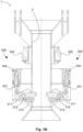
- Figures 1A and 1B show an apparatus embodiment 1 according to the present disclosure, the apparatus 1 being shown from a perspective view and from a cross-sectional view, respectively.
- the orientation of the apparatus 1 in relation to the page is in alignment with the preferred orientation of use, in which the top portion of the apparatus 1 is the closest portion to the surface of the seawater and the bottom portion of the apparatus 1 is the closest portion to the seabed 20.
- some details of the apparatus 1 have been simplified or omitted from the figures for illustrative purposes.
- the apparatus 1 in Figures 1A and 1B includes a channel 2 suitable for enclosing a portion of a first elongated hoisting member 100 while the latter is being used for suspending a load 102 from a floating vessel 10.
- the channel 2 has a tubular shape and it crosses the apparatus 1 along a vertical axis (shown in Figure 1B as a vertical dashed line). Arranging the first elongated hoisting member 100 through the channel 2 results in the apparatus 1 becoming restricted to only be able to move along the first elongated hoisting member 100.
- the apparatus embodiment 1 also includes four parts at the top that are suitable for connecting a second elongated hoisting member 200 to suspend the apparatus 1 from a floating vessel 10. Each of the four parts projects upwards and includes a transversal circular hole for fastening the connection with the second elongated hoisting member 200.
- the skilled person will be able to develop many alternative solutions for connecting the second elongated hoisting member 200 to the apparatus 1.
- the apparatus 1 may be used in a subsea hoisting operation in which a first elongated hoisting member 100, such as a fibre rope 100, is used for suspending the load 102 and a second elongated hoisting member 200, such as a steel wire rope 200, is used for suspending the apparatus 1.
- a first elongated hoisting member 100 such as a fibre rope 100
- a second elongated hoisting member 200 such as a steel wire rope 200
- the apparatus 1 includes a mechanism 300 for holding a connector 101 provided on the first elongated hoisting member 100.
- the mechanism 300 is more easily observed in Figure 1B , as most of the components of the mechanism 300 are not visible in the perspective view shown in Figure 1A .
- the mechanism 300 includes two latches 311 for holding a connector 101 within the channel 2.
- the latches 311 are rotatable around pivots 312 and the latches' rotations intersect with the interior of the channel 2 so that a connector 101 may be held within the channel 2.
- the mechanism 300 also includes a stopper 313 for each latch 311, each stopper 313 being arranged in relation to the respective latch pivot 312 so that the rotation of the respective latch 311 is stoppable at a position in which the connector 101 is holdable by the latch 311.
- the stop positions of the latches 311 can be observed as being horizontal in relation to the orientation of the page and pointing towards the interior of the channel 2.
- the latches 311 are positioned opposite to each other around the central axis of the channel 2.
- Other apparatus embodiments 1 may include a different number of latches 311.
- the skilled person may develop an apparatus embodiment 1 with a single latch 311 that is suitable for holding a connector 101 within the channel 2 without requiring any other latch 311.
- Other apparatus 1 embodiments may include three or more latches 311 positioned around the central axis of the channel 2.
- the first elongated hoisting member 100 and any connector 101 fixed to it will be passed through the channel 2.
- the latches 311 will be pushed by the connector 101 to rotate upward and away from the central axis of the channel 2.
- the connector 101 is passed through the channel 2 from the top to the bottom of the apparatus 1
- the latches 311 will be pushed by the connector 101 towards the stoppers 313.
- the stoppers 313 will block the latches 311 from rotating further and this will cause the connector 101 to be obstructed from continuing passing downward through the channel 2. This mechanical obstruction results in the connector 101 being held by the apparatus 1.
- the mechanism 300 also includes hydraulic cylinders 330 for controllably rotating the latches 311 and allow any connector 101 to be passed through the channel 2 in a downward movement in relation to the apparatus 1 without getting caught by the latches 311.
- the hydraulic cylinders 330 are arranged so that a piston rod 331 of the hydraulic cylinders 330 actuates on a portion of the respective latch 311 and causes the latter to rotate.
- Figure 1B it can be observed that the actuation of the hydraulic cylinders 330 will cause the latches 311 to rotate upwards in relation to the orientation of the page and away from the central axis of the channel 2 (shown as a vertical dashed line in Figure 1B ). This creates the necessary clearance within the channel 2 for a connector 101 provided on the fibre rope 100 to be able to be passed through the channel 2 in a downward movement in relation to the apparatus 1 without being held by the mechanism 300.
- the hydrostatic pressure to which the mechanism 300 is subjected is used for controllably powering the actuation of the piston rod 331.
- the mechanism 300 includes two instances of a first chamber 320 for containing a compressible fluid and one instance of a valve module 340 (visible in Figure 1A ) for controlling hydraulic connections between each of the hydraulic cylinders 330 and the respective first chamber 320. These three components are used for controllably subjecting the compressible fluid in the first chamber 320 to the hydrostatic pressure.
- the valve module 340 allows the hydrostatic pressure accumulated in the hydraulic cylinder to be released into the first chamber 320, the piston rod 331 will move and actuate on the respective latch 311.
- Using the hydrostatic pressure to controllably power the actuation of the piston rods 331 makes it simpler to move the latches 311 at submerged positions. This is also advantageous in that it avoids the added challenges and costs to deploy a human diver or a remotely operated vehicle (ROV) for the purpose of rotating the latches 311.
- ROV remotely operated vehicle
- the two first chambers 320 are visible in Figures 1A and 1B at positions of the apparatus 1 above the latches 311, and the valve module 340 is visible in Figure 1A above and at an angle of both first chambers 320.
- the skilled person will see that different numbers of valve modules 340 and first chambers 320 may be used for controlling the hydraulic connections between hydraulic cylinders 330 and first chambers 320.
- one valve module 340 may be provided for each first chamber 320.
- one first chamber 320 may be provided for both hydraulic cylinders 330.
- Figures 1A and 1B do not show any tubing for establishing hydraulically connections, such as hydraulic connections related to the hydraulic cylinders 330, the first chambers 320 and the valve module 340.
- any omitted tubing connections may be installed without requiring inventive skills.
- the valve module 340 is shown in the perspective view illustrated in Figure 1A but not in the cross-sectional view illustrated in Figure 1B . This omission relates to a misalignment of the valve module 340 in relation to the cross-section shown in Figure 1B .
- Other apparatus embodiments 1 may have a valve module 340 positioned differently.
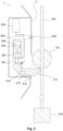
- Figure 2 shows a schematic cross-sectional view of another apparatus embodiment 1 while holding a connector 101 provided on a first elongated hoisting member 100.
- the apparatus embodiment 1 shown in Figure 2 is similar to the embodiment shown in Figures 1A and 1B .
- Several parts and components of the apparatus 1 have been omitted or simplified for illustrative purposes. For example, only one side of the cross-sectional view of the apparatus 1 is shown, this side being on the left-hand side of the first elongated hoisting member 100 as viewed in Figure 2 .
- the mechanism 300 includes an elastic body 314, such as a spring, for tensioning the rotation of the latch 311 towards the stopper 313. This is advantageous for keeping the latch 311 in contact with the stopper 313 when there is no connector 101 being held by the apparatus 1. Also, the use of the apparatus 1 will, by default, be provided with a configuration for holding a connector 101, and this is advantageous in that it increases the safety of using the apparatus 1 and eliminating the possibility of inadvertently letting the connector 101 fall.
- an elastic body 314 such as a spring
- the latch 311 may, instead or in addition to the elastic body 314, be replaced by a latch 311 with the same shape but having a density configured to position the centre of mass of the latch 311 in relation to the pivot 312 so that the latch 311 automatically rotates towards the stopper 313.
- This can be achieved by providing the portion of the latch 311 that intersects the channel 2 with a higher weight than the rest of the latch 311.
- Causing the automatic rotation by means of a density configuration of the latch 311 is advantageous in that it does not require other components, such as the elastic body 314, to be exposed to the seawater and thus reduces the need for maintenance.
- Providing both the elastic body 314 and the density configuration for the latch 311 is advantageous in that the automatic rotation behavior is stronger and more resilient should the elastic body 314 fail.
- the mechanism 300 includes two chambers within the hydraulic cylinder 330: a second chamber 332 (shown in the bottom portion of the hydraulic cylinder 330 in Figure 2 ) for exchanging a hydraulic fluid with the first chamber 320; and a third chamber 334 (shown in the upper portion of the hydraulic cylinder 330 in Figure 2 ) for containing a fluid subjected to the hydrostatic pressure to which the mechanism 300 is subjected.
- the two chambers of the hydraulic cylinder 330 are separated by a piston 333, which is connected to the piston rod 331 that is used for actuating on the latch 311.
- the interior of the third chamber 334 is subjected to the hydrostatic pressure on the exterior of the hydraulic cylinder 330.
- This is schematically illustrated by the opening at the top left corner of the hydraulic cylinder 330. Further openings may be available in the apparatus 1 in locations not shown in the cross-sectional view in Figure 2 that result in the interior of the third chamber 334 being subjected to the hydrostatic pressure to which the apparatus 300 is subjected.
- a device may be additionally provided and hydraulically connected to the third chamber 334 for blocking any sea water from entering the third chamber 334 while enabling the transmission of the hydrostatic pressure. This reduces the need for maintenance of the hydraulic cylinder 330.
- the device may, for example, include a membrane or a fluid that is immiscible with sea water for creating a movable barrier between the sea water and a hydraulic fluid being used within the third chamber 334.
- a membrane or a fluid that is immiscible with sea water for creating a movable barrier between the sea water and a hydraulic fluid being used within the third chamber 334.
- the skilled person will not require inventive skill to develop alternative solutions for both transmitting the hydrostatic pressure to the interior of the third chamber 334 and blocking the sea water from entering the third chamber 334.
- first chamber 320, the second chamber 332 and the valve module 340 form a closed hydraulic circuit.
- first chamber 320 and the second chamber 332 are hydraulically connected to each other and the valve module 340 is used for controlling this hydraulic connection between the first chamber 320 and the second chamber 332.
- the valve module 340 is shown intersecting the hydraulic connection between the first chamber 320 and the second chamber 332.
- the valve module 340 includes a contact switch 342 protruding into the channel 2.
- the contact switch 342 is used for opening a first valve 341, provided within the valve module 340, controlling the hydraulic connection between the first chamber 320 and the second chamber 332.
- the protrusion formed by the contact switch 342 allows a connector 101 being passed through the channel 2 to contact and transversely push the contact switch 342, thus activating the hydraulic connection between the first chamber 320 and the second chamber 332.
- the protrusion of the contact switch 342 is a semi-spherical shape.
- the height of the contact switch 342 as measured from the channel's 2 inner surface is suitable for intersecting the connector's 101 path through the channel 2 while allowing the connector 101 to move past the contact switch 342 when the contact switch is being pressed.
- a skilled person will find alternative shapes for the protrusion of the contact switch 342 within the interior of the channel 2.
- the valve module 340 will be further described below, with reference to figures 3A to 3C .
- the first chamber 320 may include a barrier for blocking the hydraulic fluid, such as a liquid, from being mixed with the compressible fluid, such as a gas, while enabling the exchange of pressure between the two fluids. This advantageously reduces the need for maintenance of the first chamber 320.
- a barrier may, for example, include a membrane, or the compressible fluid may be immiscible with the hydraulic fluid.
- the closed hydraulic circuit formed by the first chamber 320, the second chamber 332 and the valve module 340 makes it possible to transmit pressure in a controlled manner between the piston 333 within the hydraulic cylinder 330 and the compressible fluid within the first chamber 320.
- the hydrostatic pressure transmitted to the interior of the third chamber 334 will, according to the formula of the hydrostatic pressure, increase proportionally to the depth at which the apparatus 1 is positioned.
- the increased hydrostatic pressure transmitted to the interior of the third chamber 334 will increase the pressure applied on the piston 333, which in turn will increase the pressure of the hydraulic fluid between the second chamber 332 and the valve module 340.
- the piston rod 311 will not actuate on the latch 311 if the hydraulic connection between the second chamber 332 and the first chamber 320 is closed by the valve module 340. This is caused due to the piston 33 being obstructed by the hydraulic fluid contained between the second chamber 332 and the valve module 340 and due to the hydraulic fluid typically being incompressible or approximately incompressible. Thus, when the contact switch 343 of the valve module is not being pressed by the connector 101, the hydraulic connection between the two chambers remains closed and the piston rod 331 will not actuate on the latch 311.
- the contact switch 342 can be pressed by lowering the apparatus 1 in relation to the first elongated hoisting member 100 so that the connector 101 is passed against the contact switch 342.
- the valve module 340 will open the hydraulic connection between the second chamber 332 and the first chamber 320, and the piston 333 will react towards balancing the pressure applied on the piston 33 by the third chamber 334 and by the second chamber 320.
- the piston 333 will move downwards (in accordance with the orientation of Figure 2 ) when the hydrostatic pressure applied on the side of the piston 333 facing the third chamber 334 is higher than the pressure applied on the other side of the piston 333 by the hydraulic fluid and the compressible fluid within the first chamber 320.
- the mechanism 300 is capable of being changed to a configuration in which the latch 311 is rotated away from the centre of the channel 2, and the connector 101 can be passed through the channel 2 from the top to the bottom of the apparatus 1 without contacting the latch 311.
- the apparatus 1 can therefore move past the connector 101 while the apparatus 1 is raised.
- configuring the initial pressure of the compressible fluid allows defining a threshold depth until which pressing the contact switch 342 will not cause the piston rod 331 to actuate on the latch 311. For example, if the initial pressure of the compressible fluid in the first chamber 320 is set to 29,42 bar, the contact switch 342 will only cause the piston rod 331 to actuate on the latch 311 after the apparatus 1 has been lowered to more than the threshold depth of 300 meters because this is the depth at which the hydrostatic pressure is expected to be 29,42 bar.
- Configuring the initial pressure of the compressible fluid can be advantageous in increasing the safety of using the apparatus 1 because the contact switch 342 can be inadvertently pressed by a connector 101 before the apparatus 1 reaches an intended depth and this will not cause the latch 311 to be actuated by the piston rod 331.
- FIGS 3A-3C show schematic views of valve module embodiments 340 that could be used as the valve modules 340 shown in Figures 1A and 2 .
- Figure 3A shows a valve module 340 including a first control valve 341 for controlling the hydraulic connection between the first chamber 320 and the second chamber 332.
- the first control valve 341 includes two hydraulic terminals. A top terminal is illustrated as being hydraulically connected to the top of the valve module 340 shown in Figure 3A , and this terminal connects to the first chamber 320. A bottom terminal is illustrated as being hydraulically connected to the bottom of the valve module 340 shown in Figure 3A , and this terminal connects to the second chamber 332. Also, the first control valve 341 can be activated by the contact switch 342.
- the first control valve 341 is closed unless the contact switch 342 is being pressed.
- Figure 3B shows a valve module embodiment 340 that has similarities with the embodiment shown in Figure 3A .
- a difference of the valve module 340 shown in Figure 3B is that a one-way valve 343 is included and arranged in parallel to the first control valve 341.
- the one-way valve 343 is oriented to permit a free flow only from the top terminal, i.e. the hydraulically connection of the first control valve 341 to the first chamber 320, to the bottom terminal, i.e. the hydraulic connection of the first control valve 341 to the second chamber 332.
- This valve module embodiment 340 is advantageous in that it enables the compressible fluid within the first chamber 320 to depressurize whenever the pressure within the second chamber 332 is lower than the pressure within the first chamber 320. This automatic depressurization is achieved without requiring the activation of the contact switch 342.
- the one-way valve 343 will enable the transmission of any excess pressure from the top terminal to the bottom terminal of the first control valve 341 and thus keep the pressure of the compressible fluid within the first chamber 320 to be at most the pressure of the hydraulic fluid between the second chamber 332 and the first control valve 341.
- Figure 3C shows a valve module embodiment 340 that has similarities with the embodiment shown in Figure 3B .
- a second control valve 344 is included for controlling the hydraulic connection between the first control valve 341 and the second chamber 334.
- the second control valve 344 can be used for closing the hydraulic connection between the second chamber 332 and the first chamber 320 independently of the hydrostatic pressure or the activation of the contact switch 342.
- the second control valve 344 is open by default and closed only when it has been configured to be closed.
- the apparatus 1 can be controlled to perform the following movements: lowering the apparatus 1 to move past a connector 101 at a lower depth on a first elongated hoisting member 100; once the apparatus 1 has moved past the connector 101, raising the apparatus 1 so that the passed connector 101 is held and raised by the apparatus 1; repeating these steps until the first elongated hoisting member 100 has been decreased as intended.
- closing the second control valve 344 is advantageous in that a higher safety is provided due to the inability of the connector 101 to inadvertently press the contact switch 342 and cause the connector 101 to be abruptly dropped.
- the apparatus 1 includes a third control valve 335 for controlling a hydraulic connection transmitting the hydrostatic pressure into the third chamber 334. Closing this valve blocks the interior of the third chamber 334 from being subjected to the hydrostatic pressure applied on the apparatus 1.
- the third control valve 335 can be advantageous in increasing the safety of the apparatus 1 similarly to the second control valve 344 described above with reference to Figure 3C .
- FIGS 4A and 4B show a situation in which a subsea hoisting operation is being carried out.
- a load 102 is being moved by a system embodiment based on a floating vessel 10.
- the floating vessel 10 is shown as a trapezoid and the load 102 is shown as a square.
- the system components and proportions in Figures 4A and 4B are shown in a simplified manner.
- the distance between the floating vessel 10 and the seabed 20 in a deep-water operation may be in the order of thousands of metres.
- the system shown in Figures 4A and 4B deals with the challenges of handling a heavy steel wire rope using an arrangement of ropes similar to the ones described in WO 2009/005359 A1 and WO 2010/093251 A1 .
- the system includes two elongated hoisting members: a fibre rope 100 for suspending the load 102; and a steel wire rope 200 for suspending an apparatus 1 embodiment according to the present disclosure.
- the two elongated hoisting members, i.e. the fibre rope 100 and the steel wire rope 200 can be independently made longer or shorter from the floating vessel 10. This capability is illustrated by the two winches shown on the floating vessel 10, one shown at the top of a crane mast on the floating vessel 10 and the other winch being on the main deck of the floating vessel 10.
- the apparatus 1 and the fibre rope 100 have been arranged so that the fibre rope 100 runs through a channel 2 crossing the apparatus 1. This restricts the movements of the apparatus 1 so that it may be moved up or down along the fibre rope 100.
- the system can move the apparatus 1 to a position along the fiber rope 100. The range of positions that can be reached by the apparatus 1 depends on the length of the steel wire rope 200.
- the apparatus 1 can hold a component provided at a fixed position on the fibre rope 100.
- the fibre rope 100 includes two connectors 101 at fixed positions: a lower connector 101 can be observed within the apparatus 1 in Figure 1A as a dashed circle; and an upper connector can be observed as a circle with a solid line fixed to the fibre rope 100 at an upper position closer to the floating vessel 10. The same two connectors are observed in Figure 1B but the lower connector 101 is no longer shown within the apparatus 1.
- the connectors 101 can be implemented as a solid objects or devices provided at a fixed position on the fibre rope 100.
- the connector 101 is schematically shown as a sphere encircling a position on the fibre rope 100.
- the skilled will be able to use a connector 101 based on other shapes and kinds of fixture without requiring inventive skill.
- the connectors 101 may be of the type disclosed in EP 3670961 A1 , in which the connectors, rather than encircling a fibre rope 100, are used to splice ends of fibre rope segments together.
- the connector may be barrel shaped with a slightly enlarged diameter over its midportion.
- the apparatus 1 can hold a connector 101 when the apparatus 1 is raised along the fibre rope 101 and the connector 101 enters the channel of the apparatus 1.
- the system can suspend the connector 101 using the steel wire rope 200.
- the connector 101 is fixed on the fibre rope 100, the system can suspend the portion of the fiber rope 100 between the load 102 and the connector 101 using the mechanical connection established between the apparatus 1 and the connector 101.
- a first mode of suspension shown in Figure 4A
- the weight of the load 102 is transmitted to the floating vessel 10 by two rope segments: a rope segment between the load 102 and the apparatus 1, this segment being provided by a portion of the fibre rope 100; and another rope segment between the floating vessel 10 and the apparatus 1, this segment being provided by the steel wire rope 200.
- This mode of suspension requires the apparatus 1 to hold a connector 101, which is shown as a dashed circle within the apparatus 1 in Figure 4A .
- the weight of the load 102 is transmitted from the apparatus 1 to the floating vessel 10 only through the steel wire rope 200 and this has the advantage of limiting the execution of bending cycles under load only to the steel wire rope 200 and keeping the fibre rope 100 free from deterioration due to this type of bending cycle. Moreover, it can be observed that the fibre rope 100 segment between the load 102 and the apparatus 1 is subjected to the weight of the load 102 but not subjected to bending cycles.
- the first mode of suspension is advantageous for moving the load 102 between two submerged positions.
- the additional slack is sufficiently long to avoid having any weight of the load 102 being transmitted through the fibre rope 100 above the apparatus 1 but not long enough that it becomes possible for the fibre rope 100 to get inadvertently wound around or stuck into other components of the system or the load 102.
- the added slack has a length equivalent to the perimeter of at least one turn of a drum being used on the floating vessel 10 for controlling the extended length of the fibre rope 100.
- a second mode of suspension shown in Figure 4B , the weight of the load 102 is transmitted to the floating vessel 10 entirely by the fibre rope 100.
- This mode is useful for moving the apparatus 1 along the fibre rope 100 while maintaining the length of the fibre rope 100 between the floating vessel 10 and the load 102. It can be observed in Figure 4B that the apparatus 1 is suspended at an intermediate position between the two connectors 101 on the fiber rope 100 and can be raised or lowered as needed.
- Switching the system from the first mode of suspension to the second mode of suspension can be achieved by altering the lengths of the elongated hoisting members so that the apparatus 1 no longer holds the connector 101.
- altering the lengths is meant to spool in/out the elongated hoisting members by means of winches provided on the floating vessel 10, as will be understood by a person skilled in the art.
- the elongated hoisting members can be controlled to lower the apparatus 1 in relation to the fibre rope 100 and, at some moment, cause the weight of the load 102 to be transmitted to the floating vessel 10 entirely through the fibre rope 100.
- Switching from the second mode of suspension to the first mode of suspension can be achieved in an opposite manner.
- the apparatus 1 can be raised until it encounters a connector 101 and the latter enters the channel of the apparatus 1.
- the apparatus 1 will hold the connector 101 and this will cause the weight of the load 102 to be transmited to the floating vessel 10 in accordance with the first mode of suspension.
- the system can be operated so that it only changes the extended length of the fibre rope 100 during the first mode of operation while having the steel wire rope 200 perform all the bending cycles under load.
- the length of the fibre rope 100 extended from the floating vessel 10 may be kept constant and the steel wire rope 200 may be made longer or shorter to position the apparatus 1 as needed. Therefore, the fibre rope 100 is kept free from deterioration due to bending cycles under load both during the modes of suspension and the switching moments between modes of suspension. This maximizes the lifetime of the fibre rope 100.
- the predictability of when the fibre rope 100 should be replaced will be improved because the fibre rope 100 will only be used under load when kept still. The higher predictability results in a higher safety.
- apparatus 1 In an opposite situation, i.e. by observing Figure 4B firstly and Figure 4A secondly, the apparatus 1 also requires the ability to move past the lower connector 101. It can be seen that, before the system changed to the first mode of suspension, the apparatus 1 first had to be moved past the lower connector 1 to reach a position on the fibre rope 100 below the lower connector 101 and then be raised to hold the connector 101. Thus, apparatus 1 includes features for moving past a connector 101 when the apparatus 1 is being lowered.
- moving the load 102 between two submerged positions separated by a distance longer than the length of the steel wire rope 200 can be achieved by continuously alternating between the first and second modes of suspension until the target submerged position is reached.
- the steel wire rope 200 is used for performing bending cycles under load in the direction of the lowering or raising operation being carried out
- the steel wire rope 200 is used for moving the apparatus 1 in the opposite direction.
- the system can be useful for lowering, raising, or lowering and raising a load 102 between two submerged positions reachable by the fibre rope 100.
- the efficiency of these steps can be improved by maximizing a threshold length of the steel wire rope 200 at which the system stops extending both the fibre rope 100 and the steel wire rope 200 and switches to the second mode of suspension.
- a threshold length equal to the total maximum length minus a safety margin length, such as 2 to 5 meters.
- the safety margin length allows the system to still have some steel wire rope 200 available to perform the step of switching to the second mode of suspension. The skilled person will find several possibilities for suitable maximum total and safety margin lengths.
- Maximizing the length of the steel wire rope 200 at which the system switches to the second mode of suspension also has the advantage of minimizing the aggregate time during which the second mode of suspension is performed with the fibre rope 100 kept with a constant length waiting for the apparatus 1 to be repositioned and connected to the next connector 101 at an upper position on the fibre rope 100.
- the efficiency of raising the load 102 over a distance longer than the length of the steel wire rope 200 may also be improved. This can be achieved by maximizing a threshold length of the steel wire rope 200 at which the system switches to the first mode of suspension after having extended the length of the steel wire rope 200. For example, with a steel wire rope 200 embodiment with a total maximum length of 300 meters, it can be useful to establish the threshold length as being equal to the maximum total length of the steel wire rope 200.
- Maximizing the length of the steel wire rope 200 at which the system switches to the second mode of suspension also has the advantage of minimizing the aggregated time during which the second mode of suspension is performed with the fibre rope 100 kept with a constant length waiting for the apparatus 1 to be repositioned and connected to the next connector 101 at a lower position on the fibre rope 100.
- the system embodiment can be provided with appropriate dimensions and parameters for the operations that will be performed. In some situations, it may be useful to provide the fibre rope 100 with a length that is sufficient to reach the seabed 20 from the floating vessel 10, while the steel wire rope 200 may be provided with a length corresponding to a portion of the distance between the floating vessel 10 and the seabed 20 so that a balance is established between the maximum total length of the steel wire rope 200 and the necessary requirements imposed on the floating vessel 10 in order to hoist the steel wire rope 200. For example, in one embodiment suitable for deep-water hoisting operations the fibre rope 100 may have a total length of at least 3000 meters and the steel wire rope 200 a length of at least 300 meters.
Landscapes
- Engineering & Computer Science (AREA)
- Mechanical Engineering (AREA)
- General Engineering & Computer Science (AREA)
- Life Sciences & Earth Sciences (AREA)
- Geology (AREA)
- Mining & Mineral Resources (AREA)
- Ocean & Marine Engineering (AREA)
- Combustion & Propulsion (AREA)
- Chemical & Material Sciences (AREA)
- General Life Sciences & Earth Sciences (AREA)
- Geochemistry & Mineralogy (AREA)
- Civil Engineering (AREA)
- Structural Engineering (AREA)
- Fluid Mechanics (AREA)
- Environmental & Geological Engineering (AREA)
- Physics & Mathematics (AREA)
- Load-Engaging Elements For Cranes (AREA)
Claims (14)
- Vorrichtung (1) zum Aufhängen eines Verbinders (101), der an einem ersten länglichen Hebeelement (100) bereitgestellt ist, während eines Unterwasser-Hebevorgangs,wobei die Vorrichtung (1) einen Mechanismus (300) zum Halten des Verbinders (101) umfasst,dadurch gekennzeichnet, dass, wenn der Mechanismus (300) einem hydrostatischen Druck oberhalb eines Schwellendrucks ausgesetzt ist, der Mechanismus (300) in eine Konfiguration zum Vorbeibewegen an dem Verbinder (101) veränderbar ist, während die Vorrichtung (1) angehoben wird.
- Vorrichtung (1) nach Anspruch 1, wobei der Mechanismus (300) umfasst:- eine erste Kammer (320) zur Aufnahme eines komprimierbaren Fluids;- einen Hydraulikzylinder (330), umfassend eine zweite Kammer (332), die hydraulisch mit der ersten Kammer (320) verbunden werden kann, und eine dritte Kammer (334), die ein Fluid enthält, das einem hydrostatischen Druck ausgesetzt ist, wobei die zweite Kammer (332) und die dritte Kammer (334) durch einen Kolben (333) voneinander getrennt sind; und- ein erstes Steuerventil (341) zum Steuern der hydraulischen Verbindung zwischen der ersten Kammer (320) und der zweiten Kammer (332); und- ein Kontaktschalter (342) zum Aktivieren des ersten Steuerventils (341), wenn der Verbinder (101) auf den Kontaktschalter (342) einwirkt.
- Vorrichtung (1) nach Anspruch 2, wobei die Vorrichtung (1) ein Einwegventil (343) umfasst, das parallel zu dem ersten Steuerventil (341) angeordnet ist, wobei das Einwegventil (343) so ausgerichtet ist, dass es einen freien Fluss nur von einer hydraulischen Verbindung des ersten Steuerventils (341) zu der ersten Kammer (320) zu einer anderen hydraulischen Verbindung des ersten Steuerventils (341) zu der zweiten Kammer (332) ermöglicht.
- Vorrichtung (1) nach einem der Ansprüche 2 bis 3, wobei die Vorrichtung (1) ein zweites Steuerventil (344) zum Steuern einer hydraulischen Verbindung zwischen dem ersten Steuerventil (341) und der zweiten Kammer (332) umfasst.
- Vorrichtung (1) nach einem der Ansprüche 2 bis 4, wobei die Vorrichtung (1) ein drittes Steuerventil (335) zum Steuern einer hydraulischen Verbindung umfasst, die einen hydrostatischen Druck in die dritte Kammer (334) überträgt.
- Vorrichtung (1) nach einem der Ansprüche 1 bis 5, wobei der Mechanismus (300) umfasst:- eine Sperrklinke (311) zum Halten des Verbinders (101);- einen Drehzapfen (312), an dem die Sperrklinke (311) drehbar ist; und- ein Anschlag (313), der in Bezug auf den Drehzapfen (312) so angeordnet ist, dass die Drehung der Sperrklinke (311) an einer Position gestoppt werden kann, wobei der Verbinder (101) durch die Sperrklinke (311) gehalten werden kann.
- Vorrichtung (1) nach einem der Ansprüche 2 bis 5 und nach Anspruch 6, wobei der Hydraulikzylinder (330) so angeordnet ist, dass die Sperrklinke (311) durch eine Kolbenstange (331) betätigt werden kann, die mit dem Kolben (333) des Hydraulikzylinders (330) verbunden ist, wobei die Betätigung durch die Kolbenstange (331) bewirkt, dass sich die Sperrklinke (311) in eine Position dreht, in der der Mechanismus (300) an dem Verbinder (101) vorbeibewegt wird, während die Vorrichtung (1) angehoben wird.
- Vorrichtung (1) nach einem der Ansprüche 6 bis 7, wobei der Mechanismus (300) einen elastischen Körper (314) zum Spannen der Drehung der Sperrklinke (311) in Richtung des Anschlags (313) umfasst.
- Vorrichtung (1) nach einem der Ansprüche 6 bis 8, wobei die Sperrklinke (311) eine Dichte umfasst, die konfiguriert ist, um den Schwerpunkt der Sperrklinke (311) in Bezug auf den Drehzapfen (312) so zu positionieren, dass sich die Sperrklinke (311) automatisch in Richtung des Anschlags (313) dreht.
- Vorrichtung (1) nach einem der Ansprüche 1 bis 9, wobei die Vorrichtung (1) einen Kanal (2) zum Durchführen des Verbinders (101) durch die Vorrichtung (1) umfasst,
wobei der Mechanismus (300) in Bezug auf den Kanal (2) so angeordnet ist, dass der Verbinder (101) in dem Kanal (2) gehalten werden kann. - Vorrichtung (1) nach einem der Ansprüche 2 bis 5 und nach Anspruch 10, wobei der Kontaktschalter (342) angeordnet ist, um in den Kanal (2) hineinzuragen.
- System zum Bewegen einer Last (102) zwischen einem schwimmenden Schiff (10) und einer Unterwasserposition,
wobei das System umfasst:- eine Vorrichtung (1) wie in einem der Ansprüche 1 bis 11 beschrieben;- ein erstes längliches Hebeelement (100) zum Aufhängen der Last (102), wobei das erste längliche Hebeelement (100) mindestens einen Verbinder (101) umfasst, der von der Vorrichtung (1) gehalten wird; und- ein zweites längliches Hebeelement (200) zum Aufhängen der Vorrichtung (1). - Verfahren zum Absenken einer Last (102) von einem schwimmenden Schiff (10) in eine Unterwasserposition,
dadurch gekennzeichnet, dass das Verfahren die folgenden Schritte umfasst:- Bereitstellen eines Systems wie in Anspruch 12 beschrieben,- Aufhängen, in einer ersten Art der Aufhängung, der Vorrichtung (1) an dem schwimmenden Schiff (10) unter Verwendung einer Länge des zweiten länglichen Hebeelements (200) und der Last (102) an der Vorrichtung (1) unter Verwendung eines Abschnitts einer Länge des ersten länglichen Hebeelements (100), während der Mechanismus (300) einen Verbinder (101) hält, der an dem ersten länglichen Hebeelement (100) bereitgestellt ist;- Verlängern, während die erste Art der Aufhängung beibehalten wird, sowohl der Länge des ersten länglichen Hebeelements (100) als auch der Länge des zweiten länglichen Hebeelements (200) vom schwimmenden Schiff (10) aus, bis der Mechanismus (300) der Vorrichtung (1) einem hydrostatischen Druck oberhalb eines Schwellendrucks ausgesetzt ist;- Aufhängen, in einer zweiten Art der Aufhängung, der Last (102) an dem schwimmenden Schiff (10) unter Verwendung der Länge des ersten länglichen Hebeelements (100);- Ändern, während die zweite Art der Aufhängung beibehalten wird, des Mechanismus (300) in eine Konfiguration, um sich am Verbinder (101) vorbeizubewegen, während die Vorrichtung (1) angehoben wird. - Verfahren zum Heben einer Last (102) aus einer Unterwasserposition in Richtung eines schwimmenden Schiffs (10),
dadurch gekennzeichnet, dass das Verfahren die folgenden Schritte umfasst:- Bereitstellen eines Systems wie in Anspruch 12 beschrieben;- Aufhängen, in einer zweiten Art der Aufhängung, der Last (102) an dem schwimmenden Schiff (10) unter Verwendung einer Länge des ersten länglichen Hebeelements (100);- Verlängern, während die zweite Art der Aufhängung beibehalten wird, einer Länge des zweiten länglichen Hebeelements (200), bis sich der Mechanismus (300) der Vorrichtung (1) an einem am ersten länglichen Hebeelement (100) bereitgestellten Verbinder (101) vorbeibewegt;- Aufhängen, in einer ersten Art der Aufhängung, der Vorrichtung (1) an dem schwimmenden Schiff (10) unter Verwendung einer Länge des zweiten länglichen Hebeelements (200) und der Last (102) an der Vorrichtung (1) unter Verwendung eines Abschnitts der Länge des ersten länglichen Hebeelements (100), während der Mechanismus (300) den Verbinder (101) hält;- Verringern, während die erste Art der Aufhängung beibehalten wird, sowohl der Länge des ersten länglichen Hebeelements (100) als auch der Länge des zweiten länglichen Hebeelements (200) vom schwimmenden Schiff (10) aus.
Applications Claiming Priority (1)
| Application Number | Priority Date | Filing Date | Title |
|---|---|---|---|
| PCT/NO2021/050037 WO2022169367A1 (en) | 2021-02-08 | 2021-02-08 | Apparatus, system and methods for moving a load between a floating vessel and a submerged position |
Publications (2)
| Publication Number | Publication Date |
|---|---|
| EP4288368A1 EP4288368A1 (de) | 2023-12-13 |
| EP4288368B1 true EP4288368B1 (de) | 2024-11-20 |
Family
ID=74871801
Family Applications (1)
| Application Number | Title | Priority Date | Filing Date |
|---|---|---|---|
| EP21711658.1A Active EP4288368B1 (de) | 2021-02-08 | 2021-02-08 | Vorrichtung, system und verfahren zum bewegen einer last zwischen einem schwimmenden schiff und einer unterwasserposition |
Country Status (4)
| Country | Link |
|---|---|
| US (1) | US12509189B2 (de) |
| EP (1) | EP4288368B1 (de) |
| DK (1) | DK4288368T3 (de) |
| WO (1) | WO2022169367A1 (de) |
Family Cites Families (19)
| Publication number | Priority date | Publication date | Assignee | Title |
|---|---|---|---|---|
| US3807334A (en) * | 1973-09-17 | 1974-04-30 | Us Navy | Motion compensating device for surface supported underwater structures |
| US4078509A (en) * | 1976-05-27 | 1978-03-14 | The United States Of America As Represented By The Secretary Of The Navy | Salvage apparatus and method |
| CA2140547A1 (en) * | 1991-01-25 | 1994-02-03 | James Edward Stangroom | A method of raising objects from the sea b |
| US5190107A (en) | 1991-04-23 | 1993-03-02 | Shell Oil Company | Heave compensated support system for positioning subsea work packages |
| US6390012B1 (en) * | 1999-09-20 | 2002-05-21 | Coflexip, S.A. | Apparatus and method for deploying, recovering, servicing, and operating an autonomous underwater vehicle |
| US6752100B2 (en) * | 2002-05-28 | 2004-06-22 | Shell Oil Company | Apparatuses and methods of deploying and installing subsea equipment |
| AU2003251461A1 (en) * | 2002-07-30 | 2004-02-23 | Single Buoy Moorings Inc | Floating lowering and lifting device |
| NO330923B1 (no) | 2007-07-05 | 2011-08-15 | Nat Oilwell Norway As | Fremgangsmate for a heise et kolli til havs |
| NO333202B1 (no) | 2009-02-16 | 2013-04-08 | Nat Oilwell Varco Norway As | Fremgangsmate og anordning for a heise et kolli fra en kran |
| ITMI20091639A1 (it) * | 2009-09-25 | 2011-03-26 | Saipem Spa | Metodo e gruppo di sollevamento per abbandonare e/o recuperare una tubazione subacquea tramite un natante di posa e natante di posa equipaggiato con tale gruppo di sollevamento |
| IT1396585B1 (it) * | 2009-10-23 | 2012-12-14 | Saipem Spa | Metodo per abbandonare una tubazione subacquea su un letto di un corpo d'acqua |
| US20110286802A1 (en) * | 2010-05-21 | 2011-11-24 | Jacobs Engineering Group | Improved Subsea Riser System |
| GB2486697B (en) * | 2010-12-23 | 2013-05-29 | Tidal Generation Ltd | Power generating equipment |
| US9855999B1 (en) * | 2014-01-10 | 2018-01-02 | Wt Industries, Llc | System for launch and recovery of remotely operated vehicles |
| DK2896589T3 (en) * | 2014-01-17 | 2017-01-23 | Sal Heavy Lift Gmbh | Method and apparatus. |
| US9487272B2 (en) * | 2014-03-14 | 2016-11-08 | Intermoor, Inc. | Systems and methods for tensioning mooring lines at the seafloor |
| PL237989B1 (pl) * | 2018-05-09 | 2021-06-28 | Akademia Gorniczo Hutnicza Im Stanislawa Staszica W Krakowie | Sposób transportu i autonomiczne urządzenie do transportu ładunku w wodzie, zwłaszcza z głębin |
| EP3670961B1 (de) | 2018-12-20 | 2023-11-01 | Grant Prideco, Inc. | Seilverbinder zum verbinden von vorbereiteten enden zweier seilsegmente, ein seilverlängerungssystem und ein hubsystem mit solch einem seilverbinder |
| GB2584659B (en) * | 2019-06-07 | 2021-12-22 | Subsea 7 Ltd | Deployment of unmanned underwater vehicles |
-
2021
- 2021-02-08 EP EP21711658.1A patent/EP4288368B1/de active Active
- 2021-02-08 DK DK21711658.1T patent/DK4288368T3/da active
- 2021-02-08 US US18/273,960 patent/US12509189B2/en active Active
- 2021-02-08 WO PCT/NO2021/050037 patent/WO2022169367A1/en not_active Ceased
Also Published As
| Publication number | Publication date |
|---|---|
| WO2022169367A1 (en) | 2022-08-11 |
| EP4288368A1 (de) | 2023-12-13 |
| US20240409189A1 (en) | 2024-12-12 |
| US12509189B2 (en) | 2025-12-30 |
| DK4288368T3 (da) | 2024-12-16 |
Similar Documents
| Publication | Publication Date | Title |
|---|---|---|
| CN110382346B (zh) | 深水升降系统以及方法 | |
| KR102051366B1 (ko) | 크레인선 | |
| EP2477927B1 (de) | Hebeanlage | |
| EP1509672B1 (de) | Vorrichtungen und verfahren zum einsetzen und installieren von unterwasserausrüstung | |
| US3681928A (en) | Method and apparatus for carrying out underwater well operations | |
| EP2379404B1 (de) | Hubgerät und methode zum heben einer last | |
| US9487272B2 (en) | Systems and methods for tensioning mooring lines at the seafloor | |
| RU2182883C2 (ru) | Устройство для опускания груза на глубоководном участке | |
| EP0365672B1 (de) | Befestigung eines kranhakens mit in tiefwasser ausgedehntem arbeitsbereich | |
| US7182212B2 (en) | Floating lifting device | |
| CN211056582U (zh) | 科考船被动补偿绞车系统 | |
| US4471709A (en) | Pretensioned catenary free deep sea mooring system | |
| EP4288368B1 (de) | Vorrichtung, system und verfahren zum bewegen einer last zwischen einem schwimmenden schiff und einer unterwasserposition | |
| US20120199800A1 (en) | Hoisting assembly | |
| NO20170862A1 (en) | A mooring system | |
| EP3411290B1 (de) | Verankerungsverbinderanordnung | |
| CN113007182B (zh) | 一种锚链提升器液压系统、装置及装置的使用方法 | |
| US3638338A (en) | Apparatus and method for deep sea dredging | |
| KR101067365B1 (ko) | 도르래를 이용한 승강장치 | |
| NL2035649B1 (en) | Crane system including a tugger winch and tugger line. | |
| GB2187159A (en) | Improvements relating to apparatus for supporting and manipulating objects | |
| RU2755358C1 (ru) | Грузоподъемное устройство для подъема затонувших объектов | |
| KR101834316B1 (ko) | 해상 부유체 계류 시스템 | |
| CA3051642C (en) | Mooring connector assembly | |
| WO2026017556A1 (en) | Crane |
Legal Events
| Date | Code | Title | Description |
|---|---|---|---|
| STAA | Information on the status of an ep patent application or granted ep patent |
Free format text: STATUS: UNKNOWN |
|
| STAA | Information on the status of an ep patent application or granted ep patent |
Free format text: STATUS: THE INTERNATIONAL PUBLICATION HAS BEEN MADE |
|
| PUAI | Public reference made under article 153(3) epc to a published international application that has entered the european phase |
Free format text: ORIGINAL CODE: 0009012 |
|
| STAA | Information on the status of an ep patent application or granted ep patent |
Free format text: STATUS: REQUEST FOR EXAMINATION WAS MADE |
|
| 17P | Request for examination filed |
Effective date: 20230612 |
|
| AK | Designated contracting states |
Kind code of ref document: A1 Designated state(s): AL AT BE BG CH CY CZ DE DK EE ES FI FR GB GR HR HU IE IS IT LI LT LU LV MC MK MT NL NO PL PT RO RS SE SI SK SM TR |
|
| P01 | Opt-out of the competence of the unified patent court (upc) registered |
Effective date: 20231213 |
|
| DAV | Request for validation of the european patent (deleted) | ||
| DAX | Request for extension of the european patent (deleted) | ||
| GRAP | Despatch of communication of intention to grant a patent |
Free format text: ORIGINAL CODE: EPIDOSNIGR1 |
|
| STAA | Information on the status of an ep patent application or granted ep patent |
Free format text: STATUS: GRANT OF PATENT IS INTENDED |
|
| INTG | Intention to grant announced |
Effective date: 20240816 |
|
| GRAS | Grant fee paid |
Free format text: ORIGINAL CODE: EPIDOSNIGR3 |
|
| GRAA | (expected) grant |
Free format text: ORIGINAL CODE: 0009210 |
|
| STAA | Information on the status of an ep patent application or granted ep patent |
Free format text: STATUS: THE PATENT HAS BEEN GRANTED |
|
| AK | Designated contracting states |
Kind code of ref document: B1 Designated state(s): AL AT BE BG CH CY CZ DE DK EE ES FI FR GB GR HR HU IE IS IT LI LT LU LV MC MK MT NL NO PL PT RO RS SE SI SK SM TR |
|
| REG | Reference to a national code |
Ref country code: GB Ref legal event code: FG4D |
|
| REG | Reference to a national code |
Ref country code: CH Ref legal event code: EP |
|
| REG | Reference to a national code |
Ref country code: NL Ref legal event code: FP |
|
| REG | Reference to a national code |
Ref country code: DE Ref legal event code: R096 Ref document number: 602021022072 Country of ref document: DE |
|
| REG | Reference to a national code |
Ref country code: DK Ref legal event code: T3 Effective date: 20241209 |
|
| REG | Reference to a national code |
Ref country code: IE Ref legal event code: FG4D |
|
| REG | Reference to a national code |
Ref country code: LT Ref legal event code: MG9D |
|
| PG25 | Lapsed in a contracting state [announced via postgrant information from national office to epo] |
Ref country code: PT Free format text: LAPSE BECAUSE OF FAILURE TO SUBMIT A TRANSLATION OF THE DESCRIPTION OR TO PAY THE FEE WITHIN THE PRESCRIBED TIME-LIMIT Effective date: 20250320 Ref country code: IS Free format text: LAPSE BECAUSE OF FAILURE TO SUBMIT A TRANSLATION OF THE DESCRIPTION OR TO PAY THE FEE WITHIN THE PRESCRIBED TIME-LIMIT Effective date: 20250320 Ref country code: HR Free format text: LAPSE BECAUSE OF FAILURE TO SUBMIT A TRANSLATION OF THE DESCRIPTION OR TO PAY THE FEE WITHIN THE PRESCRIBED TIME-LIMIT Effective date: 20241120 |
|
| PG25 | Lapsed in a contracting state [announced via postgrant information from national office to epo] |
Ref country code: FI Free format text: LAPSE BECAUSE OF FAILURE TO SUBMIT A TRANSLATION OF THE DESCRIPTION OR TO PAY THE FEE WITHIN THE PRESCRIBED TIME-LIMIT Effective date: 20241120 |
|
| REG | Reference to a national code |
Ref country code: AT Ref legal event code: MK05 Ref document number: 1743431 Country of ref document: AT Kind code of ref document: T Effective date: 20241120 |
|
| PG25 | Lapsed in a contracting state [announced via postgrant information from national office to epo] |
Ref country code: BG Free format text: LAPSE BECAUSE OF FAILURE TO SUBMIT A TRANSLATION OF THE DESCRIPTION OR TO PAY THE FEE WITHIN THE PRESCRIBED TIME-LIMIT Effective date: 20241120 |
|
| PG25 | Lapsed in a contracting state [announced via postgrant information from national office to epo] |
Ref country code: ES Free format text: LAPSE BECAUSE OF FAILURE TO SUBMIT A TRANSLATION OF THE DESCRIPTION OR TO PAY THE FEE WITHIN THE PRESCRIBED TIME-LIMIT Effective date: 20241120 |
|
| PG25 | Lapsed in a contracting state [announced via postgrant information from national office to epo] |
Ref country code: GR Free format text: LAPSE BECAUSE OF FAILURE TO SUBMIT A TRANSLATION OF THE DESCRIPTION OR TO PAY THE FEE WITHIN THE PRESCRIBED TIME-LIMIT Effective date: 20250221 Ref country code: LV Free format text: LAPSE BECAUSE OF FAILURE TO SUBMIT A TRANSLATION OF THE DESCRIPTION OR TO PAY THE FEE WITHIN THE PRESCRIBED TIME-LIMIT Effective date: 20241120 Ref country code: AT Free format text: LAPSE BECAUSE OF FAILURE TO SUBMIT A TRANSLATION OF THE DESCRIPTION OR TO PAY THE FEE WITHIN THE PRESCRIBED TIME-LIMIT Effective date: 20241120 |
|
| PG25 | Lapsed in a contracting state [announced via postgrant information from national office to epo] |
Ref country code: PL Free format text: LAPSE BECAUSE OF FAILURE TO SUBMIT A TRANSLATION OF THE DESCRIPTION OR TO PAY THE FEE WITHIN THE PRESCRIBED TIME-LIMIT Effective date: 20241120 |
|
| PG25 | Lapsed in a contracting state [announced via postgrant information from national office to epo] |
Ref country code: RS Free format text: LAPSE BECAUSE OF FAILURE TO SUBMIT A TRANSLATION OF THE DESCRIPTION OR TO PAY THE FEE WITHIN THE PRESCRIBED TIME-LIMIT Effective date: 20250220 |
|
| PG25 | Lapsed in a contracting state [announced via postgrant information from national office to epo] |
Ref country code: SM Free format text: LAPSE BECAUSE OF FAILURE TO SUBMIT A TRANSLATION OF THE DESCRIPTION OR TO PAY THE FEE WITHIN THE PRESCRIBED TIME-LIMIT Effective date: 20241120 |
|
| PG25 | Lapsed in a contracting state [announced via postgrant information from national office to epo] |
Ref country code: EE Free format text: LAPSE BECAUSE OF FAILURE TO SUBMIT A TRANSLATION OF THE DESCRIPTION OR TO PAY THE FEE WITHIN THE PRESCRIBED TIME-LIMIT Effective date: 20241120 |
|
| PG25 | Lapsed in a contracting state [announced via postgrant information from national office to epo] |
Ref country code: RO Free format text: LAPSE BECAUSE OF FAILURE TO SUBMIT A TRANSLATION OF THE DESCRIPTION OR TO PAY THE FEE WITHIN THE PRESCRIBED TIME-LIMIT Effective date: 20241120 |
|
| PG25 | Lapsed in a contracting state [announced via postgrant information from national office to epo] |
Ref country code: SK Free format text: LAPSE BECAUSE OF FAILURE TO SUBMIT A TRANSLATION OF THE DESCRIPTION OR TO PAY THE FEE WITHIN THE PRESCRIBED TIME-LIMIT Effective date: 20241120 |
|
| PG25 | Lapsed in a contracting state [announced via postgrant information from national office to epo] |
Ref country code: CZ Free format text: LAPSE BECAUSE OF FAILURE TO SUBMIT A TRANSLATION OF THE DESCRIPTION OR TO PAY THE FEE WITHIN THE PRESCRIBED TIME-LIMIT Effective date: 20241120 |
|
| PG25 | Lapsed in a contracting state [announced via postgrant information from national office to epo] |
Ref country code: IT Free format text: LAPSE BECAUSE OF FAILURE TO SUBMIT A TRANSLATION OF THE DESCRIPTION OR TO PAY THE FEE WITHIN THE PRESCRIBED TIME-LIMIT Effective date: 20241120 |
|
| REG | Reference to a national code |
Ref country code: DE Ref legal event code: R097 Ref document number: 602021022072 Country of ref document: DE |
|
| REG | Reference to a national code |
Ref country code: DE Ref legal event code: R119 Ref document number: 602021022072 Country of ref document: DE |
|
| PG25 | Lapsed in a contracting state [announced via postgrant information from national office to epo] |
Ref country code: SE Free format text: LAPSE BECAUSE OF FAILURE TO SUBMIT A TRANSLATION OF THE DESCRIPTION OR TO PAY THE FEE WITHIN THE PRESCRIBED TIME-LIMIT Effective date: 20241120 |
|
| PG25 | Lapsed in a contracting state [announced via postgrant information from national office to epo] |
Ref country code: MC Free format text: LAPSE BECAUSE OF FAILURE TO SUBMIT A TRANSLATION OF THE DESCRIPTION OR TO PAY THE FEE WITHIN THE PRESCRIBED TIME-LIMIT Effective date: 20241120 |
|
| PLBE | No opposition filed within time limit |
Free format text: ORIGINAL CODE: 0009261 |
|
| STAA | Information on the status of an ep patent application or granted ep patent |
Free format text: STATUS: NO OPPOSITION FILED WITHIN TIME LIMIT |
|
| REG | Reference to a national code |
Ref country code: CH Ref legal event code: PL |
|
| PG25 | Lapsed in a contracting state [announced via postgrant information from national office to epo] |
Ref country code: LU Free format text: LAPSE BECAUSE OF NON-PAYMENT OF DUE FEES Effective date: 20250208 |
|
| PG25 | Lapsed in a contracting state [announced via postgrant information from national office to epo] |
Ref country code: CH Free format text: LAPSE BECAUSE OF NON-PAYMENT OF DUE FEES Effective date: 20250228 |
|
| 26N | No opposition filed |
Effective date: 20250821 |
|
| REG | Reference to a national code |
Ref country code: BE Ref legal event code: MM Effective date: 20250228 |
|
| PG25 | Lapsed in a contracting state [announced via postgrant information from national office to epo] |
Ref country code: DE Free format text: LAPSE BECAUSE OF NON-PAYMENT OF DUE FEES Effective date: 20250902 |
|
| PGFP | Annual fee paid to national office [announced via postgrant information from national office to epo] |
Ref country code: GB Payment date: 20251218 Year of fee payment: 6 |
|
| PG25 | Lapsed in a contracting state [announced via postgrant information from national office to epo] |
Ref country code: FR Free format text: LAPSE BECAUSE OF NON-PAYMENT OF DUE FEES Effective date: 20250228 |
|
| PGFP | Annual fee paid to national office [announced via postgrant information from national office to epo] |
Ref country code: NL Payment date: 20251215 Year of fee payment: 6 |
|
| PG25 | Lapsed in a contracting state [announced via postgrant information from national office to epo] |
Ref country code: BE Free format text: LAPSE BECAUSE OF NON-PAYMENT OF DUE FEES Effective date: 20250228 |
|
| PG25 | Lapsed in a contracting state [announced via postgrant information from national office to epo] |
Ref country code: IE Free format text: LAPSE BECAUSE OF NON-PAYMENT OF DUE FEES Effective date: 20250208 |
|
| PGFP | Annual fee paid to national office [announced via postgrant information from national office to epo] |
Ref country code: NO Payment date: 20260211 Year of fee payment: 6 Ref country code: DK Payment date: 20260213 Year of fee payment: 6 |