EP4287360A1 - Module de batterie, bloc-batterie comprenant un module de batterie et véhicule comprenant un bloc-batterie - Google Patents
Module de batterie, bloc-batterie comprenant un module de batterie et véhicule comprenant un bloc-batterie Download PDFInfo
- Publication number
- EP4287360A1 EP4287360A1 EP22842520.3A EP22842520A EP4287360A1 EP 4287360 A1 EP4287360 A1 EP 4287360A1 EP 22842520 A EP22842520 A EP 22842520A EP 4287360 A1 EP4287360 A1 EP 4287360A1
- Authority
- EP
- European Patent Office
- Prior art keywords
- battery
- insulating cap
- module housing
- battery module
- battery cells
- Prior art date
- Legal status (The legal status is an assumption and is not a legal conclusion. Google has not performed a legal analysis and makes no representation as to the accuracy of the status listed.)
- Pending
Links
- 238000001816 cooling Methods 0.000 claims abstract description 57
- 239000011347 resin Substances 0.000 claims description 25
- 229920005989 resin Polymers 0.000 claims description 25
- 238000010168 coupling process Methods 0.000 claims description 22
- 230000008878 coupling Effects 0.000 claims description 21
- 238000005859 coupling reaction Methods 0.000 claims description 21
- 238000007789 sealing Methods 0.000 claims description 9
- 239000000463 material Substances 0.000 claims description 6
- 230000000295 complement effect Effects 0.000 claims description 4
- XAGFODPZIPBFFR-UHFFFAOYSA-N aluminium Chemical compound [Al] XAGFODPZIPBFFR-UHFFFAOYSA-N 0.000 claims description 3
- 230000008961 swelling Effects 0.000 description 7
- 239000007769 metal material Substances 0.000 description 6
- 238000000034 method Methods 0.000 description 6
- 230000005856 abnormality Effects 0.000 description 5
- 238000009413 insulation Methods 0.000 description 5
- 229910052751 metal Inorganic materials 0.000 description 4
- 239000002184 metal Substances 0.000 description 4
- 239000002826 coolant Substances 0.000 description 2
- 230000000694 effects Effects 0.000 description 2
- 239000011810 insulating material Substances 0.000 description 2
- 238000004519 manufacturing process Methods 0.000 description 2
- 239000004033 plastic Substances 0.000 description 2
- RYGMFSIKBFXOCR-UHFFFAOYSA-N Copper Chemical compound [Cu] RYGMFSIKBFXOCR-UHFFFAOYSA-N 0.000 description 1
- WHXSMMKQMYFTQS-UHFFFAOYSA-N Lithium Chemical compound [Li] WHXSMMKQMYFTQS-UHFFFAOYSA-N 0.000 description 1
- HBBGRARXTFLTSG-UHFFFAOYSA-N Lithium ion Chemical compound [Li+] HBBGRARXTFLTSG-UHFFFAOYSA-N 0.000 description 1
- PXHVJJICTQNCMI-UHFFFAOYSA-N Nickel Chemical compound [Ni] PXHVJJICTQNCMI-UHFFFAOYSA-N 0.000 description 1
- 241000156302 Porcine hemagglutinating encephalomyelitis virus Species 0.000 description 1
- 239000000853 adhesive Substances 0.000 description 1
- 230000001070 adhesive effect Effects 0.000 description 1
- 229910052782 aluminium Inorganic materials 0.000 description 1
- 239000006227 byproduct Substances 0.000 description 1
- OJIJEKBXJYRIBZ-UHFFFAOYSA-N cadmium nickel Chemical compound [Ni].[Cd] OJIJEKBXJYRIBZ-UHFFFAOYSA-N 0.000 description 1
- 239000000498 cooling water Substances 0.000 description 1
- 229910052802 copper Inorganic materials 0.000 description 1
- 239000010949 copper Substances 0.000 description 1
- 238000005265 energy consumption Methods 0.000 description 1
- 239000002803 fossil fuel Substances 0.000 description 1
- 229910052744 lithium Inorganic materials 0.000 description 1
- 229910001416 lithium ion Inorganic materials 0.000 description 1
- 238000012986 modification Methods 0.000 description 1
- 230000004048 modification Effects 0.000 description 1
- 229910000652 nickel hydride Inorganic materials 0.000 description 1
- QELJHCBNGDEXLD-UHFFFAOYSA-N nickel zinc Chemical compound [Ni].[Zn] QELJHCBNGDEXLD-UHFFFAOYSA-N 0.000 description 1
- 230000001151 other effect Effects 0.000 description 1
- 239000005022 packaging material Substances 0.000 description 1
- 229920000642 polymer Polymers 0.000 description 1
- 229920001296 polysiloxane Polymers 0.000 description 1
- 239000000047 product Substances 0.000 description 1
- 238000003466 welding Methods 0.000 description 1
Images


Classifications
-
- H—ELECTRICITY
- H01—ELECTRIC ELEMENTS
- H01M—PROCESSES OR MEANS, e.g. BATTERIES, FOR THE DIRECT CONVERSION OF CHEMICAL ENERGY INTO ELECTRICAL ENERGY
- H01M10/00—Secondary cells; Manufacture thereof
- H01M10/05—Accumulators with non-aqueous electrolyte
- H01M10/052—Li-accumulators
- H01M10/0525—Rocking-chair batteries, i.e. batteries with lithium insertion or intercalation in both electrodes; Lithium-ion batteries
-
- H—ELECTRICITY
- H01—ELECTRIC ELEMENTS
- H01M—PROCESSES OR MEANS, e.g. BATTERIES, FOR THE DIRECT CONVERSION OF CHEMICAL ENERGY INTO ELECTRICAL ENERGY
- H01M10/00—Secondary cells; Manufacture thereof
- H01M10/60—Heating or cooling; Temperature control
- H01M10/65—Means for temperature control structurally associated with the cells
- H01M10/655—Solid structures for heat exchange or heat conduction
- H01M10/6551—Surfaces specially adapted for heat dissipation or radiation, e.g. fins or coatings
-
- H—ELECTRICITY
- H01—ELECTRIC ELEMENTS
- H01M—PROCESSES OR MEANS, e.g. BATTERIES, FOR THE DIRECT CONVERSION OF CHEMICAL ENERGY INTO ELECTRICAL ENERGY
- H01M10/00—Secondary cells; Manufacture thereof
- H01M10/60—Heating or cooling; Temperature control
- H01M10/61—Types of temperature control
- H01M10/613—Cooling or keeping cold
-
- H—ELECTRICITY
- H01—ELECTRIC ELEMENTS
- H01M—PROCESSES OR MEANS, e.g. BATTERIES, FOR THE DIRECT CONVERSION OF CHEMICAL ENERGY INTO ELECTRICAL ENERGY
- H01M10/00—Secondary cells; Manufacture thereof
- H01M10/60—Heating or cooling; Temperature control
- H01M10/62—Heating or cooling; Temperature control specially adapted for specific applications
- H01M10/625—Vehicles
-
- H—ELECTRICITY
- H01—ELECTRIC ELEMENTS
- H01M—PROCESSES OR MEANS, e.g. BATTERIES, FOR THE DIRECT CONVERSION OF CHEMICAL ENERGY INTO ELECTRICAL ENERGY
- H01M10/00—Secondary cells; Manufacture thereof
- H01M10/60—Heating or cooling; Temperature control
- H01M10/64—Heating or cooling; Temperature control characterised by the shape of the cells
- H01M10/647—Prismatic or flat cells, e.g. pouch cells
-
- H—ELECTRICITY
- H01—ELECTRIC ELEMENTS
- H01M—PROCESSES OR MEANS, e.g. BATTERIES, FOR THE DIRECT CONVERSION OF CHEMICAL ENERGY INTO ELECTRICAL ENERGY
- H01M10/00—Secondary cells; Manufacture thereof
- H01M10/60—Heating or cooling; Temperature control
- H01M10/65—Means for temperature control structurally associated with the cells
- H01M10/653—Means for temperature control structurally associated with the cells characterised by electrically insulating or thermally conductive materials
-
- H—ELECTRICITY
- H01—ELECTRIC ELEMENTS
- H01M—PROCESSES OR MEANS, e.g. BATTERIES, FOR THE DIRECT CONVERSION OF CHEMICAL ENERGY INTO ELECTRICAL ENERGY
- H01M50/00—Constructional details or processes of manufacture of the non-active parts of electrochemical cells other than fuel cells, e.g. hybrid cells
- H01M50/20—Mountings; Secondary casings or frames; Racks, modules or packs; Suspension devices; Shock absorbers; Transport or carrying devices; Holders
- H01M50/204—Racks, modules or packs for multiple batteries or multiple cells
- H01M50/207—Racks, modules or packs for multiple batteries or multiple cells characterised by their shape
- H01M50/211—Racks, modules or packs for multiple batteries or multiple cells characterised by their shape adapted for pouch cells
-
- H—ELECTRICITY
- H01—ELECTRIC ELEMENTS
- H01M—PROCESSES OR MEANS, e.g. BATTERIES, FOR THE DIRECT CONVERSION OF CHEMICAL ENERGY INTO ELECTRICAL ENERGY
- H01M50/00—Constructional details or processes of manufacture of the non-active parts of electrochemical cells other than fuel cells, e.g. hybrid cells
- H01M50/20—Mountings; Secondary casings or frames; Racks, modules or packs; Suspension devices; Shock absorbers; Transport or carrying devices; Holders
- H01M50/233—Mountings; Secondary casings or frames; Racks, modules or packs; Suspension devices; Shock absorbers; Transport or carrying devices; Holders characterised by physical properties of casings or racks, e.g. dimensions
- H01M50/242—Mountings; Secondary casings or frames; Racks, modules or packs; Suspension devices; Shock absorbers; Transport or carrying devices; Holders characterised by physical properties of casings or racks, e.g. dimensions adapted for protecting batteries against vibrations, collision impact or swelling
-
- H—ELECTRICITY
- H01—ELECTRIC ELEMENTS
- H01M—PROCESSES OR MEANS, e.g. BATTERIES, FOR THE DIRECT CONVERSION OF CHEMICAL ENERGY INTO ELECTRICAL ENERGY
- H01M50/00—Constructional details or processes of manufacture of the non-active parts of electrochemical cells other than fuel cells, e.g. hybrid cells
- H01M50/20—Mountings; Secondary casings or frames; Racks, modules or packs; Suspension devices; Shock absorbers; Transport or carrying devices; Holders
- H01M50/249—Mountings; Secondary casings or frames; Racks, modules or packs; Suspension devices; Shock absorbers; Transport or carrying devices; Holders specially adapted for aircraft or vehicles, e.g. cars or trains
-
- H—ELECTRICITY
- H01—ELECTRIC ELEMENTS
- H01M—PROCESSES OR MEANS, e.g. BATTERIES, FOR THE DIRECT CONVERSION OF CHEMICAL ENERGY INTO ELECTRICAL ENERGY
- H01M2220/00—Batteries for particular applications
- H01M2220/20—Batteries in motive systems, e.g. vehicle, ship, plane
-
- Y—GENERAL TAGGING OF NEW TECHNOLOGICAL DEVELOPMENTS; GENERAL TAGGING OF CROSS-SECTIONAL TECHNOLOGIES SPANNING OVER SEVERAL SECTIONS OF THE IPC; TECHNICAL SUBJECTS COVERED BY FORMER USPC CROSS-REFERENCE ART COLLECTIONS [XRACs] AND DIGESTS
- Y02—TECHNOLOGIES OR APPLICATIONS FOR MITIGATION OR ADAPTATION AGAINST CLIMATE CHANGE
- Y02E—REDUCTION OF GREENHOUSE GAS [GHG] EMISSIONS, RELATED TO ENERGY GENERATION, TRANSMISSION OR DISTRIBUTION
- Y02E60/00—Enabling technologies; Technologies with a potential or indirect contribution to GHG emissions mitigation
- Y02E60/10—Energy storage using batteries
Definitions
- the present disclosure relates to a battery module, a battery pack including the battery module, and a vehicle including the battery pack.
- Secondary batteries have high applicability according to product groups and electrical characteristics such as high energy density, and thus, are commonly applied not only to mobile devices but also to electric vehicles (EVs) or hybrid vehicles (HEVs) driven by electric power sources. Because secondary batteries may radically reduce the use of fossil fuel and do not generate any by-products that come with energy consumption, the secondary batteries are gaining attention as a new alternative energy source for improving eco-friendliness and energy efficiency.
- EVs electric vehicles
- HEVs hybrid vehicles
- Types of secondary batteries that are currently widely used include lithium-ion batteries, lithium polymer batteries, nickel cadmium batteries, nickel hydride batteries, and nickel zinc batteries.
- An operating voltage of a unit secondary battery cell ranges from about 2.5 V to about 4.5 V. Accordingly, when a higher output voltage is required, a battery pack may be configured by connecting a plurality of battery cells in series. Also, a battery pack may be configured by connecting a plurality of battery cells in parallel according to charge/discharge capacity required for the battery pack. Accordingly, the number of battery cells included in a battery pack may be set in various ways according to a required output voltage and/or charge/discharge capacity.
- a method of first configuring a battery module including at least one battery cell and adding other elements by using the at least one battery module to configure a battery pack or a battery rack is general.
- a conventional battery module generally includes a plurality of battery cells and a module housing in which the plurality of battery cells are accommodated. Because the battery module is manufactured such that the plurality of battery cells are densely packed in a narrow space, it is important to easily dissipate heat generated in each secondary battery.
- an indirect cooling method of cooling the plurality of battery cells is mainly applied to a battery module.
- An indirect cooling method is a method of cooling a battery cell through a cooling fin contacting a packaging material of the battery cell.
- the cooling fin transfers heat generated in the battery cell to a cooling medium.
- a heat sink is formed over or under the cooling fin to rapidly exchange heat with the cooling medium.
- the cooling fin is generally formed of a metal with high thermal conductivity. Also, in order to efficiently transfer heat, the cooling fin more protrudes toward a module housing than the battery cell.
- the module housing is also formed of a metal material.
- the cooling fin may come into contact with an inner surface of the module housing due to swelling caused by abnormality of the battery cell or impact from the outside of the module housing. In this case, a short circuit may occur when the cooling fin that is a metal member contacts the inner surface of the module housing, thereby leading to a failure of a battery module.
- the present disclosure is designed to solve the problems of the related art, and therefore the present disclosure is directed to providing a battery module having a structure in which insulation performance may be ensured even when a cooling fin comes into contact with an inner surface of a module housing due to swelling caused by abnormality of a battery cell or impact from the outside of the module housing, and a battery pack and a vehicle including the battery module.
- a battery module including a plurality of battery cells, a module housing in which the plurality of battery cells are accommodated, and at least one cooling fin located between the plurality of battery cells in the module housing, and including an insulating cap for preventing direct contact with the module housing.
- Each of the at least one cooling fin may include a fin body surface-contacting adjacent battery cells between the plurality of battery cells, wherein the insulating cap is coupled to at least an end portion of the fin body.
- the at least an end portion of the fin body may more protrude toward an inner surface of the module housing than the plurality of battery cells.
- the insulating cap may surround the at least an end portion of the fin body.
- the insulating cap may be spaced apart from the inner surface of the module housing by a certain distance, and may be located closer to the inner surface of the module housing than the plurality of battery cells.
- a coupling end having a loop shape may be provided on the at least an end portion of the fin body, and a coupling hook having a shape complementary to the loop shape of the coupling end may be provided on the insulating cap.
- the battery module may further include a heat dissipating resin provided in the module housing and contacting the at least one cooling fin, wherein the insulating cap is inserted into the heat dissipating resin.
- the heat dissipating resin may be coated to a certain height on an inner surface of the module housing.
- At least a part of each of the plurality of battery cells may be inserted into the heat dissipating resin.
- the at least an end portion of the fin body may have an uneven shape in which at least one convex portion and at least one concave portion are alternately arranged in a direction parallel to a longitudinal direction of each of the plurality of battery cells, wherein the insulating cap is coupled to the at least one convex portion.
- the plurality of battery cells may be pouch-type cells, and may each include a receiving portion in which an electrode assembly is accommodated, a sealing portion formed around the receiving portion, and an electrode lead extending to outside of the sealing portion and connected to the electrode assembly, wherein the insulating cap is formed in a direction parallel to a direction in which the electrode lead extends.
- the fin body may be formed of an aluminum metal, and the insulating cap may be formed of a rubber material.
- a battery pack including at least one battery module according to the above embodiments.
- a vehicle including at least one battery pack according to the above embodiments.
- insulation performance of a battery module may be ensured.
- a failure of the battery module may be prevented through an insulating cap capable of preventing direct contact with the module housing.
- the present disclosure may have various other effects, which will be described in each embodiment or the description of effects which may be easily inferred by one of ordinary skill in the art will be omitted.
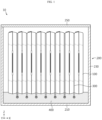
- FIG. 1 is a view for describing a battery module, according to an embodiment of the present disclosure.
- a battery module 10 includes a plurality of battery cells 100, a module housing 200, and a cooling fin 300.
- the plurality of battery cells 100 may be accommodated in the module housing 200.
- the plurality of battery cells 100 may be stacked to be electrically connected to each other in the module housing 200.
- Each of the plurality of battery cells 100 will be described in more detail.
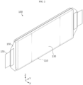
- FIG. 2 is a view for describing a battery cell of the battery module of FIG. 1 .
- the battery cell 100 may be a secondary battery, for example, a pouch-type battery cell 100.
- a type of the battery cell 100 is not limited thereto.
- another type of battery cell 100 such as a cylindrical cell or prismatic cell may also be employed in the battery module 10 of the present disclosure.
- the battery cell 100 is a pouch-type cell as shown in FIG. 2 .
- the battery cell 100 may include an electrode assembly 110, a receiving portion 130 in which the electrode assembly 110 is accommodated, a sealing portion 150 formed around the receiving portion 130, and a pair of electrode leads 170 connected to the electrode assembly 110 and drawn out to the outside of the sealing portion 150.
- the pair of electrode leads 170 may be coupled to electrode tabs (not shown) provided in the electrode assembly 110, and may be drawn out to the outside of the sealing portion 150 through the sealing portion 150.
- the pair of electrode leads 170 may extend in a longitudinal direction (Y axis direction) of the battery cell 100.
- the pair of electrode leads 170 may be drawn out in the same direction or opposite directions.
- the module housing 200 may have an inner space in which the plurality of battery cells 100 are accommodated.
- the module housing 200 may include a base plate 210, a side plate 230, and a cover plate 250.
- the plates may be coupled to each other by using a fastening method such as bolts or welding, or may be integrally manufactured.
- the module housing 200 may be formed of a material such as high-strength plastic, or may be formed of a metal material.
- the plurality of battery cells 100 may be accommodated in the module housing 200.
- the plurality of battery cells 100 may be vertically arranged on the base plate 210 so that portions of the sealing portion 150 parallel to the longitudinal direction (Y axis direction) of the battery cell 100 are located at an upper end and a lower end of the battery module 10.
- a plurality of battery cells 100 may be arranged in a thickness direction (X axis direction) of the battery cell 100.
- the battery module 10 may have a structure in which the battery cell 100 and the cooling fin 300 are alternately arranged.
- the cooling fin 300 may include an insulating cap 330 for preventing direct contact with the module housing 200.
- the insulating cap 330 will be described below in more detail.
- the cooling fin 300 according to the present disclosure will be described in more detail.
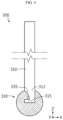
- FIG. 3 is a view for describing a cooling fin of the battery module of FIG. 1 .
- FIG. 4 is a cross-sectional view illustrating the cooling fin of FIG. 3 .
- the cooling fin 300 may include a fin body 310 and the insulating cap 330.
- the fin body 310 may be formed of a metal material with high thermal conductivity to smoothly cool the battery cell 100.
- the fin body 310 may be formed of a metal including aluminum, or may be formed of a metal including copper.
- the fin body 310 may surface-contact adjacent battery cells 100 between the plurality of battery cells 100. Accordingly, a widest surface of the battery cell 100 and the fin body 310 may surface-contact each other, and thus, cooling efficiency of the battery cell 100 may be further maximized.
- At least an end portion 312 of the fin body 310 may more protrude toward an inner surface 215 of the module housing 200 than the plurality of battery cells 100.
- the protruding end portion 312 of the fin body 310 may contact a heat sink (not shown), and may transfer heat received from the battery cell 100 to the heat sink through the end portion 312 of the fin body 310.
- the heat sink may transfer heat received from the fin body 310 to separate cooling water or air.
- a coupling end 315 having a loop shape may be provided on the at least an end portion 312 of the fin body 310. That is, the coupling end 315 provided on the at least an end portion 312 of the fin body 310 may have, for example, a loop shape. The at least an end portion 312 of the fin body 310 may be coupled to the insulating cap 330, through the coupling end 315 having a loop shape.
- the insulating cap 330 may prevent direct contact between the cooling fin 300 and the module housing 200.
- the insulating cap 330 may be formed in a direction (Y axis direction) parallel to a direction in which the electrode lead 170 extends.
- the insulating cap 330 may be coupled to the at least an end portion 312 of the fin body 310.
- the insulating cap 330 may have a structure surrounding the at least an end portion 312 of the fin body 310.
- a coupling hook 335 having a shape complementary to the loop shape of the coupling end 315 may be provided on the insulating cap 330 to facilitate coupling with the coupling end 315. That is, the coupling hook 335 of the insulating cap 330 may be engaged with the coupling end 315 provided on the end portion 312 of the fin body 310.
- the fin body 310 and the insulating cap 330 may be firmly coupled to each other only in a simple structure. Accordingly, even when the cooling fin 300 collides with the module housing 200 due to swelling of the battery cell 100 and/or external impact, coupling between the fin body 310 and the insulating cap 330 may be maintained.
- a method of coupling the fin body 310 to the insulating cap 330 is not limited to the above coupling method, and may be any method as long as the fin body 310 and the insulating cap 330 may be firmly and easily coupled to each other.
- the insulating cap 330 may be formed of an insulating material.
- the insulating cap 330 may be formed of a rubber material.
- the present disclosure is not limited thereto, and the insulating cap 330 may be formed of a material such as silicone or plastic or other insulating materials.
- the insulating cap 330 may be spaced apart from an inner surface of the module housing 200 by a certain distance, and may be located closer to the inner surface of the module housing 200 than the plurality of battery cells 100.
- the insulating cap 330 may be spaced apart from an inner surface 215 of the base plate 210 of the module housing 200 by a certain distance, and may be located closer to the inner surface 215 of the base plate 210 of the module housing 200 than the plurality of battery cells 100. That is, the insulating cap 330 may be located closer to the base plate 210 of the module housing 200, than the fin body 310 and the battery cell 100. Due to this structure, the fin body 310 or the battery cell 100 may be prevented from directly contacting the module housing 200.
- the present disclosure may not be limited to the structure of FIGS. 3 and 4 , and any structure is possible as long as the insulating cap 330 is located to prevent direct contact between the fin body 310 and the module housing 200.
- FIG. 5 is a view for describing a cooling fin, according to another embodiment of the present disclosure.
- FIG. 6 is an enlarged view illustrating an end portion of FIG. 5 .
- At least an end portion 362 of a fin body 360 of a cooling fin 350 may have an uneven shape in which at least one convex portion 363 and at least one concave portion 364 are alternately arranged in a direction parallel to the longitudinal direction (Y axis direction) of each battery cell 100.
- An insulating cap 380 may be coupled to the at least one convex portion 363.
- the fin body 360 has the uneven structure, a material of the fin body 360 required to manufacture the fin body 360 and the insulating cap 380 may be minimized, thereby reducing manufacturing costs.
- the risk of a short circuit between the cooling fin 350 and the module housing 200 may be minimized.
- the insulating cap 380 may have a structure surrounding the at least an end portion 362 of the fin body 360. Also, a coupling end 365 having a loop shape may be provided on the at least an end portion 362 of the fin body 360. The insulating cap 380 including a coupling hook 385 having a shape complementary to the loop shape of the coupling end 365 may be coupled to the coupling end 365.
- the battery module 10 may further include a heat dissipating resin 400.
- the heat dissipating resin 400 may be, for example, a thermally conductive adhesive with high thermal conductivity.
- the heat dissipating resin 400 may be coated to a certain height on the inner surface 215 of the base plate 210 of the module housing 200.
- the heat dissipating resin 400 may be provided in the module housing 200, and may contact the at least one cooling fin 300.
- the insulating cap 330 may be inserted into the heat dissipating resin 400.
- at least a part of the fin body 310 may be inserted into the heat dissipating resin 400.
- the cooling fin 300 may be more stably inserted and fixed to the heat dissipating resin 400. Accordingly, in the present embodiment, a fixing force of the cooling fin 300 may be improved without a separate additional fixing member through the heat dissipating resin 400. Also, due to the at least part of the fin body 310 inserted into the heat dissipating resin 400, heat transferred from the battery cell 100 may be easily transferred to the heat dissipating resin 400.
- each of the plurality of battery cells 100 may be inserted into the heat dissipating resin 400.
- the battery cell 100 may directly contact the heat dissipating resin 400. Accordingly, because heat generated in the battery cell 100 may be directly transferred to the heat dissipating resin 400 without passing through the cooling fin 300, cooling efficiency of the battery cell 100 may be further improved. Also, because the battery cell 100 may be inserted and fixed to the heat dissipating resin 400, a fixing force of the battery cell 100 may be improved without a separate additional fixing member.
- FIGS. 7 and 8 are views for describing a short circuit preventing mechanism through an insulating cap of a cooling fin in the battery module of FIG. 1 .
- the heat dissipating resin 400 is coated to a certain height on the inner surface 215 of the base plate 210 of the module housing 200 according to an embodiment of the present disclosure, and a plurality of battery cells 100 and a plurality of cooling fins 300 are vertically alternately arranged on the heat dissipating resin 400.
- the insulating cap 330 coupled to the end portion 312 of the fin body 310 may be spaced apart from the inner surface 215 of the base plate 210 of the module housing 200 by a certain distance, and may be located closer to the inner surface 215 of the base plate 210 of the module housing 200 than the plurality of battery cells 100.
- external impact may be applied to the cover plate 250 in a direction (-Z axis direction) perpendicular to the cover plate 250 of the module housing 200.
- the plurality of battery cells 100 and the plurality of cooling fins 300 accommodated in the module housing 200 may receive a force in a width direction (-Z axis direction) of the battery cell 100 and may be moved in the width direction (-Z axis direction) of the battery cell 100.
- the insulating cap 330 spaced apart from the inner surface 215 of the base plate 210 of the module housing 200 by a certain distance may first come into contact with the inner surface 215 of the base plate 210.
- each plate of the module housing 200 including the base plate 210 is formed of a metal material, due to the insulating cap 330, direct contact between the fin body 310 formed of a metal material and the base plate 210 formed of a metal material may be prevented, thereby preventing damage to the battery module 10 due to a short circuit.
- FIG. 9 is a view for describing a battery pack including the battery module of FIG. 1 .
- FIG. 10 is a view for describing a vehicle including the battery pack of FIG. 9 .
- a battery pack 1 according to the present disclosure may include at least one battery module 10 according to the present disclosure.
- the battery pack 1 according to the present disclosure may include a pack case 50 in which the at least one battery module 10 may be accommodated.
- various elements for example, a battery management system (BMS), a pack case, a relay, and a current sensor, which are known at the time of filling the present disclosure, in addition to the battery module 10 may be further included in the battery pack 1.
- BMS battery management system
- pack case a relay
- a current sensor which are known at the time of filling the present disclosure
- a vehicle V according to the present disclosure may include at least one battery pack 1 according to the present disclosure.
- the cooling fin 300 even when the cooling fin 300 comes into contact with the inner surface 215 of the module housing 200 due to swelling caused by abnormality of the battery cell 100 or external impact, a failure of the battery module 10 may be prevented through the insulating cap 330 capable of preventing direct contact with the module housing 200.
- the battery module 10 having improved insulation performance, and the battery pack 1 and the vehicle V including the battery module 10 may be provided.
Landscapes
- Chemical & Material Sciences (AREA)
- Chemical Kinetics & Catalysis (AREA)
- Electrochemistry (AREA)
- General Chemical & Material Sciences (AREA)
- Engineering & Computer Science (AREA)
- Manufacturing & Machinery (AREA)
- Aviation & Aerospace Engineering (AREA)
- Materials Engineering (AREA)
- Secondary Cells (AREA)
- Battery Mounting, Suspending (AREA)
Applications Claiming Priority (2)
| Application Number | Priority Date | Filing Date | Title |
|---|---|---|---|
| KR1020210093808A KR20230012930A (ko) | 2021-07-16 | 2021-07-16 | 배터리 모듈, 이러한 배터리 모듈을 포함하는 배터리 팩 및 이러한 배터리 팩을 포함하는 자동차 |
| PCT/KR2022/010391 WO2023287258A1 (fr) | 2021-07-16 | 2022-07-15 | Module de batterie, bloc-batterie comprenant un module de batterie et véhicule comprenant un bloc-batterie |
Publications (1)
| Publication Number | Publication Date |
|---|---|
| EP4287360A1 true EP4287360A1 (fr) | 2023-12-06 |
Family
ID=84919561
Family Applications (1)
| Application Number | Title | Priority Date | Filing Date |
|---|---|---|---|
| EP22842520.3A Pending EP4287360A1 (fr) | 2021-07-16 | 2022-07-15 | Module de batterie, bloc-batterie comprenant un module de batterie et véhicule comprenant un bloc-batterie |
Country Status (6)
| Country | Link |
|---|---|
| US (1) | US20230395895A1 (fr) |
| EP (1) | EP4287360A1 (fr) |
| JP (1) | JP2024501574A (fr) |
| KR (1) | KR20230012930A (fr) |
| CN (1) | CN116724445A (fr) |
| WO (1) | WO2023287258A1 (fr) |
Family Cites Families (6)
| Publication number | Priority date | Publication date | Assignee | Title |
|---|---|---|---|---|
| JP5433160B2 (ja) * | 2008-04-04 | 2014-03-05 | 株式会社Uacj | 電気化学デバイスユニットモジュール |
| KR102141209B1 (ko) | 2014-03-07 | 2020-08-05 | 삼성디스플레이 주식회사 | 디스플레이 장치 및 이의 제조 방법 |
| KR101637759B1 (ko) * | 2014-12-03 | 2016-07-07 | 현대자동차주식회사 | 배터리 셀 및 리드탭을 동시에 냉각하는 냉각플레이트 |
| JP2018060595A (ja) * | 2015-02-27 | 2018-04-12 | 三洋電機株式会社 | 電源装置及びこれを備える車両 |
| KR102173142B1 (ko) * | 2016-02-12 | 2020-11-02 | 주식회사 엘지화학 | 배터리 모듈 및 이를 포함하는 배터리 팩 |
| KR102184753B1 (ko) * | 2016-05-24 | 2020-11-30 | 주식회사 엘지화학 | 배터리 모듈, 이러한 배터리 모듈을 포함하는 배터리 팩 및 이러한 배터리 팩을 포함하는 자동차 |
-
2021
- 2021-07-16 KR KR1020210093808A patent/KR20230012930A/ko active Search and Examination
-
2022
- 2022-07-15 CN CN202280009661.3A patent/CN116724445A/zh active Pending
- 2022-07-15 US US18/267,766 patent/US20230395895A1/en active Pending
- 2022-07-15 WO PCT/KR2022/010391 patent/WO2023287258A1/fr active Application Filing
- 2022-07-15 JP JP2023540601A patent/JP2024501574A/ja active Pending
- 2022-07-15 EP EP22842520.3A patent/EP4287360A1/fr active Pending
Also Published As
| Publication number | Publication date |
|---|---|
| US20230395895A1 (en) | 2023-12-07 |
| KR20230012930A (ko) | 2023-01-26 |
| JP2024501574A (ja) | 2024-01-12 |
| WO2023287258A1 (fr) | 2023-01-19 |
| CN116724445A (zh) | 2023-09-08 |
Similar Documents
| Publication | Publication Date | Title |
|---|---|---|
| US11139515B2 (en) | Battery module having heat conduction pad | |
| CN110710051B (zh) | 电池组 | |
| EP2763214B1 (fr) | Module de batterie | |
| EP2983239B1 (fr) | Bloc-batterie de véhicule a efficacité de refroidissement améliorée | |
| KR101560217B1 (ko) | 냉각 효율이 향상된 전지모듈 | |
| US20220376337A1 (en) | Battery Module Having Plurality Of Cylindrical Battery Cells, Battery Pack Comprising Same, And Automobile | |
| KR101501026B1 (ko) | 우수한 냉각 효율성과 콤팩트한 구조의 전지모듈 | |
| US20190280258A1 (en) | Battery module having improved cooling performance | |
| KR102072765B1 (ko) | 배터리 모듈 및 이를 포함하는 배터리 팩, 자동차 | |
| EP3696905A1 (fr) | Module de batterie et bloc-batterie comprenant ledit module de batterie | |
| KR20170132514A (ko) | 배터리 모듈, 이러한 배터리 모듈을 포함하는 배터리 팩 및 이러한 배터리 팩을 포함하는 자동차 | |
| KR20200002349A (ko) | 단위체를 포함하는 배터리 모듈 | |
| CN112640193A (zh) | 包括盖结构的电池组、电子装置和车辆 | |
| CN116018714A (zh) | 电池模块及包括该电池模块的电池组 | |
| EP4012823A1 (fr) | Module de batterie, et bâti de batterie et dispositif de stockage d'énergie dotés chacun dudit module de batterie | |
| EP4287360A1 (fr) | Module de batterie, bloc-batterie comprenant un module de batterie et véhicule comprenant un bloc-batterie | |
| US11984612B2 (en) | Battery module comprising module housing | |
| EP3934009B1 (fr) | Module de batterie et bloc-batterie le comprenant | |
| EP4075573A1 (fr) | Module de batterie, et bloc-batterie et véhicule le comprenant | |
| EP3923403A1 (fr) | Connecteur, unité de gestion de batterie et bloc-batterie | |
| KR20230012931A (ko) | 배터리 모듈, 이러한 배터리 모듈을 포함하는 배터리 팩 및 이러한 배터리 팩을 포함하는 자동차 | |
| KR20210016826A (ko) | 냉각 부재를 구비한 배터리 모듈 및 배터리 팩 및 자동차 |
Legal Events
| Date | Code | Title | Description |
|---|---|---|---|
| STAA | Information on the status of an ep patent application or granted ep patent |
Free format text: STATUS: THE INTERNATIONAL PUBLICATION HAS BEEN MADE |
|
| PUAI | Public reference made under article 153(3) epc to a published international application that has entered the european phase |
Free format text: ORIGINAL CODE: 0009012 |
|
| STAA | Information on the status of an ep patent application or granted ep patent |
Free format text: STATUS: REQUEST FOR EXAMINATION WAS MADE |
|
| 17P | Request for examination filed |
Effective date: 20230831 |
|
| AK | Designated contracting states |
Kind code of ref document: A1 Designated state(s): AL AT BE BG CH CY CZ DE DK EE ES FI FR GB GR HR HU IE IS IT LI LT LU LV MC MK MT NL NO PL PT RO RS SE SI SK SM TR |