EP4286997A1 - Keyboard and electronic device - Google Patents
Keyboard and electronic device Download PDFInfo
- Publication number
- EP4286997A1 EP4286997A1 EP22847925.9A EP22847925A EP4286997A1 EP 4286997 A1 EP4286997 A1 EP 4286997A1 EP 22847925 A EP22847925 A EP 22847925A EP 4286997 A1 EP4286997 A1 EP 4286997A1
- Authority
- EP
- European Patent Office
- Prior art keywords
- metal frame
- keyboard
- inner metal
- component
- circuit board
- Prior art date
- Legal status (The legal status is an assumption and is not a legal conclusion. Google has not performed a legal analysis and makes no representation as to the accuracy of the status listed.)
- Granted
Links
Images





Classifications
-
- G—PHYSICS
- G06—COMPUTING OR CALCULATING; COUNTING
- G06F—ELECTRIC DIGITAL DATA PROCESSING
- G06F3/00—Input arrangements for transferring data to be processed into a form capable of being handled by the computer; Output arrangements for transferring data from processing unit to output unit, e.g. interface arrangements
- G06F3/01—Input arrangements or combined input and output arrangements for interaction between user and computer
- G06F3/02—Input arrangements using manually operated switches, e.g. using keyboards or dials
- G06F3/0202—Constructional details or processes of manufacture of the input device
-
- G—PHYSICS
- G06—COMPUTING OR CALCULATING; COUNTING
- G06F—ELECTRIC DIGITAL DATA PROCESSING
- G06F1/00—Details not covered by groups G06F3/00 - G06F13/00 and G06F21/00
- G06F1/16—Constructional details or arrangements
- G06F1/1613—Constructional details or arrangements for portable computers
- G06F1/1633—Constructional details or arrangements of portable computers not specific to the type of enclosures covered by groups G06F1/1615 - G06F1/1626
- G06F1/1662—Details related to the integrated keyboard
-
- G—PHYSICS
- G06—COMPUTING OR CALCULATING; COUNTING
- G06F—ELECTRIC DIGITAL DATA PROCESSING
- G06F1/00—Details not covered by groups G06F3/00 - G06F13/00 and G06F21/00
- G06F1/16—Constructional details or arrangements
- G06F1/1613—Constructional details or arrangements for portable computers
- G06F1/1633—Constructional details or arrangements of portable computers not specific to the type of enclosures covered by groups G06F1/1615 - G06F1/1626
- G06F1/1662—Details related to the integrated keyboard
- G06F1/1669—Detachable keyboards
-
- H—ELECTRICITY
- H01—ELECTRIC ELEMENTS
- H01H—ELECTRIC SWITCHES; RELAYS; SELECTORS; EMERGENCY PROTECTIVE DEVICES
- H01H13/00—Switches having rectilinearly-movable operating part or parts adapted for pushing or pulling in one direction only, e.g. push-button switch
- H01H13/70—Switches having rectilinearly-movable operating part or parts adapted for pushing or pulling in one direction only, e.g. push-button switch having a plurality of operating members associated with different sets of contacts, e.g. keyboard
- H01H13/86—Switches having rectilinearly-movable operating part or parts adapted for pushing or pulling in one direction only, e.g. push-button switch having a plurality of operating members associated with different sets of contacts, e.g. keyboard characterised by the casing, e.g. sealed casings or casings reducible in size
-
- H—ELECTRICITY
- H01—ELECTRIC ELEMENTS
- H01H—ELECTRIC SWITCHES; RELAYS; SELECTORS; EMERGENCY PROTECTIVE DEVICES
- H01H2209/00—Layers
- H01H2209/01—Increasing rigidity; Anti-creep
-
- H—ELECTRICITY
- H01—ELECTRIC ELEMENTS
- H01H—ELECTRIC SWITCHES; RELAYS; SELECTORS; EMERGENCY PROTECTIVE DEVICES
- H01H2219/00—Legends
- H01H2219/054—Optical elements
- H01H2219/062—Light conductor
-
- H—ELECTRICITY
- H01—ELECTRIC ELEMENTS
- H01H—ELECTRIC SWITCHES; RELAYS; SELECTORS; EMERGENCY PROTECTIVE DEVICES
- H01H2223/00—Casings
- H01H2223/008—Casings metallic
-
- H—ELECTRICITY
- H01—ELECTRIC ELEMENTS
- H01H—ELECTRIC SWITCHES; RELAYS; SELECTORS; EMERGENCY PROTECTIVE DEVICES
- H01H2227/00—Dimensions; Characteristics
- H01H2227/032—Operating force
-
- H—ELECTRICITY
- H01—ELECTRIC ELEMENTS
- H01H—ELECTRIC SWITCHES; RELAYS; SELECTORS; EMERGENCY PROTECTIVE DEVICES
- H01H2227/00—Dimensions; Characteristics
- H01H2227/036—Minimise height
-
- H—ELECTRICITY
- H01—ELECTRIC ELEMENTS
- H01H—ELECTRIC SWITCHES; RELAYS; SELECTORS; EMERGENCY PROTECTIVE DEVICES
- H01H2229/00—Manufacturing
- H01H2229/024—Packing between substrate and membrane
- H01H2229/028—Adhesive
Definitions
- Embodiments of this application relate to the field of terminal technologies, and in particular, to a keyboard and an electronic device.
- a user With explosive growth of electronic devices such as a portable laptop computer, a smartphone, and a tablet computer (portable equipment, PAD), the electronic devices have become important tools of daily work and entertainment.
- a user usually operates an electronic device by using a keyboard, to quickly perform an input or an output.
- the user has a stronger requirement for portability of the keyboard, but an overall thickness of the keyboard affects the portability of the keyboard.
- the keyboard In a use process of the keyboard, the keyboard needs to withstand an impact stress exerted by the user in a tapping process. To reduce a possibility that the keyboard sinks due to insufficient rigidity of the keyboard when the keyboard suffers from the impact stress in the use process, a strength enhancement mechanical part is disposed at the bottom of the keyboard, to improve a deformation resistance capability of the keyboard by using the strength enhancement mechanical part.
- the strength enhancement mechanical part added at the bottom increases the overall thickness of the keyboard. Consequently, the portability of the keyboard becomes poorer.
- Embodiments of this application provide a keyboard and an electronic device, so that an overall thickness of the keyboard can be reduced while it is ensured that rigidity of the keyboard meets a requirement, to improve portability of the keyboard.
- a first aspect of this application provides a keyboard, applied to an electronic device.
- the keyboard includes at least the following:
- the inner metal frame with a strength enhancement function is disposed between the outer metal frame and the keyboard assembly.
- the inner metal frame and the outer metal frame are connected, and the keyboard assembly and the inner metal frame are connected.
- Strength enhancement is performed on the keyboard by using the disposed inner metal frame, to improve a deformation resistance capability of the keyboard, and reduce a possibility that the keyboard deforms and sinks when the keyboard suffers from an impact stress in a use process. Therefore, a metal baseplate and a plastic frame of a current keyboard can be canceled, to help reduce an overall thickness of the keyboard while it is ensured that rigidity of the keyboard meets a requirement, and improve portability of the keyboard.
- the keyboard assembly is detachably connected to the inner metal frame.
- the keyboard assembly further includes a circuit board unit, the key is disposed on the circuit board unit, the circuit board unit is disposed on a side that is of the inner metal frame and that faces away from the outer metal frame, and the circuit board unit is detachably connected to the inner metal frame.
- the keyboard further includes an adaptation piece, and the circuit board unit is detachably connected to the inner metal frame by using the adaptation piece.
- the adaptation piece includes a first component and a second component, the first component is disposed on the inner metal frame, and the first component and the second component are fastened to connect the circuit board unit and the inner metal frame.
- the first component is threaded with the second component.
- the first component is a nut
- the inner metal frame includes a mounting hole
- the first component is inserted into the mounting hole
- the second component includes a bolt and a cap portion connected to the bolt
- the bolt is threaded with the first component
- the cap portion abuts against the circuit board unit to apply, to the circuit board unit, a pressure stress toward the inner metal frame.
- the circuit board unit includes a circuit board, a metal sheet, and a backlight module
- the circuit board is disposed on a side that is of the metal sheet and that faces the inner metal frame
- the backlight module is disposed on a side that is of the metal sheet and that faces away from the inner metal frame
- the circuit board includes a first avoidance hole
- the metal sheet includes a second avoidance hole
- the backlight module includes a third avoidance hole
- the first component is inserted into the first avoidance hole and the second avoidance hole
- the cap portion is accommodated in the third avoidance hole and abuts against a surface that is of the metal sheet and that faces away from the circuit board.
- the inner metal frame includes a transverse spacer and a longitudinal spacer, the transverse spacer and the longitudinal spacer are alternately disposed around the key avoidance hole, and the first component is disposed in an intersection region of the transverse spacer and the longitudinal spacer.
- the outer metal frame and the inner metal frame are detachably connected.
- the outer metal frame includes an outer surface and an inner surface, and the inner metal frame is stuck to the inner surface.
- the keyboard frame assembly further includes a first adhesive member disposed within the annular accommodation cavity, the key avoidance hole is located within a region limited by the annular accommodation cavity, and the first adhesive member connects the outer metal frame and the inner metal frame.
- the inner metal frame includes a transverse spacer and a longitudinal spacer, and the transverse spacer and the longitudinal spacer are alternately disposed around the key avoidance hole;
- a second aspect of the embodiments of this application provides an electronic device, including the keyboard according to the foregoing embodiment.
- the electronic device 1 may be a mobile terminal such as a desktop computer, a laptop computer (laptop), a tablet computer (Table), an ultra-mobile personal computer (ultra-mobile personal computer, UMPC), a handheld computer, a walkie-talkie, a netbook, a POS machine, or a personal digital assistant (personal digital assistant, PDA), a fixed terminal, or a foldable device.
- a mobile terminal such as a desktop computer, a laptop computer (laptop), a tablet computer (Table), an ultra-mobile personal computer (ultra-mobile personal computer, UMPC), a handheld computer, a walkie-talkie, a netbook, a POS machine, or a personal digital assistant (personal digital assistant, PDA), a fixed terminal, or a foldable device.
- FIG. 1 schematically shows a three-dimensional structure of an electronic device 1 according to an embodiment.
- the electronic device 1 may include a display 11 and a host body 12.
- the display 11 may be rotatably connected to the host body 12.
- the display 11 and the host body 12 may be connected by using a rotating shaft; or the display 11 and the host body 12 may be rotatably connected by using a hinge structure.
- the display 11 and the host body 12 may be mutually independent devices.
- the display 11 and the host body 12 are detachable. When being used, the display 11 is placed on the host body 12, and after the use, the display 11 and the host body 12 may be separated from each other.
- the display 11 is electrically connected to the host body 12.
- the display 11 may be electrically connected to the host body 12 by using a contact, or the display 11 is electrically connected to the host body 12 by using a flexible circuit board (Flexible Printed Circuit, FPC), or the display 11 is electrically connected to the host body 12 by using a wire.
- the display 11 may be wirelessly connected to the host body 12 by using a wireless signal.
- the electronic device 1 may further include a keyboard 2.
- the keyboard 2 may be disposed on the host body 12.
- the keyboard 2 is electrically connected to a control unit in the host body 12.
- the keyboard 2 serves as an input device of the electronic device 1.
- the keyboard 2 may be used to enter a character or an operation instruction by using a key, and may further control a cursor to move.
- the keyboard includes an outer metal frame, a plastic frame, a keyboard assembly, and a metal baseplate.
- the plastic frame is formed on the outer metal frame of the keyboard by using an injection molding process.
- the keyboard assembly is disposed between the outer metal frame and the metal baseplate. Both the keyboard assembly and the metal baseplate are attached to the plastic frame.
- the plastic frame carries the keyboard assembly and metal baseplate.
- a solder column protrudes from the plastic frame. The solder column penetrates through mounting holes of the keyboard assembly and the metal baseplate.
- the metal baseplate may serve as a strength enhancement structure, to improve overall rigidity of the keyboard, so as to resolve a problem that the outer metal frame sinks due to insufficient rigidity when the outer metal frame is pressed.
- the plastic frame and the metal baseplate lead to a large overall thickness of the keyboard. Consequently, portability of the keyboard is poor.
- an embodiment of this application provides a keyboard 2.
- An inner metal frame 42 is disposed between a keyboard assembly 3 and an outer metal frame 41, and the inner metal frame 42 carries the keyboard assembly 3.
- the inner metal frame 42 has a strength enhancement function, to improve overall rigidity of the keyboard 2. Therefore, a plastic frame and a metal baseplate in the keyboard can be canceled, to effectively reduce an overall thickness of the keyboard 2, reduce a weight of the keyboard 2, and help improve portability of the keyboard 2.
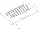
- FIG. 2 schematically shows a structure of a keyboard according to an embodiment of this application.
- a keyboard 2 in this embodiment of this application includes a keyboard assembly 3 and a keyboard frame assembly 4.
- the keyboard assembly 3 is connected to the keyboard frame assembly 4.
- the keyboard frame assembly 4 is configured to carry the keyboard assembly 3, or provide protection for the keyboard assembly 3 on an outer side of the keyboard assembly 3.
- the keyboard assembly 3 in this embodiment of this application includes a circuit board unit 31 and a plurality of keys 32 disposed on the circuit board unit 31.
- the circuit board unit 31 and the keys 32 are stacked in a thickness direction Z of the keyboard 2.
- the circuit board unit 31 may provide support for each key 32.
- the keys 32 include a numeric key, a function key (for example, a Delete key or an Insert key), and a letter key.
- the keys 32 may be classified into a single-unit key and a multi-unit key based on sizes of the keys.
- the single-unit key is a square key 32 on the keyboard 2, for example, a key 32 corresponding to each letter or each number.
- the multi-unit key is a key 32 other than the single-unit key, for example, a Space key, an Enter key, or a Shift key.
- the circuit board unit 31 includes a circuit board 311, a metal sheet 312, and a backlight module 313.
- the circuit board 311, the metal sheet 312, and the backlight module 313 are stacked in the thickness direction Z of the keyboard 2.
- the circuit board 311 is located on a side that is of the metal sheet 312 and on which the key 32 is disposed, and the backlight module 313 is located on a side that is of the metal sheet 312 and that faces away from the key 32.
- the metal sheet 312 can effectively improve a deformation resistance capability of the circuit board unit 31, to reduce a possibility that the circuit board 311 is broken when being bent or pulled.
- the circuit board 311 may be a flexible circuit board.
- a material of the metal sheet 312 may be steel, aluminum, or an aluminum alloy.
- the metal sheet 312 may be a steel sheet.
- a thickness of the metal sheet 312 is 0.3 millimeter to 0.4 millimeter.
- the key 32 includes a scissor leg assembly 321 and a keycap 322.
- the scissor leg assembly 321 is separately rotatably connected to the keycap 322 and the metal sheet 312.
- the scissor leg assembly 321 is disposed below the keycap 322.
- the scissor leg assembly 321 is configured to provide good support for the keycap 322, so that a pressure stress exerted on the keycap 322 can be balanced, and a user can press the keycap 322 at any location on the keycap 322 by exerting fixed pressure, to reduce a possibility that the keycap 322 withstands uneven pressure or a key is stuck.
- one or more scissor leg assemblies 321 may be disposed below one keycap 322.
- the scissor leg assembly 321 includes an outer scissor leg 321a and an inner scissor leg 321b.
- the outer scissor leg 321a and the inner scissor leg 321b intersect with each other and are rotatably connected. Respective lower ends of the outer scissor leg 321a and the inner scissor leg 321b are rotatably connected to the metal sheet 312. Respective upper ends of the outer scissor leg 321a and the inner scissor leg 321b are rotatably connected to the keycap 322.
- the outer scissor leg 321a and the inner scissor leg 321b each may be of a box structure.
- the backlight module 313 may be configured to provide backlight for the key 32, so that in an environment with dark light, the user can clearly observe a corresponding key 32, to reduce a possibility that the key 32 is wrongly operated, and improve input accuracy and input efficiency.
- the backlight module 313 includes a light guide board (not shown in the figure) and a light-emitting unit (not shown in the figure).
- the light guide board has light guiding and light uniformization functions.
- the backlight module 313 may display the backlight by using the light guide board, to illuminate the key 32 in a corresponding region.
- the light emitting unit is configured to emit light into the light guide board.
- the light emitting unit may be disposed at a location near an edge of the light guide board. After being lit, the light emitting unit emits light into the light guide board. After the light is uniformized by the light guide board, a region of the 32 keys is illuminated.
- the light emitting unit may be an LED lamp.
- the circuit board unit 31 and the key 32 of the keyboard assembly 3 may be assembled to form a whole, and then are assembled with the keyboard frame assembly 4 to form the keyboard 2.
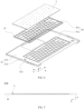
- FIG. 4 schematically shows a partial exploded structure of a keyboard 2 according to an embodiment of this application.
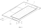
- FIG. 5 schematically shows a rear-side structure of a keyboard 2 according to an embodiment of this application.
- the keyboard frame assembly 4 in this embodiment of this application includes an outer metal frame 41, an inner metal frame 42, and a key avoidance hole 43.
- the inner metal frame 42 is connected to the outer metal frame 41.
- the key avoidance hole 43 penetrates through the outer metal frame 41 and the inner metal frame 42.
- the keyboard assembly 3 is connected to the inner metal frame 42.
- the inner metal frame 42 is located between the outer metal frame 41 and the keyboard assembly 3.
- the inner metal frame 42 is configured to carry the keyboard assembly 3.
- the key 32 is disposed in correspondence with the key avoidance hole 43, so that the key 32 may be exposed from the key avoidance hole 43, and the user taps the key 32 to execute an input instruction.
- the outer metal frame 41 may be of an integral structure, to help improve rigidity and a deformation resistance capability of the outer metal frame 41 while it is ensured that the outer metal frame 41 is lightweighted.
- the outer metal frame 41 may be processed and manufactured in a processing manner such as stamping, die casting, or model casting.
- a material of the outer metal frame 41 may be aluminum, an aluminum alloy, or steel.
- the outer metal frame 41 is provided with a first opening 41a used to avoid the key 32.
- the key avoidance hole 43 includes the first opening 41a.
- the outer metal frame 41 includes an outer surface 41b and an inner surface 41c that are opposite to each other. The first opening 41a penetrates through the outer surface 41b and the inner surface 41c.
- the outer surface 41b of the outer metal frame 41 is a surface that is of the outer metal frame 41 and that faces the user when the user uses the keyboard 2.
- the inner surface 41c of the outer metal frame 41 is a surface that is of the outer metal frame 41 and that faces an inside of the keyboard 2 when the user uses the keyboard 2. In this case, the user cannot easily observe the inner surface 41c of the outer metal frame 41 from an outside of the keyboard 2.
- the inner metal frame 42 is disposed on an inner side of the outer metal frame 41.
- the inner metal frame 42 may be connected to the inner surface 41c of the outer metal frame 41.
- the inner metal frame 42 may perform strength enhancement on the outer metal frame 41, to help reduce a possibility that the outer metal frame 41 sinks under pressure.
- the inner metal frame 42 may be of an integral structure, to help improve rigidity and a deformation resistance capability of the inner metal frame 42 while it is ensured that the inner metal frame 42 is lightweighted.
- the inner metal frame 42 may be processed and manufactured in a processing manner such as stamping, die casting, or model casting.
- the inner metal frame 42 may be formed by stamping a flat plate.
- a material of the inner metal frame 42 may be aluminum, an aluminum alloy, or steel.
- the inner metal frame 42 is provided with a second opening 42a used to avoid the key 32.
- the key avoidance hole 43 includes the second opening 42a.
- the first opening 41a and the second opening 42a are aligned and communicate to form the key
- FIG. 6 schematically shows a partial exploded structure of a keyboard according to an embodiment of this application.
- the outer metal frame 41 includes a first board 411 and a first side plate 412.
- the first board 411 and the first side plate 412 intersect to form an accommodation concave part 41d.
- the first opening 41a is disposed on the first board 411.
- a heat dissipation hole may be disposed on the first side plate 412.
- the inner metal frame 42 is located in the accommodation concave part 41d. In the thickness direction Z of the keyboard 2, the inner metal frame 42 and the first board 411 are stacked and connected to the first board 411.
- the keyboard assembly 3 is connected to the inner metal frame 42, so that the inner metal frame 42 can carry the keyboard assembly 3.
- the keyboard assembly 3 is suspended below the inner metal frame 42.
- the keyboard assembly 3 applies, to the inner metal frame 42, a tensile stress that is away from the outer metal frame 41, and the inner metal frame 42 applies, to the outer metal frame 41, a tensile stress that faces away from the inner surface 41c of the outer metal frame 41.
- the inner metal frame 42 and the outer metal frame 41 are combined with each other, and the inner metal frame 42 has high rigidity and has a strength enhancement function. Therefore, when an external force is exerted on the keyboard assembly 3, the keyboard assembly 3 does not easily deform or sink, and the keyboard assembly 3 does not easily pull the inner metal frame 42 and the outer metal frame 41 to deform or sink.
- the inner metal frame 42 with the strength enhancement function is disposed between the outer metal frame 41 and the keyboard assembly 3.
- the inner metal frame 42 is connected to the outer metal frame 41, and the keyboard assembly 3 is connected to the inner metal frame 42.
- Strength enhancement is performed on the keyboard 2 by using the disposed inner metal frame 42, to improve a deformation resistance capability of the keyboard 2, and reduce a possibility that the keyboard 2 deforms and sinks when the keyboard 2 suffers from an impact stress in a use process. Therefore, a metal baseplate and a plastic frame of a current keyboard can be canceled, to help reduce an overall thickness of the keyboard 2 while it is ensured that rigidity of the keyboard 2 meets a requirement, and improve portability of the keyboard 2.
- a solder column protrudes from the plastic frame.
- An end portion that is of the solder column and that penetrates through the metal baseplate deforms through hot melting or pressing, and is clamped on a bottom surface of the metal baseplate, to connect the keyboard assembly, the metal baseplate, and the plastic frame.
- the keyboard assembly and the plastic frame can be separated only after the end portion of the solder column is cut off. Consequently, the plastic frame cannot be reused.
- the plastic frame and the outer metal frame are both scrapped.
- the keyboard assembly 3 is detachably connected to the inner metal frame 42, so that the keyboard assembly 3 can be removed from the inner metal frame 42 when the keyboard assembly 3 needs to be repaired.
- the keyboard assembly 3 is reinstalled on the inner metal frame 42, so that the inner metal frame 42 and the outer metal frame 41 can be reused, thereby reducing maintenance difficulty and maintenance costs.
- the keyboard assembly 3 and the inner metal frame 42 may be stuck by using an adhesive member.
- the keyboard assembly 3 and the inner metal frame 42 may be snap-fitted by using a snap-fit.
- the keyboard assembly 3 and the inner metal frame 42 may be fastened by using a fastener.
- the fastener may be a screw.
- the keyboard assembly 3 includes the circuit board unit 31.
- the key 32 is disposed on the circuit board unit 31.
- the circuit board unit 31 provides support for the key 32.
- the circuit board unit 31 is disposed on a side that is of the inner metal frame 42 and that faces away from the outer metal frame 41.
- the circuit board unit 31 is detachably connected to the inner metal frame 42.
- the circuit board unit 31 is of a plate-like structure and has high rigidity. Therefore, the circuit board unit 31 is connected to the inner metal frame 42, to effectively ensure stability and reliability of a connection between the circuit board unit 31 and the inner metal frame 42, and reduce a possibility that the keyboard assembly 3 and the inner metal frame 42 are loosened or separated due to frequent tapping.
- the circuit board unit 31 includes the circuit board 311, the metal sheet 312, and the backlight module 313.
- the circuit board 311 is disposed on a side that is of the metal sheet 312 and that faces the inner metal frame 42.
- the circuit board 311 may be a printed circuit board (Printed Circuit Board, PCB) or a flexible circuit board.
- the backlight module 313 is disposed on a side that is of the metal sheet 312 and that faces away from the inner metal frame 42.
- the circuit board 311 has signal collection and signal processing functions. When the key 32 is tapped, a corresponding region of the circuit board 311 is triggered to execute a corresponding input instruction.
- the metal sheet 312 of the circuit board unit 31 is detachably connected to the inner metal frame 42. Light of the backlight module 313 may penetrate through the metal sheet 312 and the circuit board 311 and illuminate the key 32.
- the keyboard 2 in this embodiment of this application further includes an adaptation piece 5.
- the circuit board unit 31 is detachably connected to the inner metal frame 42 by using the adaptation piece 5.
- a part of the adaptation piece 5 is connected to the circuit board unit 31, and the other part is connected to the inner metal frame 42, so that the circuit board unit 31 is pressed against a surface that is of the inner metal frame 42 and that faces the circuit board unit 31.
- the adaptation piece 5 may be removed to separate the keyboard assembly 3 and the inner metal frame 42.
- the adaptation piece 5 includes a first component 51 and a second component 52.
- the first component 51 and the second component 52 are independently disposed. After the first component 51 and the second component 52 are separately processed and manufactured, the first component 51 and the second component 52 may be connected to each other to form the adaptation piece 5.
- the first component 51 is disposed on the inner metal frame 42.
- the first component 51 may be detachably connected to the inner metal frame 42. After the inner metal frame 42 and the outer metal frame 41 are assembled, the first component 51 is connected to the inner metal frame 42. Alternatively, the first component 51 is connected to the inner metal frame 42 in advance, and then the inner metal frame 42 with the first component 51 is connected to the outer metal frame 41.
- the first component 51 may be directly built into or soldered onto the inner metal frame 42 to form an integral structure with the inner metal frame 42.
- the first component 51 is built into or soldered onto the inner metal frame 42, and then the inner metal frame 42 is connected to the outer metal frame 41. Therefore, in a process of connecting the inner metal frame 42 and the outer metal frame 41, the first component 51 is not easily separated from the inner metal frame 42 and lost.
- the keyboard assembly 3 and the inner metal frame 42 are connected by using the second component 52 and the first component 51.
- the first component 51 and the second component 52 are fastened to connect the circuit board unit 31 and the inner metal frame 42.
- the first component 51 and the second component 52 that are separately designed are used for the adaptation piece 5, so that the first component 51 is positioned and mounted on the inner metal frame 42 in advance, and then the keyboard assembly 3 is fastened by using the second component 52. Therefore, the second component 52 may be directly aligned with the first component 51 to perform a connection operation, and the second component 52 does not need to be repositioned with respect to the inner metal frame 42.
- the first component 51 is threaded with the second component 52.
- One of the first component 51 and the second component 52 has an external thread, and the other has an internal thread.
- the threads may guide the second component 52 to be aligned with the first component 51, to reduce difficulty in positioning the first component 51 and the second component 52 in alignment with each other, and help improve connection convenience and connection efficiency.
- the first component 51 and the second component 52 are easily self-locked, and have good anti-loosening performance and connection stability, to reduce a probability that a gap occurs between the keyboard assembly 3 and the inner metal frame 42 after the first component 51 and the second component 52 are mutually loosened after long-term use, and the keyboard assembly 3 becomes loose, affecting stability and comfort of tapping the key 32 by the user.
- the first component 51 is a nut.
- the inner metal frame 42 includes a mounting hole.
- the first component 51 is inserted into the mounting hole.
- the first component 51 may be partially located in the mounting hole, and partially located outside the mounting hole, or may be integrally located in the mounting hole.
- the first component 51 is pressed into the mounting hole of the inner metal frame 42 in an extrusion manner. Referring to FIG. 9 and FIG.
- a tooth portion 511 may be disposed on a peripheral surface of the first component 51, so that after the first component 51 is pressed into the mounting hole, the tooth portion 511 of the first component 51 may be built into a hole wall of the mounting hole, to improve a bonding force and connection stability between the first component 51 and the inner metal frame 42, reduce a possibility that the first component 51 easily drops from the inner metal frame 42, and further reduce a possibility that the first component 51 rotates in the mounting hole when the first component 51 withstands torque.
- a plurality of tooth portions 511 are evenly distributed in an annular shape around the first component 51.
- the second component 52 includes a bolt 521 and a cap portion 522 connected to the bolt 521. The bolt 521 is threaded with the first component 51.
- the bolt 521 has an external thread
- the first component 51 has an internal threaded hole that matches the external thread.
- the cap portion 522 of the second component 52 abuts against the circuit board unit 31, to apply, to the circuit board unit 31, a pressure stress toward the inner metal frame 42.
- the cap portion 522 of the second component 52 may carry the keyboard assembly 3, and also limit the keyboard assembly 3, to reduce a possibility that the keyboard assembly 3 moves away from the inner metal frame 42.
- the circuit board unit 31 includes the circuit board 311, the metal sheet 312, and the backlight module 313.
- the circuit board 311 includes a first avoidance hole 311a.
- the metal sheet 312 includes a second avoidance hole 312a.
- the backlight module 313 includes a third avoidance hole 313a.
- the first avoidance hole 311a, the second avoidance hole 312a, and the third avoidance hole 313a are aligned, and communicate with each other.
- the first component 51 is inserted into the first avoidance hole 311a and the second avoidance hole 312a, so that the circuit board unit 31 may be positioned by using the first component 51, to quickly and accurately adjust relative locations of the circuit board unit 31 and the inner metal frame 42.
- the cap portion 522 of the second component 52 is accommodated in the third avoidance hole 313a and abuts against a surface that is of the metal sheet 312 and that faces away from the circuit board 311.
- the metal sheet 312 has high rigidity. Therefore, when the second component 52 abuts against the metal sheet 312, and a large pressure stress may be applied to the metal sheet 312, to improve connection stability between the circuit board unit 31 and the inner metal frame 42.
- the second component 52 and the metal sheet 312 each are of a metal material. Therefore, after the cap portion 522 of the second component 52 abuts against the metal sheet 312, the cap portion 522 is not easily rotated and loosened relative to the metal sheet 312.
- the cap portion 522 of the second component 52 is accommodated in the third avoidance hole 313a. Space of the third avoidance hole 313a may be used, to help reduce the overall thickness of the keyboard 2.
- the backlight module 313 may be avoided, to reduce a possibility that a structure of the backlight module 313 is damaged because the cap portion 522 of the second component 52 abuts against the backlight module 313.
- the cap portion 522 of the second component 52 is integrally located in the third avoidance hole 313a.
- a top surface that is of the cap portion 522 of the second component 52 and that faces away from the inner metal frame 42 is flush with an edge of the third avoidance hole 313a formed in the backlight module 313, or a top surface that is of the cap portion 522 of the second component 52 and that faces away from the inner metal frame 42 is lower than an edge of the third avoidance hole 313a formed in the backlight module 313, to reduce a possibility that the cap portion 522 of the second component 52 collides with or scratches an adjacent mechanical part.
- the inner metal frame 42 includes a transverse spacer 421 and a longitudinal spacer 422 that are connected to each other.
- the entire keyboard 2 has a length and a width.
- the transverse spacer 421 extends in a length direction X of the keyboard 2.
- the longitudinal spacer 422 extends in a width direction Y of the keyboard 2.
- the transverse spacer 421 and the longitudinal spacer 422 are alternately disposed around the key avoidance hole 43.
- two longitudinal spacers 422 are disposed on a left side and a right side of each key avoidance hole 43, and two transverse spacers 421 are disposed on an upper side and a lower side.
- a plurality of transverse spacers 421 and a plurality of longitudinal spacers 422 are classified to form a plurality of second openings 42a.
- the first component 51 is disposed in an intersection region of the transverse spacer 421 and the longitudinal spacer 422.
- the intersection region of the transverse spacer 421 and the longitudinal spacer 422 has a large area, and therefore, has high rigidity.
- an acting force is transmitted to the inner metal frame 42 through the first component 51.
- the intersection region of the transverse spacer 421 and the longitudinal spacer 422 has high rigidity, and has a strong deformation resistance capability. Therefore, under a pulling action of the first component 51, the intersection region of the transverse spacer 421 and the longitudinal spacer 422 does not easily deform or sink, to ensure that the keyboard 2 can still remain structurally stable when withstanding impact.
- the transverse spacer 421 and the longitudinal spacer 422 are disposed on the second board 423.
- the outer metal frame 41 and the inner metal frame 42 are detachably connected.
- the outer metal frame 41 and the inner metal frame 42 each are independently processed and manufactured, and then are assembled.
- the outer metal frame 41 or the inner metal frame 42 is repaired subsequently, the outer metal frame 41 and the inner metal frame 42 are separated.
- the outer metal frame 41 and the inner metal frame 42 are recombined, so that both the outer metal frame 41 and the inner metal frame 42 can be reused, to reduce maintenance difficulty and maintenance costs.
- the outer metal frame 41 includes an outer surface 41b and an inner surface 41c that are opposite in a thickness direction of the outer metal frame 41.
- the inner metal frame 42 is stuck to the inner surface 41c.
- a predetermined location of the outer metal frame 41 or a predetermined location of the inner metal frame 42 is coated with glue or an adhesive tape in advance, and then the inner metal frame 42 and the outer metal frame 41 are stuck and fastened.
- a connection structure may not need to be additionally disposed on the outer metal frame 41 or the inner metal frame 42 to connect and fasten the outer metal frame 41 and the inner metal frame 42, to reduce structural complexity of the outer metal frame 41 or the inner metal frame 42, and reduce processing difficulty of the outer metal frame 41 or the inner metal frame 42.
- a quantity of parts used for the keyboard 2 is reduced, to help reduce an assembly process and assembly difficulty of the keyboard 2.
- a glue coating thickness or a thickness of the adhesive tape is precisely controlled, to help further reduce the overall thickness of the keyboard 2.
- the keyboard frame assembly 4 further includes a first adhesive member 6 disposed in the annular accommodation cavity.
- the first adhesive member 6 is an adhesive tape or cured glue.
- the key avoidance hole 43 is located in a region limited by the annular accommodation cavity.
- the first adhesive member 6 connects the outer metal frame 41 and the inner metal frame 42. Before the outer metal frame 41 and the inner metal frame 42 are assembled, the predetermined location of the outer metal frame 41 or the predetermined location of the inner metal frame 42 is coated with the glue or the adhesive tape in advance, and then the outer metal frame 41 and the inner metal frame 42 are stuck together.
- the glue or the adhesive tape is located in the annular accommodation cavity.
- the annular accommodation cavity may limit the glue or the adhesive tape, to reduce a possibility that the glue spills from space between the outer metal frame 41 and the inner metal frame 42 or that the adhesive tape is misaligned.
- the annular accommodation cavity is a continuously extending cavity.
- An annular groove 42b is disposed in an edge region of the inner metal frame 42, so that after the outer metal frame 41 and the inner metal frame 42 are combined, the annular groove 42b and the inner surface 41c of the outer metal frame 41 form the annular accommodation cavity.
- the second opening 42a of the inner metal frame 42 is located in a region limited by the annular groove 42b.
- the inner metal frame 42 includes the second board 423, a second side plate 424, and a flange 425.
- the second side plate 424 and the second board 423 intersect.
- the flange 425 and the second side plate 424 are connected.
- the second board 423 includes the transverse spacer 421, the longitudinal spacer 422, and the second opening 42a formed through division of the transverse spacer 421 and the longitudinal spacer 422.
- the annular groove 42b is disposed on a surface that is of the flange 425 and that faces the outer metal frame 41.
- the keyboard frame assembly 4 further includes a second adhesive member 7 disposed in the first chamber.
- the second adhesive member 7 is an adhesive tape or cured glue.
- the second adhesive member 7 connects the outer metal frame 41 and the inner metal frame 42.
- the predetermined location of the outer metal frame 41 or the predetermined location of the inner metal frame 42 is coated with the glue or the adhesive tape in advance, and then the outer metal frame 41 and the inner metal frame 42 are stuck together.
- the glue or the adhesive tape is located in the first chamber.
- the first chamber may limit the glue or the adhesive tape, to reduce the possibility that the glue spills from space between the outer metal frame 41 and the inner metal frame 42 or that the adhesive tape is misaligned.
- FIG. 11 and FIG. 12 each schematically show a partial structure of a keyboard 2 according to an embodiment of this application.
- a first concave part 421a is disposed on the transverse spacer 421 of the inner metal frame 42, so that after the outer metal frame 41 and the inner metal frame 42 are combined, the first concave part 421a and the inner surface 41c of the outer metal frame 41 form the first chamber.
- first concave part 421a is coated with glue or an adhesive tape in advance.
- the first adhesive member 6 and the second adhesive member 7 jointly connect the outer metal frame 41 and the inner metal frame 42, to help further improve connection strength of the outer metal frame 41 and the inner metal frame 42.
- the keyboard frame assembly 4 further includes a second adhesive member 7 disposed in the second chamber.
- the predetermined location of the outer metal frame 41 or the predetermined location of the inner metal frame 42 is coated with the glue or the adhesive tape in advance, and then the outer metal frame 41 and the inner metal frame 42 are stuck together.
- the glue or the adhesive tape is located in the second chamber.
- the second chamber may limit the glue or the adhesive tape, to reduce the possibility that the glue spills from space between the outer metal frame 41 and the inner metal frame 42 or that the adhesive tape is misaligned. For example, referring to FIG.
- a second concave part 422a is disposed on the longitudinal spacer 422 of the inner metal frame 42, so that after the outer metal frame 41 and the inner metal frame 42 are combined, the second concave part 422a and the inner surface 41c of the outer metal frame 41 form the second chamber.
- an inside of the second concave part 422a is coated with glue or an adhesive tape in advance.
- the keyboard frame assembly 4 further includes a second adhesive member 7 disposed in the first chamber and the second chamber.
- the first chamber and the second chamber may communicate.
- the first component 51 may be disposed at an intersection of the first chamber and the second chamber, and an end surface that is of the first component 51 and that faces the outer metal frame 41 is exposed from the inner metal frame 42, so that glue or an adhesive tape can connect the first component 51 and the outer metal frame 41.
- a part that is of the outer metal frame 41 and that corresponds to the first component 51 may exert an opposite acting force on the first component 51, to further reduce a possibility that the first component 51 and the inner metal frame 42 move away from the outer metal frame 41.
- An embodiment of this application provides a method for manufacturing a keyboard 2, including:
- the keyboard 2 in the foregoing embodiment may be manufactured.
- mount shall be understood in a broad sense, for example, may be a fixed connection, may be an indirect connection by using an intermediate medium, or may be a connection between insides of two elements or an interaction relationship between two elements.
- connect shall be understood in a broad sense, for example, may be a fixed connection, may be an indirect connection by using an intermediate medium, or may be a connection between insides of two elements or an interaction relationship between two elements.
- a process, a method, a system, a product, or a device that includes a series of steps or units is not necessarily limited to those steps or units that are clearly listed, but may include other steps or units that are not clearly listed or are inherent to the process, method, product, or device.
- a plurality of in this specification indicates two or more.
- the term “and/or” in this specification describes only an association relationship between associated objects and represents that three relationships can exist. For example, “A and/or B” can represent the following three cases: Only A exists, both A and B exist, and only B exists.
- the character “/” in this specification usually indicates an "or” relationship between the associated objects. In a formula, the character "/" indicates that the associated objects are in a "division" relationship.
- sequence numbers of the foregoing processes do not mean execution sequences.
- the execution sequences of the processes should be determined based on functions and internal logic of the processes, and should not be construed as any limitation on the implementation processes of the embodiments of this application.
Landscapes
- Engineering & Computer Science (AREA)
- Theoretical Computer Science (AREA)
- General Engineering & Computer Science (AREA)
- Human Computer Interaction (AREA)
- Physics & Mathematics (AREA)
- General Physics & Mathematics (AREA)
- Computer Hardware Design (AREA)
- Input From Keyboards Or The Like (AREA)
Abstract
Description
- This application claims priority to
Chinese Patent Application No. 202110867785.2, entitled "KEYBOARD AND ELECTRONIC DEVICE" filed with the China National Intellectual Property Administration on July 29, 2021 - Embodiments of this application relate to the field of terminal technologies, and in particular, to a keyboard and an electronic device.
- With explosive growth of electronic devices such as a portable laptop computer, a smartphone, and a tablet computer (portable equipment, PAD), the electronic devices have become important tools of daily work and entertainment. A user usually operates an electronic device by using a keyboard, to quickly perform an input or an output. The user has a stronger requirement for portability of the keyboard, but an overall thickness of the keyboard affects the portability of the keyboard.
- In a use process of the keyboard, the keyboard needs to withstand an impact stress exerted by the user in a tapping process. To reduce a possibility that the keyboard sinks due to insufficient rigidity of the keyboard when the keyboard suffers from the impact stress in the use process, a strength enhancement mechanical part is disposed at the bottom of the keyboard, to improve a deformation resistance capability of the keyboard by using the strength enhancement mechanical part. However, the strength enhancement mechanical part added at the bottom increases the overall thickness of the keyboard. Consequently, the portability of the keyboard becomes poorer.
- Embodiments of this application provide a keyboard and an electronic device, so that an overall thickness of the keyboard can be reduced while it is ensured that rigidity of the keyboard meets a requirement, to improve portability of the keyboard.
- A first aspect of this application provides a keyboard, applied to an electronic device. The keyboard includes at least the following:
- a keyboard assembly, including a key; and
- a keyboard frame assembly, including an outer metal frame, an inner metal frame, and a key avoidance hole, where the inner metal frame is connected to the outer metal frame, the key avoidance hole penetrates through the outer metal frame and the inner metal frame, the keyboard assembly is connected to the inner metal frame, the inner metal frame is located between the outer metal frame and the keyboard assembly, the inner metal frame is configured to carry the keyboard assembly, and the key is disposed in correspondence with the key avoidance hole.
- According to the keyboard provided in this embodiment of this application, the inner metal frame with a strength enhancement function is disposed between the outer metal frame and the keyboard assembly. The inner metal frame and the outer metal frame are connected, and the keyboard assembly and the inner metal frame are connected. Strength enhancement is performed on the keyboard by using the disposed inner metal frame, to improve a deformation resistance capability of the keyboard, and reduce a possibility that the keyboard deforms and sinks when the keyboard suffers from an impact stress in a use process. Therefore, a metal baseplate and a plastic frame of a current keyboard can be canceled, to help reduce an overall thickness of the keyboard while it is ensured that rigidity of the keyboard meets a requirement, and improve portability of the keyboard.
- In a possible implementation, the keyboard assembly is detachably connected to the inner metal frame.
- In a possible implementation, the keyboard assembly further includes a circuit board unit, the key is disposed on the circuit board unit, the circuit board unit is disposed on a side that is of the inner metal frame and that faces away from the outer metal frame, and the circuit board unit is detachably connected to the inner metal frame.
- In a possible implementation, the keyboard further includes an adaptation piece, and the circuit board unit is detachably connected to the inner metal frame by using the adaptation piece.
- In a possible implementation, the adaptation piece includes a first component and a second component, the first component is disposed on the inner metal frame, and the first component and the second component are fastened to connect the circuit board unit and the inner metal frame.
- In a possible implementation, the first component is threaded with the second component.
- In a possible implementation, the first component is a nut, the inner metal frame includes a mounting hole, the first component is inserted into the mounting hole, the second component includes a bolt and a cap portion connected to the bolt, the bolt is threaded with the first component, and the cap portion abuts against the circuit board unit to apply, to the circuit board unit, a pressure stress toward the inner metal frame.
- In a possible implementation, the circuit board unit includes a circuit board, a metal sheet, and a backlight module, the circuit board is disposed on a side that is of the metal sheet and that faces the inner metal frame, the backlight module is disposed on a side that is of the metal sheet and that faces away from the inner metal frame, the circuit board includes a first avoidance hole, the metal sheet includes a second avoidance hole, the backlight module includes a third avoidance hole, the first component is inserted into the first avoidance hole and the second avoidance hole, and the cap portion is accommodated in the third avoidance hole and abuts against a surface that is of the metal sheet and that faces away from the circuit board.
- In a possible implementation, the inner metal frame includes a transverse spacer and a longitudinal spacer, the transverse spacer and the longitudinal spacer are alternately disposed around the key avoidance hole, and the first component is disposed in an intersection region of the transverse spacer and the longitudinal spacer.
- In a possible implementation, the outer metal frame and the inner metal frame are detachably connected.
- In a possible implementation, the outer metal frame includes an outer surface and an inner surface, and the inner metal frame is stuck to the inner surface.
- In a possible implementation, there is an annular accommodation cavity between the inner metal frame and the inner surface, the keyboard frame assembly further includes a first adhesive member disposed within the annular accommodation cavity, the key avoidance hole is located within a region limited by the annular accommodation cavity, and the first adhesive member connects the outer metal frame and the inner metal frame.
- In a possible implementation, the inner metal frame includes a transverse spacer and a longitudinal spacer, and the transverse spacer and the longitudinal spacer are alternately disposed around the key avoidance hole;
- there is a first chamber between the transverse spacer and the inner surface, and the keyboard frame assembly further includes a second adhesive member disposed in the first chamber; or
- there is a second chamber between the longitudinal spacer and the inner surface, and the keyboard frame assembly further includes a second adhesive member disposed in the second chamber; or
- there is a first chamber between the transverse spacer and the inner surface, there is a second chamber between the longitudinal spacer and the inner surface, and the keyboard frame assembly further includes a second adhesive member disposed in the first chamber and the second chamber; and
- the second adhesive member connects the outer metal frame and the inner metal frame.
- A second aspect of the embodiments of this application provides an electronic device, including the keyboard according to the foregoing embodiment.
-
-
FIG. 1 is a schematic diagram of a structure of an electronic device according to an embodiment of this application; -
FIG. 2 is a schematic diagram of a structure of a keyboard according to an embodiment of this application; -
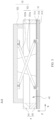
FIG. 3 is a schematic diagram of a cross-sectional structure in an A-A direction inFIG. 2 ; -
FIG. 4 is a schematic diagram of a partial exploded structure of a keyboard according to an embodiment of this application; -
FIG. 5 is a schematic diagram of a rear-side structure of a keyboard according to an embodiment of this application; -
FIG. 6 is a schematic diagram of a partial exploded structure of a keyboard according to another embodiment of this application; -
FIG. 7 is a schematic diagram of a cross-sectional structure in a B-B direction inFIG. 2 ; -
FIG. 8 is an enlarged schematic diagram of a location C inFIG. 7 ; -
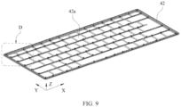
FIG. 9 is a schematic diagram of a partial structure of a keyboard according to an embodiment of this application; -
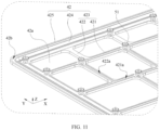
FIG. 10 is an enlarged schematic diagram of a location D inFIG. 9 ; -
FIG. 11 is a schematic diagram of a partial structure of a keyboard according to another embodiment of this application; and -
FIG. 12 is a schematic diagram of a partial structure of a keyboard according to still another embodiment of this application. -
- 1: Electronic device; 11: Display; 12: Host body;
- 2: Keyboard;
- 3: Keyboard assembly; 31: Circuit board unit; 311: Circuit board; 311a: First avoidance hole; 312: Metal sheet; 312a: Second avoidance hole; 313: Backlight module; 313a: Third avoidance hole; 32: Key; 321: Scissor leg assembly; 321a: External scissor leg; 321b: Inner scissor leg; 322: Keycap;
- 4: Keyboard frame assembly; 41: Outer metal frame; 41a: First opening; 41b: Outer surface; 41c: Inner surface; 41d: Accommodation concave part; 411: First board; 412: First side plate; 42: Inner metal frame; 42a: Second opening; 42b: Annular groove; 421: Transverse spacer; 421a: First concave part; 422: Longitudinal spacer; 422a: Second concave part; 423: Second board; 424: Second side plate; 425:
Flange 43; Key avoidance hole; - 5: Adaptation piece; 51: First component; 511: Tooth portion; 52: Second component; 521: Bolt; 522: Cap portion;
- 6: First adhesive member;
- 7: Second adhesive member;
- X: Length direction;
- Y: Width direction; and
- Z: Thickness direction.
- An embodiment of this application provides an
electronic device 1. Theelectronic device 1 may be a mobile terminal such as a desktop computer, a laptop computer (laptop), a tablet computer (Table), an ultra-mobile personal computer (ultra-mobile personal computer, UMPC), a handheld computer, a walkie-talkie, a netbook, a POS machine, or a personal digital assistant (personal digital assistant, PDA), a fixed terminal, or a foldable device. -
FIG. 1 schematically shows a three-dimensional structure of anelectronic device 1 according to an embodiment. Referring toFIG. 1 , in this embodiment of this application, an example in which theelectronic device 1 is a laptop computer is used for description. Theelectronic device 1 may include adisplay 11 and ahost body 12. Thedisplay 11 may be rotatably connected to thehost body 12. For example, thedisplay 11 and thehost body 12 may be connected by using a rotating shaft; or thedisplay 11 and thehost body 12 may be rotatably connected by using a hinge structure. Alternatively, in some examples, thedisplay 11 and thehost body 12 may be mutually independent devices. For example, thedisplay 11 and thehost body 12 are detachable. When being used, thedisplay 11 is placed on thehost body 12, and after the use, thedisplay 11 and thehost body 12 may be separated from each other. - It should be noted that, to implement a display effect of the
display 11, thedisplay 11 is electrically connected to thehost body 12. For example, thedisplay 11 may be electrically connected to thehost body 12 by using a contact, or thedisplay 11 is electrically connected to thehost body 12 by using a flexible circuit board (Flexible Printed Circuit, FPC), or thedisplay 11 is electrically connected to thehost body 12 by using a wire. In addition, alternatively, thedisplay 11 may be wirelessly connected to thehost body 12 by using a wireless signal. - Referring to
FIG. 1 , to implement an input to theelectronic device 1, theelectronic device 1 may further include akeyboard 2. Thekeyboard 2 may be disposed on thehost body 12. Thekeyboard 2 is electrically connected to a control unit in thehost body 12. Thekeyboard 2 serves as an input device of theelectronic device 1. Thekeyboard 2 may be used to enter a character or an operation instruction by using a key, and may further control a cursor to move. - Currently, the keyboard includes an outer metal frame, a plastic frame, a keyboard assembly, and a metal baseplate. The plastic frame is formed on the outer metal frame of the keyboard by using an injection molding process. The keyboard assembly is disposed between the outer metal frame and the metal baseplate. Both the keyboard assembly and the metal baseplate are attached to the plastic frame. The plastic frame carries the keyboard assembly and metal baseplate. A solder column protrudes from the plastic frame. The solder column penetrates through mounting holes of the keyboard assembly and the metal baseplate. An end portion that is of the solder column and that penetrates through the metal baseplate deforms through hot melting or pressing, and is clamped on a bottom surface that is of the metal baseplate and that faces away from the outer metal frame, to connect the keyboard assembly, the metal baseplate, and the plastic frame. The metal baseplate may serve as a strength enhancement structure, to improve overall rigidity of the keyboard, so as to resolve a problem that the outer metal frame sinks due to insufficient rigidity when the outer metal frame is pressed. However, the plastic frame and the metal baseplate lead to a large overall thickness of the keyboard. Consequently, portability of the keyboard is poor.
- Based on the foregoing found problem, an embodiment of this application provides a
keyboard 2. Aninner metal frame 42 is disposed between akeyboard assembly 3 and anouter metal frame 41, and theinner metal frame 42 carries thekeyboard assembly 3. In addition, theinner metal frame 42 has a strength enhancement function, to improve overall rigidity of thekeyboard 2. Therefore, a plastic frame and a metal baseplate in the keyboard can be canceled, to effectively reduce an overall thickness of thekeyboard 2, reduce a weight of thekeyboard 2, and help improve portability of thekeyboard 2. - An implementation of the
keyboard 2 provided in the embodiments of this application is described below. -
FIG. 2 schematically shows a structure of a keyboard according to an embodiment of this application. Referring toFIG. 1 andFIG. 2 , akeyboard 2 in this embodiment of this application includes akeyboard assembly 3 and akeyboard frame assembly 4. Thekeyboard assembly 3 is connected to thekeyboard frame assembly 4. Thekeyboard frame assembly 4 is configured to carry thekeyboard assembly 3, or provide protection for thekeyboard assembly 3 on an outer side of thekeyboard assembly 3. - Referring to
FIG. 2 andFIG. 3 , thekeyboard assembly 3 in this embodiment of this application includes acircuit board unit 31 and a plurality ofkeys 32 disposed on thecircuit board unit 31. Thecircuit board unit 31 and thekeys 32 are stacked in a thickness direction Z of thekeyboard 2. Thecircuit board unit 31 may provide support for each key 32. For a type of thekeys 32, refer to an existing key. For example, the plurality ofkeys 32 include a numeric key, a function key (for example, a Delete key or an Insert key), and a letter key. Thekeys 32 may be classified into a single-unit key and a multi-unit key based on sizes of the keys. The single-unit key is a square key 32 on thekeyboard 2, for example, a key 32 corresponding to each letter or each number. The multi-unit key is a key 32 other than the single-unit key, for example, a Space key, an Enter key, or a Shift key. - The
circuit board unit 31 includes acircuit board 311, ametal sheet 312, and abacklight module 313. Thecircuit board 311, themetal sheet 312, and thebacklight module 313 are stacked in the thickness direction Z of thekeyboard 2. Thecircuit board 311 is located on a side that is of themetal sheet 312 and on which the key 32 is disposed, and thebacklight module 313 is located on a side that is of themetal sheet 312 and that faces away from the key 32. Themetal sheet 312 can effectively improve a deformation resistance capability of thecircuit board unit 31, to reduce a possibility that thecircuit board 311 is broken when being bent or pulled. For example, thecircuit board 311 may be a flexible circuit board. A material of themetal sheet 312 may be steel, aluminum, or an aluminum alloy. For example, themetal sheet 312 may be a steel sheet. A thickness of themetal sheet 312 is 0.3 millimeter to 0.4 millimeter. - The key 32 includes a
scissor leg assembly 321 and akeycap 322. Thescissor leg assembly 321 is separately rotatably connected to thekeycap 322 and themetal sheet 312. Thescissor leg assembly 321 is disposed below thekeycap 322. Thescissor leg assembly 321 is configured to provide good support for thekeycap 322, so that a pressure stress exerted on thekeycap 322 can be balanced, and a user can press thekeycap 322 at any location on thekeycap 322 by exerting fixed pressure, to reduce a possibility that thekeycap 322 withstands uneven pressure or a key is stuck. For example, one or morescissor leg assemblies 321 may be disposed below onekeycap 322. For example, thescissor leg assembly 321 includes anouter scissor leg 321a and aninner scissor leg 321b. Theouter scissor leg 321a and theinner scissor leg 321b intersect with each other and are rotatably connected. Respective lower ends of theouter scissor leg 321a and theinner scissor leg 321b are rotatably connected to themetal sheet 312. Respective upper ends of theouter scissor leg 321a and theinner scissor leg 321b are rotatably connected to thekeycap 322. In some examples, theouter scissor leg 321a and theinner scissor leg 321b each may be of a box structure. - The
backlight module 313 may be configured to provide backlight for the key 32, so that in an environment with dark light, the user can clearly observe a corresponding key 32, to reduce a possibility that the key 32 is wrongly operated, and improve input accuracy and input efficiency. - In some implementable manners, the
backlight module 313 includes a light guide board (not shown in the figure) and a light-emitting unit (not shown in the figure). The light guide board has light guiding and light uniformization functions. Thebacklight module 313 may display the backlight by using the light guide board, to illuminate the key 32 in a corresponding region. The light emitting unit is configured to emit light into the light guide board. The light emitting unit may be disposed at a location near an edge of the light guide board. After being lit, the light emitting unit emits light into the light guide board. After the light is uniformized by the light guide board, a region of the 32 keys is illuminated. For example, the light emitting unit may be an LED lamp. - The
circuit board unit 31 and the key 32 of thekeyboard assembly 3 may be assembled to form a whole, and then are assembled with thekeyboard frame assembly 4 to form thekeyboard 2. -
FIG. 4 schematically shows a partial exploded structure of akeyboard 2 according to an embodiment of this application.FIG. 5 schematically shows a rear-side structure of akeyboard 2 according to an embodiment of this application. Referring toFIG. 4 andFIG. 5 , thekeyboard frame assembly 4 in this embodiment of this application includes anouter metal frame 41, aninner metal frame 42, and akey avoidance hole 43. Theinner metal frame 42 is connected to theouter metal frame 41. Thekey avoidance hole 43 penetrates through theouter metal frame 41 and theinner metal frame 42. Thekeyboard assembly 3 is connected to theinner metal frame 42. Theinner metal frame 42 is located between theouter metal frame 41 and thekeyboard assembly 3. Theinner metal frame 42 is configured to carry thekeyboard assembly 3. The key 32 is disposed in correspondence with thekey avoidance hole 43, so that the key 32 may be exposed from thekey avoidance hole 43, and the user taps the key 32 to execute an input instruction. - The
outer metal frame 41 may be of an integral structure, to help improve rigidity and a deformation resistance capability of theouter metal frame 41 while it is ensured that theouter metal frame 41 is lightweighted. Theouter metal frame 41 may be processed and manufactured in a processing manner such as stamping, die casting, or model casting. A material of theouter metal frame 41 may be aluminum, an aluminum alloy, or steel. Theouter metal frame 41 is provided with afirst opening 41a used to avoid the key 32. Thekey avoidance hole 43 includes thefirst opening 41a. Theouter metal frame 41 includes anouter surface 41b and aninner surface 41c that are opposite to each other. Thefirst opening 41a penetrates through theouter surface 41b and theinner surface 41c. It should be noted that theouter surface 41b of theouter metal frame 41 is a surface that is of theouter metal frame 41 and that faces the user when the user uses thekeyboard 2. Theinner surface 41c of theouter metal frame 41 is a surface that is of theouter metal frame 41 and that faces an inside of thekeyboard 2 when the user uses thekeyboard 2. In this case, the user cannot easily observe theinner surface 41c of theouter metal frame 41 from an outside of thekeyboard 2. - The
inner metal frame 42 is disposed on an inner side of theouter metal frame 41. Theinner metal frame 42 may be connected to theinner surface 41c of theouter metal frame 41. Theinner metal frame 42 may perform strength enhancement on theouter metal frame 41, to help reduce a possibility that theouter metal frame 41 sinks under pressure. Theinner metal frame 42 may be of an integral structure, to help improve rigidity and a deformation resistance capability of theinner metal frame 42 while it is ensured that theinner metal frame 42 is lightweighted. Theinner metal frame 42 may be processed and manufactured in a processing manner such as stamping, die casting, or model casting. For example, theinner metal frame 42 may be formed by stamping a flat plate. A material of theinner metal frame 42 may be aluminum, an aluminum alloy, or steel. Theinner metal frame 42 is provided with asecond opening 42a used to avoid the key 32. Thekey avoidance hole 43 includes thesecond opening 42a. For example, thefirst opening 41a and thesecond opening 42a are aligned and communicate to form thekey avoidance hole 43. -
FIG. 6 schematically shows a partial exploded structure of a keyboard according to an embodiment of this application. Referring toFIG. 5 andFIG. 6 , in some implementable manners, theouter metal frame 41 includes afirst board 411 and afirst side plate 412. Thefirst board 411 and thefirst side plate 412 intersect to form an accommodationconcave part 41d. Thefirst opening 41a is disposed on thefirst board 411. A heat dissipation hole may be disposed on thefirst side plate 412. Theinner metal frame 42 is located in the accommodationconcave part 41d. In the thickness direction Z of thekeyboard 2, theinner metal frame 42 and thefirst board 411 are stacked and connected to thefirst board 411. - The
keyboard assembly 3 is connected to theinner metal frame 42, so that theinner metal frame 42 can carry thekeyboard assembly 3. Thekeyboard assembly 3 is suspended below theinner metal frame 42. When the user taps the key 32, after a force is exerted on thekeyboard assembly 3, thekeyboard assembly 3 applies, to theinner metal frame 42, a tensile stress that is away from theouter metal frame 41, and theinner metal frame 42 applies, to theouter metal frame 41, a tensile stress that faces away from theinner surface 41c of theouter metal frame 41. Theinner metal frame 42 and theouter metal frame 41 are combined with each other, and theinner metal frame 42 has high rigidity and has a strength enhancement function. Therefore, when an external force is exerted on thekeyboard assembly 3, thekeyboard assembly 3 does not easily deform or sink, and thekeyboard assembly 3 does not easily pull theinner metal frame 42 and theouter metal frame 41 to deform or sink. - In the
keyboard 2 in this embodiment of this application, theinner metal frame 42 with the strength enhancement function is disposed between theouter metal frame 41 and thekeyboard assembly 3. Theinner metal frame 42 is connected to theouter metal frame 41, and thekeyboard assembly 3 is connected to theinner metal frame 42. Strength enhancement is performed on thekeyboard 2 by using the disposedinner metal frame 42, to improve a deformation resistance capability of thekeyboard 2, and reduce a possibility that thekeyboard 2 deforms and sinks when thekeyboard 2 suffers from an impact stress in a use process. Therefore, a metal baseplate and a plastic frame of a current keyboard can be canceled, to help reduce an overall thickness of thekeyboard 2 while it is ensured that rigidity of thekeyboard 2 meets a requirement, and improve portability of thekeyboard 2. - In the current keyboard, a solder column protrudes from the plastic frame. An end portion that is of the solder column and that penetrates through the metal baseplate deforms through hot melting or pressing, and is clamped on a bottom surface of the metal baseplate, to connect the keyboard assembly, the metal baseplate, and the plastic frame. In such a structure design, when the keyboard assembly needs to be repaired due to a fault, the keyboard assembly and the plastic frame can be separated only after the end portion of the solder column is cut off. Consequently, the plastic frame cannot be reused. The plastic frame and the outer metal frame are both scrapped. In this embodiment of this application, the
keyboard assembly 3 is detachably connected to theinner metal frame 42, so that thekeyboard assembly 3 can be removed from theinner metal frame 42 when thekeyboard assembly 3 needs to be repaired. After thekeyboard assembly 3 is repaired, thekeyboard assembly 3 is reinstalled on theinner metal frame 42, so that theinner metal frame 42 and theouter metal frame 41 can be reused, thereby reducing maintenance difficulty and maintenance costs. For example, thekeyboard assembly 3 and theinner metal frame 42 may be stuck by using an adhesive member. Alternatively, thekeyboard assembly 3 and theinner metal frame 42 may be snap-fitted by using a snap-fit. Alternatively, thekeyboard assembly 3 and theinner metal frame 42 may be fastened by using a fastener. For example, the fastener may be a screw. - The
keyboard assembly 3 includes thecircuit board unit 31. The key 32 is disposed on thecircuit board unit 31. Thecircuit board unit 31 provides support for the key 32. Thecircuit board unit 31 is disposed on a side that is of theinner metal frame 42 and that faces away from theouter metal frame 41. Thecircuit board unit 31 is detachably connected to theinner metal frame 42. Thecircuit board unit 31 is of a plate-like structure and has high rigidity. Therefore, thecircuit board unit 31 is connected to theinner metal frame 42, to effectively ensure stability and reliability of a connection between thecircuit board unit 31 and theinner metal frame 42, and reduce a possibility that thekeyboard assembly 3 and theinner metal frame 42 are loosened or separated due to frequent tapping. For example, thecircuit board unit 31 includes thecircuit board 311, themetal sheet 312, and thebacklight module 313. Thecircuit board 311 is disposed on a side that is of themetal sheet 312 and that faces theinner metal frame 42. Thecircuit board 311 may be a printed circuit board (Printed Circuit Board, PCB) or a flexible circuit board. Thebacklight module 313 is disposed on a side that is of themetal sheet 312 and that faces away from theinner metal frame 42. Thecircuit board 311 has signal collection and signal processing functions. When the key 32 is tapped, a corresponding region of thecircuit board 311 is triggered to execute a corresponding input instruction. Themetal sheet 312 of thecircuit board unit 31 is detachably connected to theinner metal frame 42. Light of thebacklight module 313 may penetrate through themetal sheet 312 and thecircuit board 311 and illuminate the key 32. - Referring to
FIG. 7 andFIG. 8 , thekeyboard 2 in this embodiment of this application further includes anadaptation piece 5. Thecircuit board unit 31 is detachably connected to theinner metal frame 42 by using theadaptation piece 5. For example, a part of theadaptation piece 5 is connected to thecircuit board unit 31, and the other part is connected to theinner metal frame 42, so that thecircuit board unit 31 is pressed against a surface that is of theinner metal frame 42 and that faces thecircuit board unit 31. In a manner in which thecircuit board unit 31 and theinner metal frame 42 are connected by using theadaptation piece 5, no connection structure needs to be additionally disposed on thecircuit board unit 31 or theinner metal frame 42 in an integrated manner, to help reduce processing and manufacturing difficulty of thecircuit board unit 31 and theinner metal frame 42. When thekeyboard assembly 3 needs to be repaired, theadaptation piece 5 may be removed to separate thekeyboard assembly 3 and theinner metal frame 42. - In some implementable manners, the
adaptation piece 5 includes afirst component 51 and asecond component 52. Thefirst component 51 and thesecond component 52 are independently disposed. After thefirst component 51 and thesecond component 52 are separately processed and manufactured, thefirst component 51 and thesecond component 52 may be connected to each other to form theadaptation piece 5. Thefirst component 51 is disposed on theinner metal frame 42. Thefirst component 51 may be detachably connected to theinner metal frame 42. After theinner metal frame 42 and theouter metal frame 41 are assembled, thefirst component 51 is connected to theinner metal frame 42. Alternatively, thefirst component 51 is connected to theinner metal frame 42 in advance, and then theinner metal frame 42 with thefirst component 51 is connected to theouter metal frame 41. Alternatively, thefirst component 51 may be directly built into or soldered onto theinner metal frame 42 to form an integral structure with theinner metal frame 42. Before theinner metal frame 42 and theouter metal frame 41 are assembled, thefirst component 51 is built into or soldered onto theinner metal frame 42, and then theinner metal frame 42 is connected to theouter metal frame 41. Therefore, in a process of connecting theinner metal frame 42 and theouter metal frame 41, thefirst component 51 is not easily separated from theinner metal frame 42 and lost. After being positioned, thekeyboard assembly 3 and theinner metal frame 42 are connected by using thesecond component 52 and thefirst component 51. Thefirst component 51 and thesecond component 52 are fastened to connect thecircuit board unit 31 and theinner metal frame 42. Thefirst component 51 and thesecond component 52 that are separately designed are used for theadaptation piece 5, so that thefirst component 51 is positioned and mounted on theinner metal frame 42 in advance, and then thekeyboard assembly 3 is fastened by using thesecond component 52. Therefore, thesecond component 52 may be directly aligned with thefirst component 51 to perform a connection operation, and thesecond component 52 does not need to be repositioned with respect to theinner metal frame 42. - The
first component 51 is threaded with thesecond component 52. One of thefirst component 51 and thesecond component 52 has an external thread, and the other has an internal thread. When thesecond component 52 is connected to thefirst component 51, the threads may guide thesecond component 52 to be aligned with thefirst component 51, to reduce difficulty in positioning thefirst component 51 and thesecond component 52 in alignment with each other, and help improve connection convenience and connection efficiency. After thefirst component 51 and thesecond component 52 are connected, thefirst component 51 and thesecond component 52 are easily self-locked, and have good anti-loosening performance and connection stability, to reduce a probability that a gap occurs between thekeyboard assembly 3 and theinner metal frame 42 after thefirst component 51 and thesecond component 52 are mutually loosened after long-term use, and thekeyboard assembly 3 becomes loose, affecting stability and comfort of tapping the key 32 by the user. - In some implementable manners, the
first component 51 is a nut. Theinner metal frame 42 includes a mounting hole. Thefirst component 51 is inserted into the mounting hole. Thefirst component 51 may be partially located in the mounting hole, and partially located outside the mounting hole, or may be integrally located in the mounting hole. For example, thefirst component 51 is pressed into the mounting hole of theinner metal frame 42 in an extrusion manner. Referring toFIG. 9 andFIG. 10 , atooth portion 511 may be disposed on a peripheral surface of thefirst component 51, so that after thefirst component 51 is pressed into the mounting hole, thetooth portion 511 of thefirst component 51 may be built into a hole wall of the mounting hole, to improve a bonding force and connection stability between thefirst component 51 and theinner metal frame 42, reduce a possibility that thefirst component 51 easily drops from theinner metal frame 42, and further reduce a possibility that thefirst component 51 rotates in the mounting hole when thefirst component 51 withstands torque. A plurality oftooth portions 511 are evenly distributed in an annular shape around thefirst component 51. Thesecond component 52 includes abolt 521 and acap portion 522 connected to thebolt 521. Thebolt 521 is threaded with thefirst component 51. Thebolt 521 has an external thread, and thefirst component 51 has an internal threaded hole that matches the external thread. Thecap portion 522 of thesecond component 52 abuts against thecircuit board unit 31, to apply, to thecircuit board unit 31, a pressure stress toward theinner metal frame 42. Thecap portion 522 of thesecond component 52 may carry thekeyboard assembly 3, and also limit thekeyboard assembly 3, to reduce a possibility that thekeyboard assembly 3 moves away from theinner metal frame 42. - In some examples, the
circuit board unit 31 includes thecircuit board 311, themetal sheet 312, and thebacklight module 313. Thecircuit board 311 includes afirst avoidance hole 311a. Themetal sheet 312 includes asecond avoidance hole 312a. Thebacklight module 313 includes athird avoidance hole 313a. Thefirst avoidance hole 311a, thesecond avoidance hole 312a, and thethird avoidance hole 313a are aligned, and communicate with each other. Thefirst component 51 is inserted into thefirst avoidance hole 311a and thesecond avoidance hole 312a, so that thecircuit board unit 31 may be positioned by using thefirst component 51, to quickly and accurately adjust relative locations of thecircuit board unit 31 and theinner metal frame 42. Thecap portion 522 of thesecond component 52 is accommodated in thethird avoidance hole 313a and abuts against a surface that is of themetal sheet 312 and that faces away from thecircuit board 311. Themetal sheet 312 has high rigidity. Therefore, when thesecond component 52 abuts against themetal sheet 312, and a large pressure stress may be applied to themetal sheet 312, to improve connection stability between thecircuit board unit 31 and theinner metal frame 42. Thesecond component 52 and themetal sheet 312 each are of a metal material. Therefore, after thecap portion 522 of thesecond component 52 abuts against themetal sheet 312, thecap portion 522 is not easily rotated and loosened relative to themetal sheet 312. Thecap portion 522 of thesecond component 52 is accommodated in thethird avoidance hole 313a. Space of thethird avoidance hole 313a may be used, to help reduce the overall thickness of thekeyboard 2. In addition, thebacklight module 313 may be avoided, to reduce a possibility that a structure of thebacklight module 313 is damaged because thecap portion 522 of thesecond component 52 abuts against thebacklight module 313. For example, thecap portion 522 of thesecond component 52 is integrally located in thethird avoidance hole 313a. A top surface that is of thecap portion 522 of thesecond component 52 and that faces away from theinner metal frame 42 is flush with an edge of thethird avoidance hole 313a formed in thebacklight module 313, or a top surface that is of thecap portion 522 of thesecond component 52 and that faces away from theinner metal frame 42 is lower than an edge of thethird avoidance hole 313a formed in thebacklight module 313, to reduce a possibility that thecap portion 522 of thesecond component 52 collides with or scratches an adjacent mechanical part. - As shown in
FIG. 10 , theinner metal frame 42 includes atransverse spacer 421 and alongitudinal spacer 422 that are connected to each other. For example, theentire keyboard 2 has a length and a width. Thetransverse spacer 421 extends in a length direction X of thekeyboard 2. Thelongitudinal spacer 422 extends in a width direction Y of thekeyboard 2. Thetransverse spacer 421 and thelongitudinal spacer 422 are alternately disposed around thekey avoidance hole 43. For example, twolongitudinal spacers 422 are disposed on a left side and a right side of eachkey avoidance hole 43, and twotransverse spacers 421 are disposed on an upper side and a lower side. A plurality oftransverse spacers 421 and a plurality oflongitudinal spacers 422 are classified to form a plurality ofsecond openings 42a. Thefirst component 51 is disposed in an intersection region of thetransverse spacer 421 and thelongitudinal spacer 422. The intersection region of thetransverse spacer 421 and thelongitudinal spacer 422 has a large area, and therefore, has high rigidity. When a tapping force impacts on thekeyboard assembly 3, an acting force is transmitted to theinner metal frame 42 through thefirst component 51. The intersection region of thetransverse spacer 421 and thelongitudinal spacer 422 has high rigidity, and has a strong deformation resistance capability. Therefore, under a pulling action of thefirst component 51, the intersection region of thetransverse spacer 421 and thelongitudinal spacer 422 does not easily deform or sink, to ensure that thekeyboard 2 can still remain structurally stable when withstanding impact. - In an embodiment in which the
inner metal frame 42 includes asecond board 423, thetransverse spacer 421 and thelongitudinal spacer 422 are disposed on thesecond board 423. - In this embodiment of this application, the
outer metal frame 41 and theinner metal frame 42 are detachably connected. Theouter metal frame 41 and theinner metal frame 42 each are independently processed and manufactured, and then are assembled. When theouter metal frame 41 or theinner metal frame 42 is repaired subsequently, theouter metal frame 41 and theinner metal frame 42 are separated. After being repaired, theouter metal frame 41 and theinner metal frame 42 are recombined, so that both theouter metal frame 41 and theinner metal frame 42 can be reused, to reduce maintenance difficulty and maintenance costs. - In some implementable manners, the
outer metal frame 41 includes anouter surface 41b and aninner surface 41c that are opposite in a thickness direction of theouter metal frame 41. Theinner metal frame 42 is stuck to theinner surface 41c. Before theinner metal frame 42 and theouter metal frame 41 are connected, a predetermined location of theouter metal frame 41 or a predetermined location of theinner metal frame 42 is coated with glue or an adhesive tape in advance, and then theinner metal frame 42 and theouter metal frame 41 are stuck and fastened. In a sticking manner, a connection structure may not need to be additionally disposed on theouter metal frame 41 or theinner metal frame 42 to connect and fasten theouter metal frame 41 and theinner metal frame 42, to reduce structural complexity of theouter metal frame 41 or theinner metal frame 42, and reduce processing difficulty of theouter metal frame 41 or theinner metal frame 42. In addition, a quantity of parts used for thekeyboard 2 is reduced, to help reduce an assembly process and assembly difficulty of thekeyboard 2. Furthermore, a glue coating thickness or a thickness of the adhesive tape is precisely controlled, to help further reduce the overall thickness of thekeyboard 2. - There is an annular accommodation cavity (not shown in the figure) between the
inner metal frame 42 and theinner surface 41c of theouter metal frame 41. Thekeyboard frame assembly 4 further includes a firstadhesive member 6 disposed in the annular accommodation cavity. For example, the firstadhesive member 6 is an adhesive tape or cured glue. Thekey avoidance hole 43 is located in a region limited by the annular accommodation cavity. The firstadhesive member 6 connects theouter metal frame 41 and theinner metal frame 42. Before theouter metal frame 41 and theinner metal frame 42 are assembled, the predetermined location of theouter metal frame 41 or the predetermined location of theinner metal frame 42 is coated with the glue or the adhesive tape in advance, and then theouter metal frame 41 and theinner metal frame 42 are stuck together. The glue or the adhesive tape is located in the annular accommodation cavity. The annular accommodation cavity may limit the glue or the adhesive tape, to reduce a possibility that the glue spills from space between theouter metal frame 41 and theinner metal frame 42 or that the adhesive tape is misaligned. For example, the annular accommodation cavity is a continuously extending cavity. Anannular groove 42b is disposed in an edge region of theinner metal frame 42, so that after theouter metal frame 41 and theinner metal frame 42 are combined, theannular groove 42b and theinner surface 41c of theouter metal frame 41 form the annular accommodation cavity. Thesecond opening 42a of theinner metal frame 42 is located in a region limited by theannular groove 42b. - In some implementable manners, the
inner metal frame 42 includes thesecond board 423, asecond side plate 424, and aflange 425. Thesecond side plate 424 and thesecond board 423 intersect. Theflange 425 and thesecond side plate 424 are connected. Thesecond board 423 includes thetransverse spacer 421, thelongitudinal spacer 422, and thesecond opening 42a formed through division of thetransverse spacer 421 and thelongitudinal spacer 422. Theannular groove 42b is disposed on a surface that is of theflange 425 and that faces theouter metal frame 41. - In some examples, there is a first chamber (not shown in the figure) between the
transverse spacer 421 and theinner surface 41c. Thekeyboard frame assembly 4 further includes a secondadhesive member 7 disposed in the first chamber. For example, the secondadhesive member 7 is an adhesive tape or cured glue. The secondadhesive member 7 connects theouter metal frame 41 and theinner metal frame 42. Before theouter metal frame 41 and theinner metal frame 42 are assembled, the predetermined location of theouter metal frame 41 or the predetermined location of theinner metal frame 42 is coated with the glue or the adhesive tape in advance, and then theouter metal frame 41 and theinner metal frame 42 are stuck together. The glue or the adhesive tape is located in the first chamber. The first chamber may limit the glue or the adhesive tape, to reduce the possibility that the glue spills from space between theouter metal frame 41 and theinner metal frame 42 or that the adhesive tape is misaligned. For example,FIG. 11 andFIG. 12 each schematically show a partial structure of akeyboard 2 according to an embodiment of this application. Referring toFIG. 11 andFIG. 12 , a firstconcave part 421a is disposed on thetransverse spacer 421 of theinner metal frame 42, so that after theouter metal frame 41 and theinner metal frame 42 are combined, the firstconcave part 421a and theinner surface 41c of theouter metal frame 41 form the first chamber. Before theouter metal frame 41 and theinner metal frame 42 are assembled, an inside of the firstconcave part 421a is coated with glue or an adhesive tape in advance. The firstadhesive member 6 and the secondadhesive member 7 jointly connect theouter metal frame 41 and theinner metal frame 42, to help further improve connection strength of theouter metal frame 41 and theinner metal frame 42. - In some other examples, there is a second chamber (not shown in the figure) between the
longitudinal spacer 422 and theinner surface 41c of theouter metal frame 41. Thekeyboard frame assembly 4 further includes a secondadhesive member 7 disposed in the second chamber. Before theouter metal frame 41 and theinner metal frame 42 are assembled, the predetermined location of theouter metal frame 41 or the predetermined location of theinner metal frame 42 is coated with the glue or the adhesive tape in advance, and then theouter metal frame 41 and theinner metal frame 42 are stuck together. The glue or the adhesive tape is located in the second chamber. The second chamber may limit the glue or the adhesive tape, to reduce the possibility that the glue spills from space between theouter metal frame 41 and theinner metal frame 42 or that the adhesive tape is misaligned. For example, referring toFIG. 11 andFIG. 12 , a secondconcave part 422a is disposed on thelongitudinal spacer 422 of theinner metal frame 42, so that after theouter metal frame 41 and theinner metal frame 42 are combined, the secondconcave part 422a and theinner surface 41c of theouter metal frame 41 form the second chamber. Before theouter metal frame 41 and theinner metal frame 42 are assembled, an inside of the secondconcave part 422a is coated with glue or an adhesive tape in advance. - It can be understood that there is a first chamber between the
transverse spacer 421 and theinner surface 41c, and there is a second chamber between thelongitudinal spacer 422 and theinner surface 41c. Thekeyboard frame assembly 4 further includes a secondadhesive member 7 disposed in the first chamber and the second chamber. The first chamber and the second chamber may communicate. In the embodiment in which thefirst component 51 is a nut, thefirst component 51 may be disposed at an intersection of the first chamber and the second chamber, and an end surface that is of thefirst component 51 and that faces theouter metal frame 41 is exposed from theinner metal frame 42, so that glue or an adhesive tape can connect thefirst component 51 and theouter metal frame 41. When thefirst component 51 suffers from a tensile stress of pulling thefirst component 51 away from theouter metal frame 41, a part that is of theouter metal frame 41 and that corresponds to thefirst component 51 may exert an opposite acting force on thefirst component 51, to further reduce a possibility that thefirst component 51 and theinner metal frame 42 move away from theouter metal frame 41. - An embodiment of this application provides a method for manufacturing a
keyboard 2, including: - providing a first board, and processing and manufacturing the first board, to form an
outer metal frame 41 including afirst opening 41a; - providing a second board, and processing and manufacturing the second board, to form an
inner metal frame 42 including asecond opening 42a; - connecting the
outer metal frame 41 and theinner metal frame 42, where thefirst opening 41a and thesecond opening 42a are correspondingly disposed, and thefirst opening 41a and thesecond opening 42a communicate to form akey avoidance hole 43; - providing a
keyboard assembly 3 including acircuit board unit 31 and a key 32, where thekeyboard assembly 3 is positioned on theinner metal frame 42, the key 32 of thekeyboard assembly 3 is aligned with thekey avoidance hole 43, and thecircuit board unit 31 of thekeyboard assembly 3 is located on a side that is of theinner metal frame 42 and that faces away from theouter metal frame 41; and - connecting and combining the
keyboard assembly 3 and theinner metal frame 42, to form thekeyboard 2. - In the method for manufacturing a
keyboard 2 in this embodiment, thekeyboard 2 in the foregoing embodiment may be manufactured. - In the descriptions of the embodiments of this application, it should be noted that unless otherwise specified or limited, terms "mount", "communicate", and "connect" shall be understood in a broad sense, for example, may be a fixed connection, may be an indirect connection by using an intermediate medium, or may be a connection between insides of two elements or an interaction relationship between two elements. A person of ordinary skill in the art may understand specific meanings of the foregoing terms in the embodiments of this application based on a specific situation.
- The apparatus or element referred to in or implied in the embodiments of this application needs to have a specific orientation, be constructed and operated in a specific orientation, and therefore cannot be construed as a limitation on the embodiments of this specification. In the descriptions of the embodiments of this application, "a plurality of" means two or more, unless otherwise specifically specified.
- The terms "first", "second", "third", "fourth", and the like (if existent) in the specification, claims, and accompanying drawings of the embodiments of this application are used to distinguish between similar objects, but are not necessarily used to describe a particular order or sequence. It should be understood that the data used in such a way is interchangeable in proper situations, so that the embodiments of the embodiments of this application described herein can be implemented, for example, in a sequence other than those illustrated or described herein. In addition, the terms "include", "have", and any variation thereof are intended to cover non-exclusive inclusions. For example, a process, a method, a system, a product, or a device that includes a series of steps or units is not necessarily limited to those steps or units that are clearly listed, but may include other steps or units that are not clearly listed or are inherent to the process, method, product, or device.
- Unless otherwise specified, "a plurality of" in this specification indicates two or more. The term "and/or" in this specification describes only an association relationship between associated objects and represents that three relationships can exist. For example, "A and/or B" can represent the following three cases: Only A exists, both A and B exist, and only B exists. In addition, the character "/" in this specification usually indicates an "or" relationship between the associated objects. In a formula, the character "/" indicates that the associated objects are in a "division" relationship.
- It can be understood that various numeric numbers used in the embodiments of this application are merely described for easy differentiation, and are not intended to limit the scope of the embodiments of this application.
- It should be understood that, in the embodiments of this application, sequence numbers of the foregoing processes do not mean execution sequences. The execution sequences of the processes should be determined based on functions and internal logic of the processes, and should not be construed as any limitation on the implementation processes of the embodiments of this application.
Claims (14)
- A keyboard, applied to an electronic device, wherein the keyboard comprises at least the following:a keyboard assembly, comprising a key; anda keyboard frame assembly, comprising an outer metal frame, an inner metal frame, and a key avoidance hole, wherein the inner metal frame is connected to the outer metal frame, the key avoidance hole penetrates through the outer metal frame and the inner metal frame, the keyboard assembly is connected to the inner metal frame, the inner metal frame is located between the outer metal frame and the keyboard assembly, the inner metal frame is configured to carry the keyboard assembly, and the key is disposed in correspondence with the key avoidance hole.
- The keyboard according to claim 1, wherein the keyboard assembly is detachably connected to the inner metal frame.
- The keyboard according to claim 2, wherein the keyboard assembly further comprises a circuit board unit, the key is disposed on the circuit board unit, the circuit board unit is disposed on a side that is of the inner metal frame and that faces away from the outer metal frame, and the circuit board unit is detachably connected to the inner metal frame.
- The keyboard according to claim 3, wherein the keyboard further comprises an adaptation piece, and the circuit board unit is detachably connected to the inner metal frame by using the adaptation piece.
- The keyboard according to claim 4, wherein the adaptation piece comprises a first component and a second component, the first component is disposed on the inner metal frame, and the first component and the second component are fastened to connect the circuit board unit and the inner metal frame.
- The keyboard according to claim 5, wherein the first component is threaded with the second component.
- The keyboard according to claim 6, wherein the first component is a nut, the inner metal frame comprises a mounting hole, the first component is inserted into the mounting hole, the second component comprises a bolt and a cap portion connected to the bolt, the bolt is threaded with the first component, and the cap portion abuts against the circuit board unit to apply, to the circuit board unit, a pressure stress toward the inner metal frame.
- The keyboard according to claim 7, wherein the circuit board unit comprises a circuit board, a metal sheet, and a backlight module, the circuit board is disposed on a side that is of the metal sheet and that faces the inner metal frame, the backlight module is disposed on a side that is of the metal sheet and that faces away from the inner metal frame, the circuit board comprises a first avoidance hole, the metal sheet comprises a second avoidance hole, the backlight module comprises a third avoidance hole, the first component is inserted into the first avoidance hole and the second avoidance hole, and the cap portion is accommodated in the third avoidance hole and abuts against a surface that is of the metal sheet and that faces away from the circuit board.
- The keyboard according to any one of claims 5 to 8, wherein the inner metal frame comprises a transverse spacer and a longitudinal spacer, the transverse spacer and the longitudinal spacer are alternately disposed around the key avoidance hole, and the first component is disposed in an intersection region of the transverse spacer and the longitudinal spacer.
- The keyboard according to any one of claims 1 to 8, wherein the outer metal frame and the inner metal frame are detachably connected.
- The keyboard according to claim 10, wherein the outer metal frame comprises an outer surface and an inner surface, and the inner metal frame is stuck to the inner surface.
- The keyboard according to claim 11, wherein there is an annular accommodation cavity between the inner metal frame and the inner surface, the keyboard frame assembly further comprises a first adhesive member disposed within the annular accommodation cavity, the key avoidance hole is located within a region limited by the annular accommodation cavity, and the first adhesive member connects the outer metal frame and the inner metal frame.
- The keyboard according to claim 11, wherein the inner metal frame comprises a transverse spacer and a longitudinal spacer, and the transverse spacer and the longitudinal spacer are alternately disposed around the key avoidance hole;there is a first chamber between the transverse spacer and the inner surface, and the keyboard frame assembly further comprises a second adhesive member disposed in the first chamber; orthere is a second chamber between the longitudinal spacer and the inner surface, and the keyboard frame assembly further comprises a second adhesive member disposed in the second chamber; orthere is a first chamber between the transverse spacer and the inner surface, there is a second chamber between the longitudinal spacer and the inner surface, and the keyboard frame assembly further comprises a second adhesive member disposed in the first chamber and the second chamber; andthe second adhesive member connects the outer metal frame and the inner metal frame.
- An electronic device, comprising the keyboard according to any one of claims 1 to 13.
Applications Claiming Priority (2)
| Application Number | Priority Date | Filing Date | Title |
|---|---|---|---|
| CN202110867785.2A CN113778234A (en) | 2021-07-29 | 2021-07-29 | Keyboards and Electronic Devices |
| PCT/CN2022/090796 WO2023005310A1 (en) | 2021-07-29 | 2022-04-29 | Keyboard and electronic device |
Publications (3)
| Publication Number | Publication Date |
|---|---|
| EP4286997A1 true EP4286997A1 (en) | 2023-12-06 |
| EP4286997A4 EP4286997A4 (en) | 2024-07-24 |
| EP4286997B1 EP4286997B1 (en) | 2025-06-18 |
Family
ID=78836506
Family Applications (1)
| Application Number | Title | Priority Date | Filing Date |
|---|---|---|---|
| EP22847925.9A Active EP4286997B1 (en) | 2021-07-29 | 2022-04-29 | Keyboard and electronic device |
Country Status (4)
| Country | Link |
|---|---|
| US (1) | US12189868B2 (en) |
| EP (1) | EP4286997B1 (en) |
| CN (1) | CN113778234A (en) |
| WO (1) | WO2023005310A1 (en) |
Families Citing this family (3)
| Publication number | Priority date | Publication date | Assignee | Title |
|---|---|---|---|---|
| CN113778234A (en) * | 2021-07-29 | 2021-12-10 | 荣耀终端有限公司 | Keyboards and Electronic Devices |
| US20240028083A1 (en) * | 2022-07-19 | 2024-01-25 | Hewlett-Packard Development Company, L.P. | Brackets for mounting electronic components |
| CN116382428B (en) * | 2023-06-06 | 2023-10-20 | 荣耀终端有限公司 | Electronic equipment and keyboard assembly |
Family Cites Families (19)
| Publication number | Priority date | Publication date | Assignee | Title |
|---|---|---|---|---|
| KR100614645B1 (en) | 2004-06-03 | 2006-08-22 | 삼성전자주식회사 | Power-On Reset Circuit |
| TWI266582B (en) * | 2004-07-06 | 2006-11-11 | Lg Electronics Inc | Hinge frame for portable computer and structure for mounting the same |
| JP5083078B2 (en) | 2008-07-11 | 2012-11-28 | ソニー株式会社 | Keyboard and keyboard manufacturing method |
| CN201438292U (en) * | 2009-05-19 | 2010-04-14 | 精元电脑股份有限公司 | Ultrathin keyboard device |
| TWI436395B (en) * | 2011-09-30 | 2014-05-01 | 宏碁股份有限公司 | Keyboard frame with better structural strength |
| DE202012104777U1 (en) * | 2012-12-07 | 2014-03-11 | Prehkeytec Gmbh | Rubber mat keyboard, in particular silicone mat keyboard |
| CN105304387A (en) * | 2015-07-20 | 2016-02-03 | 杨立涛 | Key and keyboard |
| TWI620220B (en) * | 2016-03-25 | 2018-04-01 | 致伸科技股份有限公司 | Keyboard and notebook computer to which the keyboard is applied |
| TWI584325B (en) * | 2016-08-19 | 2017-05-21 | 致伸科技股份有限公司 | Keyboard device and scissors connecting member thereof |
| JP6412626B1 (en) * | 2017-06-20 | 2018-10-24 | レノボ・シンガポール・プライベート・リミテッド | Keyboard device and electronic device |
| CN110908444B (en) * | 2019-12-04 | 2022-11-22 | 联想(北京)有限公司 | Input device |
| JP6846547B1 (en) * | 2020-01-09 | 2021-03-24 | レノボ・シンガポール・プライベート・リミテッド | Electronics |
| CN111506202B (en) * | 2020-04-17 | 2023-09-12 | 光宝科技(常州)有限公司 | Keyboard and keyboard assembling method |
| CN111403211B (en) | 2020-05-06 | 2022-03-11 | 光宝科技(常州)有限公司 | Keyboard frame and keyboard |
| CN111739752B (en) * | 2020-05-27 | 2023-05-23 | 淮安达方电子有限公司 | Keyboard and its keys and adjustment mechanism |
| CN212723808U (en) | 2020-08-31 | 2021-03-16 | 重庆广道精密电子有限公司 | A laptop keyboard frame |
| CN114840055B (en) * | 2021-01-30 | 2024-09-24 | 华为技术有限公司 | Keyboards and electronic devices |
| CN113778234A (en) * | 2021-07-29 | 2021-12-10 | 荣耀终端有限公司 | Keyboards and Electronic Devices |
| JP2023161363A (en) * | 2022-04-25 | 2023-11-07 | レノボ・シンガポール・プライベート・リミテッド | Keyboard devices and electronic equipment |
-
2021
- 2021-07-29 CN CN202110867785.2A patent/CN113778234A/en active Pending
-
2022
- 2022-04-29 WO PCT/CN2022/090796 patent/WO2023005310A1/en not_active Ceased
- 2022-04-29 US US18/282,633 patent/US12189868B2/en active Active
- 2022-04-29 EP EP22847925.9A patent/EP4286997B1/en active Active
Also Published As
| Publication number | Publication date |
|---|---|
| WO2023005310A1 (en) | 2023-02-02 |
| EP4286997A4 (en) | 2024-07-24 |
| EP4286997B1 (en) | 2025-06-18 |
| US12189868B2 (en) | 2025-01-07 |
| CN113778234A (en) | 2021-12-10 |
| US20240176426A1 (en) | 2024-05-30 |
Similar Documents
| Publication | Publication Date | Title |
|---|---|---|
| EP4286997B1 (en) | Keyboard and electronic device | |
| TWI689957B (en) | Keyboard device | |
| US8376603B2 (en) | Multi-segmented light guide for an input device | |
| US10825620B2 (en) | Light guiding substrate for a keyboard | |
| US8188400B2 (en) | Wireless dongle | |
| US20130149168A1 (en) | Mounting apparatus for fan | |
| US10276328B1 (en) | Keyboard structure | |
| JP2017076213A (en) | INPUT DEVICE, ELECTRONIC DEVICE, AND METHOD FOR MANUFACTURING INPUT DEVICE | |
| CN202871649U (en) | Luminous keyboard | |
| US8302521B2 (en) | Die with a punch module | |
| US20120189401A1 (en) | Fastening structure | |
| US10650986B2 (en) | Keyboard | |
| US20130334022A1 (en) | Keyswitch and Keyboard Including the Same | |
| US9941077B2 (en) | Computer thin film switch keyboard | |
| CN114023587B (en) | A sandwich sheet-type luminous key core module with light guide film | |
| US20140173877A1 (en) | Holeless plate member riveting method | |
| US20200333887A1 (en) | Sinkable keyboard device | |
| CN210050071U (en) | Luminous fan with quick-release structure | |
| US11966073B2 (en) | Reflective four-in-one light-emitting key core module | |
| US20230141940A1 (en) | Straight-through three-in-one light-emitting key core module | |
| CN201853595U (en) | Keys and keyboards | |
| CN115692075A (en) | Backlight module | |
| CN101892999A (en) | Fan unit and electronic equipment device equipped with the unit | |
| CN108962657B (en) | Keyboard | |
| KR20150078568A (en) | The stabbing preventing device of the pad in blanking of man power press of flexible circuit board |
Legal Events
| Date | Code | Title | Description |
|---|---|---|---|
| STAA | Information on the status of an ep patent application or granted ep patent |
Free format text: STATUS: THE INTERNATIONAL PUBLICATION HAS BEEN MADE |
|
| PUAI | Public reference made under article 153(3) epc to a published international application that has entered the european phase |
Free format text: ORIGINAL CODE: 0009012 |
|
| STAA | Information on the status of an ep patent application or granted ep patent |
Free format text: STATUS: REQUEST FOR EXAMINATION WAS MADE |
|
| 17P | Request for examination filed |
Effective date: 20230829 |
|
| AK | Designated contracting states |
Kind code of ref document: A1 Designated state(s): AL AT BE BG CH CY CZ DE DK EE ES FI FR GB GR HR HU IE IS IT LI LT LU LV MC MK MT NL NO PL PT RO RS SE SI SK SM TR |
|
| A4 | Supplementary search report drawn up and despatched |
Effective date: 20240624 |
|
| RIC1 | Information provided on ipc code assigned before grant |
Ipc: H01H 13/86 20060101ALI20240618BHEP Ipc: G06F 1/16 20060101ALI20240618BHEP Ipc: G06F 3/02 20060101AFI20240618BHEP |
|
| DAV | Request for validation of the european patent (deleted) | ||
| DAX | Request for extension of the european patent (deleted) | ||
| GRAP | Despatch of communication of intention to grant a patent |
Free format text: ORIGINAL CODE: EPIDOSNIGR1 |
|
| STAA | Information on the status of an ep patent application or granted ep patent |
Free format text: STATUS: GRANT OF PATENT IS INTENDED |
|
| INTG | Intention to grant announced |
Effective date: 20250115 |
|
| GRAS | Grant fee paid |
Free format text: ORIGINAL CODE: EPIDOSNIGR3 |
|
| GRAA | (expected) grant |
Free format text: ORIGINAL CODE: 0009210 |
|
| STAA | Information on the status of an ep patent application or granted ep patent |
Free format text: STATUS: THE PATENT HAS BEEN GRANTED |
|
| AK | Designated contracting states |
Kind code of ref document: B1 Designated state(s): AL AT BE BG CH CY CZ DE DK EE ES FI FR GB GR HR HU IE IS IT LI LT LU LV MC MK MT NL NO PL PT RO RS SE SI SK SM TR |
|
| REG | Reference to a national code |
Ref country code: GB Ref legal event code: FG4D |
|
| REG | Reference to a national code |
Ref country code: CH Ref legal event code: EP |
|
| REG | Reference to a national code |
Ref country code: DE Ref legal event code: R096 Ref document number: 602022016229 Country of ref document: DE |
|
| REG | Reference to a national code |
Ref country code: CH Ref legal event code: EP |
|
| REG | Reference to a national code |
Ref country code: IE Ref legal event code: FG4D |
|
| REG | Reference to a national code |
Ref country code: NL Ref legal event code: FP |
|
| PG25 | Lapsed in a contracting state [announced via postgrant information from national office to epo] |
Ref country code: FI Free format text: LAPSE BECAUSE OF FAILURE TO SUBMIT A TRANSLATION OF THE DESCRIPTION OR TO PAY THE FEE WITHIN THE PRESCRIBED TIME-LIMIT Effective date: 20250618 |
|
| REG | Reference to a national code |
Ref country code: LT Ref legal event code: MG9D |
|
| PG25 | Lapsed in a contracting state [announced via postgrant information from national office to epo] |
Ref country code: GR Free format text: LAPSE BECAUSE OF FAILURE TO SUBMIT A TRANSLATION OF THE DESCRIPTION OR TO PAY THE FEE WITHIN THE PRESCRIBED TIME-LIMIT Effective date: 20250919 Ref country code: NO Free format text: LAPSE BECAUSE OF FAILURE TO SUBMIT A TRANSLATION OF THE DESCRIPTION OR TO PAY THE FEE WITHIN THE PRESCRIBED TIME-LIMIT Effective date: 20250918 |
|
| PG25 | Lapsed in a contracting state [announced via postgrant information from national office to epo] |
Ref country code: BG Free format text: LAPSE BECAUSE OF FAILURE TO SUBMIT A TRANSLATION OF THE DESCRIPTION OR TO PAY THE FEE WITHIN THE PRESCRIBED TIME-LIMIT Effective date: 20250618 |
|
| PG25 | Lapsed in a contracting state [announced via postgrant information from national office to epo] |
Ref country code: HR Free format text: LAPSE BECAUSE OF FAILURE TO SUBMIT A TRANSLATION OF THE DESCRIPTION OR TO PAY THE FEE WITHIN THE PRESCRIBED TIME-LIMIT Effective date: 20250618 |
|
| PG25 | Lapsed in a contracting state [announced via postgrant information from national office to epo] |
Ref country code: RS Free format text: LAPSE BECAUSE OF FAILURE TO SUBMIT A TRANSLATION OF THE DESCRIPTION OR TO PAY THE FEE WITHIN THE PRESCRIBED TIME-LIMIT Effective date: 20250918 |
|
| PG25 | Lapsed in a contracting state [announced via postgrant information from national office to epo] |
Ref country code: LV Free format text: LAPSE BECAUSE OF FAILURE TO SUBMIT A TRANSLATION OF THE DESCRIPTION OR TO PAY THE FEE WITHIN THE PRESCRIBED TIME-LIMIT Effective date: 20250618 |
|
| PG25 | Lapsed in a contracting state [announced via postgrant information from national office to epo] |
Ref country code: PT Free format text: LAPSE BECAUSE OF FAILURE TO SUBMIT A TRANSLATION OF THE DESCRIPTION OR TO PAY THE FEE WITHIN THE PRESCRIBED TIME-LIMIT Effective date: 20251020 |
|
| REG | Reference to a national code |
Ref country code: AT Ref legal event code: MK05 Ref document number: 1804801 Country of ref document: AT Kind code of ref document: T Effective date: 20250618 |
|
| PG25 | Lapsed in a contracting state [announced via postgrant information from national office to epo] |
Ref country code: IS Free format text: LAPSE BECAUSE OF FAILURE TO SUBMIT A TRANSLATION OF THE DESCRIPTION OR TO PAY THE FEE WITHIN THE PRESCRIBED TIME-LIMIT Effective date: 20251018 |
|
| PG25 | Lapsed in a contracting state [announced via postgrant information from national office to epo] |
Ref country code: SM Free format text: LAPSE BECAUSE OF FAILURE TO SUBMIT A TRANSLATION OF THE DESCRIPTION OR TO PAY THE FEE WITHIN THE PRESCRIBED TIME-LIMIT Effective date: 20250618 Ref country code: AT Free format text: LAPSE BECAUSE OF FAILURE TO SUBMIT A TRANSLATION OF THE DESCRIPTION OR TO PAY THE FEE WITHIN THE PRESCRIBED TIME-LIMIT Effective date: 20250618 |
|
| PG25 | Lapsed in a contracting state [announced via postgrant information from national office to epo] |
Ref country code: CZ Free format text: LAPSE BECAUSE OF FAILURE TO SUBMIT A TRANSLATION OF THE DESCRIPTION OR TO PAY THE FEE WITHIN THE PRESCRIBED TIME-LIMIT Effective date: 20250618 |
|
| PG25 | Lapsed in a contracting state [announced via postgrant information from national office to epo] |
Ref country code: PL Free format text: LAPSE BECAUSE OF FAILURE TO SUBMIT A TRANSLATION OF THE DESCRIPTION OR TO PAY THE FEE WITHIN THE PRESCRIBED TIME-LIMIT Effective date: 20250618 |
|
| PG25 | Lapsed in a contracting state [announced via postgrant information from national office to epo] |
Ref country code: EE Free format text: LAPSE BECAUSE OF FAILURE TO SUBMIT A TRANSLATION OF THE DESCRIPTION OR TO PAY THE FEE WITHIN THE PRESCRIBED TIME-LIMIT Effective date: 20250618 |
|
| PG25 | Lapsed in a contracting state [announced via postgrant information from national office to epo] |
Ref country code: SK Free format text: LAPSE BECAUSE OF FAILURE TO SUBMIT A TRANSLATION OF THE DESCRIPTION OR TO PAY THE FEE WITHIN THE PRESCRIBED TIME-LIMIT Effective date: 20250618 |
|
| PG25 | Lapsed in a contracting state [announced via postgrant information from national office to epo] |
Ref country code: ES Free format text: LAPSE BECAUSE OF FAILURE TO SUBMIT A TRANSLATION OF THE DESCRIPTION OR TO PAY THE FEE WITHIN THE PRESCRIBED TIME-LIMIT Effective date: 20250618 |
|
| REG | Reference to a national code |
Ref country code: DE Ref legal event code: R097 Ref document number: 602022016229 Country of ref document: DE |
|
| PGFP | Annual fee paid to national office [announced via postgrant information from national office to epo] |
Ref country code: GB Payment date: 20260312 Year of fee payment: 5 |
|
| PG25 | Lapsed in a contracting state [announced via postgrant information from national office to epo] |
Ref country code: DK Free format text: LAPSE BECAUSE OF FAILURE TO SUBMIT A TRANSLATION OF THE DESCRIPTION OR TO PAY THE FEE WITHIN THE PRESCRIBED TIME-LIMIT Effective date: 20250618 |
|
| PG25 | Lapsed in a contracting state [announced via postgrant information from national office to epo] |
Ref country code: IT Free format text: LAPSE BECAUSE OF FAILURE TO SUBMIT A TRANSLATION OF THE DESCRIPTION OR TO PAY THE FEE WITHIN THE PRESCRIBED TIME-LIMIT Effective date: 20250618 |
|
| PGFP | Annual fee paid to national office [announced via postgrant information from national office to epo] |
Ref country code: NL Payment date: 20260317 Year of fee payment: 5 |
|
| PLBE | No opposition filed within time limit |
Free format text: ORIGINAL CODE: 0009261 |
|
| STAA | Information on the status of an ep patent application or granted ep patent |
Free format text: STATUS: NO OPPOSITION FILED WITHIN TIME LIMIT |
|
| REG | Reference to a national code |
Ref country code: CH Ref legal event code: L10 Free format text: ST27 STATUS EVENT CODE: U-0-0-L10-L00 (AS PROVIDED BY THE NATIONAL OFFICE) Effective date: 20260430 |