EP4286595A1 - Schacht - Google Patents
Schacht Download PDFInfo
- Publication number
- EP4286595A1 EP4286595A1 EP23166711.4A EP23166711A EP4286595A1 EP 4286595 A1 EP4286595 A1 EP 4286595A1 EP 23166711 A EP23166711 A EP 23166711A EP 4286595 A1 EP4286595 A1 EP 4286595A1
- Authority
- EP
- European Patent Office
- Prior art keywords
- shaft
- head frame
- walls
- shaft walls
- frame
- Prior art date
- Legal status (The legal status is an assumption and is not a legal conclusion. Google has not performed a legal analysis and makes no representation as to the accuracy of the status listed.)
- Granted
Links
Images




Classifications
-
- E—FIXED CONSTRUCTIONS
- E02—HYDRAULIC ENGINEERING; FOUNDATIONS; SOIL SHIFTING
- E02D—FOUNDATIONS; EXCAVATIONS; EMBANKMENTS; UNDERGROUND OR UNDERWATER STRUCTURES
- E02D29/00—Independent underground or underwater structures; Retaining walls
- E02D29/12—Manhole shafts; Other inspection or access chambers; Accessories therefor
- E02D29/124—Shaft entirely made of synthetic material
-
- E—FIXED CONSTRUCTIONS
- E02—HYDRAULIC ENGINEERING; FOUNDATIONS; SOIL SHIFTING
- E02D—FOUNDATIONS; EXCAVATIONS; EMBANKMENTS; UNDERGROUND OR UNDERWATER STRUCTURES
- E02D29/00—Independent underground or underwater structures; Retaining walls
- E02D29/12—Manhole shafts; Other inspection or access chambers; Accessories therefor
-
- H—ELECTRICITY
- H02—GENERATION; CONVERSION OR DISTRIBUTION OF ELECTRIC POWER
- H02G—INSTALLATION OF ELECTRIC CABLES OR LINES, OR OF COMBINED OPTICAL AND ELECTRIC CABLES OR LINES
- H02G9/00—Installations of electric cables or lines in or on the ground or water
- H02G9/10—Installations of electric cables or lines in or on the ground or water in cable chambers, e.g. in manhole or in handhole
Definitions
- the invention relates to a shaft, the shaft walls of which consist of wall elements placed on top of each other, which are produced using the injection molding process.
- a shaft the shaft walls of which consist of wall elements placed on top of each other, which are produced using the injection molding process.
- two or three rows of wall elements are arranged one above the other, with the upper end of the shaft walls formed in this way having a steel frame made of a circumferential rectangular profile, on which one or more manhole covers are arranged, which are surrounded by flat steel attached to the outside of the steel frame.
- the top edge of the flat steel and the top of the manhole cover(s) must be at the same height as the surrounding area of the manhole.
- the steel frame can be supported on spindles, the length of which is adjusted so that the manhole cover or covers are at ambient level.
- the manhole cover or covers can be exposed to high mechanical loads from motor vehicle traffic depending on the installation location, the upper end of the manhole must have sufficient stability.
- the present invention is based on the object of specifying a shaft in which the upper end can be assembled quickly and easily. This object is achieved according to the invention by the features of patent claim 1.
- the invention provides that a head frame rests on the top of the shaft walls, which is fixed to the shaft walls by clamping means and/or locking means, and that the steel frame rests either directly on the head frame or on a lining layer of mortar arranged on the head frame .
- the head frame can be assembled in a simple manner without the use of tools, while still ensuring that the head frame is held immovably on the shaft walls under all loads that occur.
- the steel frame lies either on the head frame or on a lining layer of mortar arranged on the head frame when the steel frame is raised with the help of extended spindles.
- the head frame is preferably made of plastic, preferably PC, using an injection molding process.
- the head frame is composed of several head frame parts. If - as is preferred - the shaft has a rectangular shape, the head frame consists of four head frame parts which abut or engage one another at the corners of the shaft after the head frame parts are attached to the shaft walls.
- the head frame parts have hooks as clamping means on a lateral edge section, preferably on the outer edge section, which are inserted into the shaft walls in order to position the head frame on the shaft walls.
- the hooks can be formed in one piece with the head frame parts or non-positively fastened to the head frame parts in any practical way.
- the head frame parts positioned in this way are assembled at the corners to form a closed head frame.
- the head frame parts have locking lugs on the opposite side edges, which snap into recesses in the shaft walls in order to fix the head frame on the shaft walls.
- the tool-free attachment of the head frame to the top of the shaft walls can be carried out quickly and easily, even by an inexperienced fitter.
- the head frame consists of a plate-shaped section which rests on the shaft walls, and a formwork section which is angled upwards in the installed position and which is arranged on the inside of the shaft walls.
- the formwork section expediently adjoins the plate-shaped section at a right angle.
- cutouts are expediently formed into which locking bolts of the cover or covers can enter in order to secure the installed position of the cover.
- This Cutouts can be covered by sliding closure plates, which prevent unwanted escaping of grouting mortar from the cutouts.
- the head frame preferably has a recess at each corner area for receiving a support plate, and that the spindles are arranged at appropriate points in the steel frame, which can be extended to the ambient level to equalize the height of the steel frame and are supported on the support plates.
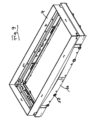
- Figure 1 shows a perspective view of a shaft, the shaft walls of which consist of three wall elements 1 placed one on top of the other.
- the upper end of the shaft is formed by a head frame 2 and a steel frame 3 arranged above it, on which a circumferential flat steel 4 is fastened, in which two shaft covers 5 are arranged flush.
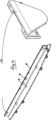
- Figure 2 shows the complete head frame 2, which is attached to the top of two wall elements 1 of different heights.
- the head frame 2 consists of four head frame parts 6, which are joined together at the corners of the rectangular shaft.
- the head frame parts 6 consist of an essentially plate-shaped section 7, which rests on the associated shaft wall, and a formwork section 8 which is angled upwards at a right angle and which faces the inside of the shaft.
- recesses 9 are formed into which locking bolts, not shown, of the manhole covers can enter.
- the recesses 9 can be releasably closed by plugged-on closure plates 10, which are in Figure 4 are shown.
- a head frame part 6 which can be attached to the top of a shaft wall without the use of tools.
- the head frame part 6 is provided with hooks 11 and locking lugs 12.
- the hooks 11 form clamping means which are inserted into the shaft wall from the outside of the shaft in order to initially position the head frame part 6 correctly on the top of the shaft wall.
- the locking lugs 12 engage on the inside in recesses in the shaft wall, with this locking of the head frame part 6 or the entire head frame 2 being fixed immovably on the shaft wall.
- Figure 5 A shows a perspective view of a hook 11.
- the Figures 5 C and 5 D ensure the insertion of the head frame part provided with the hook 11 6 under the upper wall of the wall element 1 for positioning the head frame part 6 on the shaft wall.
- Figure 5B shows the position of two hooks 11 on the shaft wall 1.
- Figure 6 shows a locking lug 12 on the underside of the head frame part 6 on its inner edge area.
- Figure 7 is a vertical section through the upper end area of the shaft.
- An end cap 13 is inserted into the steel frame 3 at each corner area, which contains a downwardly extendable spindle 14 which is supported on a support plate 15 when the spindle 14 is extended downwards in order to achieve height compensation ( Figures 8A and 8B ).
- the steel frame 3 which stands on four spindles, to have the required stability, the steel frame must be lined with a flowable mortar that fills the entire free space under the steel frame 3.
- the inner formwork section 8 prevents the liquid mortar from draining into the interior of the shaft.
- a circumferential outer shell 16 is attached to the outside of the wall element 1 with clips 17, as Figure 9 shows.
Landscapes
- Engineering & Computer Science (AREA)
- Environmental & Geological Engineering (AREA)
- Life Sciences & Earth Sciences (AREA)
- General Life Sciences & Earth Sciences (AREA)
- Mining & Mineral Resources (AREA)
- Paleontology (AREA)
- Civil Engineering (AREA)
- General Engineering & Computer Science (AREA)
- Structural Engineering (AREA)
- Forms Removed On Construction Sites Or Auxiliary Members Thereof (AREA)
Abstract
Description
- Die Erfindung betrifft einen Schacht, dessen Schachtwände aus aufeinander aufgesetzten Wandelementen bestehen, die im Spritzgussverfahren hergestellt sind. Meist werden zwei oder drei Reihen von Wandelementen übereinander angeordnet, wobei der obere Abschluss der so gebildeten Schachtwände einen Stahlrahmen aus einem umlaufenden Rechteckprofil aufweist, auf dem ein oder mehrere Schachtdeckel angeordnet werden, die von einem außen an dem Stahlrahmen befestigten Flachstahl umgeben sind. Die Oberkante des Flachstahls und die Oberseite des oder der Schachtdeckel müssen auf derselben Höhe wie die Umgebung des Schachtes liegen. Hierzu ist es bekannt, dass sich der Stahlrahmen auf Spindeln abstützen kann, deren Länge so eingestellt wird, dass der oder die Schachtdeckel auf Umgebungsniveau liegen.
- Da der oder die Schachtdeckel je nach Einbauort großen mechanischen Belastungen aus Kraftfahrzeugverkehr ausgesetzt sein können, muss der obere Abschluss des Schachtes eine ausreichend große Stabilität aufweisen.
- Der vorliegenden Erfindung liegt die Aufgabe zugrunde, einen Schacht anzugeben, bei dem der obere Abschluss schnell und einfach zu montieren ist. Diese Aufgabe wird erfindungsgemäß durch die Merkmale des Patentanspruchs 1 gelöst.
- Vorteilhafte Ausgestaltungen der Erfindung sind in den Unteransprüchen gekennzeichnet.
- Die Erfindung sieht vor, dass auf der Oberseite der Schachtwände ein Kopfrahmen aufliegt, der durch Klemm-Mittel und/oder Rastmittel auf den Schachtwänden fixiert ist, und dass der Stahlrahmen entweder direkt auf dem Kopfrahmen oder auf einer auf dem Kopfrahmen angeordneten, unterfütternden Mörtelschicht aufliegt. Bei dieser Ausbildung ist der Kopfrahmen ohne Zuhilfenahme von Werkzeugen auf einfache Weise zu montieren, wobei dennoch gewährleistet ist, dass der Kopfrahmen bei allen auftretenden Belastungen unverschieblich auf den Schachtwänden gehalten ist. Der Stahlrahmen liegt dabei entweder auf dem Kopfrahmen auf oder auf einer auf dem Kopfrahmen angeordneten, unterfütternden Mörtelschicht, wenn der Stahlrahmen mit Hilfe von ausgefahrenen Spindeln angehoben ist.
- Der Kopfrahmen ist bevorzugt im Spritzgussverfahren aus Kunststoff, vorzugsweise aus PC, hergestellt.
- Des weiteren ist vorgesehen, dass der Kopfrahmen aus mehreren Kopfrahmenteilen zusammengesetzt ist. Wenn - wie dies bevorzugt ist - der Schacht eine rechteckige Form hat, besteht der Kopfrahmen aus vier Kopfrahmenteilen, die an den Ecken des Schachtes aneinander anliegen oder ineinander eingreifen, nachdem die Kopfrahmenteile auf den Schachtwänden befestigt sind.
- Hierzu wird mit besonderem Vorteil vorgeschlagen, dass die Kopfrahmenteile an einem seitlichen Randabschnitt, bevorzugt an dem äußeren Randabschnitt, als Klemm-Mittel Haken aufweisen, die in die Schachtwände eingeschoben werden, um den Kopfrahmen auf den Schachtwänden zu positionieren. Die Haken können einstückig mit den Kopfrahmenteilen ausgebildet oder auf jede zweckmäßige Weise an den Kopfrahmenteilen kraftschlüssig befestigt sein. Die auf diese Weise positionierten Kopfrahmenteile sind an den Ecken zu einem geschlossenen Kopfrahmen zusammengesetzt.
- Nach einem weiteren Vorschlag haben die Kopfrahmenteile an den gegenüber liegenden seitlichen Rändern Rastnasen, die in Aussparungen der Schachtwände einrasten, um den Kopfrahmen auf den Schachtwänden zu fixieren.
- Die werkzeuglose Befestigung des Kopfrahmens auf der Oberseite der Schachtwände ist auch von einem ungeübten Monteur schnell und einfach auszuführen.
- Nach einem weiteren Vorschlag der Erfindung besteht der Kopfrahmen aus einem plattenförmigen Abschnitt, der auf den Schachtwänden aufliegt, und einem in der Einbaulage nach oben abgewinkelten Schalungsabschnitt, der an der Innenseite der Schachtwände angeordnet wird. Der Schalungsabschnitt schließt zweckmäßigerweise im rechten Winkel an den plattenförmigen Abschnitt an. Mit dieser Ausbildung wird erreicht, dass zum Unterfüttern des auf ausgefahrenen Spindeln stehenden Stahlrahmen nur eine geringe Menge Vergussmörtel benötigt wird, da der auf den Kopfrahmen aufgebrachte dünnflüssige Mörtel nicht zur Innenseite des Schachtes abfließen kann. Diese vorteilhafte Wirkung kann auch dadurch erhöht werden, dass nach einem weiteren Vorschlag auch an der Außenseite der Schachtwand eine Schalungswand angebracht wird. Diese kann mit Clipsen an der Schachtwand befestigt werden, so dass die Außenschalung nach erfolgtem Verguss wieder abgenommen werden kann.
- Am oberen Rand des Schalungsabschnitts des Kopfrahmens sind zweckmäßigerweise Ausschnitte ausgebildet, in die Verriegelungsbolzen des oder der Deckel eintreten können, um die Einbaulage der Deckel zu sichern. Diese Ausschnitte können durch aufgeschobene Verschlussplatten überdeckt werden, die einen unerwünschten Austritt von Vergussmörtel aus den Ausschnitten verhindern.
- Außerdem wird vorgeschlagen, dass der Kopfrahmen vorzugsweise an jedem Eckbereich eine Einsenkung zur Aufnahme eines Auflageblechs aufweist, und dass in dem Stahlrahmen an entsprechenden Stellen die Spindeln angeordnet sind, die zum Höhenausgleich des Stahlrahmens auf das Umgebungsniveau ausfahrbar sind und sich dabei auf den Auflageblechen abstützen.
- Weitere Einzelheiten der Erfindung ergeben sich aus der nachfolgenden Beschreibung einer bevorzugten Ausführungsform sowie anhand der Zeichnungen. Dabei zeigen:
- Figur 1
- eine perspektivische Ansicht eines kompletten Schachtes;
- Figur 2
- zwei Darstellungen der Montage eines Kopfrahmens;
- Figur 3
- ein Kopfrahmenteil mit Haken zur Positionierung und Rastnasen zur Fixierung;
- Figur 4
- die Montage von Verschlussplatten;
- Figuren 5A bis 5D
- Haken zur Positionierung des Kopfrahmens in einer perspektivischen Ansicht und bei der Befestigung des Kopfrahmens;
- Figur 6A und 6B
- einen Vertikalschnitt durch den Kopfrahmen mit einer Rastnase vor und nach der Befestigung des Kopfrahmens;
- Figur 7
- eine Schnittdarstellung des oberen Abschlusses eines Schachtes;
- Figuren 8A und 8B
- die Montage der Endkappen und eine vergrößerte Darstellung einer solchen;
- Figur 9
- die Anbringung einer Außenschalung am oberen Rand der Schachtwand.
-
Figur 1 zeigt eine perspektivische Ansicht eines Schachtes, dessen Schachtwände aus drei aufeinandergesetzten Wandelementen 1 bestehen. Den oberen Abschluss des Schachtes bilden ein Kopfrahmen 2 und ein darüber angeordneter Stahlrahmen 3, auf dem ein umlaufender Flachstahl 4 befestigt ist, in dem zwei Schachtdeckel 5 bündig angeordnet sind. -
Figur 2 zeigt den vollständigen Kopfrahmen 2, der auf der Oberseite von zwei Wandelementen 1 unterschiedlicher Höhe befestigt ist. Der Kopfrahmen 2 besteht aus vier Kopfrahmenteilen 6, die an den Ecken des rechteckigen Schachtes zusammengefügt sind. Die Kopfrahmenteile 6 bestehen aus einem im wesentlichen plattenförmigen Abschnitt 7, der auf der zugehörigen Schachtwand aufliegt, und einem rechtwinklig nach oben abgewinkelten Schalungsabschnitt 8, der der Innenseite des Schachtes zugewandt ist. In dem oberen Randbereich der Schalungsabschnitte 8 sind Aussparungen 9 ausgebildet, in die nicht dargestellte Verrieglungsbolzen der Schachtdeckel eintreten können. Die Aussparungen 9 sind durch aufgesteckte Verschlussplatten 10 lösbar verschließbar, die inFigur 4 abgebildet sind. - In
Figur 3 ist ein Kopfrahmenteil 6 abgebildet, der ohne Zuhilfenahme von Werkzeugen auf der Oberseite einer Schachtwand befestigbar ist. Hierzu ist der Kopfrahmenteil 6 mit Haken 11 und Rastnasen 12 versehen. Die Haken 11 bilden Klemm-Mittel, die von der Außenseite des Schachtes aus in die Schachtwand eingeschoben werden, um den Kopfrahmenteil 6 zunächst korrekt auf der Oberseite der Schachtwand zu positionieren. Die Rastnasen 12 greifen an der Innenseite in Aussparungen der Schachtwand ein, wobei durch diese Verrastung des Kopfrahmenteils 6 bzw. der gesamte Kopfrahmen 2 unverschieblich auf der Schachtwand fixiert ist. -
Figur 5 A zeigt eine perspektivische Ansicht eines Hakens 11. DieFiguren 5 C und 5 D stellen das Einschieben des mit dem Haken 11 versehenen Kopfrahmenteils 6 unter die obere Wand des Wandelements 1 zur Positionierung des Kopfrahmenteils 6 auf der Schachtwand dar.Figur 5B zeigt die Position zweier Haken 11 an der Schachtwand 1. -
Figur 6 zeigt eine Rastnase 12 an der Unterseite des Kopfrahmenteils 6 an dessen inneren Randbereich. Wenn die Rastnase 12 in eine entsprechende Aussparung in der Oberseite des Wandelements 1 eingerastet ist, ist der Kopfrahmenteil 6 bzw. der gesamte, zusammengesetzte Kopfrahmen 2 auf der Oberseite des Wandelements 1 unverschieblich fixiert. -
Figur 7 ist ein Vertikalschnitt durch den oberen Abschlussbereich des Schachtes. In den Stahlrahmen 3 ist an jedem Eckbereich eine Endkappe 13 eingesetzt, die eine nach unten ausfahrbare Spindel 14 enthält, die sich auf einem Auflageblech 15 aufstützt, wenn die Spindel 14 nach unten ausgefahren ist, um den Höhenausgleich hervorzurufen (Figuren 8A und 8B ). Damit der auf vier Spindeln stehende Stahlrahmen 3 die erforderliche Stabilität erhält, muss der Stahlrahmen mit einem fließfähigen Mörtel unterfüttert werden, der den gesamten Freiraum unter dem Stahlrahmen 3 ausfüllt. Der innere Schalungsabschnitt 8 verhindert dabei, dass der flüssige Mörtel ins Innere des Schachtes abläuft. Um dies auch an der Außenseite des Schachtes zu vermeiden, wird an der Außenseite des Wandelements 1 eine umlaufende Außenschale 16 mit Clipsen 17 befestigt, wieFigur 9 zeigt.
Claims (8)
- Schacht, der aus mehreren aus Kunststoff bestehenden Schachtwänden (1) zusammengesetzt ist, deren oberer Abschluss einen Stahlrahmen (3) aufweist, auf dem ein oder mehrere Schachtdeckel (5) angeordnet werden,
dadurch gekennzeichnet,dass auf der Oberseite der Schachtwände (1) ein Kopfrahmen (2) aufliegt, der durch Klemm-Mittel und/oder Rastmittel auf den Schachtwänden (1) fixiert ist, unddass der Stahlrahmen (3) entweder direkt auf dem Kopfrahmen (2) oder auf einer auf dem Kopfrahmen angeordneten, unterfütternden Mörtelschicht aufliegt. - Schacht nach Anspruch 1,
dadurch gekennzeichnet,
dass der Kopfrahmen (2) aus mehreren Kopfrahmenteilen (6) zusammengesetzt ist. - Schacht nach Anspruch 1 oder 2,
dadurch gekennzeichnet,
dass die Kopfrahmenteile (6) an einem seitlichen Randabschnitt als Klemm-Mittel Haken (11) aufweisen, die in die Schachtwände (1) eingeschoben werden, um die Kopfrahmenteile (6) auf den Schachtwänden (1) zu positionieren. - Schacht nach einem der Ansprüche 1 bis 3,
dadurch gekennzeichnet,
dass die Kopfrahmenteile (6) an dem gegenüberliegenden seitlichen Rand Rastnasen (12) aufweisen, die in Aussparungen der Schachtwände (1) einrasten, um den Kopfrahmen (2) zu fixieren. - Schacht nach einem der Ansprüche 1 bis 4,
dadurch gekennzeichnet,
dass der Kopfrahmen (2) einen plattenförmigen Abschnitt (7), der auf den Schachtwänden (1) aufliegt, und einen in der Einbaulage nach oben abgewinkelten Schalungsabschnitt (8) aufweist, der in der Einbaulage an der Innenseite der Schachtwände (1) angeordnet ist. - Schacht nach einem der Ansprüche 1 bis 5,
dadurch gekennzeichnet,dass der Kopfrahmen (2) vorzugsweise an jedem Eckbereich eine Aufnahme (18) für ein Auflageblech (15) aufweist, unddass in dem Stahlrahmen (4) an entsprechenden Stellen Spindeln (14) angeordnet sind, die zum Höhenausgleich des Stahlrahmens (4) auf das Umgebungsniveau ausfahrbar sind und sich dabei auf den Auflageblechen abstützen. - Schacht nach einem der Ansprüche 1 bis 6,
dadurch gekennzeichnet,
dass am oberen Rand des Schalungsabschnitts (8) des Kopfrahmens (2) Ausschnitte (9) ausgebildet sind, die durch lösbar aufgeschobene Verschlussplatten (10) überdeckbar sind. - Schacht nach einem der Ansprüche 1 bis 7,
dadurch gekennzeichnet,
dass eine umlaufende Außenschalung (16) mit Clipsen (17) an der Schachtwand (1) anbringbar ist.
Applications Claiming Priority (1)
| Application Number | Priority Date | Filing Date | Title |
|---|---|---|---|
| DE102022114116.0A DE102022114116A1 (de) | 2022-06-03 | 2022-06-03 | Schacht |
Publications (2)
| Publication Number | Publication Date |
|---|---|
| EP4286595A1 true EP4286595A1 (de) | 2023-12-06 |
| EP4286595B1 EP4286595B1 (de) | 2025-07-16 |
Family
ID=85979670
Family Applications (1)
| Application Number | Title | Priority Date | Filing Date |
|---|---|---|---|
| EP23166711.4A Active EP4286595B1 (de) | 2022-06-03 | 2023-04-05 | Schacht |
Country Status (4)
| Country | Link |
|---|---|
| EP (1) | EP4286595B1 (de) |
| DE (1) | DE102022114116A1 (de) |
| DK (1) | DK4286595T3 (de) |
| PL (1) | PL4286595T3 (de) |
Citations (4)
| Publication number | Priority date | Publication date | Assignee | Title |
|---|---|---|---|---|
| DE10314897B3 (de) * | 2003-04-01 | 2004-10-14 | Lic Langmatz Gmbh | System zur Unterbringung von Verteilereinrichtungen von Kupfer- und/oder Glasfaserkabeln |
| EP1587199A1 (de) * | 2004-04-16 | 2005-10-19 | LIC Langmatz GmbH | System zur Unterbringung von Verteilereinrichtungen von Kupfer- und/oder Glasfaserkabeln |
| DE202007014465U1 (de) * | 2007-10-16 | 2007-12-20 | Frei Netzwerk Ausstattung Gmbh | Unterflurschacht |
| DE102011116874A1 (de) * | 2011-10-25 | 2013-04-25 | Langmatz Gmbh | Schacht |
-
2022
- 2022-06-03 DE DE102022114116.0A patent/DE102022114116A1/de active Pending
-
2023
- 2023-04-05 PL PL23166711.4T patent/PL4286595T3/pl unknown
- 2023-04-05 EP EP23166711.4A patent/EP4286595B1/de active Active
- 2023-04-05 DK DK23166711.4T patent/DK4286595T3/da active
Patent Citations (4)
| Publication number | Priority date | Publication date | Assignee | Title |
|---|---|---|---|---|
| DE10314897B3 (de) * | 2003-04-01 | 2004-10-14 | Lic Langmatz Gmbh | System zur Unterbringung von Verteilereinrichtungen von Kupfer- und/oder Glasfaserkabeln |
| EP1587199A1 (de) * | 2004-04-16 | 2005-10-19 | LIC Langmatz GmbH | System zur Unterbringung von Verteilereinrichtungen von Kupfer- und/oder Glasfaserkabeln |
| DE202007014465U1 (de) * | 2007-10-16 | 2007-12-20 | Frei Netzwerk Ausstattung Gmbh | Unterflurschacht |
| DE102011116874A1 (de) * | 2011-10-25 | 2013-04-25 | Langmatz Gmbh | Schacht |
Also Published As
| Publication number | Publication date |
|---|---|
| EP4286595B1 (de) | 2025-07-16 |
| DE102022114116A1 (de) | 2023-12-14 |
| DK4286595T3 (da) | 2025-10-06 |
| PL4286595T3 (pl) | 2025-11-12 |
Similar Documents
| Publication | Publication Date | Title |
|---|---|---|
| EP1064707A1 (de) | Rahmengestell für einen schaltschrank | |
| EP2669451A2 (de) | Tragkonstruktion und Verfahren zur Montage einer Tragkonstruktion | |
| DE60021872T2 (de) | Befestigungs- und schaniervorrichtung für ein paneel und damit ausgestattetes paneelsystem | |
| EP1811624B1 (de) | Bodeneinbaukassette für elektrische Installationsgeräte | |
| DE2249483C3 (de) | Einbauvorrichtung zur Befestigung eines Einbauelements wie einer Einbauspüle in einem Ausschnitt einer Platte | |
| DE4021332A1 (de) | Kanalelement aus stahlbeton | |
| EP3643868A1 (de) | Glasträgerkonstruktion und rahmenkonstruktion | |
| EP4286595B1 (de) | Schacht | |
| DE8915993U1 (de) | Stütze für einen Doppelboden | |
| EP1617010B1 (de) | Lichtschacht mit Aufsatz | |
| DE19856689A1 (de) | Entwässerungsrinne | |
| DE102017120641A1 (de) | Installation einer Sanitärwanne auf einem Traggestell und Verfahren zur Montage | |
| EP4286596B1 (de) | Schacht | |
| DE3632726C2 (de) | Rechteckiger Rahmen für Schachtabdeckungen | |
| DE9308108U1 (de) | Schranksockel | |
| EP0786846B1 (de) | Elektroinstallationskanal | |
| DE2650180B2 (de) | Steigeisen | |
| EP4693775A1 (de) | Modularer eingrabsockel und modularer verteilerkasten | |
| DE102024122555A1 (de) | Modularer Eingrabsockel und modularer Verteilerkasten | |
| EP1352456B1 (de) | Gehäuse, insbesondere für den einbau elektrischer und elektronischer bauteile | |
| DE29510748U1 (de) | Säule | |
| AT520870B1 (de) | Modulare Abdeckung für Lichtschächte, mit der Möglichkeit unterschiedliche Designs darzustellen | |
| DE102019106003C5 (de) | Waschtisch | |
| DE1759533B1 (de) | Stahlbetongehaeuse fuer grossvolumige,fahrbare Muellbehaelter | |
| EP0194595A2 (de) | Sockel zur Montage eines Lüftungsgerätes auf einem Dach |
Legal Events
| Date | Code | Title | Description |
|---|---|---|---|
| PUAI | Public reference made under article 153(3) epc to a published international application that has entered the european phase |
Free format text: ORIGINAL CODE: 0009012 |
|
| STAA | Information on the status of an ep patent application or granted ep patent |
Free format text: STATUS: THE APPLICATION HAS BEEN PUBLISHED |
|
| AK | Designated contracting states |
Kind code of ref document: A1 Designated state(s): AL AT BE BG CH CY CZ DE DK EE ES FI FR GB GR HR HU IE IS IT LI LT LU LV MC ME MK MT NL NO PL PT RO RS SE SI SK SM TR |
|
| P01 | Opt-out of the competence of the unified patent court (upc) registered |
Effective date: 20231208 |
|
| STAA | Information on the status of an ep patent application or granted ep patent |
Free format text: STATUS: REQUEST FOR EXAMINATION WAS MADE |
|
| 17P | Request for examination filed |
Effective date: 20240207 |
|
| RBV | Designated contracting states (corrected) |
Designated state(s): AL AT BE BG CH CY CZ DE DK EE ES FI FR GB GR HR HU IE IS IT LI LT LU LV MC ME MK MT NL NO PL PT RO RS SE SI SK SM TR |
|
| GRAP | Despatch of communication of intention to grant a patent |
Free format text: ORIGINAL CODE: EPIDOSNIGR1 |
|
| STAA | Information on the status of an ep patent application or granted ep patent |
Free format text: STATUS: GRANT OF PATENT IS INTENDED |
|
| INTG | Intention to grant announced |
Effective date: 20250409 |
|
| GRAS | Grant fee paid |
Free format text: ORIGINAL CODE: EPIDOSNIGR3 |
|
| GRAA | (expected) grant |
Free format text: ORIGINAL CODE: 0009210 |
|
| STAA | Information on the status of an ep patent application or granted ep patent |
Free format text: STATUS: THE PATENT HAS BEEN GRANTED |
|
| AK | Designated contracting states |
Kind code of ref document: B1 Designated state(s): AL AT BE BG CH CY CZ DE DK EE ES FI FR GB GR HR HU IE IS IT LI LT LU LV MC ME MK MT NL NO PL PT RO RS SE SI SK SM TR |
|
| REG | Reference to a national code |
Ref country code: GB Ref legal event code: FG4D Free format text: NOT ENGLISH |
|
| REG | Reference to a national code |
Ref country code: CH Ref legal event code: EP |
|
| REG | Reference to a national code |
Ref country code: DE Ref legal event code: R096 Ref document number: 502023001338 Country of ref document: DE |
|
| REG | Reference to a national code |
Ref country code: IE Ref legal event code: FG4D Free format text: LANGUAGE OF EP DOCUMENT: GERMAN |
|
| REG | Reference to a national code |
Ref country code: DK Ref legal event code: T3 Effective date: 20251001 |
|
| REG | Reference to a national code |
Ref country code: NL Ref legal event code: MP Effective date: 20250716 |
|
| PG25 | Lapsed in a contracting state [announced via postgrant information from national office to epo] |
Ref country code: PT Free format text: LAPSE BECAUSE OF FAILURE TO SUBMIT A TRANSLATION OF THE DESCRIPTION OR TO PAY THE FEE WITHIN THE PRESCRIBED TIME-LIMIT Effective date: 20251117 |
|
| PG25 | Lapsed in a contracting state [announced via postgrant information from national office to epo] |
Ref country code: NL Free format text: LAPSE BECAUSE OF FAILURE TO SUBMIT A TRANSLATION OF THE DESCRIPTION OR TO PAY THE FEE WITHIN THE PRESCRIBED TIME-LIMIT Effective date: 20250716 |
|
| PG25 | Lapsed in a contracting state [announced via postgrant information from national office to epo] |
Ref country code: IS Free format text: LAPSE BECAUSE OF FAILURE TO SUBMIT A TRANSLATION OF THE DESCRIPTION OR TO PAY THE FEE WITHIN THE PRESCRIBED TIME-LIMIT Effective date: 20251116 |
|
| PG25 | Lapsed in a contracting state [announced via postgrant information from national office to epo] |
Ref country code: NO Free format text: LAPSE BECAUSE OF FAILURE TO SUBMIT A TRANSLATION OF THE DESCRIPTION OR TO PAY THE FEE WITHIN THE PRESCRIBED TIME-LIMIT Effective date: 20251016 |
|
| REG | Reference to a national code |
Ref country code: LT Ref legal event code: MG9D |
|
| PG25 | Lapsed in a contracting state [announced via postgrant information from national office to epo] |
Ref country code: FI Free format text: LAPSE BECAUSE OF FAILURE TO SUBMIT A TRANSLATION OF THE DESCRIPTION OR TO PAY THE FEE WITHIN THE PRESCRIBED TIME-LIMIT Effective date: 20250716 |
|
| PG25 | Lapsed in a contracting state [announced via postgrant information from national office to epo] |
Ref country code: HR Free format text: LAPSE BECAUSE OF FAILURE TO SUBMIT A TRANSLATION OF THE DESCRIPTION OR TO PAY THE FEE WITHIN THE PRESCRIBED TIME-LIMIT Effective date: 20250716 |
|
| PG25 | Lapsed in a contracting state [announced via postgrant information from national office to epo] |
Ref country code: GR Free format text: LAPSE BECAUSE OF FAILURE TO SUBMIT A TRANSLATION OF THE DESCRIPTION OR TO PAY THE FEE WITHIN THE PRESCRIBED TIME-LIMIT Effective date: 20251017 |
|
| PG25 | Lapsed in a contracting state [announced via postgrant information from national office to epo] |
Ref country code: SE Free format text: LAPSE BECAUSE OF FAILURE TO SUBMIT A TRANSLATION OF THE DESCRIPTION OR TO PAY THE FEE WITHIN THE PRESCRIBED TIME-LIMIT Effective date: 20250716 |
|
| PG25 | Lapsed in a contracting state [announced via postgrant information from national office to epo] |
Ref country code: LV Free format text: LAPSE BECAUSE OF FAILURE TO SUBMIT A TRANSLATION OF THE DESCRIPTION OR TO PAY THE FEE WITHIN THE PRESCRIBED TIME-LIMIT Effective date: 20250716 |
|
| PG25 | Lapsed in a contracting state [announced via postgrant information from national office to epo] |
Ref country code: BG Free format text: LAPSE BECAUSE OF FAILURE TO SUBMIT A TRANSLATION OF THE DESCRIPTION OR TO PAY THE FEE WITHIN THE PRESCRIBED TIME-LIMIT Effective date: 20250716 |
|
| PG25 | Lapsed in a contracting state [announced via postgrant information from national office to epo] |
Ref country code: RS Free format text: LAPSE BECAUSE OF FAILURE TO SUBMIT A TRANSLATION OF THE DESCRIPTION OR TO PAY THE FEE WITHIN THE PRESCRIBED TIME-LIMIT Effective date: 20251016 |
|
| PG25 | Lapsed in a contracting state [announced via postgrant information from national office to epo] |
Ref country code: ES Free format text: LAPSE BECAUSE OF FAILURE TO SUBMIT A TRANSLATION OF THE DESCRIPTION OR TO PAY THE FEE WITHIN THE PRESCRIBED TIME-LIMIT Effective date: 20250716 |
|
| PG25 | Lapsed in a contracting state [announced via postgrant information from national office to epo] |
Ref country code: SM Free format text: LAPSE BECAUSE OF FAILURE TO SUBMIT A TRANSLATION OF THE DESCRIPTION OR TO PAY THE FEE WITHIN THE PRESCRIBED TIME-LIMIT Effective date: 20250716 |
|
| PG25 | Lapsed in a contracting state [announced via postgrant information from national office to epo] |
Ref country code: IT Free format text: LAPSE BECAUSE OF FAILURE TO SUBMIT A TRANSLATION OF THE DESCRIPTION OR TO PAY THE FEE WITHIN THE PRESCRIBED TIME-LIMIT Effective date: 20250716 |
|
| PG25 | Lapsed in a contracting state [announced via postgrant information from national office to epo] |
Ref country code: CZ Free format text: LAPSE BECAUSE OF FAILURE TO SUBMIT A TRANSLATION OF THE DESCRIPTION OR TO PAY THE FEE WITHIN THE PRESCRIBED TIME-LIMIT Effective date: 20250716 |
|
| PGFP | Annual fee paid to national office [announced via postgrant information from national office to epo] |
Ref country code: PL Payment date: 20260331 Year of fee payment: 4 |
|
| PG25 | Lapsed in a contracting state [announced via postgrant information from national office to epo] |
Ref country code: SK Free format text: LAPSE BECAUSE OF FAILURE TO SUBMIT A TRANSLATION OF THE DESCRIPTION OR TO PAY THE FEE WITHIN THE PRESCRIBED TIME-LIMIT Effective date: 20250716 Ref country code: EE Free format text: LAPSE BECAUSE OF FAILURE TO SUBMIT A TRANSLATION OF THE DESCRIPTION OR TO PAY THE FEE WITHIN THE PRESCRIBED TIME-LIMIT Effective date: 20250716 |