EP4286509A1 - Nukleinsäurenachweisvorrichtung und nukleinsäurenachweisverfahren - Google Patents
Nukleinsäurenachweisvorrichtung und nukleinsäurenachweisverfahren Download PDFInfo
- Publication number
- EP4286509A1 EP4286509A1 EP23754691.6A EP23754691A EP4286509A1 EP 4286509 A1 EP4286509 A1 EP 4286509A1 EP 23754691 A EP23754691 A EP 23754691A EP 4286509 A1 EP4286509 A1 EP 4286509A1
- Authority
- EP
- European Patent Office
- Prior art keywords
- chamber
- sample
- reaction
- sub
- nucleic acid
- Prior art date
- Legal status (The legal status is an assumption and is not a legal conclusion. Google has not performed a legal analysis and makes no representation as to the accuracy of the status listed.)
- Pending
Links
Images


Classifications
-
- C—CHEMISTRY; METALLURGY
- C12—BIOCHEMISTRY; BEER; SPIRITS; WINE; VINEGAR; MICROBIOLOGY; ENZYMOLOGY; MUTATION OR GENETIC ENGINEERING
- C12Q—MEASURING OR TESTING PROCESSES INVOLVING ENZYMES, NUCLEIC ACIDS OR MICROORGANISMS; COMPOSITIONS OR TEST PAPERS THEREFOR; PROCESSES OF PREPARING SUCH COMPOSITIONS; CONDITION-RESPONSIVE CONTROL IN MICROBIOLOGICAL OR ENZYMOLOGICAL PROCESSES
- C12Q1/00—Measuring or testing processes involving enzymes, nucleic acids or microorganisms; Compositions therefor; Processes of preparing such compositions
- C12Q1/68—Measuring or testing processes involving enzymes, nucleic acids or microorganisms; Compositions therefor; Processes of preparing such compositions involving nucleic acids
- C12Q1/6844—Nucleic acid amplification reactions
-
- B—PERFORMING OPERATIONS; TRANSPORTING
- B01—PHYSICAL OR CHEMICAL PROCESSES OR APPARATUS IN GENERAL
- B01L—CHEMICAL OR PHYSICAL LABORATORY APPARATUS FOR GENERAL USE
- B01L3/00—Containers or dishes for laboratory use, e.g. laboratory glassware; Droppers
- B01L3/50—Containers for the purpose of retaining a material to be analysed, e.g. test tubes
- B01L3/502—Containers for the purpose of retaining a material to be analysed, e.g. test tubes with fluid transport, e.g. in multi-compartment structures
-
- B—PERFORMING OPERATIONS; TRANSPORTING
- B01—PHYSICAL OR CHEMICAL PROCESSES OR APPARATUS IN GENERAL
- B01L—CHEMICAL OR PHYSICAL LABORATORY APPARATUS FOR GENERAL USE
- B01L7/00—Heating or cooling apparatus; Heat insulating devices
- B01L7/52—Heating or cooling apparatus; Heat insulating devices with provision for submitting samples to a predetermined sequence of different temperatures, e.g. for treating nucleic acid samples
-
- B—PERFORMING OPERATIONS; TRANSPORTING
- B01—PHYSICAL OR CHEMICAL PROCESSES OR APPARATUS IN GENERAL
- B01L—CHEMICAL OR PHYSICAL LABORATORY APPARATUS FOR GENERAL USE
- B01L2200/00—Solutions for specific problems relating to chemical or physical laboratory apparatus
- B01L2200/06—Fluid handling related problems
- B01L2200/0689—Sealing
-
- B—PERFORMING OPERATIONS; TRANSPORTING
- B01—PHYSICAL OR CHEMICAL PROCESSES OR APPARATUS IN GENERAL
- B01L—CHEMICAL OR PHYSICAL LABORATORY APPARATUS FOR GENERAL USE
- B01L2200/00—Solutions for specific problems relating to chemical or physical laboratory apparatus
- B01L2200/16—Reagents, handling or storing thereof
-
- B—PERFORMING OPERATIONS; TRANSPORTING
- B01—PHYSICAL OR CHEMICAL PROCESSES OR APPARATUS IN GENERAL
- B01L—CHEMICAL OR PHYSICAL LABORATORY APPARATUS FOR GENERAL USE
- B01L2300/00—Additional constructional details
- B01L2300/08—Geometry, shape and general structure
- B01L2300/0861—Configuration of multiple channels and/or chambers in a single devices
- B01L2300/0864—Configuration of multiple channels and/or chambers in a single devices comprising only one inlet and multiple receiving wells, e.g. for separation, splitting
-
- B—PERFORMING OPERATIONS; TRANSPORTING
- B01—PHYSICAL OR CHEMICAL PROCESSES OR APPARATUS IN GENERAL
- B01L—CHEMICAL OR PHYSICAL LABORATORY APPARATUS FOR GENERAL USE
- B01L2300/00—Additional constructional details
- B01L2300/08—Geometry, shape and general structure
- B01L2300/0861—Configuration of multiple channels and/or chambers in a single devices
- B01L2300/087—Multiple sequential chambers
-
- B—PERFORMING OPERATIONS; TRANSPORTING
- B01—PHYSICAL OR CHEMICAL PROCESSES OR APPARATUS IN GENERAL
- B01L—CHEMICAL OR PHYSICAL LABORATORY APPARATUS FOR GENERAL USE
- B01L2300/00—Additional constructional details
- B01L2300/08—Geometry, shape and general structure
- B01L2300/0861—Configuration of multiple channels and/or chambers in a single devices
- B01L2300/0877—Flow chambers
-
- B—PERFORMING OPERATIONS; TRANSPORTING
- B01—PHYSICAL OR CHEMICAL PROCESSES OR APPARATUS IN GENERAL
- B01L—CHEMICAL OR PHYSICAL LABORATORY APPARATUS FOR GENERAL USE
- B01L2300/00—Additional constructional details
- B01L2300/12—Specific details about materials
- B01L2300/123—Flexible; Elastomeric
-
- B—PERFORMING OPERATIONS; TRANSPORTING
- B01—PHYSICAL OR CHEMICAL PROCESSES OR APPARATUS IN GENERAL
- B01L—CHEMICAL OR PHYSICAL LABORATORY APPARATUS FOR GENERAL USE
- B01L2300/00—Additional constructional details
- B01L2300/16—Surface properties and coatings
- B01L2300/161—Control and use of surface tension forces, e.g. hydrophobic, hydrophilic
-
- B—PERFORMING OPERATIONS; TRANSPORTING
- B01—PHYSICAL OR CHEMICAL PROCESSES OR APPARATUS IN GENERAL
- B01L—CHEMICAL OR PHYSICAL LABORATORY APPARATUS FOR GENERAL USE
- B01L2300/00—Additional constructional details
- B01L2300/18—Means for temperature control
- B01L2300/1805—Conductive heating, heat from thermostatted solids is conducted to receptacles, e.g. heating plates, blocks
-
- B—PERFORMING OPERATIONS; TRANSPORTING
- B01—PHYSICAL OR CHEMICAL PROCESSES OR APPARATUS IN GENERAL
- B01L—CHEMICAL OR PHYSICAL LABORATORY APPARATUS FOR GENERAL USE
- B01L2400/00—Moving or stopping fluids
- B01L2400/04—Moving fluids with specific forces or mechanical means
- B01L2400/0475—Moving fluids with specific forces or mechanical means specific mechanical means and fluid pressure
- B01L2400/0478—Moving fluids with specific forces or mechanical means specific mechanical means and fluid pressure pistons
-
- B—PERFORMING OPERATIONS; TRANSPORTING
- B01—PHYSICAL OR CHEMICAL PROCESSES OR APPARATUS IN GENERAL
- B01L—CHEMICAL OR PHYSICAL LABORATORY APPARATUS FOR GENERAL USE
- B01L2400/00—Moving or stopping fluids
- B01L2400/06—Valves, specific forms thereof
- B01L2400/0605—Valves, specific forms thereof check valves
-
- B—PERFORMING OPERATIONS; TRANSPORTING
- B01—PHYSICAL OR CHEMICAL PROCESSES OR APPARATUS IN GENERAL
- B01L—CHEMICAL OR PHYSICAL LABORATORY APPARATUS FOR GENERAL USE
- B01L7/00—Heating or cooling apparatus; Heat insulating devices
Definitions
- the present disclosure generally relates to the field of medical diagnosis, in particular to nucleic acid detection devices and nucleic acid detection methods.
- Nucleic acid detection is a form medical detection methods for in-vitro diagnosis, and it enables the rapid detection of nucleic acids of pathogens in test samples.
- the nucleic acid detection is the most direct, reliable, and sensitive approach for rapid and specific detection of pathogens in an early stage, and has important applications in the fields of disease diagnosis, epidemic prevention and control, health monitoring, etc.
- the nucleic acid detection can provide information (e.g., a type, a concentration, etc.) about the pathogens, thereby avoiding interference from factors such as the disease infection window period, etc.
- nucleic acid detections usually utilize devices that are based on real-time fluorescence quantitative polymerase chain reaction (PCR) technology.
- PCR real-time fluorescence quantitative polymerase chain reaction
- the nucleic acid detection devices are often complex to control, take too long to be operational, and have strict requirements for operators and environments, thereby greatly limiting the groups of operators that are eligible to use the nucleic acid detection devices and the environments in which the nucleic acid detection devices can be used.
- the technical problems that urgently need to be solved in the field would include how to make the nucleic acid detection devices capable of easily and quickly detecting the nucleic acids of pathogens and how to improve the detection efficiency in the medical diagnosis process.
- the nucleic acid detection device may include a housing portion and a reaction portion.
- the housing portion may be configured to include a sample chamber, a first observation chamber, and a second observation chamber
- the reaction portion may be configured to include a first reaction chamber and a second reaction chamber.
- the sample chamber may communicate with the first reaction chamber, and the sample chamber may communicate with the second reaction chamber.
- the first observation chamber may communicate with the first reaction chamber, and the second observation chamber may communicate with the second reaction chamber.
- the nucleic acid detection method may include placing a sample into the sample chamber; making fluid containing the sample to enter the first reaction chamber through the first sample outlet, and making the fluid containing the sample to enter the second reaction chamber through the second sample outlet; making the sample to undergo a reverse transcription loop-mediated isothermal amplification reaction within the first reaction chamber to detect an internal standard gene of the sample, and making the sample to undergo a reverse transcription loop-mediated isothermal amplification reaction within the second reaction chamber to detect a target gene of the sample; making a first amplification reaction product generated after the reverse transcription loop-mediated isothermal amplification reaction occurs in the first reaction chamber to enter the first observation chamber, and making a second amplification reaction product generated after the reverse transcription loop-mediated isothermal amplification reaction occurs in the second reaction chamber to enter the second observation chamber; and determining a color of the first amplification reaction product
- 100 represents a nucleic acid detection device
- 110 represents a housing portion
- 120 represents a reaction portion
- 111 represents a sample chamber
- 111-1 represents a first sample outlet
- 111-2 represents a second sample outlet
- 111-3 represents a sample inlet
- 112 represents a piston chamber
- 1121 represents a fifth sub-chamber
- 1122 represents a sixth sub-chamber
- 112-1 represents a first opening
- 112-2 represents a second opening
- 113 represents a first observation chamber
- 114 represents a second observation chamber
- 113-1 represents a first inlet
- 113-2 represents a first observation port
- 114-1 represents a second inlet
- 114 -2 represents a second observation port
- 121 represents a first reaction chamber
- 122 represents a second reaction chamber
- 1211 represents a first sub-chamber
- 1212 represents a second sub-chamber
- 1212-1 represents a first portion
- 1212-2 represents a second portion
- 1221 represents a third sub
- first,” “second,” and similar words used in this description and the claims do not indicate any order, number, or importance, but are only used to distinguish different components.
- the terms “an,” “one,” and similar words do not indicate a numerical limitation, but indicate the presence of at least one.
- top,” “bottom,” and similar words are merely for illustrative purposes and are not restricted to a location or a spatial orientation.
- the terms “comprise” and “include” merely prompt to include steps and elements that have been clearly identified, and these steps and elements do not constitute an exclusive listing. The methods or devices may also include other steps or elements.
- a sample chamber of the nucleic acid detection device may be configured to receive and accommodate a sample.
- a first reaction chamber and a second reaction chamber may be configured to receive the sample within the sample chamber and make the sample to react (e.g., perform an amplification reaction), thereby achieving a nucleic acid detection of the sample (e.g., a detection of an internal standard gene and/or a detection of a target gene, etc.).
- a first observation chamber and a second observation chamber may be configured to observe fluid (e.g., an amplification reaction product) after the reaction within the first reaction chamber and the second reaction chamber.
- the first reaction chamber and the second reaction chamber may be configured to respectively perform the different types of nucleic acid detections on the sample at the same time.
- the first reaction chamber may be configured to detect the internal standard gene and the second reaction chamber may be configured to detect the target gene.
- the first reaction chamber and the second reaction chamber may be configured to make the sample to undergo different reactions at the same time so that different detections can be performed at the same time, while the first observation chamber and the second observation chamber may be configured to visually observe the fluid after the reactions occur in the first reaction chamber and the second reaction chamber, respectively, to obtain results of the nucleic acid detections, thereby improving the detection efficiency.
- nucleic acid detection device may be small in size, light in weight, and easy to operate, so that the nucleic acid detection device can easily and quickly achieve the nucleic acid detection of the sample.
- the nucleic acid detection device and the nucleic acid detection method of the present disclosure may be applied to perform the nucleic acid detection on viruses (e.g., novel coronavirus) and bacteria, etc.
- FIG. 1 is a schematic diagram illustrating an exemplary structure of a nucleic acid detection device according to some embodiments of the present disclosure.
- FIG. 2 is a schematic diagram illustrating an exemplary assembly of a nucleic acid detection device according to some embodiments of the present disclosure.
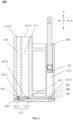
- FIG. 3 is a sectional view illustrating an exemplary nucleic acid detection device according to some embodiments of the present disclosure.
- a nucleic acid detection device 100 may include a housing portion 110 and a reaction portion 120.
- the housing portion 110 may be configured to include a sample chamber 111, a first observation chamber 113, and a second observation chamber 114.
- the reaction portion 120 may be configured to include a first reaction chamber 121 and a second reaction chamber 122.
- the sample chamber 111 may communicate with the first reaction chamber 121, and the sample chamber 111 may communicate with the second reaction chamber 122.
- the first observation chamber 113 may communicate with the first reaction chamber 121, and the second observation chamber 114 may communicate with the second reaction chamber 122.
- the reaction portion 120 may be located at a bottom portion of the housing portion 110. In some other embodiments, the reaction portion 120 may be located in other orientations of the housing portion 110, such as, a top portion, a side portion, etc.
- the sample chamber111 may be a columnar structure with a hollow interior.
- a top portion of the sample chamber 111 may be configured to include an opening (e.g., a sample inlet 111-3 as described below) for receiving a sample, and a bottom portion of the sample chamber 111 may also be configured to include one or more openings (e.g., a first sample outlet 111-1 and a second sample outlet 111-2 as described below) for communicating with the first reaction chamber 121 and the second reaction chamber 122.
- the sample chamber 111 may be used to accommodate the sample, such as, a swab-type sample, etc. The sample may be lysed and released in the sample chamber 111, so that a nucleic acid detection template may be obtained.
- a sample release agent may be also accommodated inside the sample chamber 111.
- the sample release agent may be used to make the sample in the sample chamber 111 to undergo the lysis and release to obtain the nucleic acid detection template.
- the sample release agent may be placed in the sample chamber 111 in advance and the sample may be lysed and released under the action of the sample release agent, so that the nucleic acid detection template of the sample may be obtained.
- a formula of the sample release agent may include a non-ionic surfactant of 0.2-2%, trehalose of 0.01-2%, potassium chloride of 50-200 mmol/L, ethylene diamine tetraacetic acid of 1-10 mmol/L, Tri-HCI of 0.2-5 mmol/L, or the like, or any combination thereof.
- the sample may undergo an amplification reaction (e.g., a reverse transcription loop-mediated isothermal amplification reaction) in the first reaction chamber 121 and the second reaction chamber 122 to achieve the nucleic acid detection of the sample.
- FIG. 5 is a bottom view illustrating a reaction portion according to some embodiments of the present disclosure. As shown in FIG. 2 and FIG. 5 , the first reaction chamber 121 and the second reaction chamber 122 may be disposed side by side on the reaction portion 120, and the first reaction chamber 121 may not communicate with the second reaction chamber 122. For example, the first reaction chamber 121 and the second reaction chamber 122 may be groove structures disposed side by side on the reaction portion 120.
- a reaction reagent may be placed in the first reaction chamber 121 and the second reaction chamber 122 in advance.
- a loop-mediated isothermal amplification reaction solution for housekeeping genes e.g., a RnaseP gene loop-mediated isothermal amplification reaction solution
- a loop-mediated isothermal amplification reaction solution for housekeeping genes may be placed in the first reaction chamber 121 to make the sample to undergo the reverse transcription loop-mediated isothermal amplification reaction in the first reaction chamber 121 so as to detect an internal standard gene of the sample.
- a formula of the reaction reagent may be selected as Bst DNA polymerase of 2-10 U, 2.5 ⁇ L of 10 x Bst Buffer, 0.5-3 ⁇ L of 10 x RnaseP Primers, 20-30 ⁇ L of template DNA, betaine of 0.1-10 mg/mL, Mg 2 SO 4 of 2-10 mM, calcein of 0.01%-0.5%, etc.
- a loop-mediated isothermal amplification reaction reagent e.g., a novel coronavirus gene loop-mediated isothermal amplification reaction reagent
- a loop-mediated isothermal amplification reaction reagent for viruses or bacteria to be detected may be placed in the second reaction chamber 122 to make the sample to undergo the reverse transcription loop-mediated isothermal amplification reaction in the second reaction chamber 122 so as to detect a target gene of the sample.
- a formula of the reaction reagent may be selected as Bst DNA polymerase of 2-10 U, 2.5 ⁇ L of 10 x Bst Buffer, 0.5-3 ⁇ L of 10 x Covid-19 Primers, 20-30 ⁇ L of template DNA, betaine of 0.1-10 mg/mL, Mg 2 SO 4 of 2-10 mM, calcein of 0.01 %-0.5%, etc.
- colors of first amplification reaction products generated by the sample may be different.
- whether sampling succeeds or not and whether a detection reagent is in a normal response may be determined by observing the first amplification reaction product generated in the first reaction chamber 121 to determine the color of the first amplification reaction product generated in the first reaction chamber 121. For example, when the sample contains human-derived cells, the first amplification reaction product in the first reaction chamber 121 may be yellow (a positive result), indicating successful sampling and the normal response of the detection reagent. When the sample contains no human-derived cells, the first amplification reaction product in the first reaction chamber 121 may be pink (a negative result), indicating failed sampling or invalidation of the detection reagent.
- colors of a second amplification reaction product generated within the second reaction chamber 122 may be different when the detection of the target gene of the sample performed in the second reaction chamber 122 includes different detection results (e.g., a negative result or a positive result).
- results of the nucleic acid detection may be determined by observing the second amplification reaction product generated within the second reaction chamber 122 to determine the color of the second amplification reaction product generated within the second reaction chamber 122.
- the color of the second amplification reaction product in the second reaction chamber 122 may be yellow, indicating that the detection result is positive.
- the color of the second amplification reaction product in the second reaction chamber 122 may be pink, indicating that the detection result is negative.
- the detection result of the internal standard gene is positive (i.e., the detection result of the target gene is credible).
- the color of the second amplification reaction product may be further observed. If the color of the second amplification reaction product is pink, the detection result of the target gene may be negative. If the color of the second amplification reaction product is yellow, the detection result of the target gene may be positive. When the color of the first amplification reaction product is pink, the detection result of the internal standard gene is negative (i.e., the detection result of the target gene is not credible). At this moment, the color of the second amplification reaction product may not be used as the detection result. That is, the nucleic acid detection may be invalid.
- the reaction portion 120 where the reaction reagent is dispensed in advance may be lyophilized in a lyophilizer.
- the reliability of the detection result of the target gene performed in the second reaction chamber 122 may be determined by the detection of the internal standard gene performed in the first reaction chamber 121, thereby improving the accuracy of the gene detection performed in the nucleic acid detection device 100, and thus avoiding a detection error caused by substandard sampling, sample contamination, etc.
- Each of the first observation chamber 113 and the second observation chamber 114 may be a columnar structure with a hollow interior.
- the first observation chamber 113 may accommodate the fluid (e.g., the first amplification reaction product after the amplification reaction) after the reaction occurs in the first reaction chamber 121
- the second observation chamber 114 may accommodate the fluid (e.g., the second amplification reaction product after the amplification reaction) after the reaction occurs in the second reaction chamber 122.
- a bottom portion of each of the first observation chamber 113 and the second observation chamber 114 may comprise an inlet (e.g., a first inlet 113-1 and a second inlet 114-1 as described below).
- the first observation chamber 113 may communicate with the first reaction chamber 121 through an opening at the bottom portion of the first observation chamber 113, and the second observation chamber 114 may communicate with the second reaction chamber 122 through an opening at the bottom portion of the second observation chamber 114.
- the first observation chamber 113 may comprise a first observation port 113-2, and the second observation chamber 114 may comprise a second observation port 114-2.
- the first amplification reaction product within the first observation chamber 113 may be observed through the first observation port 113-2.
- the color of the first amplification reaction product within the first observation chamber 113 may be observed through the first observation port 113-2.
- the second amplification reaction product within the second observation chamber 114 may be observed through the second observation port 114-2.
- the color of the second amplification reaction product within the second observation chamber 114 may be observed through the second observation port 114-2.
- the housing portion 110 may be transparent to allow an operator to observe the fluid within the first observation chamber 113 and the second observation chamber 114 through a housing.
- Results of the detection of the internal standard gene and the detection of the target gene may be determined by observing the color of the fluid (e.g., the first amplification reaction product) in the first observation chamber 113 and the color of the fluid (e.g., the second amplification reaction product) in the second observation chamber 114, thus simplifying the process of the detection result obtaining and improving the efficiency of the process of the detection result obtaining.
- the fluid e.g., the first amplification reaction product
- the nucleic acid detection device may further comprise a piston assembly 130.
- the housing portion 110 may be further configured to include a piston chamber 112.
- the piston assembly 130 may be at least partially disposed in the piston chamber 112, and the piston chamber 112 may communicate with both the first reaction chamber 121 and the second reaction chamber 122.
- the piston assembly 130 may move in the piston chamber 112 so as to control the fluid containing the sample to enter the first reaction chamber 121 and the second reaction chamber 122 from the sample chamber 111, and control the fluid in the first reaction chamber 121 and the second reaction chamber 122 to respectively enter the first observation chamber 113 and the second observation chamber 114.
- the piston assembly 130 e.g., a piston
- the fluid containing the sample in the sample chamber 111 may enter the first reaction chamber 121 and the second reaction chamber 122.
- the piston assembly 130 at least partially moves in a second direction in the piston chamber 112
- the fluid in the first reaction chamber 121 may enter the first observation chamber 113
- the fluid in the second reaction chamber 122 may enter the second observation chamber 114.
- the first direction may be the same as the second direction. In some other embodiments, the first direction may be opposite to the second direction. That the first direction is the same as the second direction or the first direction is opposite to the second direction may be determined according to relative positions between the housing portion 110 and the reaction portion 120, and a flow direction of the fluid required between various chambers (e.g., the sample chamber 111, the first reaction chamber 121, the second reaction chamber 122, the first observation chamber 113, and the second observation chamber 114). That the reaction portion 120 is located at the bottom portion of the housing portion 110, and the first direction is opposite to the second direction may be taken as examples for illustration. For instance, as illustrated in FIG.
- the first direction may be a direction away from the reaction portion 120 in a depth direction (i.e., a z-direction in FIG. 1 ) of the piston chamber 112, and the second direction may be a direction close to the reaction portion 120 in the depth direction (i.e., the z-direction in FIG. 1 ) of the piston chamber 112.
- the fluid containing the sample in the sample chamber 111 may enter the first reaction chamber 121 and the second reaction chamber 122 under a negative pressure
- the piston assembly 130 at least partially moves in the piston chamber 112 along the direction close to the reaction portion 120
- the fluid e.g. the amplified product after the amplification reaction
- the first reaction chamber 121 and the second reaction chamber 122 may enter the first observation chamber 113 and the second observation chamber 114, respectively, under the positive pressure.
- the piston chamber 112 may be a columnar structure with a hollow interior.
- the piston chamber 112 may include at least part (e.g., a piston and a portion of a piston rod) of a structure of the piston assembly 130.
- a bottom portion of the piston chamber 112 may include two openings.
- the piston chamber 112 may communicate with the first reaction chamber 121 and the second reaction chamber 122 of the reaction portion 120, respectively, through the two openings at the bottom portion of the piston chamber 112.
- the flow of the fluid containing the sample that enters the first reaction chamber 121 and the second reaction chamber 122 from the sample chamber 111, the flow of the fluid in the first reaction chamber 121 entering the first observation chamber 113, and the flow of the fluid in the second reaction chamber 122 entering the second observation chamber 114 may be controlled by a valve (e.g., a micro-electric valve).
- a valve e.g., a micro-electric valve
- the nucleic acid detection device 100 may further comprise an elastic membrane 160.
- the elastic membrane 160 may be disposed between the housing portion 110 and the reaction portion 120.
- the elastic membrane 160 may be made of a double-sided adhesive material.
- the double-sided adhesive material may be subjected to partial viscosity removing operation, so that a one-way circulation function (referring to the relevant descriptions below for detail) may be achieved and a connection between the housing portion 110 and the reaction portion 120 may also be achieved.
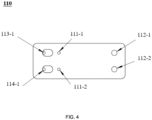
- FIG. 4 is a bottom view illustrating a housing portion according to some embodiments of the present disclosure.
- the sample chamber 111 may be further described below.
- the sample chamber 111 may include a sample inlet 111-3, a first sample outlet 111-1, and a second sample outlet 111-2.
- the sample may be placed into the sample chamber 111 from the sample inlet 111-3 and discharged from the sample chamber 111 through the first sample outlet 111-1 and the second sample outlet 111-2.
- the sample chamber 111 may communicate with the first reaction chamber 121 through the first sample outlet 111-1, and the sample chamber 111 may communicate with the second reaction chamber 122 through the second sample outlet 111-2.
- a nucleic acid detection template obtained by lysis and release in the sample chamber 111 may enter the first reaction chamber 121 through the first sample outlet 111-1 and enter the second reaction chamber 122 through the second sample outlet 111-2 for further amplification reactions.
- the first reaction chamber 121 may communicate with the first sample outlet 111-1 by a first way valve structure 141.
- the first way valve structure 141 may allow the fluid containing the sample to enter the first reaction chamber 121 from the sample chamber 111. That is, the fluid containing the sample in the sample chamber 111 may flow into the first reaction chamber 121 through the first sample outlet 111-1, and the fluid containing the sample cannot flow back into the sample chamber 111 after entering the first reaction chamber 121.
- the second reaction chamber 122 may communicate with the second sample outlet 111-2 through a second way valve structure 142.
- the second way valve structure 142 may allow the fluid containing the sample to enter the second reaction chamber 122 from the sample chamber 111.
- the fluid containing the sample in the sample chamber 111 may flow into the second reaction chamber 122 through the second sample outlet 111-2, and the fluid containing the sample cannot flow back into the sample chamber 111 after entering the second reaction chamber 122.
- the first way valve structure 141 and the second way valve structure 142 may be micro electronically controlled valves.
- the first way valve structure 141 and the second way valve structure 142 may be implemented by the elastic membrane 160, referring to the relevant descriptions below for detail.
- the sample inlet 111-3 may also be disposed with a sample chamber plug (not shown in the figure) for sealing the sample chamber 111.
- the sample chamber plug may block the sample inlet 111-3 to seal the sample chamber 111.
- the sample chamber plug may seal the sample chamber 111 to prevent impurities (e.g., dust) in the external environment from damaging an environment in the sample chamber 111.
- the sample chamber plug may seal the sample chamber 111 after the sample is placed in the sample chamber 111, which may prevent overflow of the fluid within the sample chamber 111 and protect the environment within the sample chamber 111.
- first observation chamber 113 and the second observation chamber 114 are further described below.
- Each of the first observation chamber 113 and the second observation chamber 114 may have an inlet.
- the inlet of the first observation chamber 113 may be a first inlet 113-1
- the inlet of the second observation chamber 114 may be a second inlet 114-1.
- the first observation chamber 113 may communicate with the first reaction chamber 121 through the first inlet 113-1
- the second observation chamber 114 may communicate with the second reaction chamber 122 through the second inlet 114-1.
- the first inlet 113-1 may be disposed at the bottom portion of the first observation chamber 113, and the fluid (e.g., the first amplification reaction product) in the first reaction chamber 121 may enter the first observation chamber 113 through the first inlet 113-1.
- the second inlet 114-1 may be disposed at the bottom portion of the second observation chamber 114, and the fluid (e.g., the second amplification reaction product) in the second reaction chamber 121 may enter the second observation chamber 114 through the second inlet 114-1. For instance, when the piston assembly 130 at least partially moves in the piston chamber 112 along the second direction (e.g.
- the first amplification reaction product in the first reaction chamber 121 may enter the first observation chamber 113 through the first inlet 113-1 under a positive pressure
- the second amplification reaction product in the second reaction chamber 121 may enter the second observation chamber 113 through the second inlet 114-1 under the positive pressure
- the first reaction chamber 121 may include a first sub-chamber 1211 and a second sub-chamber 1212 connected sequentially in a length direction (i.e., an x-direction in FIG. 5 ).
- the first sub-chamber 1211 may communicate with the second sub-chamber 1212.
- a width of the first sub-chamber 1211 may be less than a minimum width of the second sub-chamber 1212.
- the width of the first sub-chamber 1211 may refer to a dimension of the first sub-chamber 1211 in a width direction (i.e., a y-direction in FIG. 5 ).
- the width of the second sub-chamber 1212 may refer to a dimension of the second sub-chamber 1212 in the width direction (i.e., the y-direction in FIG. 5 ). In some embodiments, the width of the second sub-chamber 1212 may vary in the length direction, but the minimum width of the second sub-chamber 1212 may be still greater than the width of the first sub-chamber 1211.
- a depth of the first sub-chamber 1211 may be less than a depth of the second sub-chamber 1212.
- the depth of the first sub-chamber 1211 may refer to a dimension of the first sub-chamber 1211 in a depth direction (i.e., the z-direction in FIG. 3 ).
- the depth of the second sub-chamber 1212 may be a dimension of the second sub-chamber 1212 in the depth direction (i.e., the z-direction in FIG. 3 ).
- the first inlet 113-1 may arrange opposite to the first sub-chamber 1211. That is, the first inlet 113-1 may be opposite to a top opening of the first sub-chamber 1211.
- the first sub-chamber 1211 may have a relatively small width and a relatively small depth. Under a driving action of the piston assembly 130, the fluid (e.g., the first amplification reaction product) in the first sub-chamber 1211 may pass through the first inlet 113-1 to enter the first observation chamber 113 relatively easily.
- the width of the first sub-chamber 1211 may be substantially the same as a diameter of the first inlet 113-1. In some embodiments, the width of the first sub-chamber 1211 may be within a range from 1.0 mm to 1.5 mm, and the width of the second sub-chamber 1212 may be within a range from 1.5 mm to 2.0 mm. In some embodiments, the depth of the first sub-chamber 1211 may be within a range from 0.5mm to 1.0mm, and the depth of the second sub-chamber 1212 may be within a range from 1.5 mm to 2.0 mm.
- the second reaction chamber 122 may include a third sub-chamber 1221 and a fourth sub-chamber 1222 connected sequentially in the length direction (i.e., the x-direction in FIG. 5 ).
- the third sub-chamber 1221 may communicate with the fourth sub-chamber 1222.
- a width of the third sub-chamber 1221 may be less than a minimum width of the fourth sub-chamber 1222.
- the width of the third sub-chamber 1221 may refer to a dimension of the third sub-chamber 1221 in the width direction (i.e., the y-direction in FIG. 5 ).
- the width of the fourth sub-chamber 1222 may refer to a dimension of the fourth sub-chamber 1222 in the width direction (i.e., the y-direction in FIG. 5 ). In some embodiments, the width of the fourth sub-chamber 1222 may vary in the length direction, but the minimum width of the fourth sub-chamber 1222 may be still greater than the width of the third sub-chamber 1221. A depth of the third sub-chamber 1221 may be less than a depth of the fourth sub-chamber 1222. The depth of the third sub-chamber 1221 may refer to a dimension of the third sub-chamber 1221 in the depth direction (i.e., the z-direction in FIG. 3 , similar to the depth of the first sub-chamber 1211).
- the depth of the fourth sub-chamber 1222 may refer to a dimension of the fourth sub-chamber 1222 in the depth direction (i.e., the z-direction in FIG. 3 , similar to the depth of the second sub-chamber 1212).
- the second inlet 114-1 may arrange opposite to the third sub-chamber 1221. That is, the second inlet 114-1 may be located opposite to a top opening of the third sub-chamber 1221.
- the third sub-chamber 1221 may have a relatively small width and a relatively small depth. Under the driving action of the piston assembly 130, the fluid (e.g., the second amplification reaction product) in the third sub-chamber 1221 may more easily pass through the second inlet 114-1 to enter the second observation chamber 114.
- the width of the third sub-chamber 1221 may be substantially the same as the diameter of the second inlet 114-1. In some embodiments, the width of the third sub-chamber 1221 may be within a range from 1.0 mm to 1.5 mm. The width of the fourth sub-chamber 1222 may be within a range from 1.5 mm to 2.0 mm. The depth of the third sub-chamber 1221 may be within a range from 0.5 mm to 1.0 mm. The width of the fourth sub-chamber 1222 may be within a range from 1.5 mm to 2.0 mm.
- the second sub-chamber 1212 may arrange opposite to the first sample outlet 111-1 of the sample chamber 111. That is, the first sample outlet 111-1 may be opposite to a top opening of the second sub-chamber 1212.
- the fourth sub-chamber 1222 may arrange opposite to the second sample outlet 111-2 of the sample chamber 111. That is, the second sample outlet 111-2 may be opposite to a top opening of the fourth sub-chamber 1222.
- a partition may be disposed in the piston chamber 112.
- the piston chamber 112 may be divided into a fifth sub-chamber 1121 and a sixth sub-chamber 1122 by the partition.
- the partition within the piston chamber 112 may be disposed in the depth direction (e.g., the z-direction in FIG. 1 or FIG. 3 ) of the piston chamber 112 to divide the piston chamber 112 into the fifth sub-chamber 1121 and the sixth sub-chamber 1122 distributed side-by-side in the width direction (e.g., the y-direction in FIG. 1 ).
- the fifth sub-chamber 1121 (e.g., a bottom portion of the fifth sub-chamber 1121) may include a first opening 112-1.
- the fifth sub-chamber 1121 may communicate with the first reaction chamber 121 of the reaction portion 120 through the first opening 112-1.
- the sixth sub-chamber 1122 (e.g., a bottom portion of the sixth sub-chamber 1122) may include a second opening 112-2.
- the sixth sub-chamber 1122 may communicate with the second reaction chamber 122 of the reaction portion 120 through the second opening 112-2.
- the second sub-chamber 1212 may at least include a first portion 1212-1 and a second portion 1212-2.
- a width of the first portion 1212-1 may be larger than a width of the second portion 1212-2.
- the first opening 112-1 may arrange opposite to the second portion 1212-2.
- the width of the second portion 1212-2 may be substantially the same as a diameter of the first opening 112-1.
- the fourth sub-chamber 1222 may at least include a third portion 1222-1 and a fourth portion 1222-2.
- a width of the third portion 1222-1 may be larger than a width of the fourth portion 1222-2.
- the second opening may arrange opposite to the fourth portion 1222-2.
- the width of the fourth portion 1222-2 may be substantially the same as the diameter of the second opening. It should be understood that, the widths of the first portion 1212-1, the second portion 1212-2, the third portion 1222-1, and the fourth portion 1222-2 may be understood as the dimensions of the above four portions in the width direction (i.e., the y-direction shown in FIG. 5 ).
- the piston assembly 130 may be able to apply the positive or negative pressure to the first reaction chamber 121 and the second reaction chamber 122 more stably, and the first reaction chamber 121 and the second reaction chamber 122 may be able to maintain gas tightness better.
- FIG. 6 is a schematic diagram illustrating an exemplary structure of a piston assembly according to some embodiments of the present disclosure.
- the piston assembly 130 may comprise a first piston 131 and a second piston 132.
- the first piston 131 may be disposed within the fifth sub-chamber 1121 of the piston chamber 112, and the second piston 132 may be disposed within the sixth sub-chamber 1122 of the piston chamber 112.
- the first piston 131 may move within the fifth sub-chamber 1121 of the piston chamber 112.
- the first piston 131 When the first piston 131 moves within the fifth sub-chamber 1121, the first piston 131 may form a positive or negative pressure within the first reaction chamber 121, thereby driving the fluid to circulate between various chambers (e.g., the sample chamber 111 and the first reaction chamber 121, the first reaction chamber 121 and the first observation chamber 113).
- the second piston 132 may move within the sixth sub-chamber 1122 of the piston chamber 112.
- the second piston 132 When the second piston 132 moves within the sixth sub-chamber 1122, the second piston 132 may form a positive or negative pressure within the second reaction chamber 122, and the positive or negative pressure may act on the elastic membrane 160 to drive the fluid to circulate between various chambers (e.g., the sample chamber 111 and the second reaction chamber 122, the second reaction chamber 122 and the second observation chamber 114), referring to the relevant description below for detail.
- various chambers e.g., the sample chamber 111 and the second reaction chamber 122, the second reaction chamber 122 and the second observation chamber 114
- the movement of the first piston 131 in the fifth sub-chamber 1121 and the movement of the second piston 132 in the sixth sub-chamber 1122 may be controlled, respectively.
- the first piston 131 and the second piston 132 may move synchronously. That is, the movement of the first piston 131 in the fifth sub-chamber 1121 and the movement of the second piston 132 in the sixth sub-chamber 1122 may be controlled in unison.
- the piston assembly may further include a first piston rod 134, a second piston rod 135, and a connector 133.
- first piston rod 134 may connect to the first piston 131
- one end of the second piston rod 135 may connect to the second piston 132
- the connector 133 may connect to both the other end of the first piston rod 134 and the other end of the second piston rod 135.
- the first piston 131 and the second piston 132 may be controlled in unison, and the fluid containing the sample in the sample chamber 111 may be fed into the first reaction chamber 121 and the second reaction chamber 122 when the operator only operates one time (e.g., pulling the connector 133 in the first direction).
- the first amplification reaction product within the first reaction chamber 121 may be fed into the first observation chamber 113
- the second amplification reaction product within the second reaction chamber 122 may be fed into the second observation chamber 114.
- the first way valve structure 141 and the second way valve structure 142 may be formed by the elastic membrane 60.
- the elastic membrane 160 may be configured to include a first through hole 161 and a second through hole 162.
- the first through hole 161 may communicate with the first reaction chamber 121.
- the first through hole 161 may be located at a top opening of the first reaction chamber 121.
- the first through hole 161 may be staggered with the first sample outlet 111-1 of the sample chamber 111, so that the elastic membrane 160 and the first through hole 161 thereon may form the first way valve structure 141.
- the first through hole 161 being staggered with the first sample outlet 111-1 of the sample chamber 111 may be understood as that the first through hole 161 does not overlap with the first sample outlet 111-1, thereby making the first sample outlet 111-1 to be blocked by the elastic membrane 160.
- the relevant principles of the first way valve structure 141 may refer to the relevant description below.
- the second through hole 162 may communicate with the second reaction chamber 122.
- the second through hole 162 may be located at a top opening of the second reaction chamber 122.
- the second through hole 162 may be staggered with the second sample outlet 111-2 of the sample chamber 111, so that the elastic membrane 160 and the second through hole 162 thereon may form the second way valve structure 142.
- the second through hole 162 being staggered with the second sample outlet 111-2 of the sample chamber 111 may be understood as that the second through hole 162 does not overlap with the second sample outlet 111-2, thereby making the second sample outlet 111-2 to be blocked by the elastic membrane 160.
- the principles of the second way valve structure 142 may be similar to those of the first way valve structure 141.
- the elastic membrane 160 when the elastic membrane 160 is in an initial state, the elastic membrane 160 may block the first sample outlet 111-2 and the second sample outlet 111-2.
- the piston assembly 130 at least partially moves in the piston chamber 112 along the first direction (e.g. the direction away from the reaction portion 120)
- a negative pressure may be formed in both the first reaction chamber 121 and the second reaction chamber 122, making the elastic membrane 160 to deform under the negative pressure (e.g. deform toward the first reaction chamber 121 and the second reaction chamber 122), thereby making the first sample outlet 111-1 and the second sample outlet 111-2 to change from a state in which the first sample outlet and the second sample outlet are blocked by the elastic membrane 160 to a state in which the fluid containing the sample is allowed to flow out.
- the first way valve structure 141 may allow the fluid containing the sample to flow from the sample chamber 111 to the first reaction chamber 121
- the second way valve structure 142 may allow the fluid containing the sample to flow from the sample chamber 111 to the second reaction chamber 122.
- the second sub-chamber 1212 may communicate with the first sample outlet 111-1 of the sample chamber 111 via the first way valve structure 141.
- the first sample outlet 111-1 and the first through hole 161 may both be located at the top opening of the second sub-chamber 1212.
- the fourth sub-chamber 1222 may communicate with the second sample outlet 111-2 of the sample chamber 111 by the second way valve structure 142.
- the second sample outlet 111-2 and the second through hole 162 may both be located at the top opening of the fourth sub-chamber 1222.
- the elastic membrane 160 may be configured to include a third through hole 163 and a fourth through hole 164.
- the first inlet 113-1 may communicate with the first reaction chamber 121 through the third through hole 163, and the second inlet 114-1 may communicate with the second reaction chamber 122 through the fourth through hole 164.
- the third through hole 163 may be located at the top opening of the first reaction chamber 121 and the fourth through hole 164 may be located at the top opening of the second reaction chamber 122.
- the third through hole 163 may arrange opposite to the first inlet 113-1, so that the elastic membrane 160 and the third through hole 163 thereon may form a third way valve structure 143.
- the fourth through hole 164 may arrange opposite to the second inlet 114-1, so that the elastic membrane 160 and the fourth through hole 164 thereon may form a fourth way valve structure 144.
- a positive pressure may be formed both in the first reaction chamber 121 and the second reaction chamber 122.
- the fluid in the first reaction chamber 121 may enter the first observation chamber 113 under the positive pressure through the third way valve structure 143 and the first inlet 113-1, and the fluid in the second reaction chamber 122 may enter the second observation chamber 114 under the positive pressure through the fourth way valve structure 144 and the second inlet 114-1.
- the third through hole 163 may be disposed correspondence to the first sub-chamber 1211 of the first reaction chamber 121 to facilitate that the fluid (e.g., the first amplification reaction product) in the first reaction chamber 121 flows into the first observation chamber 113 through the first sub-chamber 1211 and the third through hole 163.
- the fourth through hole 164 may be disposed correspondence to the third sub-chamber 1221 of the second reaction chamber 122 to facilitate that the fluid (e.g., the second amplification reaction product) in the second reaction chamber 122 to flow into the second observation chamber 114 through the third sub-chamber 1213 and the fourth through hole 164.
- the elastic membrane 160 may also be configured to include a fifth through hole 165 and a sixth through hole 166.
- the piston chamber 112 e.g., the first opening 112-1 of the piston chamber 112 may communicate with the first reaction chamber 121 through the fifth through hole 165, and the piston chamber 112 (e.g., the second opening 112-2 of the piston chamber 112) may communicate with the second reaction chamber 122 through the sixth through hole 166.
- the negative or positive pressure may act on the first reaction chamber 121 through the first opening 112-1 and the fifth through hole 165, and act on the second reaction chamber 122 through the second opening 112-2 and the sixth through hole 166, thereby making the fluid to flow in the different chambers.
- the fifth through hole 165 of the elastic membrane 160 may be configured to include a hydrophobic breathable membrane 150.
- the sixth through hole 166 of the elastic membrane 160 may be configured to include the hydrophobic breathable membrane 150.
- the hydrophobic permeable membrane 150 may allow air to pass through and prevent liquid from passing through.
- the nucleic acid detection device 100 may also include a sealing membrane 170.
- the sealing membrane 170 may seal the nucleic acid detection device 100, so that the nucleic acid detection device 100 forms a fully enclosed structure.
- the use of the sealing membrane 170 in combination with components such as the sample chamber plug may also prevent cross-contamination between the chambers of the nucleic acid detection device 100 and cross-contamination between the chambers and the external environment.
- the nucleic acid detection device may also include a heating assembly (not shown in the figures) disposed at the bottom portion of the reaction portion 120.
- the heating assembly may heat the first reaction chamber 121 and the second reaction chamber 122, thereby providing a suitable reaction temperature for the amplification reaction performed in the first reaction chamber 121 and the second reaction chamber 122 to achieve the amplification reaction of the nucleic acid detection template.
- the heating assembly may include a resistance heating assembly, an infrared heating assembly, etc.
- the nucleic acid detection device 100 may also be disposed with no heating assembly, but the reaction portion 120 may be heated by an external heating device (e.g., a thermostatic metal bath device) to provide the suitable reaction temperature.
- a dimension of the nucleic acid detection device 100 in the length direction may be within a range from 35 to 48 mm.
- a dimension of the nucleic acid detection device 100 in the width direction i.e., the y-direction in FIG. 1
- a dimension of the nucleic acid detection device 100 in the depth direction i.e., the z-direction in FIG. 1
- a size of the nucleic acid detection device may be small, which is convenient to carry and transport.
- the present disclosure further provides a nucleic acid detection method.
- the nucleic acid detection method may use the nucleic acid detection device 100 described in any of the above technical solutions to achieve the nucleic acid detection on viruses or bacteria.
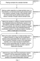
- FIG. 7 is a flowchart illustrating a nucleic acid detection process according to some embodiments of the present disclosure.
- the nucleic acid detection process may include one or more of the following operations.
- a sample may be placed into the sample chamber 111.
- the sample may be a nasal swab sample, a pharyngeal swab sample, etc.
- a sample release agent may be pre-stored within the sample chamber 111.
- a nasal swab sample or pharyngeal swab sample may be collected and placed in the sample chamber 111 and the nasal swab sample or the pharyngeal swab sample may be immersed with the sample release agent for repeated swabbing (e.g., about 15 times), and then the swab may be removed.
- the sample chamber may be covered with a sample chamber plug. The sample may be uniformly mixed with the sample release agent.
- the sample release agent after the sample is mixed with the sample release agent, standing for 1-20 minutes may be performed to allow the sample to undergo sufficient lysis and release to obtain a nucleic acid detection template. In some embodiments, after the sample is mixed with the sample release agent, standing for 5-10 minutes may be performed.
- the piston assembly 130 may be made to at least partially move in a first direction, so that fluid containing the sample enters the first reaction chamber 121 through the first sample outlet 111-1, and fluid containing the sample enters the second reaction chamber 122 through the second sample outlet 111-2.
- the first direction may refer to a direction away from the reaction portion 120 along the piston chamber 112.
- the piston assembly 130 e.g., the first piston 131 and the second piston 132 may be pulled in the direction away from the reaction portion 120, making the fluid containing the sample obtained in operation 2 (i.e., the fluid containing the nucleic acid detection template) to enter the first reaction chamber 121 and the second reaction chamber 122, respectively.
- the sample may be made to undergo a reverse transcription loop-mediated isothermal amplification reaction in the first reaction chamber 121 to detect an internal standard gene of the sample, and the sample may be made to undergo a reverse transcription loop-mediated isothermal amplification reaction in the second reaction chamber 122 to detect a target gene of the sample.
- the reverse transcription refers to a process of synthesizing DNA using RNA as a template.
- the loop-mediated isothermal amplification reaction is a novel isothermal nucleic acid amplification manner.
- the feature of the loop-mediated isothermal amplification reaction may include that four specific primers are designed for six regions of a target gene, constant temperature amplification is performed under the action of strand displacement DNA polymerase (Bst DNA polymerase), and 10 9 to 10 10 times of nucleic acid amplification is achieved in a short time (e.g., about 15-60 minutes).
- the first reaction chamber 121 may be pre-loaded with a reverse transcription loop-mediated isothermal amplification lyophilization reaction reagent for housekeeping genes, such as, the RnaseP gene loop-mediated isothermal amplification lyophilization reaction reagent formula described above.
- the nucleic acid detection device 100 may be placed on a heating device (e.g., a thermostatic metal bath device) for heating to initiate the nucleic acid isothermal amplification reaction, making the reverse transcription loop-mediated isothermal amplification reaction to occur within the first reaction chamber 121 to obtain a first amplification reaction product.
- a heating device e.g., a thermostatic metal bath device
- the nucleic acid detection device 100 may be heated at a temperature range from 50°C to 75°C. In some embodiments, the nucleic acid detection device 100 may be heated at a temperature range from 60°C to 65°C. In some embodiments, the nucleic acid detection device 100 may be heated for 5 to 50 minutes. That is, the amplification reaction time may be within a range of 5 to 50 minutes. In some embodiments, the nucleic acid detection device 100 may be heated for 30 to 40 minutes.
- the second reaction chamber 122 may be pre-loaded with a reverse transcription loop-mediated isothermal amplification lyophilization reaction reagent for virus or bacterium to be detected, such as, the reverse transcription loop-mediated isothermal amplification lyophilization reaction reagent formula for the novel coronavirus described above.
- a reverse transcription loop-mediated isothermal amplification lyophilization reaction reagent for virus or bacterium to be detected such as, the reverse transcription loop-mediated isothermal amplification lyophilization reaction reagent formula for the novel coronavirus described above.
- the reverse transcription loop-mediated isothermal amplification reaction may occur within the second reaction chamber 122 to obtain a second amplification reaction product.
- the piston assembly 130 may be made to at least partially move in a second direction to make the first amplification reaction product generated after the reaction occurs in the first reaction chamber 121 to enter a first observation chamber 113, and to make the second amplification reaction product generated after the reaction occurs in the second reaction chamber 122 to enter a second observation chamber 114.
- the second direction may refer to a direction close to the reaction portion 120 along the piston chamber 112.
- the piston assembly 130 e.g., the first piston 131 and the second piston 132
- the piston assembly 130 may be pushed toward the reaction portion 120, so that the first amplification reaction product obtained in operation 3 enters the first observation chamber 113, and the second amplification reaction product obtained in operation 3 enters the second observation chamber 114.
- a color of the fluid in the first observation chamber 113 may be determined, and a color of the fluid in the second observation chamber 114 may be determined.
- the color of the first amplification reaction product in the first observation chamber 113 may be observed with naked eyes through the first observation port 113-2 to determine a detection result of the internal standard gene
- the color of the second amplification reaction product in the second observation chamber 114 may be observed with the naked eyes through the second observation port 114-2 to determine a detection result of the target gene.
- a nucleic acid detection result may be determined based on the detection of the internal standard gene and the detection of the target gene. More descriptions regarding the determination of the detection result may be referred to the relevant description above.
- the nucleic acid detection device 100 and the nucleic acid detection method provided by some embodiments of the present disclosure may be used to detect viruses, bacteria, etc., such as, viruses or bacteria from human bodies or animal bodies. In some embodiments, the nucleic acid detection device 100 and the nucleic acid detection method provided by some embodiments of the present disclosure may be used to detect novel coronaviruses.
- the five negative samples were all nasal swab samples or pharyngeal swab samples collected from healthy individuals using nasopharyngeal swabs or oropharyngeal swabs.
- the five positive samples were all pseudovirus nucleic acid standard substances of novel coronavirus (SARS-CoV-2).
- the process of the nucleic acid detection was as follows. Firstly, the sample chamber plug of the sample chamber 111 was opened, 200 uL of the pseudovirus nucleic acid standard substances of novel coronavirus (SARS-CoV-2) were taken and placed into the sample chamber 111, the sample was uniformly mixed with the sample release agent by repeated blowing and beating with a pipette, and the sample chamber was covered with the sample chamber plug to stand for 5-10 minutes at the room temperature to obtain the sample release agent containing the nucleic acid template.
- SARS-CoV-2 novel coronavirus
- the piston assembly 130 was pulled in the first direction so that the sample release agent containing the nucleic acid template entered the first reaction chamber 121 and the second reaction chamber 122, respectively, and the entire nucleic acid detection device 100 was placed on the thermostatic metal bath device for heating (the heating temperature of 60°C-65°C) to initiate the nucleic acid isothermal amplification reaction, and the amplification reaction lasting for 30-40 minutes. Thereafter, when the amplification reaction is finished, the nucleic acid detection device was removed and the piston assembly 130 was pushed in the second direction. The first amplification reaction product in the first reaction chamber 121 entered the first observation chamber 113, and the second amplification reaction product in the second reaction chamber 122 entered the second observation chamber 114. The colors of the first amplification reaction product and the second amplification reaction product were observed with the naked eyes to determine the nucleic acid detection result.
- the numbers expressing quantities or properties used to describe and claim certain embodiments of the application are to be understood as being modified in some instances by the term "about,” “approximate,” or “substantially.” For example, “about,” “approximate,” or “substantially” may indicate ⁇ 20% variation of the value it describes, unless otherwise stated. Accordingly, in some embodiments, the numerical parameters set forth in the written description and attached claims are approximations that may vary depending upon the desired properties sought to be obtained by a particular embodiment. In some embodiments, the numerical parameters should be construed in light of the number of reported significant digits and by applying ordinary rounding techniques. Notwithstanding that the numerical ranges and parameters setting forth the broad scope of some embodiments of the application are approximations, the numerical values set forth in the specific examples are reported as precisely as practicable.
Landscapes
- Chemical & Material Sciences (AREA)
- Health & Medical Sciences (AREA)
- Chemical Kinetics & Catalysis (AREA)
- Life Sciences & Earth Sciences (AREA)
- General Health & Medical Sciences (AREA)
- Clinical Laboratory Science (AREA)
- Analytical Chemistry (AREA)
- Organic Chemistry (AREA)
- Molecular Biology (AREA)
- Zoology (AREA)
- Hematology (AREA)
- Biochemistry (AREA)
- Engineering & Computer Science (AREA)
- Proteomics, Peptides & Aminoacids (AREA)
- Wood Science & Technology (AREA)
- Bioinformatics & Cheminformatics (AREA)
- Microbiology (AREA)
- Biotechnology (AREA)
- General Engineering & Computer Science (AREA)
- Biophysics (AREA)
- Genetics & Genomics (AREA)
- Physics & Mathematics (AREA)
- Immunology (AREA)
- Apparatus Associated With Microorganisms And Enzymes (AREA)
- Measuring Or Testing Involving Enzymes Or Micro-Organisms (AREA)
Applications Claiming Priority (2)
| Application Number | Priority Date | Filing Date | Title |
|---|---|---|---|
| CN202210400960.1A CN114480102A (zh) | 2022-04-18 | 2022-04-18 | 一种核酸检测装置及核酸检测方法 |
| PCT/CN2023/079823 WO2023202246A1 (zh) | 2022-04-18 | 2023-03-06 | 一种核酸检测装置及核酸检测方法 |
Publications (2)
| Publication Number | Publication Date |
|---|---|
| EP4286509A1 true EP4286509A1 (de) | 2023-12-06 |
| EP4286509A4 EP4286509A4 (de) | 2024-09-18 |
Family
ID=81489444
Family Applications (1)
| Application Number | Title | Priority Date | Filing Date |
|---|---|---|---|
| EP23754691.6A Pending EP4286509A4 (de) | 2022-04-18 | 2023-03-06 | Nukleinsäurenachweisvorrichtung und nukleinsäurenachweisverfahren |
Country Status (4)
| Country | Link |
|---|---|
| EP (1) | EP4286509A4 (de) |
| CN (2) | CN114480102A (de) |
| AU (1) | AU2023219983B2 (de) |
| WO (1) | WO2023202246A1 (de) |
Families Citing this family (2)
| Publication number | Priority date | Publication date | Assignee | Title |
|---|---|---|---|---|
| CN114480102A (zh) * | 2022-04-18 | 2022-05-13 | 杭州安旭生物科技股份有限公司 | 一种核酸检测装置及核酸检测方法 |
| CN115029229A (zh) * | 2022-06-21 | 2022-09-09 | 成都万众壹芯生物科技有限公司 | 一种基于负压系统的核酸检测试剂盒 |
Family Cites Families (12)
| Publication number | Priority date | Publication date | Assignee | Title |
|---|---|---|---|---|
| US9795968B2 (en) * | 2014-04-21 | 2017-10-24 | Lawrence Livermore National Security, LLCq | Multi-chamber nucleic acid amplification and detection device |
| EP4062962B1 (de) * | 2015-12-03 | 2023-10-04 | C A Casyso GmbH | Bluttestsystem und -verfahren |
| JP7289792B2 (ja) * | 2017-04-21 | 2023-06-12 | メサ バイオテック,インク. | 流体検査用カセット |
| CN210065721U (zh) * | 2018-11-26 | 2020-02-14 | 杭州比格飞序生物科技有限公司 | 一种核酸提取装置 |
| CN111647498B (zh) * | 2020-05-25 | 2022-03-22 | 杭州梓晶生物有限公司 | 一种一体化自助式核酸检测装置及其使用方法 |
| WO2021254505A1 (zh) * | 2020-06-19 | 2021-12-23 | 安徽为臻生物工程技术有限公司 | 一种用于核酸扩增物快速检测的防污染检测装置、方法及应用 |
| CN213951203U (zh) * | 2020-07-14 | 2021-08-13 | 四川大学 | 快速核酸检测系统及装置 |
| CN112029900A (zh) * | 2020-07-14 | 2020-12-04 | 四川大学 | 新型冠状病毒的快速核酸检测方法及检测系统 |
| CN215947247U (zh) * | 2021-01-15 | 2022-03-04 | 江苏汇先医药技术有限公司 | 一种环介导等温扩增芯片 |
| CN113186345A (zh) * | 2021-04-30 | 2021-07-30 | 青岛浩铂生物科技有限公司 | 一种快速检测病毒核酸的方法及其检测装置 |
| CN215906211U (zh) * | 2021-07-30 | 2022-02-25 | 北京清风堂医药科技有限公司 | 口袋式扩增设备 |
| CN114480102A (zh) * | 2022-04-18 | 2022-05-13 | 杭州安旭生物科技股份有限公司 | 一种核酸检测装置及核酸检测方法 |
-
2022
- 2022-04-18 CN CN202210400960.1A patent/CN114480102A/zh active Pending
- 2022-04-18 CN CN202211176859.9A patent/CN115353966A/zh active Pending
-
2023
- 2023-03-06 WO PCT/CN2023/079823 patent/WO2023202246A1/zh not_active Ceased
- 2023-03-06 AU AU2023219983A patent/AU2023219983B2/en active Active
- 2023-03-06 EP EP23754691.6A patent/EP4286509A4/de active Pending
Also Published As
| Publication number | Publication date |
|---|---|
| EP4286509A4 (de) | 2024-09-18 |
| AU2023219983B2 (en) | 2025-02-13 |
| CN115353966A (zh) | 2022-11-18 |
| AU2023219983A1 (en) | 2023-11-02 |
| CN114480102A (zh) | 2022-05-13 |
| WO2023202246A1 (zh) | 2023-10-26 |
Similar Documents
| Publication | Publication Date | Title |
|---|---|---|
| US20230405589A1 (en) | Sample preparation, processing and analysis systems | |
| US9816135B2 (en) | Fluidic cartridge for nucleic acid amplification and detection | |
| CN104136596B (zh) | 样品制备、处理和分析系统 | |
| EP2048245B1 (de) | Vollständig umschlossene vorrichtung zum schnellnachweis eines zielnukleinsäureamplifikationsprodukts | |
| US20090061450A1 (en) | System and method for diagnosis of infectious diseases | |
| US10661271B2 (en) | Device, system and method for processing a sample | |
| EP4286509A1 (de) | Nukleinsäurenachweisvorrichtung und nukleinsäurenachweisverfahren | |
| JP5049274B2 (ja) | 自動化医療診断のためのカートリッジ | |
| US20030032172A1 (en) | Automated nucleic acid assay system | |
| US9908114B2 (en) | Cartridge, cartridge reader and method for preventing reuse of the cartridge | |
| WO2007106552A2 (en) | System and method for diagnosis of infectious diseases | |
| CN101203312A (zh) | 用于自动医疗诊断的盒体、系统和方法 | |
| US10589276B2 (en) | Multi-functional microfluidics device for biological sample screening | |
| DE102014105437A1 (de) | Mikrofluidik-Modul und Kassette für die immunologische und molekulare Diagnostik in einem Analyseautomaten | |
| US20250128262A1 (en) | Molecular diagnostic devices and methods for retaining and mixing reagents | |
| CN109486665A (zh) | 一种核酸扩增杂交生物芯片反应管 | |
| US11565233B2 (en) | Integrated tubular reaction device | |
| HK40074380A (en) | Nucleic acid testing device and nucleic acid testing method | |
| JP2023546179A (ja) | 分子poc診断システム内で統合された熱調節及びpcr | |
| Tupik et al. | Microchip device with dry-stored reagents for Loop mediated isothermal amplification | |
| Suvorova et al. | Rapid determination of sexually transmitted infections by real-time polymerase chain reaction using microchip analyzer | |
| Foo et al. | Development of a microfluidic chip for early and rapid detection of multiple dengue serotypes | |
| KR20230021634A (ko) | 체외 진단 시스템의 현장 진료 미세 유체 |
Legal Events
| Date | Code | Title | Description |
|---|---|---|---|
| STAA | Information on the status of an ep patent application or granted ep patent |
Free format text: STATUS: UNKNOWN |
|
| STAA | Information on the status of an ep patent application or granted ep patent |
Free format text: STATUS: THE INTERNATIONAL PUBLICATION HAS BEEN MADE |
|
| PUAI | Public reference made under article 153(3) epc to a published international application that has entered the european phase |
Free format text: ORIGINAL CODE: 0009012 |
|
| STAA | Information on the status of an ep patent application or granted ep patent |
Free format text: STATUS: REQUEST FOR EXAMINATION WAS MADE |
|
| 17P | Request for examination filed |
Effective date: 20230823 |
|
| AK | Designated contracting states |
Kind code of ref document: A1 Designated state(s): AL AT BE BG CH CY CZ DE DK EE ES FI FR GB GR HR HU IE IS IT LI LT LU LV MC ME MK MT NL NO PL PT RO RS SE SI SK SM TR |
|
| A4 | Supplementary search report drawn up and despatched |
Effective date: 20240820 |
|
| RIC1 | Information provided on ipc code assigned before grant |
Ipc: B01L 3/00 20060101ALI20240813BHEP Ipc: B01L 7/00 20060101ALI20240813BHEP Ipc: C12Q 1/6844 20180101ALI20240813BHEP Ipc: C12M 1/00 20060101ALI20240813BHEP Ipc: C12M 1/34 20060101AFI20240813BHEP |
|
| DAV | Request for validation of the european patent (deleted) | ||
| DAX | Request for extension of the european patent (deleted) |