EP4286311A1 - Hose reel assembly - Google Patents
Hose reel assembly Download PDFInfo
- Publication number
- EP4286311A1 EP4286311A1 EP22176338.6A EP22176338A EP4286311A1 EP 4286311 A1 EP4286311 A1 EP 4286311A1 EP 22176338 A EP22176338 A EP 22176338A EP 4286311 A1 EP4286311 A1 EP 4286311A1
- Authority
- EP
- European Patent Office
- Prior art keywords
- hose reel
- hose
- mobile
- drive motor
- housing
- Prior art date
- Legal status (The legal status is an assumption and is not a legal conclusion. Google has not performed a legal analysis and makes no representation as to the accuracy of the status listed.)
- Granted
Links
Images


Classifications
-
- B—PERFORMING OPERATIONS; TRANSPORTING
- B65—CONVEYING; PACKING; STORING; HANDLING THIN OR FILAMENTARY MATERIAL
- B65H—HANDLING THIN OR FILAMENTARY MATERIAL, e.g. SHEETS, WEBS, CABLES
- B65H75/00—Storing webs, tapes, or filamentary material, e.g. on reels
- B65H75/02—Cores, formers, supports, or holders for coiled, wound, or folded material, e.g. reels, spindles, bobbins, cop tubes, cans, mandrels or chucks
- B65H75/34—Cores, formers, supports, or holders for coiled, wound, or folded material, e.g. reels, spindles, bobbins, cop tubes, cans, mandrels or chucks specially adapted or mounted for storing and repeatedly paying-out and re-storing lengths of material provided for particular purposes, e.g. anchored hoses, power cables
- B65H75/38—Cores, formers, supports, or holders for coiled, wound, or folded material, e.g. reels, spindles, bobbins, cop tubes, cans, mandrels or chucks specially adapted or mounted for storing and repeatedly paying-out and re-storing lengths of material provided for particular purposes, e.g. anchored hoses, power cables involving the use of a core or former internal to, and supporting, a stored package of material
- B65H75/40—Cores, formers, supports, or holders for coiled, wound, or folded material, e.g. reels, spindles, bobbins, cop tubes, cans, mandrels or chucks specially adapted or mounted for storing and repeatedly paying-out and re-storing lengths of material provided for particular purposes, e.g. anchored hoses, power cables involving the use of a core or former internal to, and supporting, a stored package of material mobile or transportable
- B65H75/406—Cores, formers, supports, or holders for coiled, wound, or folded material, e.g. reels, spindles, bobbins, cop tubes, cans, mandrels or chucks specially adapted or mounted for storing and repeatedly paying-out and re-storing lengths of material provided for particular purposes, e.g. anchored hoses, power cables involving the use of a core or former internal to, and supporting, a stored package of material mobile or transportable hand-held during use
-
- B—PERFORMING OPERATIONS; TRANSPORTING
- B65—CONVEYING; PACKING; STORING; HANDLING THIN OR FILAMENTARY MATERIAL
- B65H—HANDLING THIN OR FILAMENTARY MATERIAL, e.g. SHEETS, WEBS, CABLES
- B65H75/00—Storing webs, tapes, or filamentary material, e.g. on reels
- B65H75/02—Cores, formers, supports, or holders for coiled, wound, or folded material, e.g. reels, spindles, bobbins, cop tubes, cans, mandrels or chucks
- B65H75/34—Cores, formers, supports, or holders for coiled, wound, or folded material, e.g. reels, spindles, bobbins, cop tubes, cans, mandrels or chucks specially adapted or mounted for storing and repeatedly paying-out and re-storing lengths of material provided for particular purposes, e.g. anchored hoses, power cables
- B65H75/38—Cores, formers, supports, or holders for coiled, wound, or folded material, e.g. reels, spindles, bobbins, cop tubes, cans, mandrels or chucks specially adapted or mounted for storing and repeatedly paying-out and re-storing lengths of material provided for particular purposes, e.g. anchored hoses, power cables involving the use of a core or former internal to, and supporting, a stored package of material
- B65H75/44—Constructional details
- B65H75/4481—Arrangements or adaptations for driving the reel or the material
- B65H75/4492—Manual drives
-
- B—PERFORMING OPERATIONS; TRANSPORTING
- B65—CONVEYING; PACKING; STORING; HANDLING THIN OR FILAMENTARY MATERIAL
- B65H—HANDLING THIN OR FILAMENTARY MATERIAL, e.g. SHEETS, WEBS, CABLES
- B65H59/00—Adjusting or controlling tension in filamentary material, e.g. for preventing snarling; Applications of tension indicators
- B65H59/38—Adjusting or controlling tension in filamentary material, e.g. for preventing snarling; Applications of tension indicators by regulating speed of driving mechanism of unwinding, paying-out, forwarding, winding, or depositing devices, e.g. automatically in response to variations in tension
- B65H59/382—Adjusting or controlling tension in filamentary material, e.g. for preventing snarling; Applications of tension indicators by regulating speed of driving mechanism of unwinding, paying-out, forwarding, winding, or depositing devices, e.g. automatically in response to variations in tension using mechanical means
-
- B—PERFORMING OPERATIONS; TRANSPORTING
- B65—CONVEYING; PACKING; STORING; HANDLING THIN OR FILAMENTARY MATERIAL
- B65H—HANDLING THIN OR FILAMENTARY MATERIAL, e.g. SHEETS, WEBS, CABLES
- B65H59/00—Adjusting or controlling tension in filamentary material, e.g. for preventing snarling; Applications of tension indicators
- B65H59/38—Adjusting or controlling tension in filamentary material, e.g. for preventing snarling; Applications of tension indicators by regulating speed of driving mechanism of unwinding, paying-out, forwarding, winding, or depositing devices, e.g. automatically in response to variations in tension
- B65H59/384—Adjusting or controlling tension in filamentary material, e.g. for preventing snarling; Applications of tension indicators by regulating speed of driving mechanism of unwinding, paying-out, forwarding, winding, or depositing devices, e.g. automatically in response to variations in tension using electronic means
- B65H59/387—Regulating unwinding speed
-
- B—PERFORMING OPERATIONS; TRANSPORTING
- B65—CONVEYING; PACKING; STORING; HANDLING THIN OR FILAMENTARY MATERIAL
- B65H—HANDLING THIN OR FILAMENTARY MATERIAL, e.g. SHEETS, WEBS, CABLES
- B65H75/00—Storing webs, tapes, or filamentary material, e.g. on reels
- B65H75/02—Cores, formers, supports, or holders for coiled, wound, or folded material, e.g. reels, spindles, bobbins, cop tubes, cans, mandrels or chucks
- B65H75/34—Cores, formers, supports, or holders for coiled, wound, or folded material, e.g. reels, spindles, bobbins, cop tubes, cans, mandrels or chucks specially adapted or mounted for storing and repeatedly paying-out and re-storing lengths of material provided for particular purposes, e.g. anchored hoses, power cables
- B65H75/38—Cores, formers, supports, or holders for coiled, wound, or folded material, e.g. reels, spindles, bobbins, cop tubes, cans, mandrels or chucks specially adapted or mounted for storing and repeatedly paying-out and re-storing lengths of material provided for particular purposes, e.g. anchored hoses, power cables involving the use of a core or former internal to, and supporting, a stored package of material
-
- B—PERFORMING OPERATIONS; TRANSPORTING
- B65—CONVEYING; PACKING; STORING; HANDLING THIN OR FILAMENTARY MATERIAL
- B65H—HANDLING THIN OR FILAMENTARY MATERIAL, e.g. SHEETS, WEBS, CABLES
- B65H75/00—Storing webs, tapes, or filamentary material, e.g. on reels
- B65H75/02—Cores, formers, supports, or holders for coiled, wound, or folded material, e.g. reels, spindles, bobbins, cop tubes, cans, mandrels or chucks
- B65H75/34—Cores, formers, supports, or holders for coiled, wound, or folded material, e.g. reels, spindles, bobbins, cop tubes, cans, mandrels or chucks specially adapted or mounted for storing and repeatedly paying-out and re-storing lengths of material provided for particular purposes, e.g. anchored hoses, power cables
- B65H75/38—Cores, formers, supports, or holders for coiled, wound, or folded material, e.g. reels, spindles, bobbins, cop tubes, cans, mandrels or chucks specially adapted or mounted for storing and repeatedly paying-out and re-storing lengths of material provided for particular purposes, e.g. anchored hoses, power cables involving the use of a core or former internal to, and supporting, a stored package of material
- B65H75/44—Constructional details
- B65H75/4402—Guiding arrangements to control paying-out and re-storing of the material
-
- B—PERFORMING OPERATIONS; TRANSPORTING
- B65—CONVEYING; PACKING; STORING; HANDLING THIN OR FILAMENTARY MATERIAL
- B65H—HANDLING THIN OR FILAMENTARY MATERIAL, e.g. SHEETS, WEBS, CABLES
- B65H75/00—Storing webs, tapes, or filamentary material, e.g. on reels
- B65H75/02—Cores, formers, supports, or holders for coiled, wound, or folded material, e.g. reels, spindles, bobbins, cop tubes, cans, mandrels or chucks
- B65H75/34—Cores, formers, supports, or holders for coiled, wound, or folded material, e.g. reels, spindles, bobbins, cop tubes, cans, mandrels or chucks specially adapted or mounted for storing and repeatedly paying-out and re-storing lengths of material provided for particular purposes, e.g. anchored hoses, power cables
- B65H75/38—Cores, formers, supports, or holders for coiled, wound, or folded material, e.g. reels, spindles, bobbins, cop tubes, cans, mandrels or chucks specially adapted or mounted for storing and repeatedly paying-out and re-storing lengths of material provided for particular purposes, e.g. anchored hoses, power cables involving the use of a core or former internal to, and supporting, a stored package of material
- B65H75/44—Constructional details
- B65H75/4436—Arrangements for yieldably braking the reel or the material for moderating speed of winding or unwinding
- B65H75/4442—Arrangements for yieldably braking the reel or the material for moderating speed of winding or unwinding acting on the reel
-
- B—PERFORMING OPERATIONS; TRANSPORTING
- B65—CONVEYING; PACKING; STORING; HANDLING THIN OR FILAMENTARY MATERIAL
- B65H—HANDLING THIN OR FILAMENTARY MATERIAL, e.g. SHEETS, WEBS, CABLES
- B65H75/00—Storing webs, tapes, or filamentary material, e.g. on reels
- B65H75/02—Cores, formers, supports, or holders for coiled, wound, or folded material, e.g. reels, spindles, bobbins, cop tubes, cans, mandrels or chucks
- B65H75/34—Cores, formers, supports, or holders for coiled, wound, or folded material, e.g. reels, spindles, bobbins, cop tubes, cans, mandrels or chucks specially adapted or mounted for storing and repeatedly paying-out and re-storing lengths of material provided for particular purposes, e.g. anchored hoses, power cables
- B65H75/38—Cores, formers, supports, or holders for coiled, wound, or folded material, e.g. reels, spindles, bobbins, cop tubes, cans, mandrels or chucks specially adapted or mounted for storing and repeatedly paying-out and re-storing lengths of material provided for particular purposes, e.g. anchored hoses, power cables involving the use of a core or former internal to, and supporting, a stored package of material
- B65H75/44—Constructional details
- B65H75/4457—Arrangements of the frame or housing
-
- B—PERFORMING OPERATIONS; TRANSPORTING
- B65—CONVEYING; PACKING; STORING; HANDLING THIN OR FILAMENTARY MATERIAL
- B65H—HANDLING THIN OR FILAMENTARY MATERIAL, e.g. SHEETS, WEBS, CABLES
- B65H75/00—Storing webs, tapes, or filamentary material, e.g. on reels
- B65H75/02—Cores, formers, supports, or holders for coiled, wound, or folded material, e.g. reels, spindles, bobbins, cop tubes, cans, mandrels or chucks
- B65H75/34—Cores, formers, supports, or holders for coiled, wound, or folded material, e.g. reels, spindles, bobbins, cop tubes, cans, mandrels or chucks specially adapted or mounted for storing and repeatedly paying-out and re-storing lengths of material provided for particular purposes, e.g. anchored hoses, power cables
- B65H75/38—Cores, formers, supports, or holders for coiled, wound, or folded material, e.g. reels, spindles, bobbins, cop tubes, cans, mandrels or chucks specially adapted or mounted for storing and repeatedly paying-out and re-storing lengths of material provided for particular purposes, e.g. anchored hoses, power cables involving the use of a core or former internal to, and supporting, a stored package of material
- B65H75/44—Constructional details
- B65H75/4457—Arrangements of the frame or housing
- B65H75/4471—Housing enclosing the reel
-
- B—PERFORMING OPERATIONS; TRANSPORTING
- B65—CONVEYING; PACKING; STORING; HANDLING THIN OR FILAMENTARY MATERIAL
- B65H—HANDLING THIN OR FILAMENTARY MATERIAL, e.g. SHEETS, WEBS, CABLES
- B65H75/00—Storing webs, tapes, or filamentary material, e.g. on reels
- B65H75/02—Cores, formers, supports, or holders for coiled, wound, or folded material, e.g. reels, spindles, bobbins, cop tubes, cans, mandrels or chucks
- B65H75/34—Cores, formers, supports, or holders for coiled, wound, or folded material, e.g. reels, spindles, bobbins, cop tubes, cans, mandrels or chucks specially adapted or mounted for storing and repeatedly paying-out and re-storing lengths of material provided for particular purposes, e.g. anchored hoses, power cables
- B65H75/38—Cores, formers, supports, or holders for coiled, wound, or folded material, e.g. reels, spindles, bobbins, cop tubes, cans, mandrels or chucks specially adapted or mounted for storing and repeatedly paying-out and re-storing lengths of material provided for particular purposes, e.g. anchored hoses, power cables involving the use of a core or former internal to, and supporting, a stored package of material
- B65H75/44—Constructional details
- B65H75/4481—Arrangements or adaptations for driving the reel or the material
- B65H75/4486—Electric motors
-
- B—PERFORMING OPERATIONS; TRANSPORTING
- B65—CONVEYING; PACKING; STORING; HANDLING THIN OR FILAMENTARY MATERIAL
- B65H—HANDLING THIN OR FILAMENTARY MATERIAL, e.g. SHEETS, WEBS, CABLES
- B65H2402/00—Constructional details of the handling apparatus
- B65H2402/40—Details of frames, housings or mountings of the whole handling apparatus
- B65H2402/41—Portable or hand-held apparatus
- B65H2402/412—Portable or hand-held apparatus details or the parts to be hold by the user, e.g. handle
-
- B—PERFORMING OPERATIONS; TRANSPORTING
- B65—CONVEYING; PACKING; STORING; HANDLING THIN OR FILAMENTARY MATERIAL
- B65H—HANDLING THIN OR FILAMENTARY MATERIAL, e.g. SHEETS, WEBS, CABLES
- B65H2403/00—Power transmission; Driving means
- B65H2403/20—Belt drives
-
- B—PERFORMING OPERATIONS; TRANSPORTING
- B65—CONVEYING; PACKING; STORING; HANDLING THIN OR FILAMENTARY MATERIAL
- B65H—HANDLING THIN OR FILAMENTARY MATERIAL, e.g. SHEETS, WEBS, CABLES
- B65H2403/00—Power transmission; Driving means
- B65H2403/40—Toothed gearings
-
- B—PERFORMING OPERATIONS; TRANSPORTING
- B65—CONVEYING; PACKING; STORING; HANDLING THIN OR FILAMENTARY MATERIAL
- B65H—HANDLING THIN OR FILAMENTARY MATERIAL, e.g. SHEETS, WEBS, CABLES
- B65H2403/00—Power transmission; Driving means
- B65H2403/80—Transmissions, i.e. for changing speed
- B65H2403/82—Variable speed drive units
-
- B—PERFORMING OPERATIONS; TRANSPORTING
- B65—CONVEYING; PACKING; STORING; HANDLING THIN OR FILAMENTARY MATERIAL
- B65H—HANDLING THIN OR FILAMENTARY MATERIAL, e.g. SHEETS, WEBS, CABLES
- B65H2701/00—Handled material; Storage means
- B65H2701/30—Handled filamentary material
- B65H2701/33—Hollow or hose-like material
Definitions
- the present disclosure relates to a hose reel assembly. More specifically, the present disclosure relates to a mobile hose reel assembly, which allows efficient and user-friendly operation.
- a hose reel assembly is used to provide a flow of fluid, such as water, in spaces, such as lawns, parks, and the like.
- the hose reel assembly is fixedly mounted on a wall, or a ground.
- such hose reel assemblies are non-ergonomic and have limited reach due to a stationary set-up.
- An improvement to the historically (or conventionally) used hose reel assemblies is a mobile hose reel assembly.
- the mobile hose reel assembly is portable and may be carried from one location to another for various domestic as well as industrial applications.
- the mobile hose reel assembly may be fluidly coupled with a fluid source (say a water tap) and may further be taken to a garden, or the like for supplying fluid received from the fluid source. While moving away from the fluid source, a hose of the mobile hose reel assembly fluidly coupled with the fluid source may unwind from a corresponding (or associated) hose reel due to hose tension. The hose tension may be generated due to fluid coupling between the fluid source and the hose.
- a fluid source say a water tap
- hose tension may be generated due to fluid coupling between the fluid source and the hose.
- an improved mobile hose reel assembly is required that may be capable of releasing the hose tension during the unwinding operation of the hose reel and may be easily maneuvered around obstacles.
- the '318 reference provides an automatic hose reel device for agriculture.
- the automatic hose reel device includes a pair of guide rollers which guide a hose when the hose is released; a sensor unit attached to the pair of guide rollers to measure the tension of the hose released from a hose reel; a motor which rotates a central axis of the hose reel by a belt; a control unit receiving the measured tension value of the hose from the sensor unit and controlling the rotation speed of the motor according to the measured tension value; and a wireless remote control for winding the hose or stopping the rotation of the motor.
- the unwinding and winding speed of the hose reel are variably controlled by the control unit according to the tension value applied to the hose, so that an operator does not need to operate a switch of the automatic hose reel device every time, thereby increasing the efficiency of work.
- the '318 reference seems short of disclosing the hose reel assembly, which may be user-friendly, portable, and movable to different locations for watering, storage, or any other application.
- the tension of the hose is understood by employing the sensor unit, which measures the tension value and communicates the same with the control unit. The motor is then driven based on complex algorithms stored in the control unit, which adds to the complexity of the hose reel assembly and further adds maintenance and operational costs for the operator of the hose reel assembly.
- the mobile hose reel assembly includes a housing.
- the housing includes a first wall, a second wall coupled with and disposed opposite to the first wall and a handle portion coupled with the first wall and the second wall.
- the housing further includes a hose reel module housed within the housing.
- the hose reel module includes a hose reel, a drive motor operatively coupled to the hose reel and a transmission mechanism adapted to transmit the motion of the drive motor to the hose reel.
- the mobile hose reel assembly is characterized in that the hose reel module is adapted to exhibit a rocking motion relative to the housing. Further, the drive motor is selectively activated and deactivated based on the rocking motion of the hose reel module relative to the housing.
- the present disclosure provides the mobile hose reel assembly that is moved or carried to different locations for fluid distribution intended for various industrial and domestic applications.
- the mobile hose reel assembly is simple and ergonomic for usage by an operator.
- the mobile hose reel assembly is compact and includes the hose reel module that advantageously exhibits the rocking motion within the housing of the mobile hose reel assembly.
- the hose reel module includes the hose reel and the drive motor (say an electric motor) mechanically coupled with the hose reel.
- the drive motor facilitates automatic unwinding of a hose of the hose reel assembly.
- the drive motor is selectively activated and deactivated based on the rocking motion of the hose reel module relative to the housing.
- the hose reel module tends to swivel towards a hose outlet of the mobile hose reel assembly when a tensile force acts on the hose reel or the hose reel module (possibly due to the fluid connection of the hose with a fluid source). This is detected by control electronics provided with the mobile hose reel assembly and the drive motor is automatically activated for unwinding of the hose.
- the drive motor further relieves the tension in the hose such that the operator easily maneuvers around one or more obstacles in a fluid distribution area without the hose getting caught or stuck with the one or more obstacles such as, but not limited to, trees, planting pots, and the like, thereby improving the overall efficiency of the mobile hose reel assembly.
- the drive motor is selectively activated and deactivated by a switch.
- the drive motor may be manually activated or deactivated by the switch as per the application requirement.
- the drive motor may be activated or deactivated in case of failure of electronics associated with detecting the rocking movement of the hose reel module.
- the switches are inexpensive, compact, and easily available for use with various applications.
- the drive motor is selectively activated and deactivated by detecting an angle of a hose winded on the hose reel.
- the hose may undergo change in angle (or orientation) relative to the hose reel module upon exposure to tensile force experienced for example, when the hose is coupled to the fluid source.
- the change in angle may be detected or measured by any means known in the art and may be used to selectively activate and deactivate the drive motor for smooth functioning of the mobile hose reel assembly.
- the transmission mechanism adapted to transmit the motion of the drive motor to the hose reel is a gear mechanism.
- the transmission mechanism adapted to transmit the motion of the drive motor to the hose reel is a belt-drive mechanism. Either of the gear mechanism or the belt-drive mechanism may be used as per the application requirements, space constraint, maintenance, life-expectancy, among other factors.
- a speed of the hose reel is adapted to be equivalent to walking speed of an operator when the amount of hose on the hose reel is changing during unwinding.
- the operator may fluidly couple the hose with the fluid source and walk away from the fluid source for unwinding of the hose.
- the speed of rotation of the hose reel may change with the changing radius of the hose winded on the hose reel and may differ from the constant speed of the hose or walking speed of the operator. This may lead to cumbersome unwinding of the hose.
- the speed of rotation of the hose reel may thus be controlled using a set of equalizing or differential gear set.
- the mobile hose reel assembly includes a pair of guide rolls for guiding the hose during the winding and unwinding operation of the hose.
- the pair of guide rolls allows efficient winding and unwinding of the hose.
- the pair of guide rolls prevent chaotic hose winding or hose entanglement inside the hose reel.
- the mobile hose reel assembly includes a slider adapted to regulate the speed of the hose reel.
- the slider may be used to regulate the speed of the hose reel such that the tension in the hose is always relieved during the unwinding operation.
- the slider disengages the transmission of power between the drive motor and the hose reel.
- the at least one of the guide rolls from the pair of guide rolls is driven by the drive motor. This improves the unwinding of the hose from the hose reel. It is obvious that the hose reel and at least one of the guide rolls can be coupled and thus driven together but it has not to be the case. In one embodiment it is also possible to only drivingly couple hose reel and at least one of the guide rolls only when winding or when unwinding the hose. In the situation where there is no drivingly coupling necessary it is possible to employ a free wheel clutch or the like.
- the pair of guide rolls and the hose reel are simultaneously driven during winding and unwinding by installing an equalizing or differential gear set between the pair of guide rolls and the hose reel. It is obvious that alternatively or in addition to this gear set the simultaneous drive can also be achieved by sensing the hose speed and controlling the speed or speeds of revolution accordingly. With the help of this an entanglement of the hose during usage of the tool can widely be avoided.
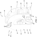
- FIG. 1 illustrates a mobile hose reel assembly 100.
- the mobile hose reel assembly 100 of the present disclosure may find application in various technical fields such as those belonging to firefighting, gardening, surface cleaning and the like.
- the mobile hose reel assembly 100 is easily and ergonomically moved or carried to different locations for fluid distribution intended for various applications.
- the mobile hose reel assembly 100 includes a housing 110.
- the housing 110 includes a first wall 112 and a second wall 114 coupled with and disposed opposite to the first wall 112.
- the first wall 112 and the second wall 114 may be temporarily or permanently attached to each other, such as by fasteners, screws, any suitable means as used or known in the art.
- first wall 112 and the second wall 114 are coupled to each other using a pair of brackets 111 such that one of the pair of brackets 111 couples the first wall 112 and the second wall 114 in a front portion 113 of the housing 110 of the mobile hose reel assembly 100 and the other bracket couples the first wall 112 and the second wall 114 in a back portion 113' of the housing 110 of the mobile hose reel assembly 100.
- the first wall 112 and the second wall 114 may have a circular, a rectangular or any other shape without limiting the scope of the disclosure. In a preferred embodiment of the present disclosure, the first wall 112 and the second wall 114 may have same shape and size. However, in some embodiments, the first wall 112 and the second wall 114 may have different shape and size as per the application requirement of the present disclosure.
- either the first wall 112 or the second wall 114 includes a plurality of windows 115 (or cut-outs) to view or access the inside of the housing 110 for maintenance purpose or the like.
- both the first wall 112 and the second wall 114 includes the plurality of windows 115.
- the plurality of windows 115 may have any number, shape, or size according to the functional requirements of the present disclosure.
- the plurality of windows 115 may be covered by a transparent door (not shown) such that the transparent door may be hingedly engaged with the first wall 112 and the second wall 114 and may be opened only when required. The transparent door may prevent unwanted entry of foreign elements to the inside of the housing 110.
- either the first wall 112 or the second wall 114 or both the first wall 112 and the second wall 114 includes a plurality of pre-drilled holes 117.
- the plurality of pre-drilled holes 117 may advantageously be used for fastening various accessories inside or outside of the housing 110 as per the application requirements.
- the pre-drilled holes 117 may be used to fasten an angle adjustable holder.
- the angle adjustable holder may allow ease of storing of different accessories such as nozzles, which may be removably attached to a hose 121 of the mobile hose reel assembly 100.
- the plurality of pre-drilled holes 117 prevent efforts by an operator to drill the holes 117 and further prevent unwanted or unintentional tampering of the first wall 112 and the second wall 114 of the housing 110.
- the number, shape, size, and positioning of the plurality of pre-drilled holes 117 may be pre-determined in the manufacturing facility based on possible application requirements, among other factors.
- the plurality of pre-drilled holes 117 may be provided with removable plugs such that the plugs may be removed from the selected holes 117 as and when required for further usage of the holes 117.
- first wall 112 and the second wall 114 of the housing 110 may be made from metal, fiberglass, or plastic. However, any other material may be used without limiting the scope of the present disclosure in any manner. Further, the first wall 112 and the second wall 114 may be manufactured from any known manufacturing means commonly utilized in the related art.
- the housing 110 further includes a handle portion 116 coupled with the first wall 112 and the second wall 114.
- the handle portion 116 includes a handle 118 and a connecting portion 119.
- the handle 118 may be connected to the connecting portion 119 by any means known in the art.
- the handle 118 includes a protrusion on each side of the handle such that each of the protrusion is inserted in a corresponding slot provided on each side of the connection portion 119.
- the protrusion and slot provide secure attachment between the handle 118 and the connecting portion 119 of the handle portion 116.
- the handle portion 116 may be coupled with the first wall 112 and the second wall 114 by any means known and understood in the related art without posing any limitation to the scope of the present disclosure.
- the first wall 112, second wall 144 and the handle portion 116 when coupled together form the housing 110 of the mobile hose reel assembly 100.
- the operator may simply carry the mobile hose reel assembly 100 from one location to the other by grasping the handle 118 of the housing 110.
- the handle 118 may be defined as an inverted U-shaped portion.
- the handle 118 may have any other shape as well without limiting the scope of the present disclosure.
- the handle 118 may be pivotally secured to the connecting portion 119 of the handle portion 116.
- the pivotable handle 118 may make it easier, safer to put down and pick up the mobile hose reel assembly 100 , such as from the ground surface (not shown).
- the pivotable handle 118 may be turned up while the mobile hose reel assembly 100 is in a grounded position leading to a convenient access for different individuals.
- the pivotable handle 118 may also make the mobile hose reel assembly 100 more compact for packaging, storage, and travel.
- the handle 118 may include a locking mechanism to lock the handle 118 in the pivotable position. The locking mechanism may provide a safe and trouble-free operation by disallowing any accidental movement of the pivotable handle 118.
- the handle 118 may be telescopic handle to allow a change in length thereof, and to further improve the ergonomics while picking up the mobile hose reel assembly 100.
- the handle 118 may include a grip portion such that the grasping of the grip portion of the handle 118 may provide better hold and safe working, movability of the mobile hose reel assembly 100 between locations.
- the material used for the grip portion may preferably be, but need not necessarily, PVC or nitrile rubber, or any other plastic or polymer to suit application needs.
- the housing 110 may include one or more wheels not shown.
- the one or more may preferably be provided proximate to the bottom portion of the housing 110 by any means known in the related art.
- the one or more wheels may ease support and movement of the mobile hose reel assembly 100 on the ground surface or improve portability between different locations/installations.
- the one or more wheels may be of any size, shape, type to facilitate easy and convenient movement of the mobile hose reel assembly 100 on the ground surface or for any other application requirements.
- the one or more wheels may be caster wheels.
- the caster wheels may help to easily manipulate the mobile hose reel assembly 100 on the ground surface.
- the one or more wheels may be powered by an electric motor (not shown), or any other powering means.
- the one or more wheels may be removably coupled with the housing 110.
- the one or more wheels may be removable to allow easy servicing, or even replacement, of the one or more wheels. Further, the removable feature of the one or more wheels may make the mobile hose reel assembly 100 more compact for packaging.
- the housing 110 as illustrated in FIG. 1 further includes a hose reel module 120 housed within the housing 110.
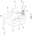
- the hose reel module 120 of the present disclosure is illustrated in detail in FIGS. 2 and 3 .
- the hose reel module 120 includes a pair of side walls 123 coupled with and disposed opposite to each other.
- the pair of side walls 123 may be temporarily or permanently attached to each other, such as by fasteners, screws, any suitable means as used or known in the art.
- the pair of side walls 123 are coupled to each other using a pair of brackets 125 such that one of the pair of brackets 125 couples the pair of side walls 123 in a front portion 127 of the hose reel module 120 of the mobile hose reel assembly 100 and the other bracket couples the pair of side walls 123 in a back portion 127' of the hose reel module 120 of the mobile hose reel assembly 100.
- the pair of side walls 123 are additionally coupled by a bracket 125' to impart more strength to the coupling between the pair of side walls 123.
- the hose reel module 120 includes an intermediate portion 128 disposed between and coupled with the pair of side walls 123.
- the intermediate portion 128 is coupled with the pair of side walls 123 by any means known and understood in the related art.
- the intermediate portion 128 is coupled with the connection portion 119 of the handle portion 116 of the housing 110.
- the coupling between the intermediate portion 128 and the connection portion 119 is such that the hose reel module 120 is adapted to exhibit a rocking motion relative to the housing 110.
- the hose reel module 120 is adapted to swivel relative to the housing 110.
- the hose reel module 120 is adapted to oscillate relative to the housing 110.
- the hose reel module 120 is adapted to exhibit a pendulum like motion relative to the housing 110 .
- the hose reel module 120 may hang within the housing 110 such that a bottom portion of the hose reel module 120 remains above the pair of brackets 111 .
- the rocking motion of the hose reel module 120 may preferably be limited proximate to the front portion 113 and back portion 113' of the housing 110. The rocking motion of the hose reel module 120 may be limited such that hose reel module 120 does not injure the operator standing close to the mobile hose reel assembly 100 or holding the mobile hose reel assembly 100 upon exhibiting the rocking motion.
- the hose reel module 120 may hang within the housing 110 such that a bottom portion of the hose reel module 120 is at the same level as the pair of brackets 111 .
- the rocking motion of the hose reel module 120 may be limited within the front portion 113 and back portion 113' of the housing 110 such that the hose reel module 120 does not collide with the pair of brackets 111 thereby reducing the service life of the mobile hose reel module 100 .
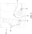
- the hose reel module 120 may include a pair of protrusions 132 (as shown in FIG. 4 ) such that the pair of protrusions 132 protrude in one of the plurality of windows 115 provided in the first wall 112 and the corresponding window 115 on the second wall 114 of the housing 110.
- the window 115 then defines the extent to which the hose reel module 120 may exhibit the rocking or swiveling motion within the housing 110.
- the hose reel module 120 may be manufactured from same material as used with the manufacturing of housing 110. In some embodiments, the hose reel module 120 may be manufactured from different material that that used with the manufacture of the housing 110. In some embodiments, the shape of the pair of side walls 123 is similar to the shape of the first wall 112 and the second wall 114 of the housing 110. However, in some embodiments, the shape of the pair of side walls 123 is different from the shape of the first wall 112 and the second wall 114 of the housing 110.
- the hose reel module 120 includes a hose reel 122 , a drive motor 124 operatively coupled to the hose reel 122 and a transmission mechanism 126 adapted to transmit the motion of the drive motor 124 to the hose reel 122.
- the hose reel 122 , the drive motor 124 and the transmission mechanism 126 are mechanically linked to each other for working of the mobile hose reel assembly 100.
- the hose reel 122 may be confined within the pair of side walls 123 and the intermediate portion 128 of the hose reel module 120 by any means known and understood in the related art.
- the hose reel 122 may have any shape and size such that it may properly confine within the hose reel module 120 and may leave ample space for the set-up of other accessories within the hose reel module 120.
- the hose reel 122 may preferably be cylindrical in shape.
- the hose reel 122 may be made from metal, fiberglass, or plastic.
- the hose reel 122 may be spring driven, hand-crank driven, or motor driven. However, in the preferred embodiment of the present disclosure, the hose reel 122 is motor driven, as already described above.
- the hose reel 122 stores the hose 121 for further usage with various industrial and domestic applications.
- the drive motor 124 may be a hydraulic motor or an electric motor. However, for the purpose of the present disclosure, the drive motor 124 is the electric motor. The electric motor may further be selected from a DC motor, an AC motor, a stepper motor, a brushless motor, a hysteresis motor, and the like considering the application requirements among other factors.
- the drive motor 124 is coupled to the pair of side walls 123 of the hose reel module 120 proximate the font portion 127 of the hose reel module 120. However, the drive motor 124 may be positioned at a different location within the hose reel module 120 as per the application requirement, space constraints, among other factors.
- the drive motor 124 is adapted to wind and unwind the hose 121 housed on the hose reel 122 by changing the direction of rotation of the drive motor 124.
- the direction of rotation of the drive motor 124 may be achieved by any means known in the related art.
- the drive motor 124 is selectively activated and deactivated based on the rocking motion of the hose reel module 120 relative to the housing 110.
- the drive motor 124 transmits the rotatory motion to the hose reel 122 via the transmission mechanism 126.
- the transmission mechanism 126 adapted to transmit the motion of the drive motor 124 to the hose reel 122 is a gear mechanism.
- the transmission mechanism 126 adapted to transmit the motion of the drive motor 124 to the hose reel 122 is a belt-drive mechanism. Either of the gear mechanism or the belt-drive mechanism may be used as per the application requirements, space constraint, maintenance, life-expectancy, among other factors.
- the transmission mechanism 126 is covered or locked inside a transparent cover 130 (as shown in FIG. 2 ) to prevent the transmission mechanism 126 from any possible damage due to the housing 110 , entry of foreign elements and the like.
- the operator connects the hose 121 of the hose reel 122 with the fluid source and walks away from the fluid source to the fluid distribution area.
- the operator carries or moves the mobile hose reel assembly 100 away from the fluid source once the hose 121 is connected to the fluid source. This results in low traction or pulling or tensile force by the hose 121 on the hose reel 122 (or the hose reel module 120 ).
- the traction force on the hose reel 122 (or the hose reel module 120 ) causes the hose reel module 120 to exhibit the rocking motion relative to the housing 110.
- the hose reel module 120 tends to swivel towards a hose outlet 129 of the mobile hose reel assembly 100 when the tensile or the traction force acts on the hose reel 122 or the hose reel module 120.
- the rocking motion of the hose reel module 120 may be detected by control electronics (not shown) provided with the mobile hose reel assembly 100 such that the control electronics activates the drive motor 124 for unwinding of the hose 121 from the hose reel 122.
- control electronics (not shown) provided with the mobile hose reel assembly 100 such that the control electronics activates the drive motor 124 for unwinding of the hose 121 from the hose reel 122.
- This is relatively a simple method to activate the drive motor 124 for unwinding process of the hose 121 when compared with the prior art methods, which involve measurement of tension value of the hose 121 by a sensor and further communication of the tension value measured by the sensor with the control electronics, which further based on stored set of algorithms decides upon when to activate or deactivate the drive motor 124.
- the present disclosure does not involve measurement of the tension and activates the drive motor 124 upon detection of the rocking motion of the hose reel module 120.
- the drive motor 124 once activated, relieves the tension in the hose 121 and the operator easily maneuvers around one or more obstacles in the fluid distribution area without the hose 121 getting caught or stuck with the one or more obstacles such as, but not limited to, trees, planting pots, and the like, thereby improving the overall efficiency of the mobile hose reel assembly 100. Further, when there is no traction force on the hose 121 , the hose reel module 120 returns back to the original position such that the drive motor 124 is automatically deactivated.
- the drive motor 124 is selectively activated and deactivated by a switch 134.
- the drive motor 124 may be manually activated or deactivated by pressing the switch 134 while carrying the mobile hose reel assembly 100.
- the switch 134 may be particularly advantageous in case of failure of electronics associated with detecting the rocking movement of the hose reel module 120. Further, the switch 134 is inexpensive, compact, and easily available for use with various applications.
- the drive motor 124 is selectively activated and deactivated by detecting an angle of the hose 121 winded on the hose reel 122.
- the hose 121 may undergo change in angle (or orientation) relative to the hose reel module 120 upon exposure to tensile force or traction force experienced for example, when the hose 121 is coupled to the fluid source.
- the change in angle may be detected or measured by any means known in the art and may be used to selectively activated and deactivate the drive motor 124 for smooth functioning of the mobile hose reel assembly 100.
- the mobile hose reel assembly 100 includes a pair of guide rolls 131, 133 for guiding the hose 121 (as shown in FIGS. 1 , 2 and 3 ) during the winding and unwinding operation of the hose 121.
- the pair of guide rolls 131, 133 allows efficient winding and unwinding of the hose 121.
- the pair of guide rolls 131, 133 prevent chaotic hose winding or hose entanglement inside the hose reel 122 or the hose reel module 120.
- the pair of guide rolls 131, 133 are placed near the hose outlet 129 of the hose reel module 120.
- the hose 121 gets clamped between the pair of guide rolls 131, 133 and during winding or unwinding, at least one of the guide rolls from the pair of guide rolls 131, 133 is driven by the drive motor 124 to pull out or pull in the hose 121 from the hose reel module 120.
- the drive motor 124 is installed in the guide roll 133.
- the drive motor 124 may be installed in the guide roll 131 depending upon the arrangement of the transmission mechanism 126 , among other factors.
- the pair of guide rolls 131, 133 and the hose reel 122 may be simultaneously driven during winding and unwinding by installing equalizing or differential gear set between the pair of guide rolls 131, 133 and the hose reel 122.
- a speed of rotation of the hose reel 122 is adapted to be equivalent to walking speed of the operator when the amount of hose 121 on the hose reel 122 is changing during unwinding.
- the operator may fluidly couple the hose 121 with the fluid source and walk away from the fluid source for unwinding of the hose 121.
- the speed of rotation of the hose reel 122 may change with the changing radius of the hose 121 winded on the hose reel 122 and may differ from the constant speed of the hose 121 or walking speed of the operator. This may lead to cumbersome unwinding of the hose 121.
- the speed of rotation of the hose reel 122 may thus be controlled using a set of equalizing or differential gear set.
- the mobile hose reel assembly 100 includes a slider 135 adapted to regulate the speed of rotation of the hose reel 122.
- the slider 135 may be used to regulate the speed of rotation of the hose reel such that the tension in the hose 121 is always relieved during the unwinding operation.
- the slider 135 disengages the transmission of power between the drive motor 124 and the hose reel 122.
- the slider 135 may function to change the direction of operation of the drive motor 124.
- the present disclosure provides the mobile hose reel assembly 100 that is moved or carried to different locations for fluid distribution intended for various industrial and domestic applications.
- the mobile hose reel assembly 100 is simple and ergonomic for usage by an operator.
- the mobile hose reel assembly 100 is compact and includes the hose reel module 120 that advantageously exhibits the rocking motion within the housing 110 of the mobile hose reel assembly 100.
- the hose reel module 120 includes the hose reel 122 and the drive motor 124 (say the electric motor) mechanically coupled with the hose reel 122.
- the drive motor 124 facilitates automatic unwinding or winding of the hose 121 of the hose reel assembly 100.
- the drive motor 124 is selectively activated and deactivated based on the rocking motion of the hose reel 122 module relative to the housing 110.
- the hose reel module 120 tends to swivel towards the hose outlet 129 of the mobile hose reel assembly 100 when the tensile or traction force acts on the hose reel 122 or the hose reel module 120 (possibly due to the fluid connection of the hose 121 with the fluid source). This is detected by control electronics provided with the mobile hose reel assembly 100 and the drive motor 124 is automatically activated for unwinding of the hose 121.
- the drive motor 124 further relieves the tension in the hose 121 such that the operator easily maneuvers around one or more obstacles in a fluid distribution area without the hose 121 getting caught or stuck with the one or more obstacles such as, but not limited to, trees, planting pots, and the like, thereby improving the overall efficiency of the mobile hose reel assembly 100.
Landscapes
- Engineering & Computer Science (AREA)
- Mechanical Engineering (AREA)
- Storing, Repeated Paying-Out, And Re-Storing Of Elongated Articles (AREA)
Abstract
Description
- The present disclosure relates to a hose reel assembly. More specifically, the present disclosure relates to a mobile hose reel assembly, which allows efficient and user-friendly operation.
- A hose reel assembly is used to provide a flow of fluid, such as water, in spaces, such as lawns, parks, and the like. Generally, the hose reel assembly is fixedly mounted on a wall, or a ground. However, such hose reel assemblies are non-ergonomic and have limited reach due to a stationary set-up.
- An improvement to the historically (or conventionally) used hose reel assemblies is a mobile hose reel assembly. The mobile hose reel assembly is portable and may be carried from one location to another for various domestic as well as industrial applications.
- The mobile hose reel assembly may be fluidly coupled with a fluid source (say a water tap) and may further be taken to a garden, or the like for supplying fluid received from the fluid source. While moving away from the fluid source, a hose of the mobile hose reel assembly fluidly coupled with the fluid source may unwind from a corresponding (or associated) hose reel due to hose tension. The hose tension may be generated due to fluid coupling between the fluid source and the hose.
- Further, while moving away from the fluid source, the unwinded hose touches every obstacle in the way, especially, in balconies, terraces, small gardens or the like and may even get stuck with the obstacles due to the tension in the hose. This may lead to a cumbersome experience for an operator of the hose reel assembly. Hence, an improved mobile hose reel assembly is required that may be capable of releasing the hose tension during the unwinding operation of the hose reel and may be easily maneuvered around obstacles.
- An example of a hose reel assembly is provided in Korean patent
KR 10 2127 318 - Thus, there is a need of an improved hose reel assembly which has a simple operational design architecture and allows easy, portable, and ergonomic operation.
- In view of the above, it is an objective of the present invention to solve or at least reduce the drawbacks discussed above. The objective is at least partially achieved by a mobile hose reel assembly. The mobile hose reel assembly includes a housing. The housing includes a first wall, a second wall coupled with and disposed opposite to the first wall and a handle portion coupled with the first wall and the second wall. The housing further includes a hose reel module housed within the housing. The hose reel module includes a hose reel, a drive motor operatively coupled to the hose reel and a transmission mechanism adapted to transmit the motion of the drive motor to the hose reel. The mobile hose reel assembly is characterized in that the hose reel module is adapted to exhibit a rocking motion relative to the housing. Further, the drive motor is selectively activated and deactivated based on the rocking motion of the hose reel module relative to the housing.
- Thus, the present disclosure provides the mobile hose reel assembly that is moved or carried to different locations for fluid distribution intended for various industrial and domestic applications. The mobile hose reel assembly is simple and ergonomic for usage by an operator. The mobile hose reel assembly is compact and includes the hose reel module that advantageously exhibits the rocking motion within the housing of the mobile hose reel assembly. The hose reel module includes the hose reel and the drive motor (say an electric motor) mechanically coupled with the hose reel. The drive motor facilitates automatic unwinding of a hose of the hose reel assembly. The drive motor is selectively activated and deactivated based on the rocking motion of the hose reel module relative to the housing. The hose reel module tends to swivel towards a hose outlet of the mobile hose reel assembly when a tensile force acts on the hose reel or the hose reel module (possibly due to the fluid connection of the hose with a fluid source). This is detected by control electronics provided with the mobile hose reel assembly and the drive motor is automatically activated for unwinding of the hose. The drive motor further relieves the tension in the hose such that the operator easily maneuvers around one or more obstacles in a fluid distribution area without the hose getting caught or stuck with the one or more obstacles such as, but not limited to, trees, planting pots, and the like, thereby improving the overall efficiency of the mobile hose reel assembly.
- According to an embodiment of the present disclosure, the drive motor is selectively activated and deactivated by a switch. The drive motor may be manually activated or deactivated by the switch as per the application requirement. The drive motor may be activated or deactivated in case of failure of electronics associated with detecting the rocking movement of the hose reel module. Further, the switches are inexpensive, compact, and easily available for use with various applications.
- According to an embodiment of the present disclosure, the drive motor is selectively activated and deactivated by detecting an angle of a hose winded on the hose reel. The hose may undergo change in angle (or orientation) relative to the hose reel module upon exposure to tensile force experienced for example, when the hose is coupled to the fluid source. The change in angle may be detected or measured by any means known in the art and may be used to selectively activate and deactivate the drive motor for smooth functioning of the mobile hose reel assembly.
- According to an embodiment of the present disclosure, the transmission mechanism adapted to transmit the motion of the drive motor to the hose reel is a gear mechanism. However, in some embodiments, the transmission mechanism adapted to transmit the motion of the drive motor to the hose reel is a belt-drive mechanism. Either of the gear mechanism or the belt-drive mechanism may be used as per the application requirements, space constraint, maintenance, life-expectancy, among other factors.
- According to an embodiment of the present disclosure, a speed of the hose reel is adapted to be equivalent to walking speed of an operator when the amount of hose on the hose reel is changing during unwinding. The operator may fluidly couple the hose with the fluid source and walk away from the fluid source for unwinding of the hose. The speed of rotation of the hose reel may change with the changing radius of the hose winded on the hose reel and may differ from the constant speed of the hose or walking speed of the operator. This may lead to cumbersome unwinding of the hose. The speed of rotation of the hose reel may thus be controlled using a set of equalizing or differential gear set.
- According to an embodiment of the present disclosure, the mobile hose reel assembly includes a pair of guide rolls for guiding the hose during the winding and unwinding operation of the hose. The pair of guide rolls allows efficient winding and unwinding of the hose. The pair of guide rolls prevent chaotic hose winding or hose entanglement inside the hose reel.
- According to an embodiment of the present disclosure, the mobile hose reel assembly includes a slider adapted to regulate the speed of the hose reel. The slider may be used to regulate the speed of the hose reel such that the tension in the hose is always relieved during the unwinding operation. In some embodiments of the present disclosure, the slider disengages the transmission of power between the drive motor and the hose reel.
- According to an embodiment of the present disclosure, the at least one of the guide rolls from the pair of guide rolls is driven by the drive motor. This improves the unwinding of the hose from the hose reel. It is obvious that the hose reel and at least one of the guide rolls can be coupled and thus driven together but it has not to be the case. In one embodiment it is also possible to only drivingly couple hose reel and at least one of the guide rolls only when winding or when unwinding the hose. In the situation where there is no drivingly coupling necessary it is possible to employ a free wheel clutch or the like.
- According to an embodiment of the present disclosure, the pair of guide rolls and the hose reel are simultaneously driven during winding and unwinding by installing an equalizing or differential gear set between the pair of guide rolls and the hose reel. It is obvious that alternatively or in addition to this gear set the simultaneous drive can also be achieved by sensing the hose speed and controlling the speed or speeds of revolution accordingly. With the help of this an entanglement of the hose during usage of the tool can widely be avoided.
- Other features and aspects of this invention will be apparent from the following description and the accompanying drawings.
- The invention will be described in more detail with reference to the enclosed drawings, wherein:
-
FIG. 1 shows a perspective view of a mobile hose reel assembly, in accordance with an aspect of the present disclosure; -
FIG. 2 shows a perspective view of a hose reel module of the mobile hose reel assembly ofFIG. 1 , in accordance with an aspect of the present disclosure; -
FIG. 3 shows another perspective view of the hose reel module ofFIG. 2 , in accordance with an aspect of the present disclosure; -
FIG. 4 shows an enlarged view of a portion of the mobile hose reel assembly ofFIG. 1 , in accordance with an aspect of the present disclosure; and -
FIG. 5 shows a detailed internal view of a portion of the mobile hose reel assembly ofFIG. 1 , in accordance with an aspect of the present disclosure. - The present invention will be described more fully hereinafter with reference to the accompanying drawings, in which example embodiments of the invention incorporating one or more aspects of the present invention are shown. This invention may, however, be embodied in many different forms and should not be construed as limited to the embodiments set forth herein; rather, these embodiments are provided so that this disclosure will be thorough and complete, and will fully convey the scope of the invention to those skilled in the art. For example, one or more aspects of the present invention may be utilized in other embodiments and even other types of structures and/or methods. In the drawings, like numbers refer to like elements.
- Certain terminology is used herein for convenience only and is not to be taken as a limitation on the invention. For example, "upper", "lower", "front", "rear", "side", "longitudinal", "lateral", "transverse", "upwards", "downwards", "forward", "backward", "sideward", "left," "right," "horizontal," "vertical," "upward", "inner", "outer", "inward", "outward", "top", "bottom", "higher", "above", "below", "central", "middle", "intermediate", "between", "end", "adjacent", "proximate", "near", "distal", "remote", "radial", "circumferential", or the like, merely describe the configuration shown in the Figures. Indeed, the components may be oriented in any direction and the terminology, therefore, should be understood as encompassing such variations unless specified otherwise.
-
FIG. 1 illustrates a mobilehose reel assembly 100. The mobilehose reel assembly 100 of the present disclosure may find application in various technical fields such as those belonging to firefighting, gardening, surface cleaning and the like. The mobilehose reel assembly 100 is easily and ergonomically moved or carried to different locations for fluid distribution intended for various applications. - The mobile
hose reel assembly 100 includes ahousing 110. Thehousing 110 includes afirst wall 112 and asecond wall 114 coupled with and disposed opposite to thefirst wall 112. Thefirst wall 112 and thesecond wall 114 may be temporarily or permanently attached to each other, such as by fasteners, screws, any suitable means as used or known in the art. However, for the purpose of present disclosure, thefirst wall 112 and thesecond wall 114 are coupled to each other using a pair ofbrackets 111 such that one of the pair ofbrackets 111 couples thefirst wall 112 and thesecond wall 114 in afront portion 113 of thehousing 110 of the mobilehose reel assembly 100 and the other bracket couples thefirst wall 112 and thesecond wall 114 in aback portion 113' of thehousing 110 of the mobilehose reel assembly 100. - The
first wall 112 and thesecond wall 114 may have a circular, a rectangular or any other shape without limiting the scope of the disclosure. In a preferred embodiment of the present disclosure, thefirst wall 112 and thesecond wall 114 may have same shape and size. However, in some embodiments, thefirst wall 112 and thesecond wall 114 may have different shape and size as per the application requirement of the present disclosure. - In some embodiments, either the
first wall 112 or thesecond wall 114 includes a plurality of windows 115 (or cut-outs) to view or access the inside of thehousing 110 for maintenance purpose or the like. In some embodiments, both thefirst wall 112 and thesecond wall 114 includes the plurality ofwindows 115. The plurality ofwindows 115 may have any number, shape, or size according to the functional requirements of the present disclosure. In some embodiments, the plurality ofwindows 115 may be covered by a transparent door (not shown) such that the transparent door may be hingedly engaged with thefirst wall 112 and thesecond wall 114 and may be opened only when required. The transparent door may prevent unwanted entry of foreign elements to the inside of thehousing 110. - Further, in some embodiments of the present disclosure, either the
first wall 112 or thesecond wall 114 or both thefirst wall 112 and thesecond wall 114 includes a plurality ofpre-drilled holes 117. The plurality ofpre-drilled holes 117 may advantageously be used for fastening various accessories inside or outside of thehousing 110 as per the application requirements. For example, thepre-drilled holes 117 may be used to fasten an angle adjustable holder. The angle adjustable holder may allow ease of storing of different accessories such as nozzles, which may be removably attached to ahose 121 of the mobilehose reel assembly 100. - The plurality of
pre-drilled holes 117 prevent efforts by an operator to drill theholes 117 and further prevent unwanted or unintentional tampering of thefirst wall 112 and thesecond wall 114 of thehousing 110. The number, shape, size, and positioning of the plurality ofpre-drilled holes 117 may be pre-determined in the manufacturing facility based on possible application requirements, among other factors. In some embodiments, the plurality ofpre-drilled holes 117 may be provided with removable plugs such that the plugs may be removed from the selectedholes 117 as and when required for further usage of theholes 117. - In some embodiments, the
first wall 112 and thesecond wall 114 of thehousing 110 may be made from metal, fiberglass, or plastic. However, any other material may be used without limiting the scope of the present disclosure in any manner. Further, thefirst wall 112 and thesecond wall 114 may be manufactured from any known manufacturing means commonly utilized in the related art. - With continued reference to
FIG. 1 , thehousing 110 further includes ahandle portion 116 coupled with thefirst wall 112 and thesecond wall 114. Thehandle portion 116 includes ahandle 118 and a connectingportion 119. Thehandle 118 may be connected to the connectingportion 119 by any means known in the art. However, for the purpose of present disclosure, thehandle 118 includes a protrusion on each side of the handle such that each of the protrusion is inserted in a corresponding slot provided on each side of theconnection portion 119. The protrusion and slot provide secure attachment between thehandle 118 and the connectingportion 119 of thehandle portion 116. Further, thehandle portion 116 may be coupled with thefirst wall 112 and thesecond wall 114 by any means known and understood in the related art without posing any limitation to the scope of the present disclosure. Thus, thefirst wall 112, second wall 144 and thehandle portion 116 when coupled together form thehousing 110 of the mobilehose reel assembly 100. - The operator may simply carry the mobile
hose reel assembly 100 from one location to the other by grasping thehandle 118 of thehousing 110. In some embodiments, thehandle 118 may be defined as an inverted U-shaped portion. However, thehandle 118 may have any other shape as well without limiting the scope of the present disclosure. - In some embodiments, the
handle 118 may be pivotally secured to the connectingportion 119 of thehandle portion 116. The pivotable handle 118 may make it easier, safer to put down and pick up the mobilehose reel assembly 100, such as from the ground surface (not shown). The pivotable handle 118 may be turned up while the mobilehose reel assembly 100 is in a grounded position leading to a convenient access for different individuals. The pivotable handle 118 may also make the mobilehose reel assembly 100 more compact for packaging, storage, and travel. In some embodiments, thehandle 118 may include a locking mechanism to lock thehandle 118 in the pivotable position. The locking mechanism may provide a safe and trouble-free operation by disallowing any accidental movement of thepivotable handle 118. - In some embodiments, the
handle 118 may be telescopic handle to allow a change in length thereof, and to further improve the ergonomics while picking up the mobilehose reel assembly 100. In some embodiments, thehandle 118 may include a grip portion such that the grasping of the grip portion of thehandle 118 may provide better hold and safe working, movability of the mobilehose reel assembly 100 between locations. The material used for the grip portion may preferably be, but need not necessarily, PVC or nitrile rubber, or any other plastic or polymer to suit application needs. - In some embodiments, the
housing 110 may include one or more wheels not shown. The one or more may preferably be provided proximate to the bottom portion of thehousing 110 by any means known in the related art. The one or more wheels may ease support and movement of the mobilehose reel assembly 100 on the ground surface or improve portability between different locations/installations. In some embodiments, the one or more wheels may be of any size, shape, type to facilitate easy and convenient movement of the mobilehose reel assembly 100 on the ground surface or for any other application requirements. - In some embodiments, the one or more wheels may be caster wheels. The caster wheels may help to easily manipulate the mobile
hose reel assembly 100 on the ground surface. In some embodiments, the one or more wheels may be powered by an electric motor (not shown), or any other powering means. In some embodiments, the one or more wheels may be removably coupled with thehousing 110. The one or more wheels may be removable to allow easy servicing, or even replacement, of the one or more wheels. Further, the removable feature of the one or more wheels may make the mobilehose reel assembly 100 more compact for packaging. - The
housing 110 as illustrated inFIG. 1 further includes ahose reel module 120 housed within thehousing 110. Thehose reel module 120 of the present disclosure is illustrated in detail inFIGS. 2 and3 . Thehose reel module 120 includes a pair ofside walls 123 coupled with and disposed opposite to each other. The pair ofside walls 123 may be temporarily or permanently attached to each other, such as by fasteners, screws, any suitable means as used or known in the art. However, for the purpose of present disclosure, the pair ofside walls 123 are coupled to each other using a pair ofbrackets 125 such that one of the pair ofbrackets 125 couples the pair ofside walls 123 in afront portion 127 of thehose reel module 120 of the mobilehose reel assembly 100 and the other bracket couples the pair ofside walls 123 in aback portion 127' of thehose reel module 120 of the mobilehose reel assembly 100. The pair ofside walls 123 are additionally coupled by a bracket 125' to impart more strength to the coupling between the pair ofside walls 123. - Further, as illustrated in
FIGS. 2 and3 , thehose reel module 120 includes anintermediate portion 128 disposed between and coupled with the pair ofside walls 123. Theintermediate portion 128 is coupled with the pair ofside walls 123 by any means known and understood in the related art. Further, theintermediate portion 128 is coupled with theconnection portion 119 of thehandle portion 116 of thehousing 110. The coupling between theintermediate portion 128 and theconnection portion 119 is such that thehose reel module 120 is adapted to exhibit a rocking motion relative to thehousing 110. Thehose reel module 120 is adapted to swivel relative to thehousing 110. Thehose reel module 120 is adapted to oscillate relative to thehousing 110. Thehose reel module 120 is adapted to exhibit a pendulum like motion relative to thehousing 110. - In some embodiments, the
hose reel module 120 may hang within thehousing 110 such that a bottom portion of thehose reel module 120 remains above the pair ofbrackets 111. In such embodiments, the rocking motion of thehose reel module 120 may preferably be limited proximate to thefront portion 113 andback portion 113' of thehousing 110. The rocking motion of thehose reel module 120 may be limited such thathose reel module 120 does not injure the operator standing close to the mobilehose reel assembly 100 or holding the mobilehose reel assembly 100 upon exhibiting the rocking motion. - In some embodiments, the
hose reel module 120 may hang within thehousing 110 such that a bottom portion of thehose reel module 120 is at the same level as the pair ofbrackets 111. In such embodiments, the rocking motion of thehose reel module 120 may be limited within thefront portion 113 andback portion 113' of thehousing 110 such that thehose reel module 120 does not collide with the pair ofbrackets 111 thereby reducing the service life of the mobilehose reel module 100. - In some embodiments, the
hose reel module 120 may include a pair of protrusions 132 (as shown inFIG. 4 ) such that the pair ofprotrusions 132 protrude in one of the plurality ofwindows 115 provided in thefirst wall 112 and thecorresponding window 115 on thesecond wall 114 of thehousing 110. Thewindow 115 then defines the extent to which thehose reel module 120 may exhibit the rocking or swiveling motion within thehousing 110. - In some embodiments, the
hose reel module 120 may be manufactured from same material as used with the manufacturing ofhousing 110. In some embodiments, thehose reel module 120 may be manufactured from different material that that used with the manufacture of thehousing 110. In some embodiments, the shape of the pair ofside walls 123 is similar to the shape of thefirst wall 112 and thesecond wall 114 of thehousing 110. However, in some embodiments, the shape of the pair ofside walls 123 is different from the shape of thefirst wall 112 and thesecond wall 114 of thehousing 110. - With continued reference to
FIGS. 2 and3 , thehose reel module 120 includes ahose reel 122, adrive motor 124 operatively coupled to thehose reel 122 and atransmission mechanism 126 adapted to transmit the motion of thedrive motor 124 to thehose reel 122. Thehose reel 122, thedrive motor 124 and thetransmission mechanism 126 are mechanically linked to each other for working of the mobilehose reel assembly 100. The mechanically linked parts as defined above, collectively work to wind and unwind thehose 121 stored or winded on thehose reel 122 for various non-limiting fluid distribution applications. - The
hose reel 122 may be confined within the pair ofside walls 123 and theintermediate portion 128 of thehose reel module 120 by any means known and understood in the related art. Thehose reel 122 may have any shape and size such that it may properly confine within thehose reel module 120 and may leave ample space for the set-up of other accessories within thehose reel module 120. Thehose reel 122 may preferably be cylindrical in shape. Thehose reel 122 may be made from metal, fiberglass, or plastic. Thehose reel 122 may be spring driven, hand-crank driven, or motor driven. However, in the preferred embodiment of the present disclosure, thehose reel 122 is motor driven, as already described above. Thehose reel 122 stores thehose 121 for further usage with various industrial and domestic applications. - Further, the
drive motor 124 may be a hydraulic motor or an electric motor. However, for the purpose of the present disclosure, thedrive motor 124 is the electric motor. The electric motor may further be selected from a DC motor, an AC motor, a stepper motor, a brushless motor, a hysteresis motor, and the like considering the application requirements among other factors. Thedrive motor 124 is coupled to the pair ofside walls 123 of thehose reel module 120 proximate thefont portion 127 of thehose reel module 120. However, thedrive motor 124 may be positioned at a different location within thehose reel module 120 as per the application requirement, space constraints, among other factors. Thedrive motor 124 is adapted to wind and unwind thehose 121 housed on thehose reel 122 by changing the direction of rotation of thedrive motor 124. The direction of rotation of thedrive motor 124 may be achieved by any means known in the related art. Further, thedrive motor 124 is selectively activated and deactivated based on the rocking motion of thehose reel module 120 relative to thehousing 110. - The
drive motor 124 transmits the rotatory motion to thehose reel 122 via thetransmission mechanism 126. In some embodiments, thetransmission mechanism 126 adapted to transmit the motion of thedrive motor 124 to thehose reel 122 is a gear mechanism. However, in some embodiments, thetransmission mechanism 126 adapted to transmit the motion of thedrive motor 124 to thehose reel 122 is a belt-drive mechanism. Either of the gear mechanism or the belt-drive mechanism may be used as per the application requirements, space constraint, maintenance, life-expectancy, among other factors. Further, in some embodiments of the present disclosure, thetransmission mechanism 126 is covered or locked inside a transparent cover 130 (as shown inFIG. 2 ) to prevent thetransmission mechanism 126 from any possible damage due to thehousing 110, entry of foreign elements and the like. - In operation, the operator connects the
hose 121 of thehose reel 122 with the fluid source and walks away from the fluid source to the fluid distribution area. The operator carries or moves the mobilehose reel assembly 100 away from the fluid source once thehose 121 is connected to the fluid source. This results in low traction or pulling or tensile force by thehose 121 on the hose reel 122 (or the hose reel module 120). The traction force on the hose reel 122 (or the hose reel module 120) causes thehose reel module 120 to exhibit the rocking motion relative to thehousing 110. Thehose reel module 120 tends to swivel towards ahose outlet 129 of the mobilehose reel assembly 100 when the tensile or the traction force acts on thehose reel 122 or thehose reel module 120. - The rocking motion of the
hose reel module 120 may be detected by control electronics (not shown) provided with the mobilehose reel assembly 100 such that the control electronics activates thedrive motor 124 for unwinding of thehose 121 from thehose reel 122. This is relatively a simple method to activate thedrive motor 124 for unwinding process of thehose 121 when compared with the prior art methods, which involve measurement of tension value of thehose 121 by a sensor and further communication of the tension value measured by the sensor with the control electronics, which further based on stored set of algorithms decides upon when to activate or deactivate thedrive motor 124. The present disclosure does not involve measurement of the tension and activates thedrive motor 124 upon detection of the rocking motion of thehose reel module 120. - The
drive motor 124 once activated, relieves the tension in thehose 121 and the operator easily maneuvers around one or more obstacles in the fluid distribution area without thehose 121 getting caught or stuck with the one or more obstacles such as, but not limited to, trees, planting pots, and the like, thereby improving the overall efficiency of the mobilehose reel assembly 100. Further, when there is no traction force on thehose 121, thehose reel module 120 returns back to the original position such that thedrive motor 124 is automatically deactivated. - In some embodiments of the present disclosure, as illustrated in
FIG. 4 , thedrive motor 124 is selectively activated and deactivated by aswitch 134. Thedrive motor 124 may be manually activated or deactivated by pressing theswitch 134 while carrying the mobilehose reel assembly 100. Theswitch 134 may be particularly advantageous in case of failure of electronics associated with detecting the rocking movement of thehose reel module 120. Further, theswitch 134 is inexpensive, compact, and easily available for use with various applications. - In some embodiments of the present disclosure, the
drive motor 124 is selectively activated and deactivated by detecting an angle of thehose 121 winded on thehose reel 122. Thehose 121 may undergo change in angle (or orientation) relative to thehose reel module 120 upon exposure to tensile force or traction force experienced for example, when thehose 121 is coupled to the fluid source. The change in angle may be detected or measured by any means known in the art and may be used to selectively activated and deactivate thedrive motor 124 for smooth functioning of the mobilehose reel assembly 100. - Further, as illustrated in
FIG. 5 , the mobilehose reel assembly 100 includes a pair of guide rolls 131, 133 for guiding the hose 121 (as shown inFIGS. 1 ,2 and3 ) during the winding and unwinding operation of thehose 121. The pair of guide rolls 131, 133 allows efficient winding and unwinding of thehose 121. The pair of guide rolls 131, 133 prevent chaotic hose winding or hose entanglement inside thehose reel 122 or thehose reel module 120. The pair of guide rolls 131, 133 are placed near thehose outlet 129 of thehose reel module 120. - The
hose 121 gets clamped between the pair of guide rolls 131, 133 and during winding or unwinding, at least one of the guide rolls from the pair of guide rolls 131, 133 is driven by thedrive motor 124 to pull out or pull in thehose 121 from thehose reel module 120. In the embodiment of the present disclosure, thedrive motor 124 is installed in theguide roll 133. However, thedrive motor 124 may be installed in theguide roll 131 depending upon the arrangement of thetransmission mechanism 126, among other factors. Further, in some embodiments, the pair of guide rolls 131, 133 and thehose reel 122 may be simultaneously driven during winding and unwinding by installing equalizing or differential gear set between the pair of guide rolls 131, 133 and thehose reel 122. - In some embodiments, a speed of rotation of the
hose reel 122 is adapted to be equivalent to walking speed of the operator when the amount ofhose 121 on thehose reel 122 is changing during unwinding. The operator may fluidly couple thehose 121 with the fluid source and walk away from the fluid source for unwinding of thehose 121. The speed of rotation of thehose reel 122 may change with the changing radius of thehose 121 winded on thehose reel 122 and may differ from the constant speed of thehose 121 or walking speed of the operator. This may lead to cumbersome unwinding of thehose 121. The speed of rotation of thehose reel 122 may thus be controlled using a set of equalizing or differential gear set. - Further, as illustrated in
FIGS. 2 ,3 and5 of the present disclosure, the mobilehose reel assembly 100 includes aslider 135 adapted to regulate the speed of rotation of thehose reel 122. Theslider 135 may be used to regulate the speed of rotation of the hose reel such that the tension in thehose 121 is always relieved during the unwinding operation. In some embodiments of the present disclosure, theslider 135 disengages the transmission of power between thedrive motor 124 and thehose reel 122. In some embodiments of the present disclosure, theslider 135 may function to change the direction of operation of thedrive motor 124. - Thus, the present disclosure provides the mobile
hose reel assembly 100 that is moved or carried to different locations for fluid distribution intended for various industrial and domestic applications. The mobilehose reel assembly 100 is simple and ergonomic for usage by an operator. The mobilehose reel assembly 100 is compact and includes thehose reel module 120 that advantageously exhibits the rocking motion within thehousing 110 of the mobilehose reel assembly 100. Thehose reel module 120 includes thehose reel 122 and the drive motor 124 (say the electric motor) mechanically coupled with thehose reel 122. Thedrive motor 124 facilitates automatic unwinding or winding of thehose 121 of thehose reel assembly 100. Thedrive motor 124 is selectively activated and deactivated based on the rocking motion of thehose reel 122 module relative to thehousing 110. Thehose reel module 120 tends to swivel towards thehose outlet 129 of the mobilehose reel assembly 100 when the tensile or traction force acts on thehose reel 122 or the hose reel module 120 (possibly due to the fluid connection of thehose 121 with the fluid source). This is detected by control electronics provided with the mobilehose reel assembly 100 and thedrive motor 124 is automatically activated for unwinding of thehose 121. Thedrive motor 124 further relieves the tension in thehose 121 such that the operator easily maneuvers around one or more obstacles in a fluid distribution area without thehose 121 getting caught or stuck with the one or more obstacles such as, but not limited to, trees, planting pots, and the like, thereby improving the overall efficiency of the mobilehose reel assembly 100. - In the drawings and specification, there have been disclosed preferred embodiments and examples of the invention and, although specific terms are employed, they are used in a generic and descriptive sense only and not for the purpose of limitation of the scope of the invention being set forth in the following claims.
-
- 100
- Mobile Hose Reel Assembly
- 110
- Housing
- 111
- Bracket
- 112
- First Wall
- 113
- Front Portion
- 113'
- Back Portion
- 114
- Second Wall
- 115
- Windows
- 116
- Handle Portion
- 117
- Holes
- 118
- Handle
- 119
- Connecting Portion
- 120
- Hose Reel Module
- 121
- Hose
- 122
- Hose Reel
- 123
- Side Walls
- 124
- Drive Motor
- 125,125'
- Brackets
- 126
- Transmission Mechanism
- 127
- Front Portion
- 127'
- Back Portion
- 128
- Intermediate Portion
- 129
- Hose Outlet
- 130
- Transparent Cover
- 131
- Guide Roll
- 132
- Protrusions
- 133
- Guide Roll
- 134
- Switch
- 135
- Slider
Claims (10)
- A mobile hose reel assembly (100) comprising:a housing (110), wherein the housing (110) includes:a first wall (112);a second wall (114) coupled with and disposed opposite to the first wall (112); anda handle portion (116) coupled with the first wall (112) and the second wall (114);a hose reel module (120) housed within the housing (110), the hose reel module (120) including:a hose reel (122);a drive motor (124) operatively coupled to the hose reel (122); anda transmission mechanism (126) adapted to transmit the motion of the drive motor (124) to the hose reel (122);characterized in that:the hose reel module (120) is adapted to exhibit a rocking motion relative to the housing (110);the drive motor (124) is selectively activated and deactivated based on the rocking motion of the hose reel module (120) relative to the housing (110).
- The mobile hose reel assembly (100) of claim 1, wherein the drive motor (124) is selectively activated and deactivated by a switch (134).
- The mobile hose reel assembly (100) of any of the preceding claims, wherein the drive motor (124) is selectively activated and deactivated by detecting an angle of a hose (121) winded on the hose reel (122).
- The mobile hose reel assembly (100) of any of the preceding claims, wherein the transmission mechanism (126) adapted to transmit the motion of the drive motor (124) to the hose reel (122) is a gear mechanism.
- The mobile hose reel assembly (100) of any of the preceding claims, wherein the transmission mechanism (126) adapted to transmit the motion of the drive motor (124) to the hose reel (122) is a belt-drive mechanism.
- The mobile hose reel assembly (100) of any of the preceding claims, wherein a speed of the hose reel (122) is adapted to be equivalent to walking speed of an operator when the amount of hose (121) on the hose reel (122) is changing during unwinding.
- The mobile hose reel assembly (100) of any of the preceding claims, wherein the mobile hose reel assembly (100) includes a pair of guide rolls (131, 133) for guiding the hose (121) during the winding and unwinding operation of the hose (121).
- The mobile hose reel assembly (100) of any of the preceding claims, wherein the mobile hose reel assembly (100) includes a slider (135) adapted to regulate the speed of the hose reel (122).
- The mobile hose reel assembly (100) of any of the preceding claims, wherein at least one of the guide rolls from the pair of guide rolls (131), (133) is driven by the drive motor (124).
- The mobile hose reel assembly (100) of any of the preceding claims, wherein the pair of guide rolls (131, 133) and the hose reel (122) are simultaneously driven during winding and unwinding by installing an equalizing or differential gear set between the pair of guide rolls (131, 133) and the hose reel (122).
Priority Applications (7)
| Application Number | Priority Date | Filing Date | Title |
|---|---|---|---|
| FIEP22176338.6T FI4286311T3 (en) | 2022-05-31 | 2022-05-31 | Hose reel assembly |
| EP22176338.6A EP4286311B1 (en) | 2022-05-31 | 2022-05-31 | Hose reel assembly |
| PL22176338.6T PL4286311T3 (en) | 2022-05-31 | 2022-05-31 | Hose reel assembly |
| US18/080,826 US12522467B2 (en) | 2022-05-31 | 2022-12-14 | Hose reel assembly |
| CN202211673897.5A CN117142268B (en) | 2022-05-31 | 2022-12-26 | Hose reel assembly |
| CN202223482725.8U CN219429405U (en) | 2022-05-31 | 2022-12-26 | Hose reel assembly |
| TW111150401A TW202348537A (en) | 2022-05-31 | 2022-12-28 | Hose reel assembly |
Applications Claiming Priority (1)
| Application Number | Priority Date | Filing Date | Title |
|---|---|---|---|
| EP22176338.6A EP4286311B1 (en) | 2022-05-31 | 2022-05-31 | Hose reel assembly |
Publications (2)
| Publication Number | Publication Date |
|---|---|
| EP4286311A1 true EP4286311A1 (en) | 2023-12-06 |
| EP4286311B1 EP4286311B1 (en) | 2024-07-03 |
Family
ID=81854785
Family Applications (1)
| Application Number | Title | Priority Date | Filing Date |
|---|---|---|---|
| EP22176338.6A Active EP4286311B1 (en) | 2022-05-31 | 2022-05-31 | Hose reel assembly |
Country Status (6)
| Country | Link |
|---|---|
| US (1) | US12522467B2 (en) |
| EP (1) | EP4286311B1 (en) |
| CN (2) | CN219429405U (en) |
| FI (1) | FI4286311T3 (en) |
| PL (1) | PL4286311T3 (en) |
| TW (1) | TW202348537A (en) |
Families Citing this family (2)
| Publication number | Priority date | Publication date | Assignee | Title |
|---|---|---|---|---|
| FI4286311T3 (en) | 2022-05-31 | 2024-07-23 | Husqvarna Ab | Hose reel assembly |
| USD1085846S1 (en) * | 2023-09-08 | 2025-07-29 | Zhuji Danbo Tools Co., Ltd. | Retractable hose reel |
Citations (5)
| Publication number | Priority date | Publication date | Assignee | Title |
|---|---|---|---|---|
| EP1411016A2 (en) * | 2002-10-15 | 2004-04-21 | GARDENA Manufacturing GmbH | Device for automatically winding flexible elongated material |
| US20050017117A1 (en) * | 2003-01-17 | 2005-01-27 | Brian Moon | Direct current powered hose rewinding apparatus |
| DE202009016259U1 (en) * | 2009-11-30 | 2010-03-25 | WININ ENTERPRISE CO., LTD., Lu Kang | Hose |
| KR102127318B1 (en) | 2020-03-18 | 2020-06-29 | 엠에스씨 주식회사 | Apparatus for automatic hose reel and operation method thereof |
| DE202022101881U1 (en) * | 2022-04-07 | 2022-04-20 | Einhell Germany Ag | hose box |
Family Cites Families (23)
| Publication number | Priority date | Publication date | Assignee | Title |
|---|---|---|---|---|
| US1675140A (en) * | 1926-05-20 | 1928-06-26 | Otto G Schenderlein | Automatic hose reel |
| GB9623713D0 (en) * | 1996-11-14 | 1997-01-08 | Hartley Brian | Semi-automatic electric cable extension reel |
| CA2519000C (en) | 2003-03-13 | 2012-06-05 | Great Stuff, Inc. | Remote control for hose operation |
| KR20050035346A (en) | 2003-10-13 | 2005-04-18 | 협우물산 주식회사 | Reduction of labor spading system of automatic device hose winding and drawing out |
| KR200339595Y1 (en) | 2003-10-13 | 2004-01-24 | 협우물산 주식회사 | hose winding and drawing out position swing device of redution labor of spading system |
| KR200339596Y1 (en) | 2003-10-13 | 2004-01-24 | 협우물산 주식회사 | hose winding and drawing out device of reduction labor of spading system |
| KR200346451Y1 (en) | 2003-12-26 | 2004-03-30 | 협우물산 주식회사 | Hose reel for a power dusting equipment |
| EP2194013A1 (en) * | 2005-01-12 | 2010-06-09 | Holzelock Limited | Cased hose reels |
| KR20090002911A (en) | 2007-07-05 | 2009-01-09 | 김복수 | Winding Guide of Agricultural Hose Reel |
| DE102010047589A1 (en) | 2010-10-07 | 2012-04-12 | Techno-Coat Sa | Apparatus for internal treatment of pipes |
| US9260023B2 (en) | 2011-09-26 | 2016-02-16 | Toyota Jidosha Kabushiki Kaisha | Cable winding device |
| SE536952C2 (en) | 2012-06-25 | 2014-11-11 | Impact Coatings Ab | Continuous roll-to-roll device |
| US9346653B1 (en) * | 2014-11-20 | 2016-05-24 | Shenzhen Mindray Bio-Medical Electronics Co., Ltd. | Cord retractor |
| US10589958B2 (en) * | 2015-04-23 | 2020-03-17 | Great Stuff, Inc. | Hose reel assembly |
| CA3040267A1 (en) * | 2016-10-17 | 2018-04-26 | Great Stuff, Inc. | Pivotable reel assembly |
| US20200095088A1 (en) * | 2017-05-22 | 2020-03-26 | Hoselink Pty Ltd | Motorised hose reel |
| EP3467981B1 (en) * | 2017-10-09 | 2020-09-30 | Alpha Reel BVBA | Improved motorized cable reel |
| KR102031442B1 (en) | 2017-12-22 | 2019-10-11 | 주식회사 포스코 | Rope winding device |
| KR20190106898A (en) | 2019-08-28 | 2019-09-18 | 엘지전자 주식회사 | Robot for spraying water, system for spraying water comprising the robot, and method for controlling the robot |
| CN210682603U (en) | 2019-09-09 | 2020-06-05 | 山东豪威日用品有限公司 | Rewinding mechanism convenient to EVA film is tailor |
| KR102178927B1 (en) | 2020-04-24 | 2020-11-13 | 정환홍 | Control Robot System using Mecanum Wheel |
| CN113682902A (en) * | 2021-08-09 | 2021-11-23 | 商鹏飞 | Dolly type automatic take-up device for lightning protection safety detection |
| FI4286311T3 (en) | 2022-05-31 | 2024-07-23 | Husqvarna Ab | Hose reel assembly |
-
2022
- 2022-05-31 FI FIEP22176338.6T patent/FI4286311T3/en active
- 2022-05-31 PL PL22176338.6T patent/PL4286311T3/en unknown
- 2022-05-31 EP EP22176338.6A patent/EP4286311B1/en active Active
- 2022-12-14 US US18/080,826 patent/US12522467B2/en active Active
- 2022-12-26 CN CN202223482725.8U patent/CN219429405U/en not_active Withdrawn - After Issue
- 2022-12-26 CN CN202211673897.5A patent/CN117142268B/en active Active
- 2022-12-28 TW TW111150401A patent/TW202348537A/en unknown
Patent Citations (5)
| Publication number | Priority date | Publication date | Assignee | Title |
|---|---|---|---|---|
| EP1411016A2 (en) * | 2002-10-15 | 2004-04-21 | GARDENA Manufacturing GmbH | Device for automatically winding flexible elongated material |
| US20050017117A1 (en) * | 2003-01-17 | 2005-01-27 | Brian Moon | Direct current powered hose rewinding apparatus |
| DE202009016259U1 (en) * | 2009-11-30 | 2010-03-25 | WININ ENTERPRISE CO., LTD., Lu Kang | Hose |
| KR102127318B1 (en) | 2020-03-18 | 2020-06-29 | 엠에스씨 주식회사 | Apparatus for automatic hose reel and operation method thereof |
| DE202022101881U1 (en) * | 2022-04-07 | 2022-04-20 | Einhell Germany Ag | hose box |
Also Published As
| Publication number | Publication date |
|---|---|
| TW202348537A (en) | 2023-12-16 |
| EP4286311B1 (en) | 2024-07-03 |
| CN117142268B (en) | 2026-02-03 |
| CN117142268A (en) | 2023-12-01 |
| CN219429405U (en) | 2023-07-28 |
| US20230382680A1 (en) | 2023-11-30 |
| PL4286311T3 (en) | 2024-08-19 |
| US12522467B2 (en) | 2026-01-13 |
| FI4286311T3 (en) | 2024-07-23 |
Similar Documents
| Publication | Publication Date | Title |
|---|---|---|
| US12522467B2 (en) | Hose reel assembly | |
| JP4139384B2 (en) | Automatic feed / rewind type electric cord reel | |
| US11053701B2 (en) | Submersible electric-powered leaf vacuum cleaner | |
| US4047299A (en) | Apparatus for trimming vegetation | |
| US20050087644A1 (en) | Labor reduction type agricultural chemical spraying system having automatic hose winding and unwinding apparatus | |
| US6722603B1 (en) | Powered fish tape reel system | |
| US8863921B2 (en) | 360-degree freedom electric cord device and system | |
| EP2411157A2 (en) | Booster water pump system | |
| US6817058B1 (en) | Ceiling mounted vacuum system | |
| EP4347463B1 (en) | Reel assembly for a housing | |
| US10682030B2 (en) | Upright vacuum cleaner including debris tube braces | |
| KR20090006131U (en) | Hose winder | |
| KR200339594Y1 (en) | hose supporting device of reduction labor of spading system | |
| KR102214095B1 (en) | Hose winder | |
| KR200351065Y1 (en) | Do spray combined use hose reel automatic rolling machine | |
| KR20220037111A (en) | Agricultural hose reel with wireless traverse | |
| HK1074117B (en) | Auto-feed/rewind electric cord reel | |
| JPH07274740A (en) | Hose guide device for vinyl house |
Legal Events
| Date | Code | Title | Description |
|---|---|---|---|
| PUAI | Public reference made under article 153(3) epc to a published international application that has entered the european phase |
Free format text: ORIGINAL CODE: 0009012 |
|
| STAA | Information on the status of an ep patent application or granted ep patent |
Free format text: STATUS: REQUEST FOR EXAMINATION WAS MADE |
|
| 17P | Request for examination filed |
Effective date: 20221115 |
|
| AK | Designated contracting states |
Kind code of ref document: A1 Designated state(s): AL AT BE BG CH CY CZ DE DK EE ES FI FR GB GR HR HU IE IS IT LI LT LU LV MC MK MT NL NO PL PT RO RS SE SI SK SM TR |
|
| GRAP | Despatch of communication of intention to grant a patent |
Free format text: ORIGINAL CODE: EPIDOSNIGR1 |
|
| STAA | Information on the status of an ep patent application or granted ep patent |
Free format text: STATUS: GRANT OF PATENT IS INTENDED |
|
| RIC1 | Information provided on ipc code assigned before grant |
Ipc: B65H 75/44 20060101ALI20240327BHEP Ipc: B65H 75/40 20060101ALI20240327BHEP Ipc: B65H 59/38 20060101AFI20240327BHEP |
|
| INTG | Intention to grant announced |
Effective date: 20240422 |
|
| GRAS | Grant fee paid |
Free format text: ORIGINAL CODE: EPIDOSNIGR3 |
|
| GRAA | (expected) grant |
Free format text: ORIGINAL CODE: 0009210 |
|
| STAA | Information on the status of an ep patent application or granted ep patent |
Free format text: STATUS: THE PATENT HAS BEEN GRANTED |
|
| P01 | Opt-out of the competence of the unified patent court (upc) registered |
Effective date: 20240502 |
|
| AK | Designated contracting states |
Kind code of ref document: B1 Designated state(s): AL AT BE BG CH CY CZ DE DK EE ES FI FR GB GR HR HU IE IS IT LI LT LU LV MC MK MT NL NO PL PT RO RS SE SI SK SM TR |
|
| REG | Reference to a national code |
Ref country code: CH Ref legal event code: EP |
|
| REG | Reference to a national code |
Ref country code: DE Ref legal event code: R096 Ref document number: 602022004261 Country of ref document: DE |
|
| REG | Reference to a national code |
Ref country code: FI Ref legal event code: FGE |
|
| REG | Reference to a national code |
Ref country code: LT Ref legal event code: MG9D |
|
| REG | Reference to a national code |
Ref country code: NL Ref legal event code: MP Effective date: 20240703 |
|
| PG25 | Lapsed in a contracting state [announced via postgrant information from national office to epo] |
Ref country code: PT Free format text: LAPSE BECAUSE OF FAILURE TO SUBMIT A TRANSLATION OF THE DESCRIPTION OR TO PAY THE FEE WITHIN THE PRESCRIBED TIME-LIMIT Effective date: 20241104 |
|
| REG | Reference to a national code |
Ref country code: AT Ref legal event code: MK05 Ref document number: 1699644 Country of ref document: AT Kind code of ref document: T Effective date: 20240703 |
|
| PG25 | Lapsed in a contracting state [announced via postgrant information from national office to epo] |
Ref country code: NL Free format text: LAPSE BECAUSE OF FAILURE TO SUBMIT A TRANSLATION OF THE DESCRIPTION OR TO PAY THE FEE WITHIN THE PRESCRIBED TIME-LIMIT Effective date: 20240703 |
|
| PG25 | Lapsed in a contracting state [announced via postgrant information from national office to epo] |
Ref country code: PT Free format text: LAPSE BECAUSE OF FAILURE TO SUBMIT A TRANSLATION OF THE DESCRIPTION OR TO PAY THE FEE WITHIN THE PRESCRIBED TIME-LIMIT Effective date: 20241104 Ref country code: NL Free format text: LAPSE BECAUSE OF FAILURE TO SUBMIT A TRANSLATION OF THE DESCRIPTION OR TO PAY THE FEE WITHIN THE PRESCRIBED TIME-LIMIT Effective date: 20240703 |
|
| PG25 | Lapsed in a contracting state [announced via postgrant information from national office to epo] |
Ref country code: NO Free format text: LAPSE BECAUSE OF FAILURE TO SUBMIT A TRANSLATION OF THE DESCRIPTION OR TO PAY THE FEE WITHIN THE PRESCRIBED TIME-LIMIT Effective date: 20241003 |
|
| PG25 | Lapsed in a contracting state [announced via postgrant information from national office to epo] |
Ref country code: GR Free format text: LAPSE BECAUSE OF FAILURE TO SUBMIT A TRANSLATION OF THE DESCRIPTION OR TO PAY THE FEE WITHIN THE PRESCRIBED TIME-LIMIT Effective date: 20241004 |
|
| PG25 | Lapsed in a contracting state [announced via postgrant information from national office to epo] |
Ref country code: BG Free format text: LAPSE BECAUSE OF FAILURE TO SUBMIT A TRANSLATION OF THE DESCRIPTION OR TO PAY THE FEE WITHIN THE PRESCRIBED TIME-LIMIT Effective date: 20240703 |
|
| PG25 | Lapsed in a contracting state [announced via postgrant information from national office to epo] |
Ref country code: LV Free format text: LAPSE BECAUSE OF FAILURE TO SUBMIT A TRANSLATION OF THE DESCRIPTION OR TO PAY THE FEE WITHIN THE PRESCRIBED TIME-LIMIT Effective date: 20240703 |
|
| PG25 | Lapsed in a contracting state [announced via postgrant information from national office to epo] |
Ref country code: IS Free format text: LAPSE BECAUSE OF FAILURE TO SUBMIT A TRANSLATION OF THE DESCRIPTION OR TO PAY THE FEE WITHIN THE PRESCRIBED TIME-LIMIT Effective date: 20241103 Ref country code: AT Free format text: LAPSE BECAUSE OF FAILURE TO SUBMIT A TRANSLATION OF THE DESCRIPTION OR TO PAY THE FEE WITHIN THE PRESCRIBED TIME-LIMIT Effective date: 20240703 |
|
| PG25 | Lapsed in a contracting state [announced via postgrant information from national office to epo] |
Ref country code: CZ Free format text: LAPSE BECAUSE OF FAILURE TO SUBMIT A TRANSLATION OF THE DESCRIPTION OR TO PAY THE FEE WITHIN THE PRESCRIBED TIME-LIMIT Effective date: 20240703 Ref country code: HR Free format text: LAPSE BECAUSE OF FAILURE TO SUBMIT A TRANSLATION OF THE DESCRIPTION OR TO PAY THE FEE WITHIN THE PRESCRIBED TIME-LIMIT Effective date: 20240703 |
|
| PG25 | Lapsed in a contracting state [announced via postgrant information from national office to epo] |
Ref country code: RS Free format text: LAPSE BECAUSE OF FAILURE TO SUBMIT A TRANSLATION OF THE DESCRIPTION OR TO PAY THE FEE WITHIN THE PRESCRIBED TIME-LIMIT Effective date: 20241003 Ref country code: ES Free format text: LAPSE BECAUSE OF FAILURE TO SUBMIT A TRANSLATION OF THE DESCRIPTION OR TO PAY THE FEE WITHIN THE PRESCRIBED TIME-LIMIT Effective date: 20240703 |
|
| PG25 | Lapsed in a contracting state [announced via postgrant information from national office to epo] |
Ref country code: RS Free format text: LAPSE BECAUSE OF FAILURE TO SUBMIT A TRANSLATION OF THE DESCRIPTION OR TO PAY THE FEE WITHIN THE PRESCRIBED TIME-LIMIT Effective date: 20241003 Ref country code: NO Free format text: LAPSE BECAUSE OF FAILURE TO SUBMIT A TRANSLATION OF THE DESCRIPTION OR TO PAY THE FEE WITHIN THE PRESCRIBED TIME-LIMIT Effective date: 20241003 Ref country code: LV Free format text: LAPSE BECAUSE OF FAILURE TO SUBMIT A TRANSLATION OF THE DESCRIPTION OR TO PAY THE FEE WITHIN THE PRESCRIBED TIME-LIMIT Effective date: 20240703 Ref country code: IS Free format text: LAPSE BECAUSE OF FAILURE TO SUBMIT A TRANSLATION OF THE DESCRIPTION OR TO PAY THE FEE WITHIN THE PRESCRIBED TIME-LIMIT Effective date: 20241103 Ref country code: HR Free format text: LAPSE BECAUSE OF FAILURE TO SUBMIT A TRANSLATION OF THE DESCRIPTION OR TO PAY THE FEE WITHIN THE PRESCRIBED TIME-LIMIT Effective date: 20240703 Ref country code: GR Free format text: LAPSE BECAUSE OF FAILURE TO SUBMIT A TRANSLATION OF THE DESCRIPTION OR TO PAY THE FEE WITHIN THE PRESCRIBED TIME-LIMIT Effective date: 20241004 Ref country code: ES Free format text: LAPSE BECAUSE OF FAILURE TO SUBMIT A TRANSLATION OF THE DESCRIPTION OR TO PAY THE FEE WITHIN THE PRESCRIBED TIME-LIMIT Effective date: 20240703 Ref country code: CZ Free format text: LAPSE BECAUSE OF FAILURE TO SUBMIT A TRANSLATION OF THE DESCRIPTION OR TO PAY THE FEE WITHIN THE PRESCRIBED TIME-LIMIT Effective date: 20240703 Ref country code: BG Free format text: LAPSE BECAUSE OF FAILURE TO SUBMIT A TRANSLATION OF THE DESCRIPTION OR TO PAY THE FEE WITHIN THE PRESCRIBED TIME-LIMIT Effective date: 20240703 Ref country code: AT Free format text: LAPSE BECAUSE OF FAILURE TO SUBMIT A TRANSLATION OF THE DESCRIPTION OR TO PAY THE FEE WITHIN THE PRESCRIBED TIME-LIMIT Effective date: 20240703 |
|
| REG | Reference to a national code |
Ref country code: DE Ref legal event code: R097 Ref document number: 602022004261 Country of ref document: DE |
|
| PG25 | Lapsed in a contracting state [announced via postgrant information from national office to epo] |
Ref country code: RO Free format text: LAPSE BECAUSE OF FAILURE TO SUBMIT A TRANSLATION OF THE DESCRIPTION OR TO PAY THE FEE WITHIN THE PRESCRIBED TIME-LIMIT Effective date: 20240703 Ref country code: SM Free format text: LAPSE BECAUSE OF FAILURE TO SUBMIT A TRANSLATION OF THE DESCRIPTION OR TO PAY THE FEE WITHIN THE PRESCRIBED TIME-LIMIT Effective date: 20240703 Ref country code: DK Free format text: LAPSE BECAUSE OF FAILURE TO SUBMIT A TRANSLATION OF THE DESCRIPTION OR TO PAY THE FEE WITHIN THE PRESCRIBED TIME-LIMIT Effective date: 20240703 |
|
| PG25 | Lapsed in a contracting state [announced via postgrant information from national office to epo] |
Ref country code: EE Free format text: LAPSE BECAUSE OF FAILURE TO SUBMIT A TRANSLATION OF THE DESCRIPTION OR TO PAY THE FEE WITHIN THE PRESCRIBED TIME-LIMIT Effective date: 20240703 |
|
| PG25 | Lapsed in a contracting state [announced via postgrant information from national office to epo] |
Ref country code: SK Free format text: LAPSE BECAUSE OF FAILURE TO SUBMIT A TRANSLATION OF THE DESCRIPTION OR TO PAY THE FEE WITHIN THE PRESCRIBED TIME-LIMIT Effective date: 20240703 |
|
| PLBE | No opposition filed within time limit |
Free format text: ORIGINAL CODE: 0009261 |
|
| STAA | Information on the status of an ep patent application or granted ep patent |
Free format text: STATUS: NO OPPOSITION FILED WITHIN TIME LIMIT |
|
| 26N | No opposition filed |
Effective date: 20250404 |
|
| PGFP | Annual fee paid to national office [announced via postgrant information from national office to epo] |
Ref country code: FI Payment date: 20250404 Year of fee payment: 4 |
|
| PGFP | Annual fee paid to national office [announced via postgrant information from national office to epo] |
Ref country code: DE Payment date: 20250409 Year of fee payment: 4 |
|
| PGFP | Annual fee paid to national office [announced via postgrant information from national office to epo] |
Ref country code: FR Payment date: 20250414 Year of fee payment: 4 |
|
| PG25 | Lapsed in a contracting state [announced via postgrant information from national office to epo] |
Ref country code: SE Free format text: LAPSE BECAUSE OF FAILURE TO SUBMIT A TRANSLATION OF THE DESCRIPTION OR TO PAY THE FEE WITHIN THE PRESCRIBED TIME-LIMIT Effective date: 20240703 |
|
| REG | Reference to a national code |
Ref country code: CH Ref legal event code: H13 Free format text: ST27 STATUS EVENT CODE: U-0-0-H10-H13 (AS PROVIDED BY THE NATIONAL OFFICE) Effective date: 20251223 |
|
| PG25 | Lapsed in a contracting state [announced via postgrant information from national office to epo] |
Ref country code: LU Free format text: LAPSE BECAUSE OF NON-PAYMENT OF DUE FEES Effective date: 20250531 |
|
| PG25 | Lapsed in a contracting state [announced via postgrant information from national office to epo] |
Ref country code: CH Free format text: LAPSE BECAUSE OF NON-PAYMENT OF DUE FEES Effective date: 20250531 |
|
| REG | Reference to a national code |
Ref country code: BE Ref legal event code: MM Effective date: 20250531 |
|
| PG25 | Lapsed in a contracting state [announced via postgrant information from national office to epo] |
Ref country code: MC Free format text: LAPSE BECAUSE OF FAILURE TO SUBMIT A TRANSLATION OF THE DESCRIPTION OR TO PAY THE FEE WITHIN THE PRESCRIBED TIME-LIMIT Effective date: 20240703 |
|
| PG25 | Lapsed in a contracting state [announced via postgrant information from national office to epo] |
Ref country code: IE Free format text: LAPSE BECAUSE OF NON-PAYMENT OF DUE FEES Effective date: 20250531 |
|
| PG25 | Lapsed in a contracting state [announced via postgrant information from national office to epo] |
Ref country code: BE Free format text: LAPSE BECAUSE OF NON-PAYMENT OF DUE FEES Effective date: 20250531 |
|
| PGFP | Annual fee paid to national office [announced via postgrant information from national office to epo] |
Ref country code: IT Payment date: 20260312 Year of fee payment: 5 |
|
| PGFP | Annual fee paid to national office [announced via postgrant information from national office to epo] |
Ref country code: PL Payment date: 20260306 Year of fee payment: 5 |