EP4286233A1 - Vorrichtung und verfahren zur schätzung der fahrzeugneigung bezüglich der strasse - Google Patents
Vorrichtung und verfahren zur schätzung der fahrzeugneigung bezüglich der strasse Download PDFInfo
- Publication number
- EP4286233A1 EP4286233A1 EP22207438.7A EP22207438A EP4286233A1 EP 4286233 A1 EP4286233 A1 EP 4286233A1 EP 22207438 A EP22207438 A EP 22207438A EP 4286233 A1 EP4286233 A1 EP 4286233A1
- Authority
- EP
- European Patent Office
- Prior art keywords
- road
- section
- data
- slope
- imu
- Prior art date
- Legal status (The legal status is an assumption and is not a legal conclusion. Google has not performed a legal analysis and makes no representation as to the accuracy of the status listed.)
- Pending
Links
- 238000000034 method Methods 0.000 title claims abstract description 22
- 238000007781 pre-processing Methods 0.000 claims abstract description 34
- 239000000284 extract Substances 0.000 claims abstract description 10
- 238000005259 measurement Methods 0.000 claims abstract description 8
- 230000001133 acceleration Effects 0.000 claims description 44
- 238000011156 evaluation Methods 0.000 claims description 6
- 230000003068 static effect Effects 0.000 description 4
- 230000008901 benefit Effects 0.000 description 3
- 230000000694 effects Effects 0.000 description 2
- 239000000725 suspension Substances 0.000 description 2
- 238000012935 Averaging Methods 0.000 description 1
- 238000003491 array Methods 0.000 description 1
- 230000003247 decreasing effect Effects 0.000 description 1
- 230000001788 irregular Effects 0.000 description 1
- 238000012545 processing Methods 0.000 description 1
- 230000001131 transforming effect Effects 0.000 description 1
Images


Classifications
-
- B—PERFORMING OPERATIONS; TRANSPORTING
- B60—VEHICLES IN GENERAL
- B60W—CONJOINT CONTROL OF VEHICLE SUB-UNITS OF DIFFERENT TYPE OR DIFFERENT FUNCTION; CONTROL SYSTEMS SPECIALLY ADAPTED FOR HYBRID VEHICLES; ROAD VEHICLE DRIVE CONTROL SYSTEMS FOR PURPOSES NOT RELATED TO THE CONTROL OF A PARTICULAR SUB-UNIT
- B60W40/00—Estimation or calculation of non-directly measurable driving parameters for road vehicle drive control systems not related to the control of a particular sub unit, e.g. by using mathematical models
- B60W40/10—Estimation or calculation of non-directly measurable driving parameters for road vehicle drive control systems not related to the control of a particular sub unit, e.g. by using mathematical models related to vehicle motion
- B60W40/11—Pitch movement
-
- G—PHYSICS
- G01—MEASURING; TESTING
- G01C—MEASURING DISTANCES, LEVELS OR BEARINGS; SURVEYING; NAVIGATION; GYROSCOPIC INSTRUMENTS; PHOTOGRAMMETRY OR VIDEOGRAMMETRY
- G01C9/00—Measuring inclination, e.g. by clinometers, by levels
-
- B—PERFORMING OPERATIONS; TRANSPORTING
- B60—VEHICLES IN GENERAL
- B60W—CONJOINT CONTROL OF VEHICLE SUB-UNITS OF DIFFERENT TYPE OR DIFFERENT FUNCTION; CONTROL SYSTEMS SPECIALLY ADAPTED FOR HYBRID VEHICLES; ROAD VEHICLE DRIVE CONTROL SYSTEMS FOR PURPOSES NOT RELATED TO THE CONTROL OF A PARTICULAR SUB-UNIT
- B60W30/00—Purposes of road vehicle drive control systems not related to the control of a particular sub-unit, e.g. of systems using conjoint control of vehicle sub-units, or advanced driver assistance systems for ensuring comfort, stability and safety or drive control systems for propelling or retarding the vehicle
- B60W30/18—Propelling the vehicle
- B60W30/18009—Propelling the vehicle related to particular drive situations
- B60W30/18072—Coasting
-
- B—PERFORMING OPERATIONS; TRANSPORTING
- B60—VEHICLES IN GENERAL
- B60W—CONJOINT CONTROL OF VEHICLE SUB-UNITS OF DIFFERENT TYPE OR DIFFERENT FUNCTION; CONTROL SYSTEMS SPECIALLY ADAPTED FOR HYBRID VEHICLES; ROAD VEHICLE DRIVE CONTROL SYSTEMS FOR PURPOSES NOT RELATED TO THE CONTROL OF A PARTICULAR SUB-UNIT
- B60W40/00—Estimation or calculation of non-directly measurable driving parameters for road vehicle drive control systems not related to the control of a particular sub unit, e.g. by using mathematical models
- B60W40/02—Estimation or calculation of non-directly measurable driving parameters for road vehicle drive control systems not related to the control of a particular sub unit, e.g. by using mathematical models related to ambient conditions
- B60W40/06—Road conditions
- B60W40/076—Slope angle of the road
-
- B—PERFORMING OPERATIONS; TRANSPORTING
- B60—VEHICLES IN GENERAL
- B60W—CONJOINT CONTROL OF VEHICLE SUB-UNITS OF DIFFERENT TYPE OR DIFFERENT FUNCTION; CONTROL SYSTEMS SPECIALLY ADAPTED FOR HYBRID VEHICLES; ROAD VEHICLE DRIVE CONTROL SYSTEMS FOR PURPOSES NOT RELATED TO THE CONTROL OF A PARTICULAR SUB-UNIT
- B60W40/00—Estimation or calculation of non-directly measurable driving parameters for road vehicle drive control systems not related to the control of a particular sub unit, e.g. by using mathematical models
- B60W40/10—Estimation or calculation of non-directly measurable driving parameters for road vehicle drive control systems not related to the control of a particular sub unit, e.g. by using mathematical models related to vehicle motion
- B60W40/105—Speed
-
- B—PERFORMING OPERATIONS; TRANSPORTING
- B60—VEHICLES IN GENERAL
- B60W—CONJOINT CONTROL OF VEHICLE SUB-UNITS OF DIFFERENT TYPE OR DIFFERENT FUNCTION; CONTROL SYSTEMS SPECIALLY ADAPTED FOR HYBRID VEHICLES; ROAD VEHICLE DRIVE CONTROL SYSTEMS FOR PURPOSES NOT RELATED TO THE CONTROL OF A PARTICULAR SUB-UNIT
- B60W2520/00—Input parameters relating to overall vehicle dynamics
- B60W2520/04—Vehicle stop
-
- B—PERFORMING OPERATIONS; TRANSPORTING
- B60—VEHICLES IN GENERAL
- B60W—CONJOINT CONTROL OF VEHICLE SUB-UNITS OF DIFFERENT TYPE OR DIFFERENT FUNCTION; CONTROL SYSTEMS SPECIALLY ADAPTED FOR HYBRID VEHICLES; ROAD VEHICLE DRIVE CONTROL SYSTEMS FOR PURPOSES NOT RELATED TO THE CONTROL OF A PARTICULAR SUB-UNIT
- B60W2520/00—Input parameters relating to overall vehicle dynamics
- B60W2520/10—Longitudinal speed
- B60W2520/105—Longitudinal acceleration
-
- B—PERFORMING OPERATIONS; TRANSPORTING
- B60—VEHICLES IN GENERAL
- B60W—CONJOINT CONTROL OF VEHICLE SUB-UNITS OF DIFFERENT TYPE OR DIFFERENT FUNCTION; CONTROL SYSTEMS SPECIALLY ADAPTED FOR HYBRID VEHICLES; ROAD VEHICLE DRIVE CONTROL SYSTEMS FOR PURPOSES NOT RELATED TO THE CONTROL OF A PARTICULAR SUB-UNIT
- B60W2520/00—Input parameters relating to overall vehicle dynamics
- B60W2520/12—Lateral speed
- B60W2520/125—Lateral acceleration
-
- B—PERFORMING OPERATIONS; TRANSPORTING
- B60—VEHICLES IN GENERAL
- B60W—CONJOINT CONTROL OF VEHICLE SUB-UNITS OF DIFFERENT TYPE OR DIFFERENT FUNCTION; CONTROL SYSTEMS SPECIALLY ADAPTED FOR HYBRID VEHICLES; ROAD VEHICLE DRIVE CONTROL SYSTEMS FOR PURPOSES NOT RELATED TO THE CONTROL OF A PARTICULAR SUB-UNIT
- B60W2520/00—Input parameters relating to overall vehicle dynamics
- B60W2520/16—Pitch
-
- B—PERFORMING OPERATIONS; TRANSPORTING
- B60—VEHICLES IN GENERAL
- B60W—CONJOINT CONTROL OF VEHICLE SUB-UNITS OF DIFFERENT TYPE OR DIFFERENT FUNCTION; CONTROL SYSTEMS SPECIALLY ADAPTED FOR HYBRID VEHICLES; ROAD VEHICLE DRIVE CONTROL SYSTEMS FOR PURPOSES NOT RELATED TO THE CONTROL OF A PARTICULAR SUB-UNIT
- B60W2520/00—Input parameters relating to overall vehicle dynamics
- B60W2520/18—Roll
-
- B—PERFORMING OPERATIONS; TRANSPORTING
- B60—VEHICLES IN GENERAL
- B60W—CONJOINT CONTROL OF VEHICLE SUB-UNITS OF DIFFERENT TYPE OR DIFFERENT FUNCTION; CONTROL SYSTEMS SPECIALLY ADAPTED FOR HYBRID VEHICLES; ROAD VEHICLE DRIVE CONTROL SYSTEMS FOR PURPOSES NOT RELATED TO THE CONTROL OF A PARTICULAR SUB-UNIT
- B60W2520/00—Input parameters relating to overall vehicle dynamics
- B60W2520/28—Wheel speed
-
- B—PERFORMING OPERATIONS; TRANSPORTING
- B60—VEHICLES IN GENERAL
- B60W—CONJOINT CONTROL OF VEHICLE SUB-UNITS OF DIFFERENT TYPE OR DIFFERENT FUNCTION; CONTROL SYSTEMS SPECIALLY ADAPTED FOR HYBRID VEHICLES; ROAD VEHICLE DRIVE CONTROL SYSTEMS FOR PURPOSES NOT RELATED TO THE CONTROL OF A PARTICULAR SUB-UNIT
- B60W2552/00—Input parameters relating to infrastructure
- B60W2552/15—Road slope
Definitions
- the present invention relates to an apparatus and method for estimating a vehicle pitch relative to a road.
- head lamps are installed to emit light in a predetermined direction.
- the light is emitted in the predetermined direction even when a height of a vehicle is changed, a case in which a sufficient field of view cannot be secured or a case in which a driver in an oncoming vehicle is blinded occurs.
- the present invention is directed to providing an apparatus and method for estimating a vehicle pitch relative to a road.
- an apparatus for measuring a vehicle pitch relative to a road including a wheel speed sensor part which obtains wheel speed data, an inertial measurement unit (IMU) sensor part which obtains IMU data, a preprocessing part which extracts a stop section and a moving section on the basis of the wheel speed data and the IMU data, and a slope estimation part which estimates a vehicle pitch in the stop section and a road slope in the moving section and estimates a vehicle pitch relative to a road on the basis of the vehicle pitch and the road slope.
- IMU inertial measurement unit
- the preprocessing part may include a first preprocessing part which compares the IMU data and a predetermined threshold to check whether the IMU data is valid data according to a result of the comparison and a second preprocessing part which extracts the stop section and the moving section on the basis of acceleration data of the IMU data and the wheel speed data when the IMU data is valid data.
- the moving section may include an acceleration section and a deceleration section
- the second preprocessing part may extract the stop section and the acceleration section or the deceleration section and the stop section as a pair.
- the second preprocessing part may calculate an average value of biases of the IMU sensor part in the stop section and subtract and remove the calculated average value of the bias from rotation rate data of the IMU data.
- the slope estimation part may estimate the vehicle pitch on the basis of acceleration data of the IMU data in the stop section.
- the slope estimation part may receive a speed at each predetermined time in the moving section, extract a section in which the speed is greater than or equal to a predetermined speed as a region of interest on the basis of the received speed, calculate a plurality of road slopes on the basis of the speed at each point in the region of interest, and finally estimate an average value of the plurality of calculated road slopes as the road slope in the moving section.
- the slope estimation part may estimate the road slope on the basis of a speed in at least a partial section of the moving section.
- the slope estimation part may receive a position at each predetermined time in the moving section and finally estimate the road slope in the moving section on the basis of positions at a start point and an end point in the moving section.
- the slope estimation part may estimate the road slope on the basis of a position in at least a partial section of the moving section.
- the slope estimation part may fit a virtual line to a shape of a road to calculate the magnitude of an error on the basis of the virtual line and a position of a vehicle, compare the calculated magnitude of the error and a predetermined threshold to evaluate the linearity of the road, and estimate the vehicle pitch relative to a road according to a result of the evaluation when the linearity of the road is appropriate.
- a method of measuring a vehicle pitch relative to a road including an operation of obtaining wheel speed data and inertial measurement unit (IMU) data, a preprocessing operation of extracting a stop section and a moving section on the basis of the wheel speed data and the IMU data, a first estimation operation of estimating a vehicle pitch in the stop section, a second estimation operation of estimating a road slope in the moving section, and a third estimation operation of estimating a vehicle pitch relative to a road on the basis of the vehicle pitch and the road slope.
- IMU inertial measurement unit
- the preprocessing operation may include a first preprocessing operation of comparing the IMU data and a predetermined threshold to check whether the IMU data is valid data according to a result of the comparing and a second preprocessing operation of extracting the stop section and the moving section on the basis of acceleration data of the IMU data and the wheel speed data when the IMU data is valid data.
- the moving section may include an acceleration section or a deceleration section
- the second preprocessing operation may include extracting the stop section and the acceleration section or the deceleration section and the stop section as a pair.
- the second preprocessing operation may include calculating an average value of biases of an IMU sensor part in the stop section and subtracting and removing the calculated average value of the bias from rotation rate data of the IMU data.
- the first estimation operation may include estimating the vehicle pitch on the basis of acceleration data of the IMU data in the stop section.
- the second estimation operation may include receiving a speed at each predetermined time in the moving section, extracting a section in which the speed is greater than or equal to a predetermined speed as a region of interest on the basis of the received speed, and calculating a plurality of road slopes on the basis of the speed at each point in the region of interest to finally estimate an average value of the plurality of calculated road slopes as the road slope in the moving section.
- the second estimation operation may include estimating the road slope on the basis of a speed in at least a partial section of the moving section.
- the second estimation operation may include receiving a position at each predetermined time in the moving section and finally estimating the road slope in the moving section on the basis of positions at a start point and an end point in the moving section.
- the second estimation operation may include estimating the road slope on the basis of a position in at least a partial section of the moving section.
- the third estimation operation may include fitting a virtual line to a shape of a road to calculate the magnitude of an error on the basis of the virtual line and a position of a vehicle and comparing the calculated magnitude of the error and a predetermined threshold to evaluate the linearity of the road and estimate the vehicle pitch relative to a road when the linearity of the road is appropriate according to a result of the evaluation.
- any one element is described as being formed or disposed "on” or “under” another element, such a description includes both a case in which the two elements are formed or disposed in direct contact with each other and a case in which one or more other elements are interposed between the two elements.
- such a description may include a case in which the one element is formed at an upper side or a lower side with respect to another element.
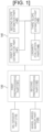
- FIG. 1 is a view illustrating an apparatus for estimating a vehicle pitch relative to a road according to an embodiment
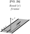
- FIGS. 2A to 2C are views for describing a coordinate system according to an embodiment
- FIG. 3 is a view for describing a vehicle pitch, a road slope, and a vehicle pitch relative to a road;
- an apparatus for estimating a vehicle pitch relative to a road may include an inertial measurement unit (IMU) sensor part 110, a wheel speed sensor part 120, a preprocessing part 130, and a slope estimation part 140.
- IMU inertial measurement unit
- the IMU sensor part 110 may obtain data about the movement of a vehicle such as an acceleration and a rotation rate, that is, IMU data.
- the acceleration may include x-, y-, and z-axis accelerations and the gravitational force on a body frame
- the rotation rate may include x-, y-, and z-axis rotation rates on the body frame.
- the body frame of FIG. 2A is a vehicle reference coordinate system which moves along with the movement of the vehicle
- a road frame of FIG. 2B is a road reference coordinate system that changes according to a road slope
- a navigation frame of FIG. 2C is a coordinate system that does not change based on a reference point regardless of the movement of the vehicle.
- Main variables using such frames may be expressed as parameter axis , time frame .
- the IMU sensor part 110 may include a gyroscope sensor and an acceleration sensor.
- the acceleration sensor may measure an acceleration and the gravitational force on the body frame. Three-axis accelerations and the gravitational force on the body frame may be measured by the IMU sensor part 110.
- the gyroscope sensor may measure a rotation rate on the body frame. Since vertical movement of the vehicle should be considered, pitch movement of the vehicle should be measured. Accordingly, a single y-axis gyroscope may be used, but the pitch movement of the vehicle may be measured even without using the single y-axis gyroscope, however, performance may be degraded.
- the speed sensor part 120 may obtain wheel speed data through a controller area network (CAN).
- CAN controller area network
- the wheel speed data may be obtained by averaging speeds of two rear wheels instead of a driving wheel but is not necessarily limited thereto.
- the preprocessing part 130 may preprocess the IMU data obtained from the IMU sensor part 110 and the wheel speed data obtained from the wheel speed sensor part 120.
- the preprocessing part 130 may include a first preprocessing part 131 and a second preprocessing part 132.
- the first preprocessing part 131 may check whether the IMU data is valid data. For example, the first preprocessing part 131 may determine that the IMU data is valid data when the IMU data is greater than or equal to a predetermined threshold and determine that the IMU data is invalid data when the IMU data is smaller than the predetermined threshold.
- the second preprocessing part 132 may extract a stop section and a moving section on the basis of the IMU data and the wheel speed data.
- the stop section is a section in which the vehicle is in a stop state and the wheel speed data indicates zero.
- the moving section may be a section in which the vehicle decelerates or accelerates.
- the first preprocessing part 131 may remove an IMU error from the IMU data.
- IMU errors There are two types of IMU errors such as bias and zero mean white noise. Such errors may cause a big problem when an acceleration and a rotation rate are integrated.
- an output of a gyroscope has only a bias and noise.
- the quality of the IMU data is improved by removing the bias of the gyroscope, and a bias is estimated through an average value to remove the zero mean white noise.
- the slope estimation part 140 may estimate a vehicle pitch relative to a road on the basis of the preprocessed IMU data and wheel speed data.
- the slope estimation part 140 may include a first slope estimation part 141, a second slope estimation part 142, a third slope estimation part 143, and a linearity evaluation part 144.
- the first slope estimation part 141 may estimate a vehicle pitch in the stop state.
- the first slope estimation part 141 may estimate a vehicle pitch in the stop section extracted by the second preprocessing part 132.
- the second slope estimation part 142 may estimate a road slope in a moving state.
- the second slope estimation part 142 may estimate the road slope in the moving section extracted by the second preprocessing part 132.
- the third slope estimation part 143 may estimate a vehicle pitch relative to a road on the basis of the estimated vehicle pitch in the stop section and the road slope in the moving section. For example, as illustrated in FIG. 3 , the third slope estimation part 143 may estimate the vehicle pitch relative to a road of ⁇ pitch road by subtracting the road slope of ⁇ road n from the vehicle pitch of ⁇ pitch n .
- the linearity evaluation part 144 may evaluate the linearity of the road in order to calculate the road slope. For example, when it is evaluated that the linearity of the road is suitable, an estimation process may be performed, and the third slope estimation part 143 may estimate the vehicle pitch relative to a road.
- FIG. 4 is a view illustrating a method of estimating a vehicle pitch relative to a road
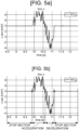
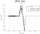
- FIGS. 5A to 5D are graphs for showing a process of extracting a road slope estimation section illustrated in FIG. 4
- FIG. 6 is a view for describing a principle of removing a bias illustrated in FIG. 4
- FIG. 7 is a view for describing a principle of estimating a vehicle pitch illustrated in FIG. 4 .
- an apparatus for estimating a vehicle pitch relative to a road may receive IMU data and wheel speed data (S110).
- the slope estimation apparatus may check whether the received IMU data is valid data (S120).
- the slope measurement apparatus may check the IMU data is valid data on the basis of predetermined parameters.
- the predetermined parameters may include an acceleration, a steering angle, and a road slope.
- the slope estimation apparatus may determine that the IMU data and the wheel speed data are invalid data and stop a slope estimation process on the basis of the IMU data and the wheel speed data when an acceleration of the vehicle is lower than or equal to a predetermined acceleration, a steering angle of the vehicle is greater than or equal to a predetermined steering angle, a road slope at which the vehicle is positioned is greater than or equal to a predetermined road slope (in a pitch direction) or a predetermined road slope (in a roll direction).
- the slope estimation apparatus may extract a road slope estimation section on the basis of the received IMU data and wheel speed data (S130).
- the road slope estimation section may include a stop-acceleration section in which the vehicle accelerates after stopping and a deceleration-stop section in which the vehicle stops after decelerating.
- IMU acceleration data of the IMU data is used.
- the slope estimation apparatus may receive the IMU acceleration data as in FIG. 5A and filter the received IMU acceleration data so as to extract IMU acceleration data having a value greater than or equal to a predetermined value.
- the slope estimation apparatus may distinguish a stop section, an acceleration section, and a deceleration section on the basis of the filtered IMU acceleration data and wheel speed data as in FIG. 5B .
- a section in which a value of an acceleration is greater than or equal to a predetermined value may be determined as a moving section that includes the acceleration section and the deceleration section.
- the slope estimation apparatus may extract the stop-acceleration section or deceleration-stop section as the road slope estimation section on the basis of the distinguished stop section, acceleration section, and deceleration section.
- a vehicle pitch relative to a road will be estimated using the IMU data and the wheel speed data in the deceleration-stop section or stop-acceleration section as described above.
- the slope estimation apparatus may remove a bias by calculating an average value of the bias in the stop section and subtracting the calculated average value of the bias from the IMU data, that is, IMU rotation rate data (S140).
- the slope estimation apparatus may estimate a static vehicle pitch, that is, a pitch and a roll, on the basis of IMU data, that is, the IMU acceleration data in the stop section (S150).
- the static vehicle pitch in the stop section is estimated on the basis of a position of the gravitational force gn, and the static vehicle pitch is defined as in Equation 1 and Equation 2.
- ⁇ pitch n atan mean acc z b stop mean acc x b stop / sin ⁇ roll n
- ⁇ roll n atan mean acc y b stop mean acc x b stop
- acc z b , acc y b , and acc x b denote z-, y-, and x-axis accelerations on the body frame.
- a pitch of a vehicle in Equation 3 is defined as a vehicle pitch.
- the slope estimation apparatus may estimate a road slope on the basis of the IMU data (S160).
- the road slope may be calculated on the basis of an acceleration, a speed, and a position, and the road slope may be defined as in Equation 3, Equation 4, and Equation 5.
- ⁇ road n 1 N ⁇ 1 N atan a z n a x n 2 + a y n 2
- a z b , a y b , and a x b denote z-, y-, and x-axis accelerations on the navigation frame.
- a z b , a y b , and a x b may be calculated by rotationally transforming acc z b , acc y b , and acc x b .
- ⁇ road n 1 N ⁇ 1 N atan v z n v x n 2 + v y n 2
- road n atan ⁇ p z n ⁇ p x n 2 + ⁇ p y n 2
- Equation 6 relationships between an acceleration, a speed, and a position are defined as in Equation 6 and Equation 7 below.
- ⁇ a x n dt v x n
- ⁇ a y n dt v y n
- ⁇ a z n dt v z n
- ⁇ z b , ⁇ y b , and ⁇ x b denote z-, y-, and x-axis speeds on the navigation frame.
- ⁇ v x n dt p x n
- ⁇ v y n dt p y n
- ⁇ v z n dt p z n
- p z b , p y b , and p x b denote z-, y-, and x-axis positions on the navigation frame.
- FIGS. 8A and 8B are views for describing a principle of calculating a road slope on the basis of a speed according to the embodiment.
- the slope estimation apparatus may receive a speed at each predetermined time in the moving section and extract a section in which the speed is greater than or equal to a predetermined speed as a region of interest on the basis of the received speed.
- the slope estimation apparatus may calculate a plurality of first road slopes on the basis of a speed of each point.
- the slope estimation apparatus may average the plurality of first road slopes to calculate one second road slope, and the second road slope is calculated as a final road slope.
- a road slope is calculated in a partial moving section instead of an entire moving section in consideration of a start margin and an end margin for a speed.
- a road slope is calculated on the basis of a speed in a remaining section excluding a partial moving section of a starting section and a partial moving section of a finishing section among an entire moving section.
- FIGS. 9A and 9B are views for describing a principle of estimating a road slope on the basis of a position according to the embodiment.
- the slope estimation apparatus receives a position at each predetermined time in the moving section and calculates a road slope on the basis of positions at a start point and an end point.
- a road slope is calculated only in a partial moving section instead of an entire moving section in consideration of a start margin and an end margin of a position.
- a road slope will be calculated on the basis of a position received in a remaining section excluding a partial moving section of a starting section and a partial moving section of a finishing section among an entire moving section.
- the start margin and the end margin may be set as a start margin ratio and an end margin ratio.
- the present invention is not necessarily limited thereto, and at least one of the start margin and the end margin may be considered.
- start margin and the end margin may have the same margin ratio, but are not necessarily limited thereto, and may have different margin ratios according to situations. For example, in a section in which the vehicle accelerates after stopping, a start margin ratio may be set to be greater than an end margin ratio, and in a section in which the vehicle stops after decelerating, an end margin ratio may be set to be greater than a start margin ratio.
- the slope estimation apparatus may evaluate the linearity of the road (S170).
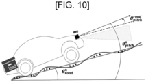
- FIG. 10 is a view for describing a principle of evaluating the linearity of the road illustrated in FIG. 4 .
- the slope estimation apparatus may fit a virtual line to a shape of a road, calculate the magnitude of an error on the basis of the virtual line and a position of the vehicle, and evaluate the linearity of the road on the basis of the calculated magnitude of the error.
- the slope estimation apparatus determines that the road is severely irregular and does not have appropriate linearity for calculating a road slope, does not estimate a vehicle pitch relative to a road, and stops an estimation process.
- the slope estimation apparatus may determine that the irregularity of the road is not severe and the linearity of the road is suitable for calculating a road slope.
- the slope estimation apparatus may estimate a vehicle pitch relative to a road on the basis of the estimated vehicle pitch and road slope (S180).
- the vehicle pitch relative to a road is defined as in Equation 8.
- ⁇ pitch road ⁇ pitch n ⁇ ⁇ road n
- a vehicle pitch relative to a road can be accurately estimated by extracting a stop section and a moving section on the basis of wheel speed data and inertial measurement unit (IMU) data, estimating a vehicle pitch in the stop section and a road slope in the moving section, and estimating a vehicle pitch relative to a road on the basis of the vehicle pitch and the road slope.
- IMU inertial measurement unit
- Unit used in the present embodiment refer to software or a hardware component such as a field-programmable gate array (FPGA) or an application-specific integrated circuit (ASIC), and objects termed “unit” perform certain roles.
- FPGA field-programmable gate array
- ASIC application-specific integrated circuit
- the term “unit” is not limited to software or hardware.
- a “unit” may be configured to reside on an addressable storage medium or to reproduce one or more processors.
- the term “unit” includes components such as software components, object-oriented software components, class components, task components, processes, functions, properties, procedures, subroutines, segments of program code, drivers, firmware, micro-code, circuits, data, data bases, data structures, tables, arrays, and variables.
- components and “units” may be combined into a smaller number of components and “units” or may be subdivided into additional components and “units.” Furthermore, the components and “units” may also be implemented to reproduce one or more central processing units (CPUs) within a device or a security multimedia card.
- CPUs central processing units
Applications Claiming Priority (1)
| Application Number | Priority Date | Filing Date | Title |
|---|---|---|---|
| KR1020220066017A KR102635242B1 (ko) | 2022-05-30 | 2022-05-30 | 도로 대비 차량의 기울기를 추정하기 위한 장치 및 그 방법 |
Publications (1)
| Publication Number | Publication Date |
|---|---|
| EP4286233A1 true EP4286233A1 (de) | 2023-12-06 |
Family
ID=84358012
Family Applications (1)
| Application Number | Title | Priority Date | Filing Date |
|---|---|---|---|
| EP22207438.7A Pending EP4286233A1 (de) | 2022-05-30 | 2022-11-15 | Vorrichtung und verfahren zur schätzung der fahrzeugneigung bezüglich der strasse |
Country Status (5)
| Country | Link |
|---|---|
| US (1) | US20230384088A1 (de) |
| EP (1) | EP4286233A1 (de) |
| JP (1) | JP2023175613A (de) |
| KR (1) | KR102635242B1 (de) |
| CN (1) | CN117141491A (de) |
Citations (3)
| Publication number | Priority date | Publication date | Assignee | Title |
|---|---|---|---|---|
| JP3375268B2 (ja) * | 1997-05-27 | 2003-02-10 | 株式会社日立製作所 | ナビゲーション装置 |
| US20170043703A1 (en) * | 2014-04-18 | 2017-02-16 | Denso Corporation | Pitch angle calculation device and optical axis adjusting device for vehicles |
| DE102016110461A1 (de) * | 2016-06-07 | 2017-12-07 | Connaught Electronics Ltd. | Verfahren zum Erkennen einer Neigung in einer Fahrbahn für ein Kraftfahrzeug, Fahrerassistenzsystem sowie Kraftfahrzeug |
Family Cites Families (2)
| Publication number | Priority date | Publication date | Assignee | Title |
|---|---|---|---|---|
| KR101909953B1 (ko) * | 2016-10-06 | 2018-12-19 | 충북대학교 산학협력단 | 라이다 센서를 이용한 차량의 자세 추정 방법 |
| KR101977749B1 (ko) * | 2017-11-21 | 2019-08-28 | 현대오트론 주식회사 | 노면 기울기를 이용한 차량 위치 추정 장치 및 그것의 위치 추정 방법 |
-
2022
- 2022-05-30 KR KR1020220066017A patent/KR102635242B1/ko active IP Right Grant
- 2022-11-15 EP EP22207438.7A patent/EP4286233A1/de active Pending
- 2022-11-18 US US18/057,174 patent/US20230384088A1/en active Pending
- 2022-11-23 CN CN202211474308.0A patent/CN117141491A/zh active Pending
- 2022-11-29 JP JP2022190777A patent/JP2023175613A/ja active Pending
Patent Citations (3)
| Publication number | Priority date | Publication date | Assignee | Title |
|---|---|---|---|---|
| JP3375268B2 (ja) * | 1997-05-27 | 2003-02-10 | 株式会社日立製作所 | ナビゲーション装置 |
| US20170043703A1 (en) * | 2014-04-18 | 2017-02-16 | Denso Corporation | Pitch angle calculation device and optical axis adjusting device for vehicles |
| DE102016110461A1 (de) * | 2016-06-07 | 2017-12-07 | Connaught Electronics Ltd. | Verfahren zum Erkennen einer Neigung in einer Fahrbahn für ein Kraftfahrzeug, Fahrerassistenzsystem sowie Kraftfahrzeug |
Also Published As
| Publication number | Publication date |
|---|---|
| US20230384088A1 (en) | 2023-11-30 |
| KR20230166272A (ko) | 2023-12-07 |
| KR102635242B1 (ko) | 2024-02-08 |
| CN117141491A (zh) | 2023-12-01 |
| JP2023175613A (ja) | 2023-12-12 |
Similar Documents
| Publication | Publication Date | Title |
|---|---|---|
| KR100387292B1 (ko) | 차량의하중이동을고려한선회반경계산방법과선회반경계산장치 | |
| US6738704B2 (en) | Apparatus and method for judging road surface gradients, and program for judging gradients | |
| US7522032B2 (en) | Method for detecting decrease in inner pressure of tire using GPS speed information | |
| US7522985B2 (en) | Method and arrangement for monitoring a measuring device located in a wheeled vehicle | |
| EP0855597B1 (de) | Vorrichtung zur Bestimmung von anfänglichen Korrekturfaktoren zur Korrektur der Drehzahlmesswerte der Reifen eines Fahrzeugs | |
| US8958940B2 (en) | Apparatus, method and program for vehicle mass estimation, and apparatus, method and program for detecting decrease in tire air pressure | |
| US8185271B2 (en) | Methods and device for determining the roll angle for occupant protection devices | |
| US7327243B2 (en) | Method for warning deflation of tires and system thereof, and judgment program of deflation of tires | |
| KR101857035B1 (ko) | 주행 정보 최적화를 통한 차량 전복 감지 시스템 | |
| JP4823642B2 (ja) | Gps情報を用いたタイヤ内圧低下警報方法および装置、ならびにタイヤ内圧低下警報プログラム | |
| US20070213904A1 (en) | Acceleration estimation device and vehicle | |
| US20110098882A1 (en) | Vehicle speed estimation device, method and device for detecting decreased tire pressure using the same | |
| JP2009510424A (ja) | 水平面に対する絶対傾斜角を求める装置 | |
| JPH11326361A (ja) | 車体のヨーレート、ロールレート、横加速度検出装置 | |
| KR19990014801A (ko) | 초기보정계수 연산장치 및 이것을 이용하는 차량용 장치 | |
| US20100131141A1 (en) | Bank angle estimation via vehicle lateral velocity with force tables | |
| CN111114551B (zh) | 一种车辆坡道坡度识别方法和装置 | |
| EP4286233A1 (de) | Vorrichtung und verfahren zur schätzung der fahrzeugneigung bezüglich der strasse | |
| ES2909575T3 (es) | Estimación de los radios de rodadura de ruedas absolutos y estimación del valor de compresión vertical | |
| EP1616725A2 (de) | Reifendruckverlustwarnsystem und Verfahren hierzu | |
| US6756891B2 (en) | Method and apparatus for detecting decrease in tire air-pressure, and selecting program for the thresholds for judging decompression of tire | |
| KR20110088095A (ko) | 뱅크 로드 검출 방법 | |
| JP3167278B2 (ja) | タイヤ空気圧低下検出方法および装置 | |
| KR20230166273A (ko) | 차량의 헤드 램프를 제어하기 위한 시스템 및 그 방법 | |
| JP2006138764A (ja) | 車輪状態監視装置および車輪状態監視方法 |
Legal Events
| Date | Code | Title | Description |
|---|---|---|---|
| PUAI | Public reference made under article 153(3) epc to a published international application that has entered the european phase |
Free format text: ORIGINAL CODE: 0009012 |
|
| STAA | Information on the status of an ep patent application or granted ep patent |
Free format text: STATUS: REQUEST FOR EXAMINATION WAS MADE |
|
| 17P | Request for examination filed |
Effective date: 20221215 |
|
| AK | Designated contracting states |
Kind code of ref document: A1 Designated state(s): AL AT BE BG CH CY CZ DE DK EE ES FI FR GB GR HR HU IE IS IT LI LT LU LV MC ME MK MT NL NO PL PT RO RS SE SI SK SM TR |