EP4286080A2 - Clamping assembly as tool holder for a tool - Google Patents
Clamping assembly as tool holder for a tool Download PDFInfo
- Publication number
- EP4286080A2 EP4286080A2 EP23198307.3A EP23198307A EP4286080A2 EP 4286080 A2 EP4286080 A2 EP 4286080A2 EP 23198307 A EP23198307 A EP 23198307A EP 4286080 A2 EP4286080 A2 EP 4286080A2
- Authority
- EP
- European Patent Office
- Prior art keywords
- peeling
- clamping
- clamping assembly
- carrier
- central axis
- Prior art date
- Legal status (The legal status is an assumption and is not a legal conclusion. Google has not performed a legal analysis and makes no representation as to the accuracy of the status listed.)
- Pending
Links
- 230000007246 mechanism Effects 0.000 claims description 82
- 239000012530 fluid Substances 0.000 claims description 58
- 238000012545 processing Methods 0.000 claims description 10
- 230000002441 reversible effect Effects 0.000 claims 1
- 238000003754 machining Methods 0.000 abstract description 4
- 230000000717 retained effect Effects 0.000 abstract description 2
- 239000000463 material Substances 0.000 description 14
- 230000036316 preload Effects 0.000 description 7
- 230000000712 assembly Effects 0.000 description 6
- 238000000429 assembly Methods 0.000 description 6
- 238000013461 design Methods 0.000 description 4
- 238000006073 displacement reaction Methods 0.000 description 4
- 239000010720 hydraulic oil Substances 0.000 description 4
- 230000006835 compression Effects 0.000 description 3
- 238000007906 compression Methods 0.000 description 3
- 238000000034 method Methods 0.000 description 3
- 238000003466 welding Methods 0.000 description 3
- 238000010438 heat treatment Methods 0.000 description 2
- 229910052751 metal Inorganic materials 0.000 description 2
- 239000002184 metal Substances 0.000 description 2
- 230000002093 peripheral effect Effects 0.000 description 2
- 229910000831 Steel Inorganic materials 0.000 description 1
- 230000006978 adaptation Effects 0.000 description 1
- 229910052782 aluminium Inorganic materials 0.000 description 1
- XAGFODPZIPBFFR-UHFFFAOYSA-N aluminium Chemical compound [Al] XAGFODPZIPBFFR-UHFFFAOYSA-N 0.000 description 1
- 238000013459 approach Methods 0.000 description 1
- 238000004891 communication Methods 0.000 description 1
- 238000011109 contamination Methods 0.000 description 1
- 230000007547 defect Effects 0.000 description 1
- 230000001419 dependent effect Effects 0.000 description 1
- 238000011161 development Methods 0.000 description 1
- 230000018109 developmental process Effects 0.000 description 1
- 239000007789 gas Substances 0.000 description 1
- 230000001771 impaired effect Effects 0.000 description 1
- 230000010354 integration Effects 0.000 description 1
- 230000003647 oxidation Effects 0.000 description 1
- 238000007254 oxidation reaction Methods 0.000 description 1
- 230000000149 penetrating effect Effects 0.000 description 1
- 230000035515 penetration Effects 0.000 description 1
- 230000002040 relaxant effect Effects 0.000 description 1
- 238000007790 scraping Methods 0.000 description 1
- 239000007787 solid Substances 0.000 description 1
- 239000010959 steel Substances 0.000 description 1
- 239000000126 substance Substances 0.000 description 1
- 238000009423 ventilation Methods 0.000 description 1
- XLYOFNOQVPJJNP-UHFFFAOYSA-N water Substances O XLYOFNOQVPJJNP-UHFFFAOYSA-N 0.000 description 1
Images


Classifications
-
- B—PERFORMING OPERATIONS; TRANSPORTING
- B26—HAND CUTTING TOOLS; CUTTING; SEVERING
- B26D—CUTTING; DETAILS COMMON TO MACHINES FOR PERFORATING, PUNCHING, CUTTING-OUT, STAMPING-OUT OR SEVERING
- B26D3/00—Cutting work characterised by the nature of the cut made; Apparatus therefor
- B26D3/16—Cutting rods or tubes transversely
- B26D3/164—Cutting rods or tubes transversely characterised by means for supporting the tube from the inside
-
- B—PERFORMING OPERATIONS; TRANSPORTING
- B23—MACHINE TOOLS; METAL-WORKING NOT OTHERWISE PROVIDED FOR
- B23B—TURNING; BORING
- B23B5/00—Turning-machines or devices specially adapted for particular work; Accessories specially adapted therefor
- B23B5/16—Turning-machines or devices specially adapted for particular work; Accessories specially adapted therefor for bevelling, chamfering, or deburring the ends of bars or tubes
- B23B5/161—Devices attached to the workpiece
- B23B5/162—Devices attached to the workpiece with an internal clamping device
-
- B—PERFORMING OPERATIONS; TRANSPORTING
- B23—MACHINE TOOLS; METAL-WORKING NOT OTHERWISE PROVIDED FOR
- B23B—TURNING; BORING
- B23B2220/00—Details of turning, boring or drilling processes
- B23B2220/40—Peeling
-
- B—PERFORMING OPERATIONS; TRANSPORTING
- B23—MACHINE TOOLS; METAL-WORKING NOT OTHERWISE PROVIDED FOR
- B23B—TURNING; BORING
- B23B2260/00—Details of constructional elements
- B23B2260/03—Clamps
-
- B—PERFORMING OPERATIONS; TRANSPORTING
- B23—MACHINE TOOLS; METAL-WORKING NOT OTHERWISE PROVIDED FOR
- B23B—TURNING; BORING
- B23B2270/00—Details of turning, boring or drilling machines, processes or tools not otherwise provided for
- B23B2270/02—Use of a particular power source
- B23B2270/025—Hydraulics
-
- B—PERFORMING OPERATIONS; TRANSPORTING
- B23—MACHINE TOOLS; METAL-WORKING NOT OTHERWISE PROVIDED FOR
- B23B—TURNING; BORING
- B23B2270/00—Details of turning, boring or drilling machines, processes or tools not otherwise provided for
- B23B2270/08—Clamping mechanisms; Provisions for clamping
Definitions
- the present invention relates to a peeling device for at least partially removing the surface of an at least approximately tubular body and to a clamping assembly as a tool carrier for a tool, such as a peeling knife arrangement of a peeling device, for processing an approximately tubular body.
- the present invention relates to a peeling device for at least partially removing the surface of an at least approximately tubular body with a central axis, in particular a plastic pipe, with a clamping assembly having a central axis and at least one clamping element for clamping the peeling device on the tubular body, wherein in the assembled state, the central axis of the clamping assembly coincides at least approximately with the central axis of the tubular body, and with a peeling assembly comprising a peeling arm unit, a peeling knife arrangement arranged at a first end of the peeling arm unit and a peeling arm carrier which connects the clamping assembly to the peeling arm unit, the peeling arm unit having a second end is connected to the peeling arm carrier in such a way that the peeling arm unit and the central axis of the clamping assembly lie in a common plane, the peeling knife arrangement having a peeling knife.
- the present invention further relates to a clamping assembly as a tool carrier for a tool, such as a peeling knife arrangement of a peeling device, for processing an approximately tubular body with a central axis, in particular a plastic tube.
- the clamping assembly has a central axis, a carrier shaft arranged coaxially to the central axis of the clamping assembly and at least one clamping device arranged on the carrier shaft and directed essentially radially outwards.
- plastic pipes for this purpose.
- the plastic pipes are connected at their ends to one another or to other shaped parts, such as T-pieces or cross pieces, for example via heating coil fittings by means of heating coil welding.
- the outer surfaces of the plastic pipes are slightly removed before the actual welding in those places where welding with a molded part or the like is to take place.
- plastic pipes or their ends are not always exactly cylindrical, but can have ovalities.
- the surface of such plastic pipes can have further unevenness, such as scratches or grooves, or chemical changes, such as oxidation or contamination, which can prevent a secure and/or media-tight connection between the tubular body and the fitting placed on it, or at least the quality of this affect connection. It is therefore customary to process the sections of the tubular body on which such a shaped piece is to be placed using a peeling device in order to eliminate such unevenness or changes in the tubular body surface.
- a peeling device for scraping the outer surface of a plastic pipe which is clamped by means of clamping arms in one end of the plastic pipe or tubular body to be processed.
- An arm which carries a scraper blade at its free end, is aligned parallel to the surface of the tubular body so that the scraper blade rests on the tubular body.
- the other end of the arm is connected to a drive spindle so that the arm can be driven to rotate around the tubular body, with the scraper blade removing material from the surface of the tubular body.
- peeling devices for removing material from the surface of a plastic pipe are essentially C-shaped and have a scraper blade directed towards the inside.
- a peeling device is from the EP patent application 1 160 035 known.
- the scraper blade In addition to the scraper blade, it has rollers on its inside, by means of which the peeling device can roll along the surface of the tubular body to be processed, while the scraper blade removes material from the pipe surface.
- a peeling device for at least partially removing the surface of an at least approximately tubular body with a central axis, in particular a plastic pipe, with a clamping assembly having a central axis and at least one clamping element for clamping the peeling device on the tubular body, the central axis in the assembled state the clamping assembly at least approximately coincides with the central axis of the tubular body, and with a peeling assembly comprising a peeling arm unit, a peeling knife arrangement arranged at a first end of the peeling arm unit and a peeling arm carrier with a first end and a second end which connects the clamping assembly to the peeling arm unit, wherein the peeling arm unit is connected at a second end to the peeling arm carrier in such a way that the peeling arm unit and the central axis of the clamping assembly lie in a common plane in the assembled state.
- the peeling knife arrangement has a peeling knife which is arranged at a first end of the peeling arm unit.
- the peeling arm unit is connected with its first and second ends to the peeling knife arrangement and the peeling arm carrier and can be pivoted in the common plane with the central axis of the clamping assembly so that the knife carriage maintains its alignment with the central axis of the clamping assembly in every pivoting position of the peeling arm unit .
- This can ensure that a paring knife of a paring knife arrangement maintains its alignment with the tubular body to be machined at every processing time, whereby uniform material removal and a high surface quality can be guaranteed.
- the paring knife arrangement can be designed in different ways.
- the peeling knife arrangement has a knife carriage with a peeling knife arranged therein or on it, which is arranged at the end of the peeling arm unit. Such a knife carriage can ensure precise guidance of the paring knife.
- the pivot axes can be implemented in different ways. In one embodiment it can be provided that the pivot axes are formed by hinge pins which are accommodated in corresponding bores.
- the peeling arm unit has at least mutually parallel first and second peeling arm elements with first and second ends, which are pivotally connected to the peeling knife arrangement and the peeling arm carrier, with oriented perpendicular to the common plane of the peeling arm unit and the central axis of the clamping assembly Swivel axes.
- This configuration enables the peeling knife arrangement or the knife carriage to compensate for ovalities of the tubular body to be processed and at the same time to adapt to the reduced or reducing diameter of the processed tubular body.
- the alignment of the paring knife arrangement or the knife carriage, and thus the alignment of the paring knife, to the tubular body axis is retained.
- the peeling arm elements are arranged one above the other in the radial direction, relative to the central axis of the clamping assembly, whereby your movement of the knife carriage exclusively in the common direction Level of the peeling arm unit and the central axis of the clamping assembly can be ensured.
- the distances between the pivot axes in the radial direction, relative to the central axis of the clamping assembly, and in the axial direction, relative to the central axis of the clamping assembly are the same size, so that the pivot axes are in the common plane of the peeling arm unit and the central axis of the clamping assembly form the corner points of a parallelogram. This achieves the desired movement of the paring knife arrangement relative to the tubular body.
- the distances between the pivot axes are the same size in the radial direction, relative to the central axis of the clamping assembly, but are different in the axial direction, relative to the central axis of the clamping assembly.
- a desired movement of the peeling knife arrangement relative to the tubular body can thereby be achieved.
- At least one of the bores attached to one of the second ends of the peeling arm elements for receiving the hinge pins forming the pivot axes has a larger cross section that deviates from the cross section of the hinge pin. This achieves additional pivotability of the peeling knife arrangement in order to further improve the alignment of the peeling knife with respect to the tubular body to be processed.
- the cross section of the hole receiving the hinge pin can, for example, have the shape of an elongated hole, or be a hole with a larger diameter than the diameter of the hinge pin.
- the cross section of the bore can also have any other shape, as long as this allows additional pivoting of the peeling knife arrangement to be achieved.
- the elongated hole can be designed differently.
- the elongated hole is designed in the shape of an arc or part of a circle.
- the diameter of one of the bores is larger than the diameter of the hinge pin accommodated therein.
- the tilt angle that can be achieved through this additional tiltability of the peeling knife arrangement can be between 0.5° to 20°, preferably 2.5° to 12.5°, more preferably 3° and 7°, particularly preferably approximately 5°.
- a support element is arranged between the second ends of the peeling arm elements and the peeling knife arrangement.
- a carrier element enables a targeted alignment of the peeling knife arrangement to the peeling arm elements.
- the peeling knife arrangement includes the peeling knife and the associated fastening elements and, if necessary, alignment elements, which are arranged directly on the carrier element. If the peeling knife arrangement includes a knife carriage, this is attached to the support element.
- the second ends of the first and second peeling arm elements are at least approximately C-shaped and at least partially surround the carrier element. This configuration enables the hinge pins to be attached in the area of the C-shaped ends, which, in addition to the desired pivotability, also enables the peeling arm elements to be guided in the pivoting plane.
- first end of the first peeling arm element is at least approximately C-shaped and at least partially surrounds the peeling arm carrier in order to ensure guidance in the pivoting plane of the peeling arm unit here too.
- the first end of the second peeling arm element can have an opening into which the peeling arm carrier projects with its first end. This ensures the pivotability and guidance of the second peeling arm element in its pivoting plane.
- the carrier element is arranged laterally next to the second ends of the first and second peeling arm elements.
- first and second peeling arm elements For the pivotable arrangement of the first and second peeling arm elements on the peeling arm carrier, it is also possible for the first ends of the first and second peeling arm elements to be received in a recess at the second end of the peeling arm carrier and to be pivotably held in this by means of the hinge bolts.
- the peeling device comprises a force application unit which exerts a deflection force on the peeling arm unit for reversibly prestressing the peeling arm unit in a peeling position, in a direction in the common plane of the peeling arm unit and the central axis of the clamping assembly.
- the knife carriage is always in contact with the pipe surface.
- the peeling knife is prevented from lifting off the pipe surface, so that material can be removed, for example to reduce or eliminate scratches or grooves in the pipe surface.
- the paring knife can be pretensioned in different ways.
- the force application unit has at least one elastic element, such as a spring, for generating the deflection force.
- An elastic element represents a technically simple way to generate a preload.
- the force application unit has an adjustment mechanism for adjusting the level of the deflection force. By adjusting the level of the deflection force, it can be ensured that the knife carriage sits on the pipe surface even with larger ovalities of the tubular body.
- the adjustment mechanism can be operated in different ways.
- the adjustment mechanism comprises a tensioning lever.
- other actuating elements can also be used, such as adjusting screws or the like.
- the clamping lever has an eccentric cam and can be pivoted about an axis of rotation in such a way that the elastic element is compressed, whereby the deflection force is generated, or is relieved.
- the adjustment mechanism has a pressure plate which can be reversibly displaced along the peeling arm support, the elastic element being arranged between the pressure plate and a section of the peeling arm unit. By moving the pressure plate relative to the section of the peeling arm unit, the elastic element located therebetween can be put under tension in order to set a desired preload with which the knife carriage rests on the pipe surface.
- the pressure plate can be moved directly by hand by the operator along the peeling arm carrier. This preferably happens when the peeling arm unit is in an unloaded state. The pressure plate is adjusted and clamped in a powerless state. By then aligning the peeling arm unit into the peeling position, the pretension can be set to the desired value or, if necessary, increased further.
- a lever with an eccentric mechanism such as the tensioning lever with its eccentric cam, can be provided in order to put the elastic element under tension.
- the eccentric mechanism can be designed in such a way that when pivoting about the axis of rotation it acts on the pressure plate, which can be reversibly displaced along the peeling arm carrier.
- the adjusting mechanism for adjusting the level of the deflection force comprises an adjusting screw mechanism.
- This can include a hand-operated adjusting screw, which further simplifies the operation of the adjustment mechanism.
- a stopper or stop which limits the deflection of the peeling arm unit.
- an elastic element can also be provided, which is compressed into a state predetermined by the stop, which results in a fixed value of a deflection force.
- a stop can be realized in the form of a screw, which is arranged so that the peeling arm unit or an element thereof comes into contact with the screw head.
- Other elements such as a pin or a bolt, are also suitable as a stop.
- peeling knife arranged in the knife carriage is also biased in a direction perpendicular to the central axis of the clamping assembly, this can ensure uniform material removal.
- the knife carriage has at least two rollers arranged at least approximately axially parallel to the central axis of the clamping assembly, which rest on the surface of the tubular body in the assembled state of the peeling device.
- the rollers or wheels not only enable the knife carriage to be guided smoothly and evenly over the pipe surface, but also keep the knife carriage at a constant distance from the pipe surface.
- the distance of the peeling arm unit to the central axis of the clamping assembly is adjustable.
- the distance between the peeling arm unit and the central axis of the clamping assembly can be adjusted in different ways.
- An embodiment is preferred in which the peeling arm carrier can be displaced along the clamping assembly and at least approximately perpendicular to its central axis.
- the peeling arm unit is designed to be displaceable along the peeling arm carrier and to be correspondingly fixable to it in the different positions.
- the position of the peeling arm carrier is adjustable along the central axis of the clamping assembly. This allows the pipe surface to be processed in the axial direction to a desired length without releasing the tension of the peeling device on the tubular body.
- the position of the peeling arm carrier along the central axis of the clamping assembly can be changed step by step, for example after each revolution of the peeling arm unit around the tubular body, or continuously.
- An adjustment mechanism provided for this purpose can include, for example, a clamping device for the peeling arm carrier on the central axis of the clamping assembly, or a spindle mechanism by means of which the peeling arm carrier, and thus the peeling assembly, is displaced a certain distance along the central axis of the clamping device with each revolution around the tubular body .
- the clamping assembly may comprise only one clamping element. But in order to secure the peeling device in a precise position, preferably coaxially, it is provided that the clamping assembly has more than one clamping element, preferably three clamping elements, preferably in the form of clamping scissors.
- the clamping elements are arranged at the same angular pitch to one another in order to support central attachment of the clamping assembly in the tubular body. If three clamping elements are provided, they are arranged at an angle of 120° to one another.
- a holding element is arranged in the immediate vicinity of the central axis of the clamping assembly and between two adjacent clamping elements.
- a holding element can, for example, be designed as a handle in the form of a metal rod, or be formed by a suitable webbing or a belt loop, whereby the holding element should be attached to the tensioning assembly in such a way that the function of the tensioning assemblies is not impaired.
- a clamping assembly is proposed as a tool carrier for a tool, such as a peeling knife arrangement of a peeling device, for processing an approximately tubular body with a central axis, in particular a plastic tube.
- the tool carrier or the clamping assembly has a central axis, a carrier shaft arranged coaxially to the central axis of the clamping assembly and at least one clamping device arranged on the carrier shaft and directed essentially radially outwards.
- an actuation mechanism for actuating the at least one clamping device is arranged on the carrier shaft, for reversibly clamping the clamping assembly in the tubular body coaxially to its central axis. This enables a compact design and easy operation of the tool carrier or clamping assembly.
- the clamping assembly according to the invention is suitable as a tool carrier for different types of tools intended for machining a tubular body or the like Tools that are placed in a specific orientation to the tubular body.
- the clamping assembly according to the invention can be arranged coaxially to the central axis of the tubular body to be machined, and preferably in this. This is particularly advantageous if an at least approximately circular movement is to be carried out with respect to the central axis of the tubular body, such as a peeling tool, a pipe cutter, a thread cutter or the like.
- the at least one clamping device comprises at least one clamping scissor with at least two scissor elements that are articulated to one another, as well as at least one clamping element displaceably arranged on the support shaft, with which one of the at least two scissor elements of the at least one clamping scissors is articulated, and for actuating the clamping device by the Actuating mechanism is reversibly displaceable on the carrier shaft.
- the carrier wave can be designed differently. It can be provided as a solid shaft or as a hollow shaft. If the carrier shaft is designed as a hollow shaft, it is possible, for example, to guide a spindle, such as a threaded spindle, through this hollow shaft, to which the machining tool can be attached and held rotatable about the central axis of the clamping assembly.
- a spindle such as a threaded spindle
- the actuating mechanism comprises a threaded connection or threaded engagement between the carrier shaft and the at least one clamping element and an actuating element. It can be provided that the carrier shaft has an external thread that interacts with an internal thread of the at least one clamping element.
- the actuating element can be designed in the form of a nut or a lever, so that the actuating mechanism can be operated in a simple manner, for example with a wrench or by hand.
- a motor drive for this actuation mechanism is also conceivable.
- the actuating mechanism can comprise at least one piston-cylinder mechanism arranged coaxially on the carrier shaft, which cooperates with the at least one clamping element. This further simplifies the operation of the actuation mechanism.
- an annular cylinder space is formed between the carrier shaft and a cylinder sleeve arranged coaxially on the carrier shaft and in which an annular piston is arranged.
- the cylinder sleeve is reversibly displaceable on the carrier shaft by the actuation mechanism.
- the at least one clamping element is connected to the cylinder sleeve and is reversibly displaced on the carrier shaft by this.
- the cylinder sleeve firmly on the carrier shaft, so that the annular piston can be displaced in the annular cylinder space.
- the annular piston is connected to the at least one clamping element in order to displace it on the carrier shaft.
- the at least one piston-cylinder mechanism is connected to an external fluid source.
- a fluid source can be a hydraulic or pneumatic pump that pumps a corresponding fluid, such as hydraulic oil or air, into the piston-cylinder mechanism.
- the clamping assembly has a second clamping element which is displaceably arranged on the support shaft and which is articulated to the second of the at least two scissor elements of the clamping scissors, and a further piston-cylinder connected to the second clamping element mechanism includes.
- This further piston-cylinder mechanism preferably corresponds in structure to the first piston-cylinder mechanism and can be connected to the same fluid source. It is also possible to control both piston-cylinder mechanisms separately or to control the piston-cylinder mechanisms synchronously.
- the actuation mechanism has an integrated drive mechanism, whereby a particularly compact structure and further simplified operation of the clamping assembly is achieved.
- the integrated drive mechanism can also have an integrated fluid reservoir for receiving a fluid, such as hydraulic oil. This makes the clamping assembly independent of an external fluid source or a fluid supply.
- the fluid reservoir can be implemented in different ways. In the simplest case it is a corresponding container that can be attached to the carrier shaft, for example.
- the clamping assembly can be provided with a further cylinder sleeve arranged coaxially on the cylinder sleeve to form an integrated fluid reservoir between the cylinder sleeve and the further cylinder sleeve.
- the further cylinder sleeve for forming the fluid reservoir can be provided as a separate element.
- it is provided that it has a connection element arranged coaxially on the carrier shaft, which, in addition to other elements, also includes the further cylinder sleeve. This achieves a high degree of integration and reliable operation of the clamping assembly according to the invention.
- the clamping assembly can include an integrated pump mechanism for transferring the fluid from the fluid reservoir into the cylinder space of the piston-cylinder mechanism with a pump cylinder integrated in the further cylinder sleeve and a pump piston guided therein.
- the drive of the integrated pump mechanism can be designed differently, for example in the form of an electric drive.
- the integrated pump mechanism includes a lever for manually operating the pump mechanism.
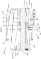
- Fig. 1 shows a schematic perspective view of a first exemplary embodiment of a peeling device S according to the present invention.
- the peeling device S in the following version Fig. 1 comprises a clamping assembly 10 with a central axis MS, a peeling assembly 20 with a peeling arm unit 30, a peeling knife arrangement 40, a force application unit 50, and a peeling arm carrier 60.
- the peeling device S is attached to a tubular body R, the surface material of which is at least partially different from the in Fig. 1 must be peeled off or removed from the front side that can be seen.
- the clamping assembly 10 used to fix the peeling assembly 20 on the tubular body R comprises a carrier shaft in the form of a hollow shaft or carrier sleeve 12, a shaft in the form of an in Fig. 1 horizontally aligned threaded spindle 16, on which the carrier sleeve 12 is arranged, and which extends coaxially to the central axis MS of the clamping assembly 10.
- the carrier sleeve 12 points at its in Fig. 1 left end has a first flange 13 which extends radially outwards from the carrier sleeve 12.
- the clamping scissors 14 each comprise two scissor elements 14a, 14b that are articulated to one another, with one end of the scissor elements 14a being articulated to the carrier sleeve 12 via the first flange 13, and the scissor elements 14b having their corresponding ends connected to one another second flange 13 (cf. Fig. 6 ) or a comparable element are articulated.
- This second flange 13 is preferably arranged on the carrier sleeve 12 so that it can be moved at least axially.
- the clamping scissors 14 By moving the second flange 13 relative to the first flange 13 on the carrier sleeve 12, the clamping scissors 14 lengthen or shorten, as described in connection with Fig. 6 is explained. As a result, the clamping assembly 10 inserted into the tubular body R can be clamped in the tubular body R or released from it and removed in a manner known per se.
- the central axis of the support sleeve 12 is aligned coaxially with the central axis MR of the tubular body or the tube R.
- FIG. 1 Support or retaining strap, not shown, which is attached between the two flanges 13, can facilitate the handling of the clamping assembly 10 when clamping it into the tubular body R. It enables precise positioning of the clamping assembly 10 in the tubular body R, and reduces the risk of crushing during the clamping and releasing process.
- the first flange 13 is axially fixed, but is held rotatably on the carrier sleeve 12 about the central axis MS of the clamping assembly 10.
- An on in Fig. 1 Clamping element in the form of a nut 18 attached to the left end of the carrier sleeve 12 is firmly connected to the carrier sleeve 12.
- the in Fig. 1 Invisible second flange 13 is attached to the right end of the carrier sleeve 12 in an axially displaceable manner.
- the support sleeve 12 has an external thread 12a in the area of its right end, onto which the second flange 13 can be screwed using a corresponding internal thread.
- the carrier sleeve 12 By turning the nut 18, the carrier sleeve 12 also rotates about its central axis or the central axis MS of the clamping assembly 10.
- the second flange 13 moves reversibly in the axial direction along the carrier sleeve 12 towards the first flange 13, with the clamping scissors 14 opposing the inner pipe wall can be tightened or released from it (cf. Fig. 6 ).
- the peeling arm carrier 60 is attached to the left end 16a of the threaded spindle 16.
- the peeling arm carrier 60 is essentially rod-shaped and has an approximately square cross-sectional profile in the exemplary embodiments shown. One pointing the way from the threaded spindle 16 in the assembled state
- the elongated hole 66 provided on the side of the peeling arm carrier 60 extends from an area on which in Fig. 1 lower first end 62 of the peeling arm carrier 60 in the direction of the second end 64 approximately up to its middle, and perpendicular to the longitudinal extent of the peeling arm carrier 60 through it.
- the peeling arm carrier 60 is releasably attached to the left end 16a of the threaded spindle 16 by means of a fastening element 68 inserted through the elongated hole 66, such as a screw.
- the peeling arm carrier 60 is aligned perpendicular to the threaded spindle 16, that is, it is in Fig. 1 vertically aligned.
- the peeling arm carrier 60 is formed by a hollow profile, there can be a fastening element in its interior, such as a sliding nut, a sliding block or the like, by means of which the peeling arm carrier 60 can be fastened to the threaded spindle 16.
- the threaded spindle 16 can extend through the elongated hole 66.
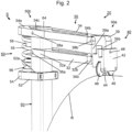
- Fig. 2 shows an enlarged perspective view.
- the peeling assembly 20 includes the peeling arm unit 30, the peeling knife arrangement 40 and the force application unit 50.
- the peeling arm unit 30 has two parallel and spaced apart from each other and in Fig. 1 horizontally aligned first and second peeling arm elements 32, 34 each having first and second ends 32a, 34a; 32b, 34b.
- the peeling arm elements 32, 34 lie in the common plane of the peeling arm unit 30 and the central axis MS of the clamping assembly 10, that is, they are arranged one above the other in the radial direction in relation to the central axis MS of the clamping assembly 10.
- the first ends 32a, 34a of the peeling arm elements 32, 34 are held in an articulated manner in the area of the second end 64 of the peeling arm carrier 60 via hinge bolts 36a, 38a.
- the hinge pins 36a, 38a are aligned transversely to the longitudinal extent of the peeling arm carrier 60 and perpendicular to the central axis MS of the clamping assembly 10.
- the peeling arm elements 32, 34 have a substantially rectangular cross section, in an area between their first and second ends 32a, 34a; 32b, 34b extending recesses which reduce the weight of the peeling arm elements 32, 34.
- the peeling arm elements 32, 34 can also have any other suitable cross section, such as a round, oval or triangular cross section.
- the second ends 32b, 34b of the peeling arm elements 32, 34 are articulated via hinge bolts 36b, 38b to a first leg 39a of a substantially C-shaped support element 39.
- the C-shaped support element 39 is aligned so that the letter "C” it forms on the head with reference to Fig. 2 , downward-pointing free legs 39a, 39b.
- the hinge pins 36b, 38b are also aligned transversely to the longitudinal extent of the peeling arm carrier 60 and perpendicular to the central axis MS of the clamping assembly 10.
- the respective radial relative to the central axis MS of the clamping assembly 10, ie the corresponding one Figures 1 to 5 vertical distance between the hinge pins 36a, 38a and the hinge pins 36b, 38b is identical. Furthermore, the distances between the hinge pins 36a, 36b of the peeling arm element 32 and between the hinge pins 38a, 38b of the peeling arm element 34 in the axial direction are also related to the central axis MS of the clamping assembly 10, ie the corresponding Figures 1 to 5 in the horizontal direction, the same size, so that between the hinge pins 36a, 36b; 38a, 38b lying sections of the peeling arm elements 32, 34 with the corresponding sections of the peeling arm carrier 60 and the leg 39a of the carrier element 39 facing them form a parallelogram, in the corner points of which the hinge pins 36a, 36b; 38a, 38b lie.
- the alignment of the peeling knife arrangement 40 to the peeling arm carrier 60, and thus also the orientation of the peeling knife arrangement 40 to the tubular body R, remains the same in every pivoting position of the peeling arm unit 30 in the circumferential direction of the tubular body R.
- the pairs of hinge pins 36a, 38a; 36b, 38b each aligned radially to the central axis MS of the clamping assembly 10
- Line arranged accordingly Fig. 2 is aligned perpendicular to the horizontally extending central axis MS of the clamping assembly 10.
- a deviation from this vertical alignment is possible, at least within limits.
- the paring knife arrangement 40 is attached to the second leg 39b of the essentially C-shaped support element 39.
- the paring knife arrangement 40 has a substantially cuboid knife carriage 42, in which a paring knife 44 is arranged such that it protrudes or protrudes from the knife carriage 42 on the side facing the central axis MS of the clamping assembly 10.
- the knife carriage 42 also has two rollers or wheels 46 arranged one behind the other in relation to the circumferential direction of the tubular body R, the axes of which are aligned parallel to one another and parallel to the central axis MS of the clamping assembly 10 when attached to a tubular body R.
- the rollers 46 protrude from the side of the knife carriage 42 facing the central axis MS of the clamping assembly 10.
- the rollers 46 When attached to a tubular body R, the rollers 46 stand on the surface of the tubular body R, so that the knife carriage 42 can roll on the tubular body R.
- the paring knife 44 which protrudes from the knife carriage 42 in the direction of the tubular body R, is biased in the direction of the central axis MR of the tubular body R by a spring element, not shown, so that it rests on the tubular body R under this bias and into the material can penetrate on the outer peripheral surface of the tubular body R.
- the knife carriage 42 is connected to the second leg 39b of the carrier element 39 via a hinge pin 48 and can be pivoted about the carrier element 39.
- the hinge pin 48 is aligned parallel to the central axis MS of the clamping assembly 10. This means that the knife carriage 42 can possibly Surface defects, such as flattenings, present on the surface of the tubular body R follow or compensate for them without departing from it.
- the first end 32a of the first peeling arm element 32 facing the peeling arm carrier 60 is C-shaped and thus partially surrounds the peeling arm carrier 60.
- the first end 34a of the second peeling arm element 34 has an opening 34c, the cross section of which at least approximately corresponds to the cross section of the peeling arm carrier 60, which extends or engages into this opening 34c, but can also pass through it completely.
- the first peeling arm element 32 ends with its first end 32a on the peeling arm carrier 60, whereas the second peeling arm element 34 ends with its first end 34a over the peeling arm carrier 60 in Fig. 2 protrudes to the left.
- a pressure plate 52 is arranged on the peeling arm carrier 60, which is shown in the illustration Figures 1 and 2 is at least approximately horizontally aligned.
- the pressure plate 52 has an opening 52a, the cross section of which essentially corresponds to the cross section of the peeling arm carrier 60, which extends at least approximately vertically through this opening 52a.
- the opening 52a is slightly larger than the cross section of the peeling arm carrier 60, so that the pressure plate 52 can be moved along the peeling arm carrier 60.
- the opening 52a is arranged in the section of the pressure plate 52 facing the peeling knife arrangement 40, so that the pressure plate 52 extends essentially to the side of the peeling arm carrier 60 opposite the peeling knife arrangement 40, and here forms a pressure plate section 54.
- An elastic element 58 forming a force-applying element is arranged between the first end 34a of the peeling arm element 34 and the pressure plate section 54 of the pressure plate 52.
- Essentially cylindrical guide or securing elements 56 are attached to the mutually facing surfaces of the first end 34a of the peeling arm element 34 and the pressure plate section 54 of the pressure plate 52, which secure the elastic element 54 in its position.
- the opening 52a in the pressure plate 52 is designed in such a way that the pressure plate 52 is tilted in a desired position on the peeling arm carrier 60 under the influence of a force applied by the elastic element 54 and is thus secured in this position against further displacement.
- the pressure plate 52 can additionally be provided with at least one securing element in order to fix it in the desired position and to secure it against unintentional displacement, for example in the event of possible load changes.
- screws can be provided in the pressure plate 52 as securing elements, by means of which it can be clamped on the peeling arm carrier 60 in the desired position. It is also conceivable to attach a clamping element to the peeling arm carrier 60 directly below the pressure plate 52 when it is in the desired position.
- the pressure plate 52 with the pressure plate section 54, the guide or securing elements 56 and the elastic element 54 form the force application unit or pretensioning device 50. This generates a deflection force or preload acting on the peeling arm unit 30, with which the peeling knife arrangement 40 with the rollers 46 on the tubular body R rests.
- FIG. 3 to 5 shown second embodiment of the peeling device S according to the invention also includes a clamping assembly 10 and a peeling assembly 20 with a peeling arm unit 30, a peeling knife arrangement 40 and a peeling arm carrier 60, which are identical to the corresponding assemblies of the peeling device S according to Figures 1 and 2 are constructed and designed.
- the second embodiment of the Figures 3 to 5 differs from the first exemplary embodiment accordingly Figures 1 and 2 in the structure of the force application unit 70.
- the force application unit 70 of the peeling device S In addition to a pressure plate 72, which has the same structure as the pressure plate 52 and has a corresponding pressure plate section 74, it also includes an elastic element 78, which is arranged between the pressure plate section 74 and the first end 34a of the peeling arm element 34 and through corresponding guide or securing elements 76 is secured in its position.
- the tensioning lever arrangement 80 comprises a tubular sleeve 82, the cross section of which essentially corresponds to the cross section of the peeling arm carrier 60, but is slightly larger than this, and which is displaceably arranged on the peeling arm carrier 60.
- the sleeve 82 can be detachably connected to the peeling arm carrier 60, for example by means of appropriate locking screws or another suitable clamping device, in order to secure it in its position on the peeling arm carrier 60.
- a clamping lever 84 with a first end 84a and a second end 84b is attached to the sleeve 82 so that it can pivot about an axis of rotation 86 arranged in the area of the second end 84b.
- the axis of rotation 86 extends essentially perpendicular to the longitudinal extent of the peeling arm carrier 60 and transversely to the central axis MS of the clamping assembly 10.
- the axis of rotation 86 can extend through the peeling arm carrier 60 and the sleeve 82 in order to fix the sleeve 82 on the peeling arm carrier 60.
- the tensioning lever 84 has an eccentric cam 88 in the area of its second end 84b. This is designed in such a way that the distance between the axis 86 and the long side edge of the clamping lever 84 on the long side of the clamping lever 84 is smaller than the distance between the axis of rotation 86 and the front end of the clamping lever 84.
- the pressure plate 72 is in the pre-stressed state of the peeling assembly 20, like this one in Fig. 4 is shown, compared to the unbiased state shown in Fig. 3 can be seen, towards the second end 64 of the peeling arm carrier 60 is displaced, whereby the elastic element 78 is compressed.
- the eccentric cam 88 can be designed such that the clamping lever 84 is secured against unintentional actuation in the pre-stressed state of the peeling assembly 20 in this clamping position.
- a correspondingly designed end face of the clamping lever 84 can be provided in the area of the eccentric cam 88, which can have a flattening or a locking element which interacts with the corresponding surface of the pressure plate 72.
- the tensioning lever 84 is designed accordingly Figures 3 to 5 formed by two identical partial levers which are arranged on two opposite sides of the sleeve 82.
- the partial levers it is possible for the partial levers to be connected to one another not only via the axis of rotation 86, but also at their free ends, so that, for example, the sections pointing away from the axis of rotation 86 form a common U-shaped section, which in the prestressed state the peeling assembly 20 accordingly Fig. 4 , which encompasses the peeling arm carrier 60.
- Fig. 6 shows a schematic, perspective view of a third exemplary embodiment of a peeling device according to the present invention, but without an associated clamping assembly, such as the clamping assembly 10.
- an associated clamping assembly such as the clamping assembly 10.
- this peeling device includes a peeling assembly 120 and a force application unit 150, which are arranged at the upper, second end 164 of the peeling arm carrier 160.
- the peeling arm carrier 160 essentially has a cuboid shape and includes an elongated hole 166 which extends at least approximately parallel to the longitudinal extent of the peeling arm carrier 160 and which extends from its first End 162 extends in the direction of its second end 164 and perpendicular to the longitudinal extent of the peeling arm carrier 160 through it.
- the peeling arm carrier 160 can be attached to a clamping assembly, such as the clamping assembly 10, by means of the elongated hole 166, as explained in connection with the first and second exemplary embodiments of the peeling device S.
- the peeling arm carrier 160 is, as also in Fig.
- a U-shaped recess 167 which extends at least approximately perpendicular to the longitudinal axis of the peeling arm carrier 160 over the entire width of the carrier 160, extends from the end face of the peeling arm carrier 166 in the direction of the first end 162.
- the depth of the recess 167 corresponds to approximately the height of the peeling arm unit 130, and the width of the recess 167 corresponds approximately to the width of the peeling arm unit 130.
- the peeling assembly 120 includes the peeling arm unit 130 and the peeling knife arrangement 140.
- the peeling arm unit 130 has two parallel and spaced-apart first and second peeling arm elements 134, 132, each with first and second ends 132a, 134a; 132b, 134b.
- the peeling arm elements 132, 134 which have a square cross section, lie in the common plane of the peeling arm unit 130 and the central axis MS of the clamping assembly, i.e. they are arranged one above the other in the radial direction with respect to the central axis MS of the clamping assembly.
- the first ends 132a, 134a of the peeling arm elements 132, 134 are received in the recess 176 of the peeling arm carrier 160 and are held in an articulated manner therein via hinge bolts 136a, 138a.
- the hinge pins 136a, 138a are aligned transversely to the longitudinal extent of the peeling arm carrier 160 and perpendicular to the central axis MS of the clamping assembly.
- the first end 134a of the first peeling arm element 134 projects beyond the first end 132a of the second peeling arm element 132 and protrudes from the recess 167.
- a force application unit or biasing unit 150 is arranged at the second end 164 of the peeling arm carrier 160.
- the screw head of the adjusting screw 152 at least partially covers the first end 134a of the first peeling arm element 134.
- the force application unit or biasing unit 150 further comprises an elastic element in the form of a spring 154 which is arranged in the recess 167 and acts on the first end 134a of the first peeling arm element 134 , like this one Fig. 7 you can see.
- the second ends 132b, 134b of the peeling arm elements 132, 134 are articulated via hinge bolts 136b, 138b to a support element 139, which has a substantially cuboid shape and is arranged laterally next to the second ends 132b, 134b of the peeling arm elements 132, 134.
- the lower end of the carrier element 139 projects beyond the second peeling arm element 132 in the direction of the central axis MS of the clamping assembly.
- the paring knife arrangement 140 is attached to the lower end of the carrier element 139.
- the peeling knife arrangement 140 includes a peeling knife 144, which is fastened to the lower end of the carrier element 139 with a fastening element (not shown), such as a screw.
- Fig. 6a shows an enlarged view of a first embodiment of a carrier element 139a of the peeling device Fig. 6 .
- the support element 139a has two bores 139c, the inner diameter of which corresponds to the outer diameter of the hinge pins 136b, 138b, and into which the hinge pins 136b, 138b extend.
- the hinge pins 136a, 138a, 136b, 138b thus form a parallelogram, whereby the alignment of the support element 139a, and thus the alignment of the peeling knife arrangement 140, is maintained when the peeling arm unit 130 is pivoted about the pivot axes formed by the hinge pins 136a, 138a, 136b, 138b .
- Fig. 6b shows an enlarged view of a second embodiment of a carrier element 139b of the peeling device Fig. 6 .
- the support elements 139a, 139b are constructed identically and only differ in the design of the upper hole.
- the support element 139b has an upper bore 139d, which is designed as a part-circular elongated hole, with a circular arc that runs concentrically to the bore 139c, as shown in FIG Fig. 6b circle shown by broken lines.
- the radius of the circular arc corresponds to the distance between the centers of the holes 139c, 139d.
- This design of the bore 139d allows additional pivoting of the carrier element 139b, and thus of the paring knife 144, around the bolt 136b.
- This additional pivotability of the peeling knife 144 enables a further adaptation of the peeling device to the tubular body R to be processed, for example in the event that the end of the tubular body R is conical.
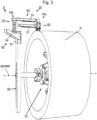
- Fig. 7 is a perspective view of a fourth embodiment of a peeling device according to the invention.
- This includes a clamping assembly 10, to which, via the spindle 16, the peeling arm carrier 160 is attached with its lower, first end 162.
- a peeling assembly 220 with a peeling arm unit 230 is arranged, which essentially corresponds to the structure of the peeling arm unit 130.
- the peeling arm unit 230 differs from the peeling arm unit 130 in the design of the support element 239, which has a substantially L-shaped shape and in which the bores receiving the hinge pins 136b, 138b are arranged at the ends of the L.
- the second end 232b of the peeling arm element 232 is shorter than the second end 234b of the peeling arm element 234, so that one leg of the carrier element 239 has a substantially vertical orientation, while the other leg is aligned approximately horizontally to the peeling arm element 232.
- the distance between the hinge pins 138a, 138b is greater than the distance between the hinge pins 136a, 136b. This changes the orientation of the carrier element 239, and thus also the orientation of the Peeling knife 144 to the tubular body R to be processed while the peeling arm unit 230 is pivoted.
- the hole 239d at the end of the horizontally aligned leg is designed as a part-circular elongated hole, with a circular arc that is concentric to the in Fig. 7a other hole that cannot be seen runs in the support element 239, and the radius of which corresponds to the distance between the centers of these holes, as shown in FIG Fig. 7a circle shown by broken lines.
- the alignment of the paring knife 144 to the tubular body R to be processed can be corrected or adjusted in such a way that the processing of a tubular body R with a conical end is possible.
- a paring knife arrangement 140 with a paring knife 144 is also arranged on the carrier element 239.
- the paring knife 144 is with a fastening element, not shown in detail, on the in Fig. 7a downward-facing side of the carrier element 239 attached.
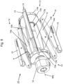
- Fig. 8 shows the clamping assembly 10 according to Figures 1 , 3 and 4 .
- the clamping assembly 10 includes the carrier sleeves 12 with the in Fig. 6 nut 18 attached to the left end and firmly connected to the carrier sleeve 12.
- the first flange 13 is axially fixed, but rotatable about the central axis of the carrier sleeve 12, which is aligned coaxially with the central axis MS of the clamping assembly 10.
- the second flange 13 is arranged to be axially movable on the right end of the carrier sleeve 12.
- the carrier sleeve 12 has the external thread 12a in the area of its right end, which interacts with the corresponding internal thread of the second flange 13.
- the flanges 13 are essentially conical with a cone base 13a and a tapered cone end 13b, the central axis of the flange 13 being aligned coaxially with the central axis of the carrier sleeve 12.
- the tapering ones Cone ends 13b point towards each other.
- the clamping scissor elements 14a, 14b of the clamping scissors 14, which are each articulated in pairs, are arranged in an articulated manner in such a way that they can be pivoted about an axis perpendicular to the central axis MS of the clamping assembly 10.
- approximately U-shaped support elements 15 are arranged, which are aligned in their longitudinal extent at least approximately parallel to the central axis MS of the clamping assembly 10, and have their open side facing the central axis MS of the clamping assembly 10 . Due to their articulated connection to one clamping scissor element 14a, 14b and the connection through an elongated hole to the corresponding other clamping scissor element 14b, 14a, the support elements 15 remain in this orientation. When the peeling device S is ready for use, i.e. when it is assembled, the support elements 15 rest on the inside of the tubular body R.
- a holding element H in the form of a tether is also attached on the clamping assembly 10 the Fig. 6 .
- the holding element or holding band H is fastened with its ends to the cone base 13a of the flanges 13 approximately centrally between two adjacent clamping scissors 14.
- the length of the retaining strap H is chosen so that it is in Fig. 6 shown, relaxed state of the clamping assembly 10, in which the flanges 13 reach their maximum distance from one another, is tensioned between the flanges 13.
- the retaining strap H can also serve as a limit for the maximum possible folding of the clamping assembly 10.
- a fixed handle can also be used as the holding element H, which is attached, for example, with one end to one of the flanges 13 and with its second end extending in the direction of the second flange 13.
- a firm grip could, similar to the support element 15, have a Elongated hole in the area of its other end can be connected to the second flange 13, whereby the mobility of the two flanges 13 is maintained, but the handling of the clamping assembly 10 can be improved.
- Fig. 9 is a sectional view of a second exemplary embodiment of a clamping assembly 310 according to the invention with a central axis MS.
- the clamping assembly 310 comprises a carrier shaft or carrier sleeve 312 designed as a hollow shaft with an in Fig. 9 First flange 313 attached to the left end and firmly connected to the carrier sleeve 312. On the in Fig. 9 At the right end of the carrier sleeve 312, a second flange 313 is arranged axially displaceably on the carrier sleeve 312. The carrier sleeve 312 is arranged coaxially to the central axis MS of the clamping assembly 310.
- the essentially conical flanges 313 have a conical base 313a and a tapered conical end 313b directed towards the center of the carrier sleeve 312.
- pairs of clamping scissor elements 314a, 314b of clamping scissors 314 are arranged in an articulated manner in such a way that they can each be pivoted about an axis perpendicular to the central axis MS of the clamping assembly 310.
- the clamping scissors 314 correspond in their structure and functionality to the clamping scissors 14 of the clamping assembly 10.
- approximately U-shaped support elements 315 are arranged, which are aligned in their longitudinal extent at least approximately parallel to the central axis MS of the clamping assembly 310, and have their open side facing the central axis MS of the clamping assembly 310. They are connected in an articulated manner to one clamping scissor element 314a, 314b and through an elongated hole to the corresponding other clamping scissor element 314b, 314a and therefore remain in this orientation during the actuation of the clamping scissors 314.
- the support elements 315 rest on the inside of the tubular body R.
- the clamping assembly 310 has an actuating mechanism 320.
- the actuating mechanism 320 comprises a piston-cylinder mechanism with an annular piston 322 which is axially fixed on the hollow shaft or carrier sleeve 312 and a sleeve-shaped cylinder 324 which is arranged coaxially to the central axis MS of the clamping assembly 310 on the carrier sleeve 312.
- the cylinder 324 rests with its inner surface on the outer circumferential surface of the piston 322 in a fluid-tight manner and is held displaceably in the axial direction.
- the actuating mechanism 320 further comprises a sleeve-shaped connection element 326 arranged coaxially to the central axis MS of the clamping assembly 310 on the carrier sleeve 312, with a connection section 326a and a fastening section 326b.
- connection section 326a corresponds to the outer diameter of the carrier sleeve 312 and is held slidably thereon.
- the connection section 326a also has a connection bore 326c, to which a fluid source, such as a hydraulic pump, can be connected via a fluid line HS, such as a hydraulic hose.
- the right flange 313 has on its side facing the actuating mechanism 320 a cylindrical recess 313c, which is aligned coaxially with the carrier sleeve 312, the diameter of which corresponds to the outer diameter of the cylinder 324, and into which the right end of the cylinder 324 projects and is fastened there is.
- An annular cylinder space 328 is formed on the outside of the carrier sleeve 312.
- the cylinder space 328 is in fluid communication with the connection bore 326c, so that a fluid conveyed via the fluid line HS reaches the cylinder space 328.
- the flange 313, the cylinder 324 and the connecting element 326 are connected to one another firmly and in a fluid-tight manner. If a fluid is conveyed under pressure into the cylinder space 328 via the fluid line HS, the connecting element 326 with the cylinder 324 and the right flange 313 attached to it shifts accordingly Fig. 9 to the left, whereby the cylinder space 328 is enlarged.
- This movement of the flange 313 activates the clamping scissors 314, which extend radially outwards and clamp the clamping assembly 310 in the tubular body R.
- the fluid under pressure in the cylinder 324 can be relieved by actuating a corresponding backflow valve.
- a backflow valve can be assigned to the fluid source, for example arranged on it.
- it is possible that such a backflow valve is arranged on the actuating mechanism 320 of the clamping assembly 310 or is part of the fluid line HS.
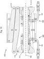
- Fig. 10 a sectional view of a third exemplary embodiment of a clamping assembly 410 according to the invention.
- the clamping assembly 410 like the clamping assembly 310, includes accordingly Fig. 9 , a hollow shaft or carrier sleeve 412, on the in Fig. 10 right end a first flange 413 is displaceably arranged.
- a first actuating mechanism 420 is also arranged on the carrier sleeve 412 and is in its Structure corresponding to that of the clamping assembly 310 Fig. 9 known actuating mechanism 320 corresponds.
- the clamping assembly 410 also includes a further actuation mechanism 420, which is also arranged on the carrier sleeve 412.
- This further actuation mechanism 420 is constructed identically to the first actuation mechanism 420, but arranged in mirror image thereto, and with the in Fig. 10 left flange 413 connected.
- Clamping scissors 414 are arranged on the flanges 413 and are constructed identically to the clamping scissors 314 of the clamping assembly 310.
- both actuation mechanisms 4320 are each connected to a fluid source via a fluid line HS. It is possible that both fluid lines HS are connected to the same source and can either be controlled together or separately. The actuation can take place simultaneously or one after the other.
- Fig. 11 shows a sectional view of a fourth exemplary embodiment of a clamping assembly 510 according to the invention.
- the structure of the first flange 513 essentially corresponds to the first flange 312 according to the second exemplary embodiment of the clamping assembly 310 Fig. 9 .
- the clamping assembly 510 also points to the in Fig. 11 left end of the carrier sleeve 512 has a fixed second flange 513.
- Clamping scissors 514 are arranged on the flanges 512, the structure and functioning of which correspond to the clamping scissors 314 of the clamping assembly 310.
- the clamping assembly 510 has an actuation mechanism 520.
- the actuating mechanism 520 comprises a piston-cylinder mechanism with an annular piston 522 which is axially fixed on the carrier sleeve 512 and a sleeve-shaped cylinder 524 which is coaxial with the Central axis MS of the clamping assembly 510 is arranged on the carrier sleeve 512 in a fluid-tight manner.
- the cylinder 524 rests with its inner surface on the outer surface of the piston 522 and is held displaceably in the axial direction.
- the actuating mechanism 520 further comprises a sleeve-shaped connection element 526 arranged coaxially to the central axis MS of the clamping assembly 510 on the carrier sleeve 512, with a connection section 526a, a fastening section 526b and a cylinder sleeve in the form of a tubular section 526c.
- the inner diameter of the in Fig. 11 The right end of the support sleeve 512 facing fastening section 526b of the connecting element 526 corresponds to the outer diameter of the cylinder 524, the left end of which is received in the fastening section 526b and fastened thereto in a fluid-tight manner.
- the inner diameter of the connection section 526a corresponds to the outer diameter of the carrier sleeve 512 and is held slidably thereon.
- the tubular section 526c adjoins the in Fig. 11 right end of the fastening section 526b and extends towards the right flange 513.
- the inner diameter of the cylinder sleeve or the tubular section 526c is larger than the outer diameter of the cylinder 524.
- the right flange 513 has on its side facing the actuating mechanism 520 a first cylindrical recess 513c, the diameter of which corresponds to the outer diameter of the cylinder 524, and into which the right end of the cylinder 524 projects and is fastened there.
- An annular cylinder space 528 is formed between the piston 522 and the end face of the connecting section 526a of the connecting element 526 facing the piston 522 on the one hand and the inside of the left end of the cylinder 524 and the outside of the carrier sleeve 512 opposite this surface.
- the flange 513 has a second cylindrical recess 513d on its side facing the actuating mechanism 520, which is aligned coaxially with the first recess 513c, the diameter of which corresponds to the outer diameter of the tubular section 526c of the connecting element 526, which projects into it and is fastened there.
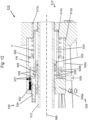
- the actuation mechanism 520 further includes an integrated drive for actuating the clamping assembly 520, as described below in connection with Fig. 12 is explained, which is an enlarged view of the actuating mechanism 520 of the clamping assembly 510 accordingly Fig. 11 is.
- the drive of the actuation mechanism 520 includes a fluid pump 530 with a piston 532 that can be moved in a cylinder 534.
- the cylinder 534 is arranged in the connection section 526a of the connection element 526, and extends parallel to the central axis MS of the clamping assembly 520 from in Fig. 12 left end of the connection element 526 to the right into the connection section 526a.
- An annular cavity is formed between the outer surface of the cylinder 524 of the piston-cylinder assembly and the inner surface of the tubular portion 526c.
- An annular piston 540 is arranged in the cavity, which sits slidably on the outer surface of the cylinder 524 and rests with its outer peripheral surface on the inner surface of the tubular section 526c of the connecting element 526.
- the annular piston 540 divides the annular cavity.
- a fluid reservoir FR is formed on the side of the annular piston 540 facing the fluid pump 530.
- the fluid reservoir or reservoir FR is connected to the cylinder 532 of the fluid pump 530 and the annular cylinder space 528 via channels 536 arranged in the connecting element 526.
- Check valves 537 in the form of spring-loaded ball check valves are arranged in the channels 536, which prevent fluid from flowing back through the channels 536 into the reservoir FR.
- connection element 536 there are further channels 538 which connect the annular cylinder space 528 with the reservoir FR.
- a return flow valve 539 is arranged in the channels 538, which allows fluid to flow back from the annular cylinder space 528 into the reservoir FR.
- a spring element F in the form of a helical compression spring is arranged on the right side of the annular piston 540.
- the spring element or spring F is arranged coaxially on the cylinder 524 and generates a force acting on the annular piston 540 in the axial direction.
- the annular cavity to the right of the annular piston 540 is connected to the atmosphere via a corresponding ventilation hole 513e in the flange 513.
- a lever H is provided.
- the lever H is on the in Fig. 13 left-facing end face of the connecting element 526 is articulated, and connected at its lower end to the piston 534 of the fluid pump 530, so that the piston 534 can be reversibly moved back and forth by actuating the lever H in the cylinder 532.
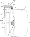
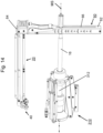
- Fig. 14 is a schematic, perspective view of a peeling device with a peeling assembly Fig. 3 and a clamping assembly Fig. 9 .
- a spindle such as the threaded spindle 16 extends through the hollow shaft or carrier sleeve 312 of the clamping assembly 310 and protrudes from the in Fig. 14 right end of the clamping assembly 310.
- the right end of the spindle 16 extends through the elongated hole 66 of the peeling arm carrier 60 which is attached thereto.
- the peeling assembly 20 with the peeling knife arrangement 40 is arranged, which extends at least approximately parallel to the central axis MS of the clamping assembly 310. How further in Fig.
- the peeling arm carrier 60 can also be provided with markings which are arranged along the elongated hole 66, and the indicate the attachment position of the peeling arm carrier 60 on the clamping assembly 310 with respect to the diameter of a tubular body R to be processed.
- the clamping assembly 10 is first positioned inside the tubular body R and clamped in such a way that the central axis MS of the clamping assembly 10 is at least approximately coaxial with the Central axis MR of the tubular body R is aligned.
- the threaded spindle 16 with the peeling arm carrier 60 and the peeling arm unit 30 located thereon is then inserted into the carrier sleeve 12, so that the peeling knife arrangement 40 is positioned radially over the section of the tubular body R to be peeled.
- a lock can be provided on the carrier sleeve 12 or the nut 18, which prevents unwanted axial displacement of the threaded spindle.
- the connection between the peeling arm carrier 60 and the left end 16a of the threaded spindle 16 is released.
- the peeling arm carrier 60 can now be moved along the end 16a of the threaded spindle 16 over the elongated hole 66 until the peeling assembly 20 or the knife carriage 42 of the peeling knife arrangement 40 with the rollers 46 stands on the tubular body R, and the peeling arm elements 32, 34 the peeling arm unit 30 are aligned at least approximately parallel to the central axis MR of the tubular body R.
- the peeling arm carrier 60 is then fixed in this position on the threaded spindle 16.
- the spring element 54 is biased by moving the pressure plate 52, for example manually, towards the second end 64 of the peeling arm carrier 60.
- the peeling arm unit 30 is not yet in the in Fig. 1 shown peeling position, ie, the spring element 54 is in an unloaded state.
- the peeling arm unit is then placed on the tubular body R and the spring element 54 is further prestressed. Due to the force exerted by the elastic element 54 on the pressure plate 52, the pressure plate 52 tilts on the peeling arm carrier 60 and is thus secured against slipping.
- a clamp (not shown) can be provided which secures the pressure plate 52 in its position on the peeling arm carrier 60, for example against unintentional displacement when load changes may occur.
- the clamping lever 84 which is located before the peeling assembly 20 is brought to the surface of the tubular body R in the in Fig. 3 in the open position shown in Fig. 4 shown clamping position, whereby the pressure plate 72 is moved towards the second end 64 of the peeling arm carrier 60.
- the force generated by the force application unit or biasing device 50, 70, with which the knife carriage 42 is pressed onto the surface of the tubular body R should be greater than the force with which the paring knife 44 is pressed against the knife carriage 42 by the spring element located in the knife carriage 42 Pipe surface is pressed to prevent the knife carriage 42 from being lifted off the tubular body R. This ensures that any existing ovalities in the tubular body R are reliably compensated for and ensures that the paring knife 44 rests on the tubular body R with a constant force.
- the peeling arm carrier 160 can be attached to the spindle 16 in the same way.
- the spindle 16 can thus be easily attached to the marking corresponding to the diameter of the tubular body R to be machined.
- the adjusting screw 152 of the force application unit or biasing unit 150 is actuated.
- the spring 154 acting on the first end 134a of the peeling arm element 134 is relieved.
- the peeling knife assembly 140 can move further towards the surface of the tubular body R, but a radial springback requires less force than with a more strongly preloaded spring F. If, on the other hand, the spring F is further tensioned by screwing the adjusting screw into the peeling arm carrier 160, a greater force is necessary for further compression.
- the peeling device S with the peeling assembly 20 is driven to rotate around the tubular body R. This can be done manually if, for example, a handle is provided in the area of the second end 64 of the peeling arm carrier 60.
- a handle is provided in the area of the second end 64 of the peeling arm carrier 60.
- an electrical device such as a cordless screwdriver or a drill, which can be attached to the attachment point of the threaded spindle 16 on the peeling arm carrier 60 using a corresponding adapter.
- the position of the peeling assembly 20 can be adjusted or changed along the central axis MS of the clamping element 10 or the central axis R of the tubular body R. This can be done gradually or continuously.
- care must be taken to ensure that the feed length corresponds at most to the width of the paring knife 44 in order to achieve uniform material removal in the axial direction. If the axial feed is continuous, it should this also corresponds to a maximum of the width of the peeling knife 44 during one revolution of the peeling assembly 20 around the tubular body R.
- a gradual axial advance can be achieved by releasing the connection between the peeling arm support 60 and the threaded spindle 16 after each revolution of the peeling assembly 20 about the tubular body R, and the peeling arm support 60 on the threaded spindle 16 by a corresponding amount along the central axis MR of the tubular body R is moved and fixed again.
- the threaded spindle 16 screws into or through the clamping assembly 10 by a desired length with each revolution of the peeling assembly 20 around the tubular body R.
- the clamping assembly 10 can, for example, have a corresponding threaded sleeve which receives the threaded spindle 16.
- the peeling arm carrier 60 is attached to the end 16a of the spindle 16 in a radially fixed manner but rotatable about the central axis MS of the clamping assembly 10.
- the threaded spindle 16 is manually screwed into or through the clamping assembly 10 by a desired length after each revolution of the peeling assembly 20 around the tubular body R.
- the peeling device S according to the invention can also be equipped with a clamping assembly 310, 410, 510, the operation of which is explained below.
- the clamping assembly 310 according to the in connection with Fig. 9
- the second exemplary embodiment explained is inserted coaxially into the tubular body R to be processed.
- a pressurized fluid such as hydraulic oil
- the pressurized fluid moves the connecting element 326 axially away from the piston 322, which is fixedly arranged on the carrier sleeve 312.
- the flange 313, which is also firmly connected to the cylinder 324 is also displaced on the carrier sleeve 312.
- the support elements 315 move radially away from the central axis MS of the clamping assembly 310 until they rest on the inside of the tubular body R and clamp the clamping assembly 310 therein.
- the clamping assembly 410 accordingly Fig. 10 includes two actuation mechanisms 420. These function in the same manner as the actuation mechanism 320 of the clamping assembly 310.
- the actuation mechanisms 420 of the clamping assembly 410 can be actuated individually, whereby only one of the flange 413 at a time, as in connection with Fig. 9 described, is moved on the carrier sleeve 312. It may be sufficient to activate only one of the actuation mechanisms 420. However, both actuation mechanisms 420 can also be activated one after the other. In addition, it is also possible to activate both actuation mechanisms 420 simultaneously in order to clamp the clamping assembly 410 in the tubular body R to be machined.
- the pressurized fluid is relieved by allowing backflow into the fluid source.
- the clamping scissors 314, 414 relieved in this way can be pushed together manually.
- the clamping assembly 510 is held coaxially in the tubular body R to be machined.
- the lever H is moved back and forth, whereby the fluid pump 530 is actuated.
- fluid such as hydraulic oil
- the check valves 537 arranged in the channels 536 prevent backflow of pressurized fluid into the reservoir FR during the clamping of the clamping assembly 510.
- the pressurized fluid causes the connecting element 526 to move axially away from that on the carrier sleeve 512 fixed piston 522 moved away.
- the flange 513 is also displaced on the carrier sleeve 512.
- the clamping scissors 514 are activated and the clamping assembly 510 is clamped in the tubular body R.
- the return flow valve 539 is activated, whereby the pressurized fluid located in the annular cylinder space 528 can flow back into the fluid reservoir FR via the channels 538.
- the clamping scissors 514 can be manually compressed.
- the size of the fluid reservoir FR changes in accordance with the amount of fluid removed or returned, with the annular piston 540 being moved accordingly.
- the spring F acting on the side of the annular piston 540 facing away from the fluid reservoir FR prevents the annular piston 540 from tilting and air from penetrating into the hydraulic system.
- Clamping assemblies 310, 410, 510 described are fluid-operated. It is therefore understood that between the relatively movable elements of the assemblies that come into contact with the fluid, corresponding seals are provided, which prevent an unwanted leakage of fluid or an equally unwanted penetration of outside air into the fluid system.
- the peeling arm carrier 60, 160 is in the exemplary embodiments Figures 1 to 7 shown with a substantially square cross section. Of course, it is possible for the peeling arm carrier 60, 160 to have a different cross section, for example a square, triangular or round cross section.
- additional positive locking means can be provided in order to To further stabilize the peeling arm carrier 60, 160, and above all to avoid unwanted twisting of the peeling arm carrier 60, 160 about an axis in its longitudinal extent, such as sleeves or clamps that prevent the peeling arm carrier 60, 160 from tilting relative to the threaded spindle 16.
- a further pressure plate is provided at the second end 64 of the peeling arm carrier 60, which is arranged between the first end 34a of the peeling arm element 34 and the elastic element 54.
- the securing and positioning element 56, 76 is arranged on this further pressure plate.
- a spindle acting on this pressure plate, or a similarly acting element can be attached to the first end 34a of the peeling arm element 34, which can be moved, for example, by means of a corresponding knob in order to move the pressure plate in the direction of the elastic element 54 in order to achieve a further adjustment of the preload must be made.
- all elements of the peeling device according to the invention can be made of a suitable metal, such as steel or aluminum, in order to ensure the required strength.
- a suitable metal such as steel or aluminum
- the second flange 13 has an internal thread which cooperates with a corresponding external thread on the right end of the carrier sleeve 12 in order to move the flange 13 on the carrier sleeve 12 in the axial direction for tensioning and relaxing the clamping scissors 14.
- the axial mobility of the second flange 13 can be achieved using other means.
- the right side of the carrier sleeve 12 can be designed as a hydraulic or pneumatic piston, on which the second flange 13, designed as a hydraulic or pneumatic cylinder, can be reversibly moved by means of a corresponding hydraulic or pneumatic pump.
- a peeling device S comprises a clamping assembly, a peeling arm carrier and a peeling assembly with a peeling arm unit. It is possible to combine each clamping assembly 10, 310, 410, 510 with each of the peeling arm supports 60,160 and each of the peeling arm units 30,130, 230.
- clamping assemblies 10, 310, 410, 510 in addition to a peeling tool, generally as a tool holder for any type of tool for processing an approximately tubular body, such as a pipe cutter or a thread cutter.
- a peeling tool generally as a tool holder for any type of tool for processing an approximately tubular body, such as a pipe cutter or a thread cutter.
- it can be arranged directly on the clamping assembly 10, 310, 410, 510 or on the peeling arm carrier 60,160.
- Peeling device for at least partially removing the surface of an at least approximately tubular body with a central axis, in particular a plastic pipe, comprising: a clamping assembly with a central axis and at least one clamping element for clamping the peeling device on the tubular body, the central axis of the in the assembled state Clamping assembly coincides at least approximately with the central axis of the tubular body, and a peeling assembly with a peeling arm unit, a peeling knife arrangement arranged at a first end of the peeling arm unit and a peeling arm carrier with a first end and a second end which connects the clamping assembly to the peeling arm unit, wherein the Peeling arm unit with a second end is connected to the peeling arm carrier in such a way that the peeling arm unit and the central axis of the clamping assembly lie in a common plane in the assembled state, the peeling knife arrangement having a peeling knife, the peeling arm unit having its first and second ends in this way with the peeling knife arrangement and connected to
- Example 2 Peeling device according to Example 1, further comprising a force application unit for reversibly biasing the peeling arm unit in a peeling position in a direction in the common plane of the peeling arm unit and the central axis of the clamping assembly.
- Example 3 Peeling device according to one of Examples 1 or 2, wherein the clamping assembly has more than one clamping element, preferably three clamping elements, preferably in the form of clamping scissors.
Abstract
Die Erfindung betrifft ein Schälgerät (S) zum zumindest teilweise Abtragen der Oberfläche eines wenigstens annähernd rohrförmigen Körpers (R) mit einer Mittelachse (MR), insbesondere eines Kunststoffrohrs, aufweisend: eine Spannbaugruppe (10; 310; 410; 510) mit einer Mittelachse (MS) und wenigstens einem Spannelement (14, 314, 414, 514) zum Verspannen des Schälgeräts (S) an dem rohrförmigen Körper (R), eine Schälbaugruppe (20) mit einer Schälarmeinheit (30, 130, 230), einer an einem ersten Ende (30a, 130a, 230a) der Schälarmeinheit (30) angeordneten Schälmesseranordnung (40, 140) und einem Schälarmträger (60, 160), der die Spannbaugruppe (10; 310; 410; 510) mit der Schälarmeinheit (30, 130, 230) verbindet. Die Schälarmeinheit (30, 130, 230) ist mit ihren ersten und zweiten Enden (30a, 130a, 230a; 30b, 130b, 230b) derart mit der Schälmesseranordnung (40, 140) und dem Schälarmträger (60, 160) verbunden und in der gemeinsamen Ebene mit der Mittelachse (MS) der Spannbaugruppe (10; 310; 410; 510) verschwenkbar, dass die Schälmesseranordnung (40, 140) in jeder Schwenkposition der Schälarmeinheit (30, 130, 230) ihre Ausrichtung zur Mittelachse (MS) der Spannbaugruppe (10, 310, 410, 510) beibehält. Die Erfindung betrifft weiterhin ein Spannbaugruppe (10; 110; 210; 310) als Werkzeugträger für ein Werkzeug, wie ein Schälwerkzeug, zur Bearbeitung eines annähernd rohrförmigen Körpers (R) mit einer Mittelachse (MR), insbesondere eines Kunststoffrohres, aufweisend eine Mittelachse (MS), eine koaxial zur Mittelachse (MS) der Spannbaugruppe (10, 310, 410, 510) angeordneten Trägerwelle (12, 312, 412, 512), und wenigstens eine, auf der Trägerwelle (12, 312, 412, 512) angeordneten, und im Wesentlichen radial nach außen gerichteten Spanneinrichtung (13, 14; 313, 314; 413, 414; 513, 514).The invention relates to a peeling device (S) for at least partially removing the surface of an at least approximately tubular body (R) with a central axis (MR), in particular a plastic pipe, comprising: a clamping assembly (10; 310; 410; 510) with a central axis ( MS) and at least one clamping element (14, 314, 414, 514) for clamping the peeling device (S) on the tubular body (R), a peeling assembly (20) with a peeling arm unit (30, 130, 230), one on a first A peeling knife arrangement (40, 140) arranged at the end (30a, 130a, 230a) of the peeling arm unit (30) and a peeling arm carrier (60, 160) which connects the clamping assembly (10; 310; 410; 510) to the peeling arm unit (30, 130, 230 ) connects. The peeling arm unit (30, 130, 230) is connected with its first and second ends (30a, 130a, 230a; 30b, 130b, 230b) to the peeling knife arrangement (40, 140) and the peeling arm carrier (60, 160) and in the common plane with the central axis (MS) of the clamping assembly (10; 310; 410; 510) so that the peeling knife arrangement (40, 140) is aligned with the central axis (MS) of the clamping assembly in each pivoting position of the peeling arm unit (30, 130, 230). (10, 310, 410, 510) is retained. The invention further relates to a clamping assembly (10; 110; 210; 310) as a tool carrier for a tool, such as a peeling tool, for machining an approximately tubular body (R) with a central axis (MR), in particular a plastic tube, having a central axis (MS ), a carrier shaft (12, 312, 412, 512) arranged coaxially to the central axis (MS) of the clamping assembly (10, 310, 410, 510), and at least one arranged on the carrier shaft (12, 312, 412, 512), and essentially radially outwardly directed tensioning device (13, 14; 313, 314; 413, 414; 513, 514).
Description
Die vorliegende Erfindung betrifft ein Schälgerät zum zumindest teilweise Abtragen der Oberfläche eines zumindest annähernd rohrförmigen Körpers sowie eine Spannbaugruppe als Werkzeugträger für ein Werkzeug, wie eine Schälmesseranordnung eines Schälgeräts, zur Bearbeitung eines annähernd rohrförmigen Körpers.The present invention relates to a peeling device for at least partially removing the surface of an at least approximately tubular body and to a clamping assembly as a tool carrier for a tool, such as a peeling knife arrangement of a peeling device, for processing an approximately tubular body.
Insbesondere betrifft die vorliegende Erfindung ein Schälgerät zum zumindest teilweise Abtragen der Oberfläche eines zumindest annähernd rohrförmigen Körpers mit einer Mittelachse, insbesondere eines Kunststoffrohrs, mit einer Spannbaugruppe aufweisend eine Mittelachse und wenigstens ein Spannelement zum Verspannen des Schälgeräts an dem rohrförmigen Körper, wobei im montierten Zustand, die Mittelachse der Spannbaugruppe zumindest annähernd mit der Mittelachse des rohrförmigen Körpers zusammenfällt, und mit einer Schälbaugruppe aufweisend eine Schälarmeinheit, eine an einem ersten Ende der Schälarmeinheit angeordnete Schälmesseranordnung und einen Schälarmträger, der die Spannbaugruppe mit der Schälarmeinheit verbindet, wobei die Schälarmeinheit mit einem zweiten Ende mit dem Schälarmträger derart verbunden ist, dass die Schälarmeinheit und die Mittelachse der Spannbaugruppe in einer gemeinsame Ebene liegen, wobei die Schälmesseranordnung ein Schälmesser aufweist.In particular, the present invention relates to a peeling device for at least partially removing the surface of an at least approximately tubular body with a central axis, in particular a plastic pipe, with a clamping assembly having a central axis and at least one clamping element for clamping the peeling device on the tubular body, wherein in the assembled state, the central axis of the clamping assembly coincides at least approximately with the central axis of the tubular body, and with a peeling assembly comprising a peeling arm unit, a peeling knife arrangement arranged at a first end of the peeling arm unit and a peeling arm carrier which connects the clamping assembly to the peeling arm unit, the peeling arm unit having a second end is connected to the peeling arm carrier in such a way that the peeling arm unit and the central axis of the clamping assembly lie in a common plane, the peeling knife arrangement having a peeling knife.
Die vorliegende Erfindung betrifft ferner eine Spannbaugruppe als Werkzeugträger für ein Werkzeug, wie eine Schälmesseranordnung eines Schälgeräts, zur Bearbeitung eines annähernd rohrförmigen Körpers mit einer Mittelachse, insbesondere eines Kunststoffrohres. Die Spannbaugruppe weist eine Mittelachse, eine koaxial zur Mittelachse der Spannbaugruppe angeordneten Trägerwelle und wenigstens eine, auf der Trägerwelle angeordneten, und im Wesentlichen radial nach au-βen gerichteten Spanneinrichtung auf.The present invention further relates to a clamping assembly as a tool carrier for a tool, such as a peeling knife arrangement of a peeling device, for processing an approximately tubular body with a central axis, in particular a plastic tube. The clamping assembly has a central axis, a carrier shaft arranged coaxially to the central axis of the clamping assembly and at least one clamping device arranged on the carrier shaft and directed essentially radially outwards.
Zum Aufbau von Netzen für die Versorgung von Verbrauchern mit beispielsweise Wasser oder Gase ist es in der Praxis bekannt, hierzu Kunststoffrohre zu verwenden. Zur Erstellung eines Netzes, bei dem große Distanzen zu überbrücken sind und/oder das eine Vielzahl an Abzweigungen aufweist, werden die Kunststoffrohre an ihren Enden miteinander oder mit anderen Formteilen, wie T- oder Kreuzstücken, beispielsweise über Heizwendelfittinge im Wege einer Heizwendelverschweißung verbunden. Um eine dichte Verschweißung sicherzustellen, wird die Außenoberflächen der Kunststoffrohre an denjenigen Stellen, an denen eine Verschweißung mit einem Formteil oder dgl. erfolgen soll, vor der eigentlichen Verschweißung geringfügig abgetragen.To set up networks for supplying consumers with water or gases, for example, it is known in practice to use plastic pipes for this purpose. To create a network in which large distances have to be bridged and/or which has a large number of branches, the plastic pipes are connected at their ends to one another or to other shaped parts, such as T-pieces or cross pieces, for example via heating coil fittings by means of heating coil welding. In order to ensure a tight weld, the outer surfaces of the plastic pipes are slightly removed before the actual welding in those places where welding with a molded part or the like is to take place.
Dabei ist zu berücksichtigen, dass Kunststoffrohre, bzw. deren Enden, nicht immer exakt zylindrisch sind, sondern Ovalitäten aufweisen können. Zudem kann die Oberfläche solcher Kunststoffrohre weitere Unebenheiten, wie Kratzer oder Riefen, oder chemische Veränderungen, wie Oxidation oder Kontamination, aufweisen, die eine sichere und/oder mediendichte Verbindung zwischen dem rohrförmigen Körper und dem darauf aufgesetzten Formstück verhindern können, oder zumindest die Qualität dieser Verbindung beeinträchtigen. Es ist daher üblich, die Abschnitte des rohrförmigen Körpers, auf denen ein solches Formstück aufgesetzt werden soll, mittels eines Schälgeräts zu bearbeiten, um solche Unebenheiten oder Veränderungen in der rohrförmigen Körperoberfläche zu beseitigen.It should be noted that plastic pipes or their ends are not always exactly cylindrical, but can have ovalities. In addition, the surface of such plastic pipes can have further unevenness, such as scratches or grooves, or chemical changes, such as oxidation or contamination, which can prevent a secure and/or media-tight connection between the tubular body and the fitting placed on it, or at least the quality of this affect connection. It is therefore customary to process the sections of the tubular body on which such a shaped piece is to be placed using a peeling device in order to eliminate such unevenness or changes in the tubular body surface.
Aus dem
Andere bekannte Schälgeräte zum Abtragen von Material von der Oberfläche eines Kunststoffrohrs sind im wesentlichen C-förmig ausgebildet und weisen eine zu ihrer Innenseite gerichtete Schaberklinge auf. Ein solches Schälgerät ist aus der
Nachteilig an diesen bekannten Vorrichtungen ist, dass bei nicht exakt zylindrischen rohrförmigen Körpern nur unzureichend oder kein Material abgetragen wird, da die Schaberklingen aufgrund der Ovalität des rohrförmigen Körpers abheben oder nicht mit ausreichendem Druck anliegen, um einen gewünschten Materialabtrag zu gewährleisten. Auch ist eine exakte Positionierung der Bearbeitungswerkzeuge zu dem zu bearbeitenden Abschnitt des rohrförmigen Körpers nicht in jedem Fall möglich, was aber für eine qualitativ hochwertige Bearbeitung des rohrförmigen Körpers notwendig ist. Insgesamt besteht hier die Gefahr, dass der bearbeitete Bereich nur unzureichend geglättet wird, oder dass kein ausreichender Materialabtrag erzielt wird, was einer qualitativ hochwertigen Verbindung zwischen dem rohrförmigen Körper und dem Formstück entgegenstehen kann.The disadvantage of these known devices is that in the case of tubular bodies that are not exactly cylindrical, only insufficient or no material is removed because the scraper blades lift off due to the ovality of the tubular body or do not apply with sufficient pressure to ensure the desired removal of material. An exact positioning of the processing tools in relation to the section of the tubular body to be processed is not always possible, but this is necessary for high-quality processing of the tubular body. Overall, there is a risk that the machined area will not be sufficiently smoothed or that insufficient material removal will be achieved, which can prevent a high-quality connection between the tubular body and the fitting.
Es ist daher die Aufgabe der vorliegenden Erfindung, ein Schälgerät bereitzustellen, das die vorstehend genannten Nachteile überwindet, und eine Bearbeitung eines zylindrischen Körpers, wie eines Kunststoffrohrs, in einer Weise ermöglicht, dass eine qualitativ hochwertige Verbindung zwischen dem rohrförmigen Körper und dem Formstück entsteht. Es ist weiterhin Aufgabe der vorliegenden Erfindung, einen Werkzeugträger, wie eine Spannbaugruppe, bereitzustellen, die eine exakte Positionierung eines an dem Werkzeugträger befestigten Bearbeitungswerkzeugs relativ zu dem zu bearbeitenden rohrförmigen Körper ermöglicht.It is therefore the object of the present invention to provide a peeling device which overcomes the above-mentioned disadvantages and enables processing of a cylindrical body, such as a plastic pipe, in a manner that a high-quality connection between the tubular body and the fitting is created. It is a further object of the present invention to provide a tool carrier, such as a clamping assembly, which enables precise positioning of a machining tool attached to the tool carrier relative to the tubular body to be machined.
Diese Aufgaben werden durch ein Schälgerät sowie eine Spannbaugruppe als Werkzeugträger für ein Werkzeug, wie eine Schälmesseranordnung eines Schälgeräts entsprechend der vorliegenden Erfindung gelöst. Vorteilhafte Ausgestaltungen mit zweckmäßigen Weiterbildungen sind in den davon abhängigen Ansprüchen angegeben.These tasks are achieved by a peeling device and a clamping assembly as a tool carrier for a tool, such as a peeling knife arrangement of a peeling device according to the present invention. Advantageous refinements with useful further developments are specified in the dependent claims.
Erfindungsgemäß wird ein Schälgerät vorgeschlagen, zum zumindest teilweise Abtragen der Oberfläche eines wenigstens annähernd rohrförmigen Körpers mit einer Mittelachse, insbesondere eines Kunststoffrohrs, mit einer Spannbaugruppe aufweisend eine Mittelachse und wenigstens ein Spannelement zum Verspannen des Schälgeräts an dem rohrförmigen Körper, wobei im montierten Zustand die Mittelachse der Spannbaugruppe zumindest annähernd mit der Mittelachse des rohrförmigen Körpers zusammenfällt, und mit einer Schälbaugruppe aufweisend eine Schälarmeinheit, eine an einem ersten Ende der Schälarmeinheit angeordnete Schälmesseranordnung und einen Schälarmträger mit einem ersten Ende und einem zweiten Ende, der die Spannbaugruppe mit der Schälarmeinheit verbindet, wobei die Schälarmeinheit mit einem zweiten Ende mit dem Schälarmträger derart verbunden ist, dass die Schälarmeinheit und die Mittelachse der Spannbaugruppe im montierten Zustand in einer gemeinsame Ebene liegen. Die Schälmesseranordnung weist ein Schälmesser auf, das an einem ersten Ende der Schälarmeinheit angeordnet ist.According to the invention, a peeling device is proposed for at least partially removing the surface of an at least approximately tubular body with a central axis, in particular a plastic pipe, with a clamping assembly having a central axis and at least one clamping element for clamping the peeling device on the tubular body, the central axis in the assembled state the clamping assembly at least approximately coincides with the central axis of the tubular body, and with a peeling assembly comprising a peeling arm unit, a peeling knife arrangement arranged at a first end of the peeling arm unit and a peeling arm carrier with a first end and a second end which connects the clamping assembly to the peeling arm unit, wherein the peeling arm unit is connected at a second end to the peeling arm carrier in such a way that the peeling arm unit and the central axis of the clamping assembly lie in a common plane in the assembled state. The peeling knife arrangement has a peeling knife which is arranged at a first end of the peeling arm unit.
Weiterhin ist erfindungsgemäß vorgesehen, dass die Schälarmeinheit mit ihren ersten und zweiten Enden derart mit der Schälmesseranordnung und dem Schälarmträger verbunden und in der gemeinsamen Ebene mit der Mittelachse der Spannbaugruppe verschwenkbar ist, dass der Messerwagen in jeder Schwenkposition der Schälarmeinheit seine Ausrichtung zur Mittelachse der Spannbaugruppe beibehält.Furthermore, it is provided according to the invention that the peeling arm unit is connected with its first and second ends to the peeling knife arrangement and the peeling arm carrier and can be pivoted in the common plane with the central axis of the clamping assembly so that the knife carriage maintains its alignment with the central axis of the clamping assembly in every pivoting position of the peeling arm unit .
Hierdurch kann sichergestellt werden, dass ein Schälmesser einer Schälmesseranordnung zu jedem Bearbeitungszeitpunkt seine Ausrichtung zu dem zu bearbeitenden rohrförmigen Körper beibehält, wodurch ein gleichmäßiger Materialabtrag und eine hohe Oberflächenqualität gewährleistet werden können.This can ensure that a paring knife of a paring knife arrangement maintains its alignment with the tubular body to be machined at every processing time, whereby uniform material removal and a high surface quality can be guaranteed.
Die Schälmesseranordnung kann dabei auf unterschiedliche Weise gestaltet sein. In einer vorteilhaften Ausgestaltung weist die Schälmesseranordnung einen Messerwagen mit einem darin bzw. daran angeordneten Schälmesser auf, der am Ende der Schälarmeinheit angeordnet ist. Ein solcher Messerwagen kann eine exakte Führung des Schälmessers gewährleisten.The paring knife arrangement can be designed in different ways. In an advantageous embodiment, the peeling knife arrangement has a knife carriage with a peeling knife arranged therein or on it, which is arranged at the end of the peeling arm unit. Such a knife carriage can ensure precise guidance of the paring knife.
Dabei können die Schwenkachsen auf unterschiedliche Weise realisiert werden. In einer Ausführung kann vorgesehen sein, dass die Schwenkachsen durch Gelenkbolzen gebildet werden, die in entsprechenden Bohrungen aufgenommen sind.The pivot axes can be implemented in different ways. In one embodiment it can be provided that the pivot axes are formed by hinge pins which are accommodated in corresponding bores.
In einer bevorzugten Ausgestaltung kann vorgesehen sein, das die Schälarmeinheit wenigstens zueinander parallel angeordnete erste und zweite Schälarmelemente mit ersten und zweiten Enden aufweist, die schwenkbar mit der Schälmesseranordnung und dem Schälarmträger verbunden sind, mit senkrecht zur gemeinsamen Ebene der Schälarmeinheit und der Mittelachse der Spannbaugruppe ausgerichteten Schwenkachsen.In a preferred embodiment, it can be provided that the peeling arm unit has at least mutually parallel first and second peeling arm elements with first and second ends, which are pivotally connected to the peeling knife arrangement and the peeling arm carrier, with oriented perpendicular to the common plane of the peeling arm unit and the central axis of the clamping assembly Swivel axes.
Diese Ausgestaltung ermöglicht es der Schälmesseranordnung bzw. dem Messerwagen, Ovalitäten des zu bearbeitenden rohrförmigen Körpers auszugleichen und sich gleichzeitig dem reduzierten bzw. sich reduzierenden Durchmesser des bearbeiteten rohrförmigen Körpers anzupassen. Die Ausrichtung der Schälmesseranordnung bzw. des Messerwagens, und somit die Ausrichtung des Schälmessers, zur rohrförmigen Körperachse bleibt dabei erhalten.This configuration enables the peeling knife arrangement or the knife carriage to compensate for ovalities of the tubular body to be processed and at the same time to adapt to the reduced or reducing diameter of the processed tubular body. The alignment of the paring knife arrangement or the knife carriage, and thus the alignment of the paring knife, to the tubular body axis is retained.
Weiterhin ist es von Vorteil, wenn die Schälarmelemente in radialer Richtung, bezogen auf die Mittelachse der Spannbaugruppe, übereinander angeordnet sind, wodurch deine Bewegung des Messerwagens ausschließlich in der gemeinsamen Ebene der Schälarmeinheit und der Mittelachse der Spannbaugruppe sichergestellt werden kann.Furthermore, it is advantageous if the peeling arm elements are arranged one above the other in the radial direction, relative to the central axis of the clamping assembly, whereby your movement of the knife carriage exclusively in the common direction Level of the peeling arm unit and the central axis of the clamping assembly can be ensured.
In einer vorteilhaften Ausgestaltung der erfindungsgemäßen Schäleinheit ist vorgesehen, dass die Abstände der Schwenkachsen in radialer Richtung, bezogen auf die Mittelachse der Spannbaugruppe und in axialer Richtung, bezogen auf die Mittelachse der Spannbaugruppe, gleich groß sind, sodass die Schwenkachsen in der gemeinsamen Ebene der Schälarmeinheit und der Mittelachse der Spannbaugruppe die Eckpunkte eines Parallelogramms bilden. Hierdurch wird die gewünschte Bewegung der Schälmesseranordnung relativ zu dem rohrförmigen Körper erreicht.In an advantageous embodiment of the peeling unit according to the invention, it is provided that the distances between the pivot axes in the radial direction, relative to the central axis of the clamping assembly, and in the axial direction, relative to the central axis of the clamping assembly, are the same size, so that the pivot axes are in the common plane of the peeling arm unit and the central axis of the clamping assembly form the corner points of a parallelogram. This achieves the desired movement of the paring knife arrangement relative to the tubular body.
In einer weiterhin vorteilhaften Ausgestaltung der Schälarm-einheit kann erfindungsgemäß vorgesehen sein, dass die Abstände der Schwenkachsen in radialer Richtung, bezogen auf die Mittelachse der Spannbaugruppe, gleich groß sind, aber in axialer Richtung, bezogen auf die Mittelachse der Spannbaugruppe, unterschiedlich groß sind. Entsprechend der jeweiligen Ausgestaltungen der Schälbaugruppe kann hierdurch eine gewünschte Bewegung der Schälmesseranordnung relativ zu dem rohrförmigen Körper erreicht.In a further advantageous embodiment of the peeling arm unit, it can be provided according to the invention that the distances between the pivot axes are the same size in the radial direction, relative to the central axis of the clamping assembly, but are different in the axial direction, relative to the central axis of the clamping assembly. Depending on the respective configurations of the peeling assembly, a desired movement of the peeling knife arrangement relative to the tubular body can thereby be achieved.
Weiterhin kann vorgesehen sein, dass wenigstens eine der an einem der zweiten Enden der Schälarmelemente angebrachten Bohrungen zur Aufnahme der die Schwenkachsen bildenden Gelenkbolzen einen vom Querschnitt des Gelenkbolzens abweichenden, größeren Querschnitt hat. Hierdurch wird eine zusätzliche Verschwenkbarkeit der Schälmesseranordnung erreicht, um die Ausrichtung des Schälmessers zu dem zu bearbeiteten rohrförmigen Körper weiter zu verbessern.Furthermore, it can be provided that at least one of the bores attached to one of the second ends of the peeling arm elements for receiving the hinge pins forming the pivot axes has a larger cross section that deviates from the cross section of the hinge pin. This achieves additional pivotability of the peeling knife arrangement in order to further improve the alignment of the peeling knife with respect to the tubular body to be processed.
Der Querschnitt der den Gelenkbolzen aufnehmenden Bohrung kann bspw. die Form eines Langlochs haben, oder eine Bohrung mit einem größeren Durchmesser als dem Durchmesser des Gelenkbolzens sein. Der Querschnitt der Bohrung kann aber auch jede andere Form aufweisen, solange hierdurch eine zusätzliche Verschwenkbarkeit der Schälmesseranordnung erreicht werden kann.The cross section of the hole receiving the hinge pin can, for example, have the shape of an elongated hole, or be a hole with a larger diameter than the diameter of the hinge pin. However, the cross section of the bore can also have any other shape, as long as this allows additional pivoting of the peeling knife arrangement to be achieved.
Um eine gewünschte Schwenkbewegung zu erreichen, kann das Langloch unterschiedlich gestaltet sein. In einer bevorzugten Ausführung ist das Langloch bogen- oder teilkreisförmig gestaltet. Alternativ oder ergänzend hierzu kann ebenfalls vorgesehen sein, den Durchmesser einer der Bohrungen größer zu wählen als den Durchmesser des darin aufgenommenen Gelenkbolzens.In order to achieve a desired pivoting movement, the elongated hole can be designed differently. In a preferred embodiment, the elongated hole is designed in the shape of an arc or part of a circle. Alternatively or in addition to this, it can also be provided that the diameter of one of the bores is larger than the diameter of the hinge pin accommodated therein.
Der durch diese zusätzliche Kippbarkeit der Schälmesseranordnung erreichbare Kippwinkel kann zwischen 0,5° bis 20°, vorzugsweise 2,5° bis 12,5°, weiter vorzugsweise 3° und 7°, besonders bevorzugt ca. 5° betragen.The tilt angle that can be achieved through this additional tiltability of the peeling knife arrangement can be between 0.5° to 20°, preferably 2.5° to 12.5°, more preferably 3° and 7°, particularly preferably approximately 5°.
In vorteilhafter Weise kann weiterhin vorgesehen sein, dass zwischen den zweiten Enden der Schälarmelemente und der Schälmesseranordnung ein Trägerelement angeordnet ist. Ein solches Trägerelement ermöglicht eine gezielte Ausrichtung der Schälmesseranordnung zu den Schälarmelementen.Advantageously, it can also be provided that a support element is arranged between the second ends of the peeling arm elements and the peeling knife arrangement. Such a carrier element enables a targeted alignment of the peeling knife arrangement to the peeling arm elements.
In einer einfachen Ausführung umfasst die Schälmesseanordnung das Schälmesser sowie die zugehörigen Befestigungselemente und, soweit notwendig, Ausrichtelemente, die unmittelbar an dem Trägerelement angeordnet sind. Umfasst die Schälmesseanordnung einen Messerwagen, ist dieser an dem Trägerelement befestigt.In a simple embodiment, the peeling knife arrangement includes the peeling knife and the associated fastening elements and, if necessary, alignment elements, which are arranged directly on the carrier element. If the peeling knife arrangement includes a knife carriage, this is attached to the support element.
Zur Anordnung der Schälarmelemente kann weiterhin vorgesehen sein, dass die zweiten Enden der ersten und zweiten Schälarmelemente zumindest annähernd C-förmig ausgebildet sind und das Trägerelement zumindest teilweise umgreifen. Diese Ausgestaltung ermöglicht das Anbringen der Gelenkbolzen im Bereich der C-förmigen Enden, womit neben der gewünschten Schwenkbarkeit auch eine Führung der Schälarmelemente in der Schwenkebene erreicht wird.To arrange the peeling arm elements, it can further be provided that the second ends of the first and second peeling arm elements are at least approximately C-shaped and at least partially surround the carrier element. This configuration enables the hinge pins to be attached in the area of the C-shaped ends, which, in addition to the desired pivotability, also enables the peeling arm elements to be guided in the pivoting plane.
Es kann weiterhin vorgesehen sein, dass das erste Ende des ersten Schälarmelements zumindest annähernd C-förmig ausgebildet ist und den Schälarmträger zumindest teilweise umgreift, um auch hier eine Führung in der Schwenkebene der Schälarmeinheit zu gewährleisten.It can also be provided that the first end of the first peeling arm element is at least approximately C-shaped and at least partially surrounds the peeling arm carrier in order to ensure guidance in the pivoting plane of the peeling arm unit here too.
Darüber hinaus kann in einer vorteilhaften Ausgestaltung das erste Ende des zweiten Schälarmelements eine Durchbrechung aufweisen, in die Schälarmträger mit seinem ersten Ende hineinragt. Hierdurch wird die Schwenkbarkeit und Führung des zweiten Schälarmelements in seiner Schwenkebene sichergestellt.In addition, in an advantageous embodiment, the first end of the second peeling arm element can have an opening into which the peeling arm carrier projects with its first end. This ensures the pivotability and guidance of the second peeling arm element in its pivoting plane.
In einer alternativen Ausgestaltung kann vorgesehen sein, dass das Trägerelement seitlich neben den zweiten Enden des ersten und zweiten Schälarmelements angeordnet ist.In an alternative embodiment, it can be provided that the carrier element is arranged laterally next to the second ends of the first and second peeling arm elements.
Zur schwenkbaren Anordnung des ersten und zweiten Schälarmelements am Schälarmträger ist es ebenfalls möglich, dass die ersten Enden des ersten und zweiten Schälarmelements in einer Ausnehmung am zweiten Ende des Schälarmträgers aufgenommen und in dieser mittels der Gelenkbolzen schwenkbar gehalten sind.For the pivotable arrangement of the first and second peeling arm elements on the peeling arm carrier, it is also possible for the first ends of the first and second peeling arm elements to be received in a recess at the second end of the peeling arm carrier and to be pivotably held in this by means of the hinge bolts.
In einer vorteilhaften Ausführung kann weiterhin vorgesehen sein, dass das Schälgerät eine Kraftbeaufschlagungseinheit umfasst, die eine Auslenkkraft auf die Schälarmeinheit ausübt, zum reversiblen Vorspannen der Schälarmeinheit in einer Schälposition, in eine Richtung in der gemeinsamen Ebene der Schälarmeinheit und der Mittelachse der Spannbaugruppe.In an advantageous embodiment, it can further be provided that the peeling device comprises a force application unit which exerts a deflection force on the peeling arm unit for reversibly prestressing the peeling arm unit in a peeling position, in a direction in the common plane of the peeling arm unit and the central axis of the clamping assembly.
Durch ein solches Vorspannen liegt der Messerwagen stets an der Rohroberfläche an. Ein Abheben des Schälmessers von der Rohroberfläche wird verhindert, sodass ein Materialabtrag stattfinden kann, um beispielsweise Kratzer oder Riefen in der Rohroberfläche zu reduzieren oder zu beseitigen.By prestressing in this way, the knife carriage is always in contact with the pipe surface. The peeling knife is prevented from lifting off the pipe surface, so that material can be removed, for example to reduce or eliminate scratches or grooves in the pipe surface.
Ein Vorspannen des Schälmessers kann auf unterschiedliche Weise erfolgen. Erfindungsgemäß kann vorgesehen sein, dass die Kraftbeaufschlagungseinheit zum Erzeugen der Auslenkkraft wenigstens ein elastisches Element, wie eine Feder, aufweist. Ein elastisches Element stellt eine technisch einfache Möglichkeit zum Erzeugen einer Vorspannung dar. Alternativ hierzu besteht die Möglichkeit, eine Vorspannung durch andere Mittel zu erzeugen, wie beispielsweise pneumatische oder hydraulische Kolben-Zylinderanordnungen.The paring knife can be pretensioned in different ways. According to the invention, it can be provided that the force application unit has at least one elastic element, such as a spring, for generating the deflection force. An elastic element represents a technically simple way to generate a preload. Alternatively, there is the possibility of generating a preload by other means, such as pneumatic or hydraulic piston-cylinder arrangements.
Weiterhin kann erfindungsgemäß vorgesehen sein, dass die Kraftbeaufschlagungseinheit einen Einstellmechanismus zum Einstellen der Höhe der Auslenckraft aufweist. Durch das Einstellen der Höhe der Auslenkkraft kann sichergestellt werden, dass auch bei größeren Ovalitäten des rohrförmigen Körpers, der Messerwagen auf der Rohroberfläche aufsitzt.Furthermore, it can be provided according to the invention that the force application unit has an adjustment mechanism for adjusting the level of the deflection force. By adjusting the level of the deflection force, it can be ensured that the knife carriage sits on the pipe surface even with larger ovalities of the tubular body.
Der Einstellmechanismus kann auf unterschiedliche Weise betätigt werden. In einer vorteilhaften Ausführung ist vorgesehen, dass der Einstellmechanismus einen Spannhebel umfasst. Selbstverständlich können auch andere Betätigungselemente verwendet werden, wie Stellschrauben oder Ähnliches.The adjustment mechanism can be operated in different ways. In an advantageous embodiment it is provided that the adjustment mechanism comprises a tensioning lever. Of course, other actuating elements can also be used, such as adjusting screws or the like.
Zum Erzeugen der Auslenkkraft kann weiterhin vorgesehen sein, dass der Spannhebel einen Exzenternocken aufweist, und so um eine Drehachse schwenkbar ist, dass das elastische Element dabei komprimiert wird, wobei die Auslenkkraft erzeugt wird, oder entlastet wird.To generate the deflection force, it can further be provided that the clamping lever has an eccentric cam and can be pivoted about an axis of rotation in such a way that the elastic element is compressed, whereby the deflection force is generated, or is relieved.
In einer bevorzugten Ausgestaltung des erfindungsgemäßen Schälgeräts weist der Einstellmechanismus eine entlang des Schälarmträgers reversibel verschiebbare Druckplatte auf, wobei das elastische Element zwischen der Druckplatte und einem Abschnitt der Schälarmeinheit angeordnet ist. Durch das Verschieben der Druckplatte relativ zu dem Abschnitt der Schälarmeinheit kann das dazwischen befindliche elastische Element unter Spannung gesetzt werden, um eine gewünschte Vorspannung, mit der der Messerwagen auf der Rohroberfläche aufsitzt einzustellen.In a preferred embodiment of the peeling device according to the invention, the adjustment mechanism has a pressure plate which can be reversibly displaced along the peeling arm support, the elastic element being arranged between the pressure plate and a section of the peeling arm unit. By moving the pressure plate relative to the section of the peeling arm unit, the elastic element located therebetween can be put under tension in order to set a desired preload with which the knife carriage rests on the pipe surface.
Die Druckplatte kann unmittelbar von Hand durch den Bediener entlang des Schälarmträgers verschoben werden. Dies geschieht vorzugsweise im unbelasteten Zustand der Schälarmeinheit. Dabei wird die Druckplatte im kraftlosen Zustand eingestellt sowie geklemmt. Durch anschließendes Ausrichten der Schälarmeinheit in die Schälposition kann die Vorspannung auf den gewünschten Wert eingestellt bzw. ggf. weiter erhöht werden.The pressure plate can be moved directly by hand by the operator along the peeling arm carrier. This preferably happens when the peeling arm unit is in an unloaded state. The pressure plate is adjusted and clamped in a powerless state. By then aligning the peeling arm unit into the peeling position, the pretension can be set to the desired value or, if necessary, increased further.
Alternativ oder zusätzlich hierzu kann ein Hebel mit einem Exzentermechanismus, wie der Spannhebel mit seinem Exzenternocken, vorgesehen sein, um das elastische Element unter Spannung zu setzen. Der Exzentermechanismus kann dabei so ausgestaltet sein, dass er beim Verschwenken um die Drehachse auf die entlang des Schälarmträgers reversibel verschiebbare Druckplatte wirkt.Alternatively or in addition to this, a lever with an eccentric mechanism, such as the tensioning lever with its eccentric cam, can be provided in order to put the elastic element under tension. The eccentric mechanism can be designed in such a way that when pivoting about the axis of rotation it acts on the pressure plate, which can be reversibly displaced along the peeling arm carrier.
In einer weiteren alternativen Ausgestaltung kann vorgesehen sein, dass der Einstellmechanismus zum Einstellen der Höhe der Auslenkkraft einen Stellschraubenmechanismus umfasst. Dieser kann eine von Hand betätigte Stellschraube beinhalten, wodurch die Bedienung des Einstellmechanismus weiter vereinfacht wird.In a further alternative embodiment, it can be provided that the adjusting mechanism for adjusting the level of the deflection force comprises an adjusting screw mechanism. This can include a hand-operated adjusting screw, which further simplifies the operation of the adjustment mechanism.
In einer weiteren Ausführung kann vorgesehen sein, dass anstelle des als Stellschraubenmechanismus gestalteten Einstellmechanismus zum Einstellen der Höhe der Auslenkkraft, ein Stopper oder Anschlag vorgesehen ist, der die Auslenkung der Schälarmeinheit begrenzt. In einer solchen Ausgestaltung kann ebenfalls ein elastisches Element vorgesehen sein, welches in einen durch den Anschlag vorgegebenen Zustand komprimiert ist, woraus sich ein fest eingestellter Wert einer Auslenkkraft ergibt. Ein solcher Anschlag kann in Form einer Schraube realisiert sein, die so angeordnet ist, dass die Schälarmeinheit oder ein Element hiervon mit dem Schraubenkopf in Anlage kommt. Als Anschlag eignen sich aber auch andere Elemente, wie ein Stift oder ein Bolzen.In a further embodiment, it can be provided that instead of the adjusting mechanism designed as an adjusting screw mechanism for adjusting the level of the deflection force, a stopper or stop is provided which limits the deflection of the peeling arm unit. In such a configuration, an elastic element can also be provided, which is compressed into a state predetermined by the stop, which results in a fixed value of a deflection force. Such a stop can be realized in the form of a screw, which is arranged so that the peeling arm unit or an element thereof comes into contact with the screw head. Other elements, such as a pin or a bolt, are also suitable as a stop.
Ist darüber hinaus das im Messerwagen angeordnete Schälmesser in eine Richtung senkrecht zur Mittelachse der Spannbaugruppe vorgespannt, kann hierdurch ein gleichmäßiger Materialabtrag sichergestellt werden.If the peeling knife arranged in the knife carriage is also biased in a direction perpendicular to the central axis of the clamping assembly, this can ensure uniform material removal.
Bei dem erfindungsgemäßen Schälgerät kann weiterhin vorgesehen sein, dass der Messerwagen wenigstens zwei zumindest annähernd achsparallel zur Mittelachse der Spannbaugruppe angeordnete Laufrollen aufweist, die im montierten Zustand des Schälgeräts auf der Oberfläche des rohrförmigen Körpers aufliegen. Die Laufrollen oder Räder, ermöglichen nicht nur eine reibungsfreie und gleichmäßige Führung des Messerwagens über die Rohroberfläche, sondern halten ebenfalls den Messerwagen in einem konstanten Abstand zur Rohroberfläche.In the peeling device according to the invention it can further be provided that the knife carriage has at least two rollers arranged at least approximately axially parallel to the central axis of the clamping assembly, which rest on the surface of the tubular body in the assembled state of the peeling device. The rollers or wheels not only enable the knife carriage to be guided smoothly and evenly over the pipe surface, but also keep the knife carriage at a constant distance from the pipe surface.
Zur Anpassung des erfindungsgemäßen Schälgeräts an rohrförmigen Körpern unterschiedlichen Durchmessers oder unterschiedlicher Wanddicken kann erfindungsgemäß weiterhin vorgesehen sein, dass der Abstand der Schälarmeinheit zur Mittelachse der Spannbaugruppe einstellbar ist.In order to adapt the peeling device according to the invention to tubular bodies of different diameters or different wall thicknesses, it can further be provided according to the invention that the distance of the peeling arm unit to the central axis of the clamping assembly is adjustable.
Die Einstellung des Abstandes der Schälarmeinheit zur Mittelachse der Spannbaugruppe kann auf unterschiedliche Weise erfolgen. Bevorzugt ist eine Ausführung, in der der Schälarmträger entlang der Spannbaugruppe und zumindest annähernd senkrecht zu deren Mittelachse verschiebbar ist.The distance between the peeling arm unit and the central axis of the clamping assembly can be adjusted in different ways. An embodiment is preferred in which the peeling arm carrier can be displaced along the clamping assembly and at least approximately perpendicular to its central axis.
Alternativ kann vorgesehen sein, dass die Schälarmeinheit entlang des Schälarmträgers verschiebbar und an diesem in den unterschiedlichen Positionen entsprechend fixierbar ausgestaltet ist.Alternatively, it can be provided that the peeling arm unit is designed to be displaceable along the peeling arm carrier and to be correspondingly fixable to it in the different positions.
In einer weiterhin erfindungsgemäßen Ausgestaltung kann vorgesehen sein, dass die Position des Schälarmträger entlang der Mittelachse der Spannbaugruppe einstellbar ist. Hierdurch kann die Rohroberfläche in axialer Richtung auf einer gewünschten Länge bearbeitet werden, ohne die Verspannung des Schälgeräts an dem rohrförmigen Körper zu lösen.In a further embodiment according to the invention it can be provided that the position of the peeling arm carrier is adjustable along the central axis of the clamping assembly. This allows the pipe surface to be processed in the axial direction to a desired length without releasing the tension of the peeling device on the tubular body.
Dabei kann vorgesehen sein, die Position des Schälarmträgers entlang der Mittelachse der Spannbaugruppe schrittweise, beispielsweise nach jeder Umdrehung der Schälarmeinheit um das rohrförmigen Körper, oder kontinuierlich zu verändern. Ein hierfür vorgesehener Einstellenmechanismus kann beispielsweise eine Spannvorrichtung für den Schälarmträger an der Mittelachse der Spannbaugruppe beinhalten, oder einen Spindelmechanismus, mittels dem der Schälarmträger, und damit die Schälbaugruppe, bei jeder Umdrehung um den rohrförmigen Körper um einen bestimmten Weg entlang der Mittelachse der Spannvorrichtung verschoben wird.It can be provided that the position of the peeling arm carrier along the central axis of the clamping assembly can be changed step by step, for example after each revolution of the peeling arm unit around the tubular body, or continuously. An adjustment mechanism provided for this purpose can include, for example, a clamping device for the peeling arm carrier on the central axis of the clamping assembly, or a spindle mechanism by means of which the peeling arm carrier, and thus the peeling assembly, is displaced a certain distance along the central axis of the clamping device with each revolution around the tubular body .
Zur Fixierung des Schälgeräts an dem zu bearbeitenden rohrförmigen Körper kann es ausreichend sein, dass die Spannbaugruppe lediglich ein Spannelement umfasst. Um aber eine positionsgenaue Fixierung des Schälgeräts, vorzugsweise koaxial zu dem rohrförmigen Körper zu erreichen, ist vorgesehen, dass die Spannbaugruppe mehr als ein Spannelement, vorzugsweise drei Spannelemente, aufweist, vorzugsweise in Form von Spannscheren.To fix the peeling device on the tubular body to be processed, it may be sufficient for the clamping assembly to comprise only one clamping element. But in order to secure the peeling device in a precise position, preferably coaxially To achieve the tubular body, it is provided that the clamping assembly has more than one clamping element, preferably three clamping elements, preferably in the form of clamping scissors.
In vorteilhafter Weise sind die Spannelemente in gleicher Winkelteilung zueinander angeordnet, um eine mittige Anbringung der Spannbaugruppe in dem rohrförmigen Körper zu unterstützen. Sind drei Spannelemente vorgesehen, sind diese in einem Winkel von 120° zueinander angeordnet.Advantageously, the clamping elements are arranged at the same angular pitch to one another in order to support central attachment of the clamping assembly in the tubular body. If three clamping elements are provided, they are arranged at an angle of 120° to one another.
Zur Erleichterung des Anbringens und Abnehmens des Schälgeräts an und von dem rohrförmigen Körper, ist erfindungsgemäß weiterhin vorgesehen, dass in unmittelbarer Nähe zur Mittelachse der Spannbaugruppe und zwischen zwei benachbarten Spannelementen ein Halteelement angeordnet ist. Ein solches Halteelement kann beispielsweise als Griff in der Form eines Metallstabes ausgeführt sein, oder durch ein geeignetes Gurtband oder eine Gurtschlaufe gebildet sein, wobei das Halteelement so an der Spannbaugruppe befestigt sein sollte, dass die Funktion der Spannbaugruppen nicht beeinträchtigt wird.To make it easier to attach and remove the peeling device to and from the tubular body, the invention further provides that a holding element is arranged in the immediate vicinity of the central axis of the clamping assembly and between two adjacent clamping elements. Such a holding element can, for example, be designed as a handle in the form of a metal rod, or be formed by a suitable webbing or a belt loop, whereby the holding element should be attached to the tensioning assembly in such a way that the function of the tensioning assemblies is not impaired.
Weiter entsprechend der vorliegenden Erfindung wird zur Lösung der vorstehend genannten Aufgabe eine Spannbaugruppe als Werkzeugträger für ein Werkzeug, wie eine Schälmesseranordnung eines Schälgeräts, vorgeschlagen, zur Bearbeitung eines annähernd rohrförmigen Körpers mit einer Mittelachse, insbesondere eines Kunststoffrohres. Der Werkzeugträger bzw. die Spannbaugruppe weist eine Mittelachse, eine koaxial zur Mittelachse der Spannbaugruppe angeordneten Trägerwelle und wenigstens eine, auf der Trägerwelle angeordneten, und im Wesentlichen radial nach außen gerichteten Spanneinrichtung auf. Erfindungsgemäß ist auf der Trägerwelle ein Betätigungsmechanismus zum Betätigen der wenigstens einen Spanneinrichtung angeordnet, zum reversiblen Verspannen der Spannbaugruppe in dem rohrförmigen Körper koaxial zu dessen Mittelachse. Hierdurch wird ein kompaktes Design sowie eine leichte Bedienung des Werkzeugträgers bzw. der Spannbaugruppe ermöglicht.Further in accordance with the present invention, in order to solve the above-mentioned object, a clamping assembly is proposed as a tool carrier for a tool, such as a peeling knife arrangement of a peeling device, for processing an approximately tubular body with a central axis, in particular a plastic tube. The tool carrier or the clamping assembly has a central axis, a carrier shaft arranged coaxially to the central axis of the clamping assembly and at least one clamping device arranged on the carrier shaft and directed essentially radially outwards. According to the invention, an actuation mechanism for actuating the at least one clamping device is arranged on the carrier shaft, for reversibly clamping the clamping assembly in the tubular body coaxially to its central axis. This enables a compact design and easy operation of the tool carrier or clamping assembly.
Die erfindungsgemäße Spannbaugruppe eignet sich als Werkzeugträger für unterschiedliche zur Bearbeitung eines rohrförmigen Körpers oder dgl. vorgesehene Werkzeuge, die in einer bestimmten Ausrichtung zu dem rohrförmigen Körper angeordnet werden. Hierzu kann die erfindungsgemäße Spannbaugruppe koaxial zur Mittelachse des zu bearbeitenden rohrförmigen Körpers, und vorzugsweise in diesem angeordnet werden. Insbesondere ist dies von Vorteil, wenn eine zumindest annähernd kreisförmige Bewegung bezüglich der Mittelachse des rohrförmigen Körpers auszuführen ist, wie beispielsweise ein Schälwerkzeug, ein Rohrschneider, ein Gewindeschneider oder Ähnliche.The clamping assembly according to the invention is suitable as a tool carrier for different types of tools intended for machining a tubular body or the like Tools that are placed in a specific orientation to the tubular body. For this purpose, the clamping assembly according to the invention can be arranged coaxially to the central axis of the tubular body to be machined, and preferably in this. This is particularly advantageous if an at least approximately circular movement is to be carried out with respect to the central axis of the tubular body, such as a peeling tool, a pipe cutter, a thread cutter or the like.
Bevorzugt umfasst die wenigstens eine Spanneinrichtung wenigstens eine Spannschere mit wenigstens zwei gelenkig miteinander verbundenen Scherenelementen, sowie wenigstens ein auf der Trägerwelle verschiebbar angeordnetes Spannelement, mit dem eines der wenigstens zwei Scherenelemente der wenigstens einen Spannschere gelenkig verbunden ist, und das zur Betätigung der Spanneinrichtung durch den Betätigungsmechanismus auf der Trägerwelle reversibel verschiebbar ist.Preferably, the at least one clamping device comprises at least one clamping scissor with at least two scissor elements that are articulated to one another, as well as at least one clamping element displaceably arranged on the support shaft, with which one of the at least two scissor elements of the at least one clamping scissors is articulated, and for actuating the clamping device by the Actuating mechanism is reversibly displaceable on the carrier shaft.
Die Trägerwelle kann unterschiedlich ausgestaltet sein. So kann sie als Vollwelle oder als Hohlwelle vorgesehen sein. Ist die Trägerwelle als Hohlwelle gestaltet, ist es möglich, bspw. eine Spindel, wie eine Gewindespindel, durch diese Hohlwelle zu führen, an der das Bearbeitungswerkzeug befestigt und um die Mittelachse der Spannbaugruppe rotierbar gehalten werden kann.The carrier wave can be designed differently. It can be provided as a solid shaft or as a hollow shaft. If the carrier shaft is designed as a hollow shaft, it is possible, for example, to guide a spindle, such as a threaded spindle, through this hollow shaft, to which the machining tool can be attached and held rotatable about the central axis of the clamping assembly.
In einer bevorzugten Ausführung umfasst der Betätigungsmechanismus eine Gewindeverbindung bzw. Gewindeeingriff zwischen der Trägerwelle und dem wenigstens einen Spannelement sowie ein Betätigungselement. Dabei kann vorgesehen sein, dass die Trägerwelle ein Außengewinde aufweist, das mit einem Innengewinde des wenigstens einen Spannelements zusammenwirkt.In a preferred embodiment, the actuating mechanism comprises a threaded connection or threaded engagement between the carrier shaft and the at least one clamping element and an actuating element. It can be provided that the carrier shaft has an external thread that interacts with an internal thread of the at least one clamping element.
Das Betätigungselement kann in dieser Ausführung in Form einer Mutter oder eines Hebels ausgestaltet sein, sodass der Betätigungsmechanismus auf einfache Weise, beispielsweise mit einem Schraubenschlüssel oder von Hand bedient werden kann. Ebenfalls ist auch ein motorischer Antrieb für diesen Betätigungsmechanismus denkbar.In this embodiment, the actuating element can be designed in the form of a nut or a lever, so that the actuating mechanism can be operated in a simple manner, for example with a wrench or by hand. A motor drive for this actuation mechanism is also conceivable.
In einer alternativen Ausführung kann der der Betätigungsmechanismus wenigstens einen koaxial auf der Trägerwelle angeordneten Kolben-Zylinder-Mechanismus umfassen, der mit dem wenigstens einen Spannelement zusammenwirkt. Hierdurch wird die Bedienung des Betätigungsmechanismus weiter erleichtert.In an alternative embodiment, the actuating mechanism can comprise at least one piston-cylinder mechanism arranged coaxially on the carrier shaft, which cooperates with the at least one clamping element. This further simplifies the operation of the actuation mechanism.
Um einen solchen Kolben-Zylinder-Mechanismus zu realisieren, kann vorgesehen sein, dass ein ringförmige Zylinderraum zwischen der Trägerwelle und einer koaxial auf der Trägerwelle angeordneten Zylinderhülse gebildet ist, in der ein ringförmiger Kolben angeordnet ist.In order to realize such a piston-cylinder mechanism, it can be provided that an annular cylinder space is formed between the carrier shaft and a cylinder sleeve arranged coaxially on the carrier shaft and in which an annular piston is arranged.
In einer bevorzugten Ausführung ist vorgesehen, dass die Zylinderhülse durch den Betätigungsmechanismus reversibel auf der Trägerwelle verschiebbar ist. In diesem Fall ist das wenigstens eine Spannelement mit der Zylinderhülse verbunden, und wird durch diese reversibel auf der Trägerwelle verschoben.In a preferred embodiment it is provided that the cylinder sleeve is reversibly displaceable on the carrier shaft by the actuation mechanism. In this case, the at least one clamping element is connected to the cylinder sleeve and is reversibly displaced on the carrier shaft by this.
Selbstverständlich ist es möglich, die Zylinderhülse fest auf der Trägerwelle anzuordnen, sodass der ringförmige Kolben in dem ringförmigen Zylinderraum verschiebbar ist. In dieser Ausführung ist der ringförmige Kolben mit dem wenigstens einen Spannelement verbunden, um dieses auf der Trägerwelle zu verschieben.Of course, it is possible to arrange the cylinder sleeve firmly on the carrier shaft, so that the annular piston can be displaced in the annular cylinder space. In this embodiment, the annular piston is connected to the at least one clamping element in order to displace it on the carrier shaft.
Zur Aktivierung des Betätigungsmechanismus kann weiterhin vorgesehen sein, dass der wenigstens eine Kolben-Zylinder-Mechanismus mit einer externen Fluidquelle verbunden ist. Bei einer solchen Fluidquelle kann es sich um eine hydraulische oder pneumatische Pumpe handeln, die ein entsprechendes Fluid, wie Hydrauliköl oder Luft, in den Kolben-Zylinder-Mechanismus pumpt.To activate the actuation mechanism, it can further be provided that the at least one piston-cylinder mechanism is connected to an external fluid source. Such a fluid source can be a hydraulic or pneumatic pump that pumps a corresponding fluid, such as hydraulic oil or air, into the piston-cylinder mechanism.
In einer weiterhin vorteilhaften Ausgestaltung der erfindungsgemäßen Spannbaugruppe kann vorgesehen sein, dass diese ein zweites, auf der Trägerwelle verschiebbar angeordnetes Spannelement aufweist, welches mit dem zweiten der wenigstens zwei Scherenelement der Spannscheren gelenkig verbunden ist, und einen weiteren mit dem zweiten Spannelement verbundenen Kolben-Zylinder-Mechanismus umfasst.In a further advantageous embodiment of the clamping assembly according to the invention, it can be provided that it has a second clamping element which is displaceably arranged on the support shaft and which is articulated to the second of the at least two scissor elements of the clamping scissors, and a further piston-cylinder connected to the second clamping element mechanism includes.
Dieser weitere Kolben-Zylinder-Mechanismus entspricht in seinem Aufbau vorzugsweise dem erste Kolben-Zylinder-Mechanismus, und kann mit der gleichen Fluidquelle verbunden sein. Dabei ist es weiterhin möglich, beide Kolben-Zylinder-Mechanismen getrennt voneinander anzusteuern, oder die Kolben-Zylinder-Mechanismen synchron anzusteuern.This further piston-cylinder mechanism preferably corresponds in structure to the first piston-cylinder mechanism and can be connected to the same fluid source. It is also possible to control both piston-cylinder mechanisms separately or to control the piston-cylinder mechanisms synchronously.
In einer alternativen Ausgestaltung kann vorgesehen sein, dass der Betätigungsmechanismus einen integrierten Antriebsmechanismus aufweist, wodurch ein besonders kompakter Aufbau und eine weiter erleichterte Bedienung der Spannbaugruppe erreicht wird.In an alternative embodiment, it can be provided that the actuation mechanism has an integrated drive mechanism, whereby a particularly compact structure and further simplified operation of the clamping assembly is achieved.
Der integrierte Antriebsmechanismus kann ein ebenfalls integriertes Fluidreservoir aufweisen zur Aufnahme eines Fluids, wie beispielsweise Hydrauliköl. Hierdurch ist die Spannbaugruppe unabhängig von einer externen Fluidquelle oder einer Fluidzuführung.The integrated drive mechanism can also have an integrated fluid reservoir for receiving a fluid, such as hydraulic oil. This makes the clamping assembly independent of an external fluid source or a fluid supply.
Das Fluidreservoir kann auf unterschiedliche Weise realisiert werden. Im einfachsten Fall handelt es sich um einen entsprechenden Behälter, der bspw. an der Trägerwelle befestigt werden kann.The fluid reservoir can be implemented in different ways. In the simplest case it is a corresponding container that can be attached to the carrier shaft, for example.
In einer bevorzugten Ausführung kann die Spannbaugruppe mit einer koaxial auf der Zylinderhülse angeordneten weiteren Zylinderhülse zur Bildung eines integrierte Fluidreservoirs zwischen der Zylinderhülse und der weiteren Zylinderhülse versehen sein.In a preferred embodiment, the clamping assembly can be provided with a further cylinder sleeve arranged coaxially on the cylinder sleeve to form an integrated fluid reservoir between the cylinder sleeve and the further cylinder sleeve.
Die weitere Zylinderhülse zur Bildung des Fluidreservoirs kann als separates Element vorgesehen sein. In einer bevorzugten Ausführung der erfindungsgemäßen Spannbaugruppe ist vorgesehen, dass diese ein koaxial auf der Trägerwelle angeordnetes Anschlusselement aufweist, welches neben anderen Elementen auch die weitere Zylinderhülse umfasst. Hierdurch wird ein hoher Integrationsgrad sowie ein zuverlässiger Betrieb der erfindungsgemäßen Spannbaugruppe erreicht.The further cylinder sleeve for forming the fluid reservoir can be provided as a separate element. In a preferred embodiment of the clamping assembly according to the invention, it is provided that it has a connection element arranged coaxially on the carrier shaft, which, in addition to other elements, also includes the further cylinder sleeve. This achieves a high degree of integration and reliable operation of the clamping assembly according to the invention.
In einer vorteilhaften Ausgestaltung kann die Spannbaugruppe einen integrierten Pumpmechanismus zum Überführen des Fluids aus dem Fluidreservoir in den Zylinderraum des Kolben-Zylinder-Mechanismus umfassen mit einem in der weiteren Zylinderhülse integrierten Pumpenzylinder und einem darin geführten Pumpenkolben.In an advantageous embodiment, the clamping assembly can include an integrated pump mechanism for transferring the fluid from the fluid reservoir into the cylinder space of the piston-cylinder mechanism with a pump cylinder integrated in the further cylinder sleeve and a pump piston guided therein.
Der Antrieb des integrierten Pumpmechanismus kann unterschiedlich ausgestaltet sein, beispielsweise in Form eines elektrischen Antriebs. In einer bevorzugten Ausführung umfasst der integrierte Pumpmechanismus einen Hebel zur manuellen Betätigung des Pumpmechanismus.The drive of the integrated pump mechanism can be designed differently, for example in the form of an electric drive. In a preferred embodiment, the integrated pump mechanism includes a lever for manually operating the pump mechanism.
Weitere vorteilhafte Ausgestaltungen sowie ein Ausführungsbeispiel werden nachstehend im Zusammenhang mit der Beschreibung einer Ausführungsform in Verbindung mit den beigefügten Zeichnungsfiguren näher erläutert. Die bei der Beschreibung des Ausführungsbeispiels ggfs. verwendeten Begriffe "oben", "unten", "links" und "rechts" beziehen sich auf die Zeichnungsfiguren in einer Ausrichtung mit normal lesbaren Bezugszeichen und Figurenbezeichnungen. Dabei zeigen:
- Fig. 1
- eine schematische, perspektivische Darstellung eines ersten Ausführungsbeispiels eines Schälgeräts entsprechend der vorliegenden Erfindung;
- Fig. 2
- eine vergrößerte perspektivische Darstellung einer Schälbaugruppe des Schälgeräts nach
Fig. 1 ; - Fig. 3
- eine schematische, perspektivische Darstellung eines zweiten Ausführungsbeispiels eines Schälgeräts entsprechend der vorliegenden Erfindung mit einer Schälbaugruppe im nicht vorgespannten Zustand;
- Fig. 4
- eine schematische, perspektivische Darstellung des Schälgeräts nach
Fig. 3 mit der Schälbaugruppe im vorgespannten Zustand; - Fig. 5
- eine vergrößerte perspektivische Darstellung der Schälbaugruppe des Schälgeräts nach
Fig. 4 ; und - Fig. 6
- eine schematische, perspektivische Darstellung eines dritten Ausführungsbeispiels eines Schälgeräts entsprechend der vorliegenden Erfindung;
- Fig. 6a
- eine vergrößerte Darstellung einer ersten Ausführungsform eines Trägerelements des Schälgeräts nach
Fig. 6 ; - Fig. 6b
- eine vergrößerte Darstellung einer zweiten Ausführungsform eines Trägerelements des Schälgeräts nach
Fig. 6 ; - Fig. 7
- eine schematische, perspektivische Darstellung eines vierten Ausführungsbeispiels eines Schälgeräts entsprechend der vorliegenden Erfindung;
- Fig. 7a
- eine vergrößerte Darstellung des Trägerelements des Schälgeräts nach
Fig. 7 ; - Fig. 8
- eine schematische, perspektivische Darstellung eines ersten Ausführungsbeispiels einer Spannbaugruppe für das erfindungsgemäße Schälgerät entsprechend der Ausführungsbeispiele der
Fig. 1 und3 , wobei die Spannbaugruppe im Transportzustand, d.h. im zusammengefalteten Zustand gezeigt ist; - Fig. 9
- eine Schnittdarstellung eines zweiten Ausführungsbeispiels einer erfindungsgemäßen Spannbaugruppe in einer Ebene durch deren Mittelachse;
- Fig. 10
- eine Schnittdarstellung eines dritten Ausführungsbeispiels einer erfindungsgemäßen Spannbaugruppe in einer Ebene durch deren Mittelachse;
- Fig. 11
- eine Schnittdarstellung eines vierten Ausführungsbeispiels einer erfindungsgemäßen Spannbaugruppe in einer Ebene durch deren Mittelachse;
- Fig. 12
- eine vergrößerte Darstellung des Betätigungsmechanismus der Spannbaugruppe nach
Fig. 11 ; - Fig. 13
- eine schematische, perspektivische Darstellung der Spannbaugruppe nach
Fig. 11 ; und - Fig. 14
- eine schematische, perspektivische Darstellung eines Schälgeräts mit einer Schälbaugruppe nach
Fig. 3 und einer Spannbaugruppe nachFig. 9 .
- Fig. 1
- a schematic, perspective view of a first exemplary embodiment of a peeling device according to the present invention;
- Fig. 2
- an enlarged perspective view of a peeling assembly of the peeling device
Fig. 1 ; - Fig. 3
- a schematic, perspective view of a second embodiment of a peeling device according to the present invention with a peeling assembly in the non-prestressed state;
- Fig. 4
- a schematic, perspective view of the peeling device
Fig. 3 with the peeling assembly in the pre-stressed condition; - Fig. 5
- an enlarged perspective view of the peeling assembly of the peeling device
Fig. 4 ; and - Fig. 6
- a schematic, perspective view of a third embodiment of a peeling device according to the present invention;
- Fig. 6a
- an enlarged view of a first embodiment of a support element of the peeling device
Fig. 6 ; - Fig. 6b
- an enlarged view of a second embodiment of a support element of the peeling device
Fig. 6 ; - Fig. 7
- a schematic, perspective view of a fourth embodiment of a peeling device according to the present invention;
- Fig. 7a
- an enlarged view of the support element of the peeling device
Fig. 7 ; - Fig. 8
- a schematic, perspective view of a first exemplary embodiment of a clamping assembly for the peeling device according to the invention according to the exemplary embodiments of
Fig. 1 and3 , wherein the clamping assembly is shown in the transport state, ie in the folded state; - Fig. 9
- a sectional view of a second exemplary embodiment of a clamping assembly according to the invention in a plane through its central axis;
- Fig. 10
- a sectional view of a third exemplary embodiment of a clamping assembly according to the invention in a plane through its central axis;
- Fig. 11
- a sectional view of a fourth exemplary embodiment of a clamping assembly according to the invention in a plane through its central axis;
- Fig. 12
- an enlarged view of the actuation mechanism of the clamping assembly
Fig. 11 ; - Fig. 13
- a schematic, perspective view of the clamping assembly
Fig. 11 ; and - Fig. 14
- a schematic, perspective representation of a peeling device with a peeling assembly
Fig. 3 and a clamping assemblyFig. 9 .
Das Schälgerät S in der Ausführung nach
Die zum Fixieren der Schälbaugruppe 20 an dem rohrförmigen Körper R dienende Spannbaugruppe 10 umfasst eine Trägerwelle in Form einer Hohlwelle oder Trägerhülse 12, eine Welle in Form einer in
Ein in
Im gezeigten Ausführungsbeispiel der Spannbaugruppe 10 ist der erste Flansch 13 axial fest, aber um die Mittelachse MS der Spannbaugruppe 10 auf der Trägerhülse 12 drehbar gehalten. Ein am in
An dem in
Ist der Schälarmträger 60 durch ein Hohlprofil gebildet, kann sich in seinem Inneren ein Befestigungselement, wie eine Schiebemutter, ein Nutstein oder dergleichen, befinden, mittels dem der Schälarmträger 60 an der Gewindespindel 16 befestigbar ist. Dabei kann sich die Gewindespindel 16 in einem solchen Fall durch das Langloch 66 erstrecken.If the peeling
Am oberen, zweiten Ende 64 des Schälarmträgers 60 ist die Schälbaugruppe 20 angebracht, von der
Die Schälbaugruppe 20 umfasst die Schälarmeinheit 30, die Schälmesseranordnung 40 sowie die Kraftbeaufschlagungseinheit 50.The peeling
Die Schälarmeinheit 30 besitzt zwei parallel sowie beabstandet zueinander und in
Die ersten Enden 32a, 34a der Schälarmelemente 32,34 sind über Gelenkbolzen 36a, 38a gelenkig im Bereich des zweiten Endes 64 des Schälarmträgers 60 an diesem gehalten. Die Gelenksbolzen 36a, 38a sind quer zu Längserstreckung des Schälarmträgers 60 und senkrecht zur Mittelachse MS der Spannbaugruppe 10 ausgerichtet.The first ends 32a, 34a of the peeling
Die Schälarmelemente 32, 34 haben in den gezeigten Ausführungsbeispielen einen im Wesentlichen rechteckigen Querschnitt, mit sich in einem Bereich zwischen deren ersten und zweiten Enden 32a, 34a; 32b, 34b erstreckenden Ausnehmungen, die das Gewicht der Schälarmelemente 32, 34 reduzieren. Selbstverständlich können die Schälarmelemente 32, 34 auch jeden andere geeigneten Querschnitt haben, wie einen runden, ovalen oder dreieckigen Querschnitt.In the exemplary embodiments shown, the peeling
Die zweiten Enden 32b, 34b der Schälarmelemente 32, 34 sind über Gelenkbolzen 36b, 38b an einem ersten Schenkel 39a eines im wesentlichen C-förmigen Trägerelements 39 gelenkig befestigt. Das C-förmige Trägerelement 39 ist so ausgerichtet, dass der von ihm gebildete Buchstabe "C" auf dem Kopf mit, bezogen auf
Der bezogen auf die Mittelachse MS der Spannbaugruppe 10 jeweilige radiale, d.h. der entsprechend den
Wie weiterhin in der
An dem zweiten Schenkel 39b des im wesentlichen C-förmigen Trägerelements 39 ist die Schälmesseranordnung 40 angebracht.The paring
Die Schälmesseranordnung 40 weist einen im wesentlichen quaderförmigen Messerwagen 42 auf, in dem ein Schälmesser 44 derart angeordnet ist, dass es auf der zur Mittelachse MS der Spannbaugruppe 10 weisenden Seite des Messerwagens 42 aus diesem herausragt bzw. hervorsteht. Der Messerwagen 42 weist weiterhin zwei, bezogen auf die Umfangsrichtung des rohrförmigen Körpers R, hintereinander angeordnete Laufrollen oder Räder 46 auf, deren Achsen parallel zueinander sowie im an einem rohrförmigen Körper R angebrachten Zustand parallel zur Mittelachse MS der Spannbaugruppe 10 ausgerichtet sind. Die Laufrollen 46 stehen an der zur Mittelachse MS der Spannbaugruppe 10 weisenden Seite des Messerwagens 42 aus diesem hervor.The paring
Die Laufrollen 46 stehen in einem an einem rohrförmigen Körper R angebrachten Zustand auf der Oberfläche des rohrförmigen Körpers R auf, sodass der Messerwagen 42 auf dem rohrförmigen Körper R abrollen kann. Das Schälmesser 44, das in Richtung des rohrförmigen Körpers R aus dem Messerwagen 42 hervorsteht, ist durch ein nicht gezeigtes Federelement in Richtung der Mittelachse MR des rohrförmigen Körpers R vorgespannt, so dass es unter dieser Vorspannung auf dem rohrförmigen Körper R aufliegt und in das Material an der Außenumfangsfläche des rohrförmigen Körpers R eindringen kann.When attached to a tubular body R, the
Der Messerwagen 42 ist mit dem zweiten Schenkel 39b des Trägerelements 39 über einen Gelenkbolzen 48 verbunden, und gegenüber dem Trägerelement 39 um diesen verschwenkbar. Der Gelenksbolzen 48 ist parallel zur Mittelachse MS der Spannbaugruppe 10 ausgerichtet. Hierdurch kann der Messerwagen 42 eventuell an der Oberfläche des rohrförmigen Körpers R vorhandene Oberflächenstörungen, wie z.B. Abflachungen, folgen bzw. ausgleichen, ohne von dieser abzuheben.The
Wie im Besonderen in
Das erste Schälarmelement 32 endet mit seinem ersten Ende 32a an dem Schälarmträger 60, wohingegen das zweite Schälarmelement 34 mit seinem ersten Ende 34a über den Schälarmträger 60 in
Unterhalb der Schälbaugruppe 20 ist am Schälarmträger 60 eine Druckplatte 52 angeordnet, die in der Darstellung der
Zwischen dem ersten Ende 34a des Schälarmelements 34 und dem Druckplattenabschnitt 54 der Druckplatte 52 ist ein ein Kraftbeaufschlagungselement bildendes, elastisches Element 58, wie beispielsweise eine in den Ausführungsbeispielen gezeigte Druckfeder, angeordnet.An
An den zueinander weisenden Flächen des ersten Endes 34a des Schälarmelements 34 und des Druckplattenabschnitts 54 der Druckplatte 52 sind im Wesentlichen zylindrische Führung- bzw. Sicherungselemente 56 angebracht, die das elastische Element 54 in seiner Position sichern.Essentially cylindrical guide or securing
Die Durchbrechung 52a in der Druckplatte 52 ist dabei so ausgestaltet, dass die Druckplatte 52 in einer gewünschten Position an dem Schälarmträger 60 unter Einwirkung einer durch das elastische Element 54 aufgebrachten Kraft verkantet und so in dieser Position gegen weiteres Verschieben gesichert wird. Die Druckplatte 52 kann zusätzlich mit wenigstens einem Sicherungselement versehen sein, um diese in der gewünschten Position zu fixieren, und gegen unbeabsichtigtes Verschieben zu sichern, z.B. bei möglicherweise auftretenden Lastwechseln. Als Sicherungselemente können beispielsweise Schrauben in der Druckplatte 52 vorgesehen sein, mittels denen diese am Schälarmträger 60 in der gewünschten Position verspannt werden kann. Denkbar ist auch, ein Klemmelement am Schälarmträger 60 unmittelbar unterhalb der Druckplatte 52 anzubringen, wenn sich diese in der gewünschten Position befindet.The
Die Druckplatte 52 mit dem Druckplattenabschnitt 54, die Führung- bzw. Sicherungselemente 56 und das elastische Element 54 bilden die Kraftbeaufschlagungseinheit oder Vorspanneinrichtung 50. Diese erzeugt eine auf die Schälarmeinheit 30 wirkende Auslenkkraft oder Vorspannung, mit der die Schälmesseranordnung 40 mit den Laufrollen 46 auf dem rohrförmigen Körper R aufliegt.The
Das in den
Die Kraftbeaufschlagungseinheit 70 des Schälgeräts S nach den
Darüber hinaus weist die in
An der Hülse 82 ist ein Spannhebel 84 mit einem ersten Ende 84a und einem zweiten Ende 84b um eine im Bereich des zweiten Endes 84b angeordneten Drehachse 86 schwenkbar befestigt. Die Drehachse 86 erstreckt sich im Wesentlichen senkrecht zur Längserstreckung des Schälarmträgers 60 und quer zur Mittelachse MS der Spannbaugruppe 10.A clamping
Die Drehachse 86 kann sich durch den Schälarmträger 60 und die Hülse 82 hindurch erstrecken, um die Hülse 82 auf dem Schälarmträger 60 zu fixieren.The axis of
Der Spannhebel 84 weist im Bereich seines zweiten Endes 84b einen Exzenternocken 88 auf. Dieser ist so gestaltet, dass der Abstand zwischen der Achse 86 und der Längsseitenkante des Spannhebels 84 an der Längsseite des Spannhebels 84 kleiner ist als der Abstand zwischen der Drehachse 86 und dem Stirnende des Spannhebels 84. Hierdurch wird die Druckplatte 72 im vorgespannten Zustand der Schälbaugruppe 20, wie dieser in
Weiterhin kann der Exzenternocken 88 so ausgestaltet sein, dass der Spannhebel 84 im vorgespannten Zustand der Schälbaugruppe 20 in dieser Spannstellung gegen unbeabsichtigtes Betätigen gesichert ist. Hierfür kann beispielsweise eine entsprechend gestaltete Stirnfläche des Spannhebels 84 im Bereich des Exzenternockens 88 vorgesehen sein, die eine Abflachung oder ein Rastelement aufweisen kann, welche mit der korrespondierenden Oberfläche der Druckplatte 72 zusammenwirken.Furthermore, the
Der Spannhebel 84 ist in der Ausführung entsprechend der
Wie der
Der Schälarmträger 160 weist im wesentlichen eine quaderförmige Gestalt auf und umfasst ein sich zumindest annährend parallel zur Längserstreckung des Schälarmträgers 160 erstreckendes Langloch 166, welches sich von seinem ersten Ende 162 in Richtung seines zweiten Endes 164 und senkrecht zur Längsausdehnung des Schälarmträgers 160 durch diesen hindurch erstreckt. Der Schälarmträger 160 kann mittels des Langlochs 166, wie im Zusammenhang mit dem ersten und zweiten Ausführungsbeispiel des Schälgeräts S erläutert, an einer Spannbaugruppe, wie der Spannbaugruppe 10 befestigt werden. Der Schälarmträger 160 ist, wie ebenfalls in
Die Schälbaugruppe 120 umfasst die Schälarmeinheit 130 sowie die Schälmesseranordnung 140. Die Schälarmeinheit 130 besitzt zwei parallel sowie beanstandet zueinander ausgerichtete erste und zweite Schälarmelemente 134, 132 mit jeweils ersten und zweiten Enden 132a, 134a; 132b, 134b. Die Schälarmelemente 132, 134, die einen quadratischen Querschnitt besitzen, liegen in der gemeinsamen Ebene der Schälarmeinheit 130 und der Mittelachse MS der Spannbaugruppe, d.h., sie sind, bezogen auf die Mittelachse MS der Spannbaugruppe, in radialer Richtung übereinander angeordnet.The peeling
Die ersten Enden 132a, 134a der Schälarmelemente 132,134 sind in der Ausnehmung 176 des Schälarmträgers 160 aufgenommen und darin über Gelenkbolzen 136a, 138a gelenkig gehalten. Die Gelenksbolzen 136a, 138a sind quer zu Längserstreckung des Schälarmträgers 160 und senkrecht zur Mittelachse MS der Spannbaugruppe ausgerichtet. Dabei überragt das erste Ende 134a des ersten Schälarmelements 134 das erste Ende 132a des zweiten Schälarmelements 132, und ragt aus der Ausnehmung 167 heraus.The first ends 132a, 134a of the peeling
Am zweiten Ende 164 des Schälarmträgers 160 ist eine Kraftbeaufschlagungseinheit oder Vorspanneinheit 150 angeordnet. Diese umfasst einen Einstellmechanismus zum Einstellen der Höhe der Auslenkkraft in Form einer Stellschraube 152, die in ein entsprechendes Gewinde in der Stirnfläche des zweiten Endes 164 des Schälarmträgers 160 eingeschraubt ist. Der Schraubenkopf der Stellschraube 152 überdeckt dabei zumindest teilweise das erste Ende 134a des ersten Schälarmelements 134. Die Kraftbeaufschlagungseinheit oder Vorspanneinheit 150 umfasst weiterhin ein in der Ausnehmung 167 angeordnetes, und auf das erste Ende 134a des ersten Schälarmelements 134 wirkendes elastisches Element in Form einer Feder 154, wie diese in
Die zweiten Enden 132b, 134b der Schälarmelemente 132,134 sind über Gelenkbolzen 136b, 138b an einem Trägerelements 139 gelenkig befestigt, das eine im wesentlichen quaderförmige Gestalt hat, und seitlich neben den zweiten Enden 132b, 134b der Schälarmelemente 132,134 angeordnet ist. Das in
Die Schälarmeinheit 230 unterscheidet sich von der Schälarmeinheit 130 durch die Ausgestaltung des Trägerelements 239, welches eine wesentlichen L-förmige Gestalt hat, und bei der die die Gelenkbolzen 136b, 138b aufnehmenden Bohrungen an den Enden des L angeordnet sind.The peeling
Wie in der vergrößerte Darstellung des Trägerelements 239 nach
In dieser Ausgestaltung ist der Abstand zwischen den Gelenksbolzen 138a, 138b größer als der Abstand zwischen den Gelenksbolzen 136a, 136b. Hierdurch ändert sich die Ausrichtung des Trägerelements 239, und somit auch die Ausrichtung des Schälmessers 144 zu dem zu bearbeitenden rohrförmigen Körper R während des Verschwenken der Schälarmeinheit 230.In this embodiment, the distance between the hinge pins 138a, 138b is greater than the distance between the hinge pins 136a, 136b. This changes the orientation of the
Wie weiterhin in
Wie im Zusammenhang mit dem Trägerelement 139 erläutert, ist auch an dem Trägerelement 239 eine Schälmesseranordnung 140 mit einem Schälmesser 144 angeordnet. Das Schälmesser 144 ist mit einem nicht näher gezeigten Befestigungselement an der in
Die Flansche 13 sind im wesentlichen konusförmig mit einer Konusbasis 13a und einem sich verjüngenden Konusende 13b, wobei die Mittelachse des Flansche 13 koaxial zur Mittelachse der Trägerhülse 12 ausgerichtet ist. Die sich verjüngenden Konusenden 13b weisen zueinander. An ihrer nach außen gerichteten und im Durchmesser größeren Konusbasis 13b sind die jeweils paarweise gelenkig miteinander verbundenen Spannscherenelemente 14a, 14b der Spannscheren 14 derart gelenkig angeordnet, dass sie um eine Achse senkrecht zur Mittelachse MS der Spannbaugruppe 10 schwenkbar sind.The
An den äußeren Enden der äußeren Spannscherenelemente 14a, 14b der Spannscheren 14 sind annähernd U-förmige Stützelemente 15 angeordnet, die in ihrer Längserstreckung zumindest annähernd parallel zur Mittelachse MS der Spannbaugruppe 10 ausgerichtet sind, und mit ihrer offenen Seite zur Mittelachse MS der Spannbaugruppe 10 weisen. Durch ihre gelenkige Verbindung mit dem einen Spannscherenelement 14a, 14b sowie der Verbindung durch ein Langloch mit dem entsprechend anderen Spannscherenelement 14b, 14a verbleiben die Stützelemente 15 in dieser Ausrichtung. Im einsatzfähigen, d.h. montierten Zustand des Schälgeräts S liegen die Stützelemente 15 an der Innenseite des rohrförmigen Körpers R an.At the outer ends of the outer
An der Spannbaugruppe 10 der
Neben einer Erleichterung der Handhabung des Schälgeräts S beim Einsetzen in einen rohrförmigen Körper R oder der Entnahme des Schälgerätes S aus diesem, kann das Halteband H auch als Begrenzung für das maximal mögliche Zusammenfalten der Spannbaugruppe 10 dienen.In addition to making it easier to handle the peeling device S when inserting it into a tubular body R or removing the peeling device S from it, the retaining strap H can also serve as a limit for the maximum possible folding of the clamping
Alternativ zu einem flexiblen Band kann auch ein fester Griff als Halteelement H verwendet werden, der zum Beispiel mit einem Ende an einer der 'Flansche 13 befestigt ist und sich mit seinem zweiten Ende in Richtung des zweiten 'Flanschs 13 erstreckt. Ein solcher fester Griff könnte, ähnlich dem Stützelement 15, über ein Langloch im Bereich seines anderen Endes mit des zweiten Flanschs 13 verbunden sein, wodurch die Beweglichkeit der beiden 'Flansche 13 erhalten bleibt, die Handhabung der Spannbaugruppe 10 aber verbessert werden kann.As an alternative to a flexible band, a fixed handle can also be used as the holding element H, which is attached, for example, with one end to one of the
Die Spannbaugruppe 310 umfasst eine als Hohlwelle ausgeführte Trägerwelle oder Trägerhülse 312 mit einem an ihrem in
Die im wesentlichen konusförmigen Flansche 313 besitzen eine Konusbasis 313a und ein zur Mitte der Trägerhülse 312 gerichtetes, und sich verjüngendes Konusende 313b. An ihrer nach außen gerichteten und im Durchmesser größeren Konusbasis 313b sind jeweils paarweise gelenkig miteinander verbundene Spannscherenelemente 314a, 314b von Spannscheren 314 derart gelenkig angeordnet, dass sie jeweils um eine Achse senkrecht zur Mittelachse MS der Spannbaugruppe 310 schwenkbar sind. Die Spannscheren 314 entsprechen in ihrem Aufbau und ihre Funktionsweise den Spannscheren 14 der Spannbaugruppe 10.The essentially
An den äußeren Enden der der Spannscheren 314 sind annähernd U-förmige Stützelemente 315 angeordnet, die in ihrer Längserstreckung zumindest annähernd parallel zur Mittelachse MS der Spannbaugruppe 310 ausgerichtet sind, und mit ihrer offenen Seite zur Mittelachse MS der Spannbaugruppe 310 weisen. Sie sind gelenkig mit dem einen Spannscherenelement 314a, 314b sowie durch ein Langloch mit dem entsprechend anderen Spannscherenelement 314b, 314a verbunden und verbleiben dadurch während der Betätigung der Spannscheren 314 in dieser Ausrichtung. Im einsatzfähigen, d.h. montierten Zustand des Schälgeräts liegen die Stützelemente 315 an der Innenseite des rohrförmigen Körpers R an.At the outer ends of the clamping
Zum Betätigen der Spannscheren 314 weist die Spannbaugruppe 310 einen Betätigungsmechanismus 320 auf. Der Betätigungsmechanismus 320 umfasst einen Kolben-Zylinder-Mechanismus mit einem auf der Hohlwelle oder Trägerhülse 312 axial fest angeordneten ringförmigen Kolben 322 und einem hülsenförmigen Zylinder 324, der koaxial zur Mittelachse MS der Spannbaugruppe 310 auf der Trägerhülse 312 angeordnet ist. Der Zylinder 324 liegt mit seiner Innenfläche auf der Außenumfangsfläche des Kolbens 322 fluiddicht auf und ist in axialer Richtung verschiebbar gehalten.To operate the clamping
Der Betätigungsmechanismus 320 umfasst weiterhin ein koaxial zur Mittelachse MS der Spannbaugruppe 310 auf der Trägerhülse 312 angeordnetes, hülsenförmiges Anschlusselement 326, mit einem Anschlussabschnitt 326a und einem Befestigungsabschnitt 326b.The
Der Innendurchmesser des zum in
Wie weiterhin in
Zwischen dem Kolben 322 und der zu dem Kolben 322 weisenden Stirnseite des Anschlussabschnitts 326a des Anschlusselements 326 einerseits und der Innenseite des linken Endes des Zylinder 324 sowie der dieser Fläche gegenüberliegenden Außenseite der Trägerhülse 312 ist ein ringförmiger Zylinderraum 328 gebildet. Der Zylinderraum 328 steht in Fluidverbindung mit der Anschlussbohrung 326c, so dass ein über die Fluidleitung HS gefördertes Fluid in den Zylinderraum 328 gelangt.Between the
Der Flansch 313, der Zylinder 324 und das Anschlusselement 326 sind fest und fluiddicht miteinander verbunden. Wird ein Fluid unter Druck über die Fluidleitung HS in den Zylinderraum 328 gefördert, verschiebt sich das Anschlusselement 326 mit dem Zylinder 324 und dem daran befestigten rechten Flansch 313 entsprechend
Die Entlastung des im Zylinder 324 unter Druck stehenden Fluids kann durch das Betätigen eines entsprechenden Rückflussventils erfolgen. Ein solches Rückflussventil kann der Fluidquelle zugeordnet sein, also bspw. an dieser angeordnet. Alternativ besteht die Möglichkeit, dass ein solches Rückflussventil an dem Betätigungsmechanismus 320 der Spannbaugruppe 310 angeordnet oder Bestandteil der Fluidleitung HS ist.The fluid under pressure in the
Die Spannbaugruppe 410 umfasst, wie bereits die Spannbaugruppe 310 entsprechend
Die Spannbaugruppe 410 umfasst darüber hinaus einen weiteren Betätigungsmechanismus 420, der ebenfalls auf der Trägerhülse 412 angeordnet ist. Dieser weitere Betätigungsmechanismus 420 ist identisch zu dem ersten Betätigungsmechanismus 420 aufgebaut, aber spiegelbildlich hierzu angeordnet, und mit dem in
Wie in
Diese umfasst eine Hohlwelle oder Trägerhülse 512, auf deren in
Wie in
Der Betätigungsmechanismus 520 umfasst weiterhin ein koaxial zur Mittelachse MS der Spannbaugruppe 510 auf der Trägerhülse 512 angeordnetes, hülsenförmiges Anschlusselement 526, mit einem Anschlussabschnitt 526a, einem Befestigungsabschnitt 526b und einer Zylinderhülse in Form eines rohrförmigen Abschnitts 526c.The
Der Innendurchmesser des zum in
Wie weiterhin in
Zwischen dem Kolben 522 und der zu dem Kolben 522 weisenden Stirnseite des Anschlussabschnitts 526a des Anschlusselements 526 einerseits und der Innenseite des linken Endes des Zylinder 524 sowie der dieser Fläche gegenüberliegenden Außenseite der Trägerhülse 512 ist ein ringförmiger Zylinderraum 528 gebildet.An
Der Flansch 513 weist eine zweite zylindrische Ausnehmung 513d auf seiner zum Betätigungsmechanismus 520 Seite auf, die koaxial zur ersten Ausnehmung 513c ausgerichtet ist, deren Durchmesser dem Außendurchmesser des rohrförmigen Abschnitts 526c des Anschlusselements 526 entspricht, welcher in diesen hineinragt und dort befestigt ist.The
Der Betätigungsmechanismus 520 umfasst weiterhin einen integrierten Antrieb zur Betätigung der Spannbaugruppe 520, wie dies nachfolgend im Zusammenhang mit
Der Antrieb des Betätigungsmechanismus 520 beinhaltet eine Fluidpumpe 530 mit einem Kolben 532, der in einem Zylinder 534 bewegt werden kann. Der Zylinder 534 ist im Anschlussabschnitt 526a des Anschlusselements 526 angeordnet, und erstreckt sich parallel zur Mittelachse MS der Spannbaugruppe 520 vom in
Zwischen der Außenfläche des Zylinders 524 der Kolben-Zylinder-Anordnung und der Innenfläche des rohrförmigen Abschnitts 526c ist ein ringförmiger Hohlraum gebildet. In dem Hohlraum ist ein Ringkolben 540 angeordnet, der auf der Außenfläche des Zylinder 524 verschiebbar aufsitzt und mit seiner Außenumfangsfläche an der Innenfläche des rohrförmigen Abschnitts 526c des Anschlusselements 526 anliegt. Der Ringkolben 540 teilt den ringförmigen Hohlraum. An der zur Fluidpumpe 530 weisenden Seite des Ringkolbens 540 ist ein Fluidreservoir FR gebildet.An annular cavity is formed between the outer surface of the
Das Fluidreservoir oder Reservoir FR steht über im Anschlusselement 526 angeordnete Kanäle 536 mit dem Zylinder 532 der Fluidpumpe 530 und dem ringförmigen Zylinderraum 528 in Verbindung. In den Kanälen 536 sind Rückschlagventile 537 in Form von federbelasteten Kugelrückschlagventilen angeordnet, die einen Rückfluss von Fluid durch die Kanäle 536 in das Reservoir FR verhindern.The fluid reservoir or reservoir FR is connected to the
Im Anschlusselement 536 befinden sich weitere Kanäle 538, die den ringförmigen Zylinderraum 528 mit dem Reservoir FR verbinden. In den Kanälen 538 ist ein Rückströmventil 539 angeordnet, das einen Rückfluss von Fluid aus dem ringförmigen Zylinderraum 528 in das Reservoir FR ermöglicht.In the
In dem Hohlraum zwischen der Außenfläche des Zylinders 524 der Kolben-Zylinder-Anordnung und der Innenfläche des rohrförmigen Abschnitts 526c ist auf der in
Die Fluidpumpe 530 der Spannbaugruppe 510 wird manuell betätigt. Hierzu ist, entsprechend
Wie in
Um von einem rohrförmigen Körper R, wie beispielsweise einem Kunststoffrohr, mit Hilfe des Schälgeräts S Material von dessen Oberfläche abzutragen, wird zunächst die Spannbaugruppe 10 im Inneren des rohrförmigen Körpers R positioniert und so verspannt, dass die Mittelachse MS der Spannbaugruppe 10 zumindest annähernd koaxial zur Mittelachse MR des rohrförmigen Körpers R ausgerichtet ist.In order to remove material from the surface of a tubular body R, such as a plastic pipe, using the peeling device S, the clamping
Anschließend wird die Gewindespindel 16 mit dem daran befindlichen Schälarmträger 60 und der Schälarmeinheit 30, in die Trägerhülse 12 eingeführt, sodass die Schälmesseranordnung 40 radial über den zu schälenden Abschnitt des rohrförmigen Körpers R positioniert ist. An der Trägerhülse 12 bzw. der Mutter 18 kann eine Arretierung vorgesehen sein, die ein ungewolltes axiales Verschieben der Gewindespindel verhindert.The threaded
Danach wird, wenn dies noch nicht geschehen ist, die Verbindung zwischen dem Schälarmträger 60 und dem linken Ende 16a der Gewindespindel 16 gelöst. Der Schälarmträger 60 kann jetzt solange an dem Ende 16a der Gewindespindel 16 über das Langloch 66 entlang verschoben werden, bis die Schälbaugruppe 20 bzw. der Messerwagen 42 der Schälmesseranordnung 40 mit den Laufrollen 46 auf dem rohrförmigen Körper R aufsteht, und die Schälarmelemente 32, 34 der Schälarmeinheit 30 zumindest annähernd parallel zur Mittelachse MR des rohrförmigen Körpers R ausgerichtet sind. Anschließend wird der Schälarmträger 60 in dieser Position an der Gewindespindel 16 fixiert.Then, if this has not already happened, the connection between the peeling
In dieser Position kann der Messerwagen 42 der Schälmesseranordnung 40 bereits mit einer geringen Vorspannung auf dem rohrförmigen Körper aufliegen. Um diese Vorspannung zu erhöhen, wird nun das Federelement 54 weiter komprimiert.In this position, the
Im ersten Ausführungsbeispiel entsprechend den
Im zweiten Ausführungsbeispiel nach den
Hierbei sollte die durch die Kraftbeaufschlagungseinheit oder Vorspanneinrichtung 50, 70 erzeugte Kraft, mit der der Messerwagen 42 auf die Oberfläche des rohrförmigen Körpers R gedrückt wird, größer sein als die Kraft, mit der das Schälmesser 44 durch das in dem Messerwagen 42 befindliche Federelement gegen die Rohroberfläche gedrückt wird, um ein Abheben des Messerwagens 42 von dem rohrförmigen Körper R zu verhindern. Hierdurch wird ein sicherer Ausgleich von eventuell vorhandenen Ovalitäten des rohrförmigen Körpers R erreicht, und sichergestellt, dass das Schälmesser 44 mit gleichbleibender Kraft auf dem rohrförmigen Körper R aufliegt.Here, the force generated by the force application unit or biasing
Bei Verwendung eines Schälgeräts in der dritten oder vierten Ausführungsform entsprechend den
Um die durch das Schälmesser 144 der Messerbaugruppe 140 auf die Oberfläche des rohrförmigen Körpers R wirkende Kraft einzustellen, wird die Stellschraube 152 der Kraftbeaufschlagungseinheit oder Vorspanneinheit 150 betätigt. Durch Herausdrehen der Stellschraube 152 aus dem zweiten Ende 164 des Schälarmträgers 160 wird die auf die erste Ende 134a des Schälarmelements 134 wirkende Feder 154 entlastet. Hierdurch kann sich die Schälmesserbaugruppe 140 weiter in Richtung der Oberfläche des rohrförmigen Körpers R bewegen, ein radiales Rückfedern erfordert aber eine geringere Kraft, als bei einer stärker vorgespannten Feder F. Wird demgegenüber die Feder F durch Einschrauben der Stellschraube in den Schälarmträger 160 weiter gespannt, ist für ein weiteres Einfedern eine größere Kraft notwendig.In order to adjust the force acting on the surface of the tubular body R by the paring
Zum Abtragen von Material von der Oberfläche des rohrförmigen Körpers R wird das Schälgerät S mit der Schälbaugruppe 20 um den rohrförmigen Körper R rotierend angetrieben. Dies kann manuell geschehen, wenn beispielsweise im Bereich des zweiten Endes 64 des Schälarmträgers 60 ein Griff vorgesehen ist. Alternativ hierzu besteht die Möglichkeit, das Schälgerät S mittels einer Ratsche oder einem elektrischen Gerät, wie einem Akkuschrauber oder einer Bohrmaschine, die an dem Befestigungspunkt der Gewindespindel 16 am Schälarmträger 60 mittels eines entsprechenden Adapter angesetzt werden können, anzutreiben.To remove material from the surface of the tubular body R, the peeling device S with the peeling
Um axialen Vorschub für den Messerwagen 42 zu erzeugen, kann die Position der Schälbaugruppe 20 entlang der Mittelachse MS des Spannelements 10 bzw. der Mittelachse R des rohrförmigen Körpers R eingestellt bzw. verändert werden. Dies kann schrittweise oder kontinuierlich erfolgen. Bei schrittweise axialem Vorschub des Messerwagens 42 ist darauf zu achten, dass die Vorschublänge maximal der Breite des Schälmessers 44 entspricht, um einen gleichmäßigen Materialabtrag in axialer Richtung zu erhalten. Erfolgt der axiale Vorschub kontinuierlich, so sollte dieser bei einer Umdrehung der Schälbaugruppe 20 um den rohrförmigen Körper R ebenfalls maximal der Breite des Schälmessers 44 entsprechend.In order to generate axial feed for the
Ein schrittweiser axialer Vorschub kann dadurch erreicht werden, dass die Verbindung zwischen dem Schälarmträger 60 und der Gewindespindel 16 nach jeder Umdrehung der Schälbaugruppe 20 um den rohrförmigen Körper R gelöst wird, und der Schälarmträger 60 auf der Gewindespindel 16 um ein entsprechendes Maß entlang der Mitteachse MR des rohrförmigen Körpers R verschoben und wieder fixiert wird.A gradual axial advance can be achieved by releasing the connection between the peeling
Um einen kontinuierlichen Vorschub zu erreichen, kann vorgesehen sein, dass sich die Gewindespindel 16 mit jeder Umdrehung der Schälbaugruppe 20 um den rohrförmigen Körper R um eine gewünschte Länge in die bzw. durch die Spannbaugruppe 10 schraubt. Die Spannbaugruppe 10 kann hierzu beispielsweise eine entsprechende Gewindehülse aufweisen, die die Gewindespindel 16 aufnimmt.In order to achieve a continuous feed, it can be provided that the threaded
Alternativ kann vorgesehen sein, dass der Schälarmträger 60 am Ende 16a der Spindel 16 bezogen auf die Mittelachse MS der Spannbaugruppe 10 radial fest aber um diese drehbar angebracht ist. In dieser Ausgestaltung wird die Gewindespindel 16 manuell nach jeder Umdrehung der Schälbaugruppe 20 um den rohrförmigen Körper R um eine gewünschte Länge in die bzw. durch die Spannbaugruppe 10 ein- bzw. durchgeschraubt.Alternatively, it can be provided that the peeling
Das erfindungsgemäße Schälgerät S kann ebenfalls mit einer Spannbaugruppe 310, 410, 510 ausgestattet sein, deren Funktionsweise nachfolgend erläutert wird.The peeling device S according to the invention can also be equipped with a clamping
Die Spannbaugruppe 310 entsprechend dem im Zusammenhang mit
Die Spannbaugruppe 410 entsprechend
Zum Entfernen der Spannbaugruppen 310, 410 aus dem rohrförmigen Körper R wird das unter Druck stehende Fluid entlastet, indem ein Rückfluss in die Fluidquelle ermöglicht wird. Die so entlasteten Spannscheren 314, 414 können manuell zusammengeschoben werden.To remove the
Zum Verspannen der Spannbaugruppe 510 entsprechend dem im Zusammenhang mit den
Während des Spannens bzw. Entlastens der Spannbaugruppe 510 verändert sich die Größe des Fluidreservoir FR entsprechend der jeweils entnommenen oder zurückgeführten Fluidmenge, wobei der Ringkolben 540 entsprechend mit bewegt wird. Die auf die die vom Fluidreservoir FR abgewandte Seite des Ringkolbens 540 wirkende Feder F verhindert ein Verkippen des Ringkolbens 540 und ein Eindringen von Luft in das Hydrauliksystem.While the clamping
Die im Zusammenhang mit den
Der Schälarmträger 60, 160 ist in den Ausführungsbeispielen der
Entsprechend der Querschnittsform des Schälarmträgers 60, 160 können neben der oben beschriebenen Fixierung des Schälarmträgers 60, 160 an dem Ende 16a der Gewindespindel 16 zusätzliche Formschlussmittel vorgesehen sein, um den Schälarmträger 60, 160 weiter zu stabilisieren, und vor allem ein ungewolltes Verdrehen des Schälarmträgers 60, 160 um eine Achse in dessen Längserstreckung zu vermeiden, wie beispielsweise Hülsen oder Klammern, die ein Verkippen des Schälarmträgers 60, 160 gegenüber der Gewindespindel 16 verhindern.Depending on the cross-sectional shape of the peeling
Es kann darüber hinaus erfindungsgemäß vorgesehen sein, dass alternativ oder zusätzlich zur Druckplatte 52, 72 am zweiten Ende 64 des Schälarmträgers 60 eine weitere Druckplatte vorgesehen ist, die zwischen dem ersten Ende 34a des Schälarmelements 34 und dem elastischen Element 54 angeordnet ist. An dieser weiteren Druckplatte ist das Sicherungs- und Positionierelement 56, 76 angeordnet. Darüber hinaus kann am ersten Ende 34a des Schälarmelements 34 eine auf diese Druckplatte wirkende Spindel, oder ein ähnlich wirkendes Element, angebracht sein, die beispielsweise mittels eines entsprechenden Knaufs bewegt werden kann, um die Druckplatte in Richtung des elastischen Elements 54 zu bewegen, um eine weitere Einstellung der Vorspannung vorzunehmen. Prinzipiell können alle Elemente des erfindungsgemäßen Schälgeräts aus einem geeigneten Metall, wie Stahl oder Aluminium gefertigt sein, um die erforderliche Festigkeit zu gewährleisten. Einzelne Elemente, die eine geringere Festigkeit aufweisen müssen, oder die in unmittelbaren Kontakt mit dem zu bearbeitenden rohrförmigen Körper, insbesondere einem Kunststoffrohr, kommen ohne diesen bearbeiten zu müssen, wie z.B. die Laufrollen der Messeranordnung oder die äußersten Elemente der Spannscheren, können, um diesen nicht zu beschädigen, aus einem geeigneten Kunststoff gefertigt sein.It can also be provided according to the invention that, alternatively or in addition to the
Wie im Zusammenhang mit
Ein erfindungsgemäßes Schälgerät S umfasst eine Spannbaugruppe, einen Schälarmträger und eine Schälbaugruppe mit einer Schälarmeinheit. Dabei ist es möglich, jede Spannbaugruppe 10, 310, 410, 510 mit jedem der Schälarmträger 60,160 und jedem der Schälarmeinheiten 30,130, 230 zu kombinieren.A peeling device S according to the invention comprises a clamping assembly, a peeling arm carrier and a peeling assembly with a peeling arm unit. It is possible to combine each clamping
Darüber hinaus ist es möglich, die Spannbaugruppen 10, 310, 410, 510, neben einem Schälwerkzeug, generell als Werkzeugträger für jede Art von Werkzeug zur Bearbeitung eines annähernd rohrförmigen Körpers zu verwenden, wie einen Rohrschneider oder einen Gewindeschneider. Je nach der Art des Werkzeugs kann dieses direkt an der Spannbaugruppe 10, 310, 410, 510 oder an dem Schälarmträger 60,160 angeordnet werden.In addition, it is possible to use the
Ergänzend zur vorstehenden Beschreibung der Erfindung offenbart die vorliegenden Anmeldung ferner die im Folgenden nummerierten zusätzlichen Beispiele.In addition to the above description of the invention, the present application further discloses the additional examples numbered below.
Beispiel 1. Schälgerät zum zumindest teilweisen Abtragen der Oberfläche eines wenigstens annähernd rohrförmigen Körpers mit einer Mittelachse, insbesondere eines Kunststoffrohrs, aufweisend: eine Spannbaugruppe mit einer Mittelachse und wenigstens einem Spannelement zum Verspannen des Schälgeräts an dem rohrförmigen Körper, wobei im montierten Zustand die Mittelachse der Spannbaugruppe zumindest annähernd mit der Mittelachse des rohrförmigen Körpers zusammen fällt, und eine Schälbaugruppe mit einer Schälarmeinheit, einer an einem ersten Ende der Schälarmeinheit angeordneten Schälmesseranordnung und einem Schälarmträger mit einem ersten Ende und einem zweiten Ende, der die Spannbaugruppe mit der Schälarmeinheit verbindet, wobei die Schälarmeinheit mit einem zweiten Ende mit dem Schälarmträger derart verbunden ist, dass die Schälarmeinheit und die Mittelachse der Spannbaugruppe im montierten Zustand in einer gemeinsame Ebene liegen, wobei die Schälmesseranordnung ein Schälmesser aufweist, wobei die Schälarmeinheit mit ihren ersten und zweiten Enden derart mit der Schälmesseranordnung und dem Schälarmträger verbunden und in der gemeinsamen Ebene mit der Mittelachse der Spannbaugruppe verschwenkbar ist, dass die Schälmesseranordnung in jeder Schwenkposition der Schälarmeinheit ihre Ausrichtung zur Mittelachse der Spannbaugruppe beibehält.Example 1. Peeling device for at least partially removing the surface of an at least approximately tubular body with a central axis, in particular a plastic pipe, comprising: a clamping assembly with a central axis and at least one clamping element for clamping the peeling device on the tubular body, the central axis of the in the assembled state Clamping assembly coincides at least approximately with the central axis of the tubular body, and a peeling assembly with a peeling arm unit, a peeling knife arrangement arranged at a first end of the peeling arm unit and a peeling arm carrier with a first end and a second end which connects the clamping assembly to the peeling arm unit, wherein the Peeling arm unit with a second end is connected to the peeling arm carrier in such a way that the peeling arm unit and the central axis of the clamping assembly lie in a common plane in the assembled state, the peeling knife arrangement having a peeling knife, the peeling arm unit having its first and second ends in this way with the peeling knife arrangement and connected to the peeling arm carrier and pivotable in the common plane with the central axis of the clamping assembly is that the peeling knife arrangement maintains its alignment with the central axis of the clamping assembly in every pivoting position of the peeling arm unit.
Beispiel 2. Schälgerät nach Beispiel 1, weiterhin umfassend eine Kraftbeaufschlagungseinheit zum reversiblen Vorspannen der Schälarmeinheit in einer Schälposition in eine Richtung in der gemeinsamen Ebene der Schälarmeinheit und der Mittelachse der Spannbaugruppe.Example 2. Peeling device according to Example 1, further comprising a force application unit for reversibly biasing the peeling arm unit in a peeling position in a direction in the common plane of the peeling arm unit and the central axis of the clamping assembly.
Beispiel 3. Schälgerät nach einem der Beispiele 1 oder 2, wobei die Spannbaugruppe mehr als ein Spannelement, vorzugsweise drei Spannelemente, aufweist, vorzugsweise in Form von Spannscheren.Example 3. Peeling device according to one of Examples 1 or 2, wherein the clamping assembly has more than one clamping element, preferably three clamping elements, preferably in the form of clamping scissors.
Claims (15)
wobei der Betätigungsmechanismus (18) einen Gewindeeingriff zwischen der Trägerwelle (12) und dem wenigstens einen Spannelement (13) sowie ein Betätigungselement (18) umfasst.Clamping assembly according to claim 1,
wherein the actuating mechanism (18) comprises a threaded engagement between the carrier shaft (12) and the at least one clamping element (13) and an actuating element (18).
wobei der Betätigungsmechanismus (320; 420; 520) wenigstens einen koaxial auf der Trägerwelle (312; 412; 512) angeordneten Kolben-Zylinder-Mechanismus umfasst, der mit dem wenigstens einen Spannelement (313; 413; 513) zusammenwirkt.Clamping assembly according to claim 1,
wherein the actuating mechanism (320; 420; 520) comprises at least one piston-cylinder mechanism arranged coaxially on the carrier shaft (312; 412; 512), which cooperates with the at least one clamping element (313; 413; 513).
wobei ein ringförmige Zylinderraum (328; 528) zwischen der Trägerwelle (312; 412; 512) und einer koaxial auf der Trägerwelle (312; 412; 512) angeordneten Zylinderhülse (324; 524) gebildet ist, in der ein ringförmiger Kolben (322; 522) angeordnet ist.Clamping assembly according to claim 3,
wherein an annular cylinder space (328; 528) is formed between the carrier shaft (312; 412; 512) and a cylinder sleeve (324; 524) arranged coaxially on the carrier shaft (312; 412; 512), in which an annular piston (322; 522) is arranged.
wobei die Zylinderhülse (324; 524) durch den Betätigungsmechanismus (320; 420; 520) reversibel auf der Trägerwelle (312; 412; 512) verschiebbar ist.Clamping assembly according to claim 4,
wherein the cylinder sleeve (324; 524) is reversibly displaceable on the carrier shaft (312; 412; 512) by the actuating mechanism (320; 420; 520).
umfassend ein zweites, auf der Trägerwelle (312; 412) verschiebbar angeordnetes Spannelement (313; 413), welches mit dem zweiten der wenigstens zwei Scherenelement (314b; 314a) der Spannscheren (313; 413) gelenkig verbunden ist, sowie einen weiteren mit dem zweiten Spannelement (313; 413) verbundenen Kolben-Zylinder-Mechanismus.Clamping assembly according to one of claims 3 to 5,
comprising a second clamping element (313; 413) displaceably arranged on the support shaft (312; 412), which is articulated to the second of the at least two scissor elements (314b; 314a) of the clamping scissors (313; 413), and another to the second clamping element (313; 413) connected piston-cylinder mechanism.
wobei der Betätigungsmechanismus (520) einen integrierten Antriebsmechanismus (530, FR) aufweist.Clamping assembly according to one of claims 3 to 5,
wherein the actuation mechanism (520) has an integrated drive mechanism (530, FR).
mit einer koaxial auf der Zylinderhülse (524) angeordneten weiteren Zylinderhülse (526c), zur Bildung eines integrierte Fluidreservoirs (FR) zwischen der Zylinderhülse (524) und der weiteren Zylinderhülse (526c).Clamping assembly according to claim 7,
with a further cylinder sleeve (526c) arranged coaxially on the cylinder sleeve (524), to form an integrated fluid reservoir (FR) between the cylinder sleeve (524) and the further cylinder sleeve (526c).
wobei der Antriebsmechanismus (530, FR) ein koaxial auf der Trägerwelle (512) angeordnetes Anschlusselement (526) aufweist, welches die weitere Zylinderhülse (526c) umfasst.Clamping assembly according to claim 8,
wherein the drive mechanism (530, FR) has a connecting element (526) arranged coaxially on the carrier shaft (512) and comprising the further cylinder sleeve (526c).
weiter umfassend einen integrierten Pumpmechanismus (530) zum Überführen des Fluids aus dem Fluidreservoir (FR) in den Zylinderraum (528) des Kolben-Zylinder-Mechanismus, integrierten Pumpenzylinder (532) und einem darin geführten Pumpenkolben (534).Clamping assembly according to claim 8 or 9,
further comprising an integrated pump mechanism (530) for transferring the fluid from the fluid reservoir (FR) into the cylinder space (528) of the piston-cylinder mechanism, integrated pump cylinder (532) and a pump piston (534) guided therein.
wobei der integrierte Pumpmechanismus (530) einen Hebel (H) zur manuellen Betätigung aufweist.Clamping assembly according to claim 10,
wherein the integrated pump mechanism (530) has a lever (H) for manual operation.
wobei zwischen der Außenfläche der Zylinderhülse (524) und der Innenfläche der weiteren Zylinderhülse (526c) ein auf einen Ringkolben (540) des Fluidreservoirs (FR) wirkendes Federelement (F) angeordnet ist.Clamping assembly according to one of claims 8 to 11,
wherein a spring element (F) acting on an annular piston (540) of the fluid reservoir (FR) is arranged between the outer surface of the cylinder sleeve (524) and the inner surface of the further cylinder sleeve (526c).
wobei an den äußeren Enden der Scherenelemente (14a, 14b; 314a, 314b) der Spanneinrichtung wenigstens ein annähernd U-förmiges Stützelement (15; 315) angeordnet ist, das in seiner Längserstreckung zumindest annähernd parallel zur Mittelachse (MS) der Spannbaugruppe (10; 110; 210; 310; 510) ausgerichtet ist, und mit seiner offenen Seite zur Mittelachse (MS) der Spannbaugruppe (10; 110; 210; 310; 510) weist.Clamping assembly according to one of claims 1 to 12,
wherein at least one approximately U-shaped support element (15; 315) is arranged at the outer ends of the scissor elements (14a, 14b; 314a, 314b) of the clamping device, the longitudinal extent of which is at least approximately parallel to the central axis (MS) of the clamping assembly (10; 110; 210; 310; 510), and with its open side facing the central axis (MS) of the clamping assembly (10; 110; 210; 310; 510).
wobei die Spannbaugruppe mehr als eine Spanneinrichtung (13, 14; 313, 314; 413, 414; 513, 514), vorzugsweise drei Spanneinrichtungen, aufweist, die weiter vorzugsweise in gleicher Winkelteilung zueinander angeordnet sind.Clamping assembly according to one of claims 1 to 13,
wherein the clamping assembly has more than one clamping device (13, 14; 313, 314; 413, 414; 513, 514), preferably three clamping devices, which are further preferably arranged at the same angular pitch to one another.
wobei in unmittelbarer Nähe zur Mittelachse der Spannbaugruppe und zwischen zwei benachbarten Spanneinrichtungen ein Halteelement (H) angeordnet ist.Clamping assembly according to one of claims 1 to 14,
wherein a holding element (H) is arranged in the immediate vicinity of the central axis of the clamping assembly and between two adjacent clamping devices.
Applications Claiming Priority (2)
| Application Number | Priority Date | Filing Date | Title |
|---|---|---|---|
| DE102020120792.1A DE102020120792A1 (en) | 2020-08-06 | 2020-08-06 | Articulated knife holder |
| EP21190093.1A EP3950187A3 (en) | 2020-08-06 | 2021-08-06 | Peeling device and clamping assembly |
Related Parent Applications (1)
| Application Number | Title | Priority Date | Filing Date |
|---|---|---|---|
| EP21190093.1A Division EP3950187A3 (en) | 2020-08-06 | 2021-08-06 | Peeling device and clamping assembly |
Publications (2)
| Publication Number | Publication Date |
|---|---|
| EP4286080A2 true EP4286080A2 (en) | 2023-12-06 |
| EP4286080A3 EP4286080A3 (en) | 2024-03-06 |
Family
ID=77249735
Family Applications (2)
| Application Number | Title | Priority Date | Filing Date |
|---|---|---|---|
| EP21190093.1A Pending EP3950187A3 (en) | 2020-08-06 | 2021-08-06 | Peeling device and clamping assembly |
| EP23198307.3A Pending EP4286080A3 (en) | 2020-08-06 | 2021-08-06 | Clamping assembly as tool holder for a tool |
Family Applications Before (1)
| Application Number | Title | Priority Date | Filing Date |
|---|---|---|---|
| EP21190093.1A Pending EP3950187A3 (en) | 2020-08-06 | 2021-08-06 | Peeling device and clamping assembly |
Country Status (3)
| Country | Link |
|---|---|
| US (1) | US20220040874A1 (en) |
| EP (2) | EP3950187A3 (en) |
| DE (1) | DE102020120792A1 (en) |
Families Citing this family (5)
| Publication number | Priority date | Publication date | Assignee | Title |
|---|---|---|---|---|
| CN114603195B (en) * | 2022-03-10 | 2023-03-31 | 江苏华东电力冶金机械总厂有限公司 | Synchronous cutting equipment of bellows double-end |
| CN115041730A (en) * | 2022-07-11 | 2022-09-13 | 中核华辰建筑工程有限公司 | Novel portable handheld auxiliary tool for drilling |
| WO2024026535A1 (en) * | 2022-08-03 | 2024-02-08 | Panther PE Tools Pty Ltd | Facing tool assembly |
| CN115365566B (en) * | 2022-09-22 | 2023-12-15 | 济南市平阴鑫森有限责任公司 | Automatic rubber roll iron core cutting device |
| CN115488933B (en) * | 2022-09-27 | 2023-05-12 | 浙江科达利实业有限公司 | New energy automobile carbon dioxide pipe measures cutting device |
Citations (2)
| Publication number | Priority date | Publication date | Assignee | Title |
|---|---|---|---|---|
| EP0217704A1 (en) | 1985-09-19 | 1987-04-08 | Gaz De France | Apparatus for shaving the exterior surface of a tube |
| EP1160035A1 (en) | 2000-06-02 | 2001-12-05 | Paul T. Golletz | Compact peel apparatus for peeling a tube or cable |
Family Cites Families (20)
| Publication number | Priority date | Publication date | Assignee | Title |
|---|---|---|---|---|
| US2501893A (en) * | 1948-07-14 | 1950-03-28 | Joseph F Francis | Pipe beveling machine |
| DE1214512B (en) * | 1963-06-19 | 1966-04-14 | Hermann Rosorius Ingenieurbuer | Expanding mandrel for centering tubular workpieces of different diameters |
| US4393761A (en) * | 1981-07-06 | 1983-07-19 | Murphy Robert P | Floating knife assembly for a meat defatting machine |
| JPS5859502U (en) * | 1981-10-16 | 1983-04-22 | 日本鋼管株式会社 | Pipe end cutting device |
| US5076025A (en) * | 1990-12-05 | 1991-12-31 | Mathey International, Ltd. | Land grinder mount |
| US5458031A (en) * | 1993-11-23 | 1995-10-17 | Coiltech Corporation | Core cutter |
| US5771586A (en) * | 1994-09-07 | 1998-06-30 | Flexible Steel Lacing Company | Apparatus for skiving belt ends |
| DE29516513U1 (en) | 1995-09-19 | 1997-01-30 | Golletz Paul T | Cutting-peeling tools for manual cutting and / or cutting and / or peeling a pipe, in particular plastic pipe |
| IT1294817B1 (en) * | 1997-07-11 | 1999-04-15 | Perini Fabio Spa | REWINDING MACHINE - CUTTER FOR THE PRODUCTION OF ROLLS OF TAPE MATERIAL AND RELATED METHOD |
| EP1075910A1 (en) * | 1999-08-10 | 2001-02-14 | Fort James France | Machine for cutting paper logs |
| DE20117063U1 (en) * | 2000-10-22 | 2002-01-17 | Golletz Paul T | Cutting device and peeling tool for peeling an outer layer or layers of a pipe or cable |
| RU2200075C2 (en) * | 2001-02-12 | 2003-03-10 | Общество с ограниченной ответственностью Фирма "Техносервис" | Mobile apparatus for turning ends of large-size shells |
| US20030084772A1 (en) * | 2001-11-05 | 2003-05-08 | Shen Ying Liang | Cutting device of packaging machine |
| ITPD20030241A1 (en) * | 2003-10-10 | 2005-04-11 | Ritmo Spa | EQUIPMENT FOR THE PREPARATION OF THE WELDING AREA |
| DE102005055114A1 (en) * | 2005-11-18 | 2007-05-24 | Dipl.-Ing. H. Schulz Hds Hydraulik Gmbh & Co. Kg | Peeling tool for hoses and method for peeling reinforced hoses |
| DE102009010776B4 (en) * | 2009-02-26 | 2016-07-14 | Gbz Mannheim Gmbh & Co. Kg | Peeling device for processing plastic pipes or plastic-coated pipes |
| DE202009010958U1 (en) | 2009-08-16 | 2011-01-05 | Gbz Mannheim Gmbh & Co. Kg | Peeling device for plastic pipes with a large diameter |
| DE202010013750U1 (en) * | 2010-10-01 | 2012-01-13 | Friatec Ag | Knife for a peeling device |
| US10556271B2 (en) * | 2017-02-28 | 2020-02-11 | Gregg Richard Bruinsma | Pipe end truing apparatus and method |
| US11504871B2 (en) * | 2019-10-16 | 2022-11-22 | Robert A. Blasi | Shaft cutting tool |
-
2020
- 2020-08-06 DE DE102020120792.1A patent/DE102020120792A1/en active Pending
-
2021
- 2021-08-04 US US17/394,306 patent/US20220040874A1/en active Pending
- 2021-08-06 EP EP21190093.1A patent/EP3950187A3/en active Pending
- 2021-08-06 EP EP23198307.3A patent/EP4286080A3/en active Pending
Patent Citations (2)
| Publication number | Priority date | Publication date | Assignee | Title |
|---|---|---|---|---|
| EP0217704A1 (en) | 1985-09-19 | 1987-04-08 | Gaz De France | Apparatus for shaving the exterior surface of a tube |
| EP1160035A1 (en) | 2000-06-02 | 2001-12-05 | Paul T. Golletz | Compact peel apparatus for peeling a tube or cable |
Also Published As
| Publication number | Publication date |
|---|---|
| EP3950187A3 (en) | 2023-03-08 |
| EP4286080A3 (en) | 2024-03-06 |
| EP3950187A2 (en) | 2022-02-09 |
| DE102020120792A1 (en) | 2022-02-10 |
| US20220040874A1 (en) | 2022-02-10 |
Similar Documents
| Publication | Publication Date | Title |
|---|---|---|
| EP4286080A2 (en) | Clamping assembly as tool holder for a tool | |
| DE102014016630B4 (en) | Adjusting device for a pressure roller of a processing machine, in particular a molding machine, and a processing machine, in particular a molding machine, with such an adjustment device | |
| WO2011003397A1 (en) | Chuck for a tool | |
| EP2991806A1 (en) | Clamping tool | |
| EP0910497A1 (en) | Screw clamp | |
| DE102011118538B4 (en) | Fixation of the plunger of a quick release device | |
| EP0928602A2 (en) | Shearing tool for implants | |
| EP3269509A1 (en) | Pliers for punching holes on trapezoidal profiles | |
| DE102015112724A1 (en) | Punching jaws and punching device with a punching sleeve and a punched opening | |
| EP3180555B1 (en) | Tapping fitting | |
| EP3405314A1 (en) | Motor-operated shears | |
| DE102016014860B3 (en) | Screw-in aid for holding and aligning a screw | |
| EP1810784B1 (en) | Variably adjustable device for the clamping of tubes | |
| DE202008009394U1 (en) | Device for releasably closing the end of a pipe | |
| EP1840049B1 (en) | Gripper element for a gas bottle | |
| EP1353779A2 (en) | Device for screwing in fastening elements | |
| DE10234603B4 (en) | Clamping device for tools or workpieces | |
| DE2851746A1 (en) | BAND FEEDER | |
| DE10217266C5 (en) | Preßzange for pressing hollow bodies | |
| WO2019158590A1 (en) | Bracing apparatus | |
| AT16129U1 (en) | Device and method for mounting sockets on shafts | |
| WO2013026444A2 (en) | Chuck | |
| DE3611284C2 (en) | ||
| EP1698435B1 (en) | Manually operable torque producing tool with extensible handle | |
| DE19501312B4 (en) | Holder for drums, for use on drum stands |
Legal Events
| Date | Code | Title | Description |
|---|---|---|---|
| PUAI | Public reference made under article 153(3) epc to a published international application that has entered the european phase |
Free format text: ORIGINAL CODE: 0009012 |
|
| STAA | Information on the status of an ep patent application or granted ep patent |
Free format text: STATUS: THE APPLICATION HAS BEEN PUBLISHED |
|
| AC | Divisional application: reference to earlier application |
Ref document number: 3950187 Country of ref document: EP Kind code of ref document: P |
|
| AK | Designated contracting states |
Kind code of ref document: A2 Designated state(s): AL AT BE BG CH CY CZ DE DK EE ES FI FR GB GR HR HU IE IS IT LI LT LU LV MC MK MT NL NO PL PT RO RS SE SI SK SM TR |
|
| PUAL | Search report despatched |
Free format text: ORIGINAL CODE: 0009013 |
|
| AK | Designated contracting states |
Kind code of ref document: A3 Designated state(s): AL AT BE BG CH CY CZ DE DK EE ES FI FR GB GR HR HU IE IS IT LI LT LU LV MC MK MT NL NO PL PT RO RS SE SI SK SM TR |
|
| RIC1 | Information provided on ipc code assigned before grant |
Ipc: B26D 3/16 20060101ALI20240130BHEP Ipc: B23B 5/16 20060101AFI20240130BHEP |