EP4285970B1 - Schnell abnehmbarer zerstäuber - Google Patents
Schnell abnehmbarer zerstäuber Download PDFInfo
- Publication number
- EP4285970B1 EP4285970B1 EP22176697.5A EP22176697A EP4285970B1 EP 4285970 B1 EP4285970 B1 EP 4285970B1 EP 22176697 A EP22176697 A EP 22176697A EP 4285970 B1 EP4285970 B1 EP 4285970B1
- Authority
- EP
- European Patent Office
- Prior art keywords
- nebulizer
- disposed
- notch
- trench
- block
- Prior art date
- Legal status (The legal status is an assumption and is not a legal conclusion. Google has not performed a legal analysis and makes no representation as to the accuracy of the status listed.)
- Active
Links
Images




Classifications
-
- A—HUMAN NECESSITIES
- A61—MEDICAL OR VETERINARY SCIENCE; HYGIENE
- A61M—DEVICES FOR INTRODUCING MEDIA INTO, OR ONTO, THE BODY; DEVICES FOR TRANSDUCING BODY MEDIA OR FOR TAKING MEDIA FROM THE BODY; DEVICES FOR PRODUCING OR ENDING SLEEP OR STUPOR
- A61M11/00—Sprayers or atomisers specially adapted for therapeutic purposes
- A61M11/005—Sprayers or atomisers specially adapted for therapeutic purposes using ultrasonics
-
- A—HUMAN NECESSITIES
- A61—MEDICAL OR VETERINARY SCIENCE; HYGIENE
- A61M—DEVICES FOR INTRODUCING MEDIA INTO, OR ONTO, THE BODY; DEVICES FOR TRANSDUCING BODY MEDIA OR FOR TAKING MEDIA FROM THE BODY; DEVICES FOR PRODUCING OR ENDING SLEEP OR STUPOR
- A61M15/00—Inhalators
- A61M15/0001—Details of inhalators; Constructional features thereof
- A61M15/0021—Mouthpieces therefor
-
- A—HUMAN NECESSITIES
- A61—MEDICAL OR VETERINARY SCIENCE; HYGIENE
- A61M—DEVICES FOR INTRODUCING MEDIA INTO, OR ONTO, THE BODY; DEVICES FOR TRANSDUCING BODY MEDIA OR FOR TAKING MEDIA FROM THE BODY; DEVICES FOR PRODUCING OR ENDING SLEEP OR STUPOR
- A61M15/00—Inhalators
- A61M15/0085—Inhalators using ultrasonics
-
- A—HUMAN NECESSITIES
- A61—MEDICAL OR VETERINARY SCIENCE; HYGIENE
- A61M—DEVICES FOR INTRODUCING MEDIA INTO, OR ONTO, THE BODY; DEVICES FOR TRANSDUCING BODY MEDIA OR FOR TAKING MEDIA FROM THE BODY; DEVICES FOR PRODUCING OR ENDING SLEEP OR STUPOR
- A61M2202/00—Special media to be introduced, removed or treated
- A61M2202/04—Liquids
- A61M2202/0468—Liquids non-physiological
-
- A—HUMAN NECESSITIES
- A61—MEDICAL OR VETERINARY SCIENCE; HYGIENE
- A61M—DEVICES FOR INTRODUCING MEDIA INTO, OR ONTO, THE BODY; DEVICES FOR TRANSDUCING BODY MEDIA OR FOR TAKING MEDIA FROM THE BODY; DEVICES FOR PRODUCING OR ENDING SLEEP OR STUPOR
- A61M2205/00—General characteristics of the apparatus
- A61M2205/12—General characteristics of the apparatus with interchangeable cassettes forming partially or totally the fluid circuit
-
- A—HUMAN NECESSITIES
- A61—MEDICAL OR VETERINARY SCIENCE; HYGIENE
- A61M—DEVICES FOR INTRODUCING MEDIA INTO, OR ONTO, THE BODY; DEVICES FOR TRANSDUCING BODY MEDIA OR FOR TAKING MEDIA FROM THE BODY; DEVICES FOR PRODUCING OR ENDING SLEEP OR STUPOR
- A61M2205/00—General characteristics of the apparatus
- A61M2205/12—General characteristics of the apparatus with interchangeable cassettes forming partially or totally the fluid circuit
- A61M2205/121—General characteristics of the apparatus with interchangeable cassettes forming partially or totally the fluid circuit interface between cassette and base
-
- A—HUMAN NECESSITIES
- A61—MEDICAL OR VETERINARY SCIENCE; HYGIENE
- A61M—DEVICES FOR INTRODUCING MEDIA INTO, OR ONTO, THE BODY; DEVICES FOR TRANSDUCING BODY MEDIA OR FOR TAKING MEDIA FROM THE BODY; DEVICES FOR PRODUCING OR ENDING SLEEP OR STUPOR
- A61M2205/00—General characteristics of the apparatus
- A61M2205/12—General characteristics of the apparatus with interchangeable cassettes forming partially or totally the fluid circuit
- A61M2205/123—General characteristics of the apparatus with interchangeable cassettes forming partially or totally the fluid circuit with incorporated reservoirs
-
- A—HUMAN NECESSITIES
- A61—MEDICAL OR VETERINARY SCIENCE; HYGIENE
- A61M—DEVICES FOR INTRODUCING MEDIA INTO, OR ONTO, THE BODY; DEVICES FOR TRANSDUCING BODY MEDIA OR FOR TAKING MEDIA FROM THE BODY; DEVICES FOR PRODUCING OR ENDING SLEEP OR STUPOR
- A61M2205/00—General characteristics of the apparatus
- A61M2205/33—Controlling, regulating or measuring
- A61M2205/3379—Masses, volumes, levels of fluids in reservoirs, flow rates
- A61M2205/3386—Low level detectors
-
- A—HUMAN NECESSITIES
- A61—MEDICAL OR VETERINARY SCIENCE; HYGIENE
- A61M—DEVICES FOR INTRODUCING MEDIA INTO, OR ONTO, THE BODY; DEVICES FOR TRANSDUCING BODY MEDIA OR FOR TAKING MEDIA FROM THE BODY; DEVICES FOR PRODUCING OR ENDING SLEEP OR STUPOR
- A61M2205/00—General characteristics of the apparatus
- A61M2205/82—Internal energy supply devices
- A61M2205/8206—Internal energy supply devices battery-operated
Definitions
- the disclosure relates to a nebulizer structure, particularly to a quick-release nebulizer.
- a related-art nebulizer usually uses compressed gas supplied by a gas supply to nebulize an agent, and then the nebulized agent is driven by the compressed gas to be ejected for being sucked by a patient so that the nebulized agent can be diffused to the patient's lung though his or her bronchus.
- US2018/61084A1 discloses a nebulizer with a press-type medicine cup.
- the nebulizer includes a body, a medicine cup, an engagement structure, and a multi-directional resilient member.
- the engagement structure includes an inner protruding base and an outer protruding block disposed outside the inner protruding base.
- the inner protruding base and the outer protruding block extend from the body and the medicine cup.
- the inner protruding base includes a cavity inside and includes two through holes.
- the outer protruding block includes two engagement grooves.
- the multi-directional resilient member is installed in the cavity and includes a press element, two straight resilient arms extend from the press element, two oblique resilient arms are bent from the two straight resilient arms, and each oblique resilient arm has a block member. The two block members are inserted through the two through holes to be engaged with the two engagement grooves.
- CN111956917B disclose a further nebuliser with a detachable head. These two documents do not disclose at least a T-shaped block received in T-shaped trench.
- An object of the disclosure is to provide a quick-release nebulizer, which utilizes the spraying seat being assembled to or disassembled from the body along the radial direction and the movable member being pushed along the axial direction to make the engaging block be embedded in or separated from the engaging trench so as to rapidly install or remove the spraying head.
- the disclosure provides a quick-release nebulizer, which includes a main body, a spraying head, and an engagement structure.
- the main body includes a body.
- the body defines an axial direction and a radial direction.
- the spraying head includes a spraying seat assembled to or disassembled from the body along the radial direction.
- the engagement structure includes a notch formed on one of the body and the spraying seat, a T-shaped trench formed on an inner wall of the notch along the axial direction, an engaging trench formed on another one of the body and the spraying seat and arranged corresponding to the notch, and a movable member received in the notch.
- a side of the movable member is extended with a handle exposed from the notch, another side thereof is extended with a T-shaped block slidably received in the T-shaped trench, and still another side thereof is protruded with an engaging block embedded in or separated from the engaging trench.
- the spraying seat is assembled to the body through the sliding rail structure along the radial direction, and then the handle is pushed upward along the axial direction to drive the whole movable member to move upward to make the engaging block be embedded in the engaging trench to lock the spraying seat.
- the spraying head may be rapidly assembled to the main body.
- the handle is pushed downward along the axial direction to drive the whole movable member to move downward to make the engaging block disengage from the engaging trench to release the spraying seat, and then the spraying seat is removed from the body through the sliding rail structure along the radial direction.
- the spraying head may be rapidly disassembled to the main body. Therefore, the quick-release nebulizer has the function of conveniently and rapidly assembling and disassembling the spraying head.
- the disclosure provides a quick-release nebulizer.
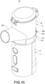
- the nebulizer 10 includes a main body 1, a spraying head 2 and an engagement structure 4.
- the main body 1 includes a body 11, a power assembly 12 received in the body 11 and a first conductive member 13 electrically connected to the power assembly 12.
- the body 11 defines an axial direction d1 and a radial direction d2.
- the power assembly 12 includes a circuit board and a battery
- the first conductive member 13 includes multiple pogo pins, but not limited to these.
- the top of the body 11 is protruded with a block 111.
- the block 111 has a front side 112, a rear side 113, a left side 114, a right side 115 and a top side 116.
- the first conductive member 13 is installed on the front side 112.
- the spraying head 2 includes a spraying seat 21 assembled to (assemblable with) or disassembled from (detachable with) the body 11 along the radial direction d2.
- the bottom and the outer periphery of the spraying seat 21 are formed with a recess 211.
- the recess 211 has an inner bottom 212 and a U-shaped inner sidewall 213 disposed on a side of the inner bottom 212.
- the quick-release nebulizer 10 of the disclosure further includes a sliding rail structure 3.
- the sliding rail structure 3 includes one or more sliders 31 formed on either one of the body 11 and the spraying seat 21 and one or multiple pairs of rails 32 formed on the other one of the body 11 and the spraying seat 21.
- the sliders 31 are two in number, and the rails 32 are two pairs in number, but not limited to these.
- the two sliders 31 are formed by protruding from the left side 114 and the right side 115 of the block 111.
- Two sides of the U-shaped inner sidewall 213 are formed with two rail grooves 214 along the radial direction d2.
- the U-shaped inner sidewall 213 is formed with each pair of rails 32 corresponding to the upper side and the lower side of each rail groove 214 so that each pair of rails 32 is arranged along the radial direction d2 and in a top-and-bottom configuration.
- Each slider 31 is slidable and stopped between each pair of rails 32 so as to make the spraying seat 21 be able to be assembled to or disassembled from the body 11 along the radial direction d2.
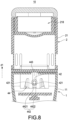
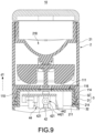
- the spraying head 2 further includes a second conductive member 22 and a no-water detection probe 23.
- the second conductive member 22 is installed on the U-shaped inner sidewall 213 and abuts against the first conductive member 13.
- the power assembly 12 transmits electricity to the no-water detection probe 23 only via the first conductive member 13.
- the second conductive member 22 in the embodiment includes, but not limited to, multiple conductive terminals.
- the spraying head 2 further includes a nebulizing sheet 24 installed at the junction between the nozzle 217 and the agent chamber 218.
- An end of the no-water detection probe 23 stretches in the agent chamber 218 and is arranged corresponding to the nebulizing sheet 24.
- the nebulizing sheet 24 is electrically connected with the second conductive member 22.
- the power assembly 12 transmits electricity to the nebulizing sheet 24 via the first conductive member 13 and the second conductive member 22.
- the no-water detection probe 23 is used to detect if liquid exists after being electrified.
- the nebulizing sheet 24 vibrates after being electrified to nebulize liquid in the agent chamber 218 and allows the nebulized liquid to pass through for being ejected through the nozzle 217.
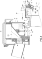
- the engagement structure 4 includes a notch 41 formed on one of the body 11 and the spraying seat 21, a T-shaped trench 42 formed on an inner wall of the notch 41 along the axial direction d1, an engaging trench 43 formed on the other one of the body 11 and the spraying seat 21 and arranged corresponding to the notch 41, and a movable member 44 movably received in the notch 41.
- a side of the movable member 44 is extended with a handle 441 exposed from the notch 41, another side thereof is extended with a T-shaped block 442 slidably received in the T-shaped trench 42, and still another side thereof is protruded with an engaging block 443 along the axial direction d1, which may be embedded in or separated from the engaging trench 43.
- the T-shaped block 442 has a head portion 4421 and a rod portion 4422 connected between the head portion 4421 and the movable member 44.
- the inner wall of the T-shaped trench 42 is extended with two resistant bumps 421 that are frictional with the rod portion 4422.
- the notch 41 of the embodiment is formed by indenting the rear side 113 and the top side 116.
- the notch 41 has an opening 411 formed on the rear side 113 and an inner end face 412 corresponding to the opening 411.
- the T-shaped trench 42 is formed by indenting the inner end face 412 and the top side 116.
- the engaging trench 43 is formed by indenting the inner bottom 212.
- the handle 441 is exposed from the opening 411.
- the rod portion 4422 goes up over the two resistant bumps 421 and rubs the two resistant bumps 421 to transmit a hand-operated resistance. After that, the two resistant bumps 421 abut against the bottom edge of the rod portion 4422 to temporarily lock the position of the movable member 44 until a user downward pushes the handle 441 to move the rod portion 4422 to go down over the two resistant bumps 421 so as to release the position of the movable member 44 to make the engaging block 443 smoothly disengage from the engaging trench 43.
- the spraying seat 21 is assembled to the body 11 through the sliding rail structure 3 along the radial direction d2 first, and then the handle 441 is pushed upward along the axial direction d1 to drive the whole movable member 44 to move upward so as to make the engaging block 443 be embedded in the engaging trench 43 to lock the spraying seat 21.
- the spraying head 2 may be rapidly assembled to the main body 1.
- the handle 441 is pushed downward along the axial direction d1 to drive the whole movable member 44 to move downward so as to make the engaging block 443 disengage from the engaging trench 43 to release the spraying seat 21, and then the spraying seat 21 is removed from the body 11 through the sliding rail structure 3 along the radial direction d2.
- the spraying head 2 may be rapidly disassembled from the main body 1. Therefore, the quick-release nebulizer 10 has the function of conveniently and rapidly assembling and disassembling the spraying head 2.
Landscapes
- Health & Medical Sciences (AREA)
- Engineering & Computer Science (AREA)
- Animal Behavior & Ethology (AREA)
- Anesthesiology (AREA)
- Biomedical Technology (AREA)
- Heart & Thoracic Surgery (AREA)
- Hematology (AREA)
- Life Sciences & Earth Sciences (AREA)
- General Health & Medical Sciences (AREA)
- Public Health (AREA)
- Veterinary Medicine (AREA)
- Pulmonology (AREA)
- Bioinformatics & Cheminformatics (AREA)
- Containers And Packaging Bodies Having A Special Means To Remove Contents (AREA)
Claims (10)
- Zerstäuber, umfassend:einen Hauptkörper (1), der einen Körper (11) umfasst, wobei der Körper (11) eine axiale Richtung (d1) und eine radiale Richtung (d2) definiert;einen Sprühkopf (2), der einen Sprühsitz (21) umfasst, der entlang der radialen Richtung (d2) an den Körper (11) montiert oder von diesem demontiert wird; undeine Eingriffsstruktur (4), umfassend eine Kerbe (41), die an einem von dem Körper (11) und dem Sprühsitz (21) angeordnet ist, einen T-förmigen Graben (42), der an einer Innenwand der Kerbe (41) entlang der axialen Richtung (d1) angeordnet ist, einen Eingriffsgraben (43), der an einem anderen von dem Körper (11) und dem Sprühsitz (21) angeordnet ist und entsprechend der Kerbe (41) angeordnet ist, und ein bewegliches Element (44), das in der Kerbe (41) aufgenommen ist, wobei eine Seite des beweglichen Elements (44) mit einem Griff (441) verlängert ist, der von der Kerbe (41) freiliegt, eine andere Seite des beweglichen Elements (44) mit einem T-förmigen Block (442) verlängert ist, der gleitend in dem T-förmigen Graben (42) aufgenommen ist, und noch eine andere Seite des beweglichen Elements (44) mit einem Eingriffsblock (443) hervorsteht, der in dem Eingriffsgraben (43) eingebettet oder von diesem entlang der axialen Richtung getrennt ist.
- Zerstäuber nach Anspruch 1, wobei der T-förmige Block (442) einen Kopfteil (4421) und einen Stabteil (4422) umfasst, der zwischen dem Kopfteil (4421) und dem beweglichen Element (44) verbunden ist, und eine Innenwand des T-förmigen Grabens (42) mit zwei widerstandsfähigen Höckern (421) verlängert ist, die mit dem Stabteil (4422) reiben.
- Zerstäuber nach Anspruch 2, der ferner eine Gleitschienenstruktur (3) umfasst, wobei die Gleitschienenstruktur (3) mindestens einen Gleiter (31), der entweder am Körper (11) oder am Sprühsitz (21) angeordnet ist, und mindestens ein Paar Schienen (32) umfasst, die am anderen Körper (11) oder am Sprühsitz (21) angeordnet sind, das mindestens eine Paar von Schienen (32) entlang der radialen Richtung (d2) und in einer Oben-Unten-Konfiguration angeordnet ist, und der mindestens eine Schieber (31) zwischen dem mindestens einen Paar von Schienen (32) verschiebbar und arretierbar ist.
- Zerstäuber nach Anspruch 3, wobei eine Oberseite des Körpers (11) mit einem Block (111) hervorsteht, der Block (111) eine Rückseite (113), eine linke Seite (114), eine rechte Seite (115) und eine Oberseite (116) umfasst, der Schieber (31) zwei an der Zahl ist, die beiden Schieber (31) von der linken Seite (114) und der rechten Seite (115) hervorstehen und die Kerbe (41) auf der Rückseite (113) und der Oberseite (116) eingekerbt ist.
- Zerstäuber nach Anspruch 4, wobei die Kerbe (41) eine an der Rückseite (113) definierte Öffnung (411) und eine der Öffnung (411) entsprechende innere Endfläche (412) aufweist, der T-förmige Graben (42) an der inneren Endfläche (412) und der Oberseite (116) eingekerbt ist und der Griff (441) aus der Öffnung (411) herausragt.
- Zerstäuber nach Anspruch 4, wobei ein Boden und ein äußerer Umfang des Sprühsitzes (21) mit einer Aussparung (211) angeordnet sind, wobei die Aussparung (211) einen inneren Boden (212) und eine U-förmige innere Seitenwand (213) umfasst, die an einer Seite des inneren Bodens (212) angeordnet ist, der Eingriffsgraben (43) am inneren Boden (212) eingekerbt ist, und die beiden widerstandsfähigen Höcker (421) an einer Unterkante des Stangenabschnitts (4422) anliegen, wenn der Eingriffsblock (443) in den Eingriffsgraben (43) eingebettet ist.
- Zerstäuber nach Anspruch 6, wobei die Schienen (32) aus zwei Paaren bestehen, zwei Seiten der U-förmigen inneren Seitenwand (213) mit zwei Schienennuten (214) entlang der radialen Richtung (d2) angeordnet sind und jedes Paar von Schienen (32) auf einer oberen Seite und einer unteren Seite jeder Schienennut (214) entsprechend angeordnet ist.
- Zerstäuber nach Anspruch 6, wobei der Block (111) eine Vorderseite (112) aufweist, der Hauptkörper (1) eine in dem Körper (11) aufgenommene Leistungsbaugruppe (12) und ein erstes leitendes Element (13) aufweist, das an der Vorderseite (112) angebracht und mit der Leistungsbaugruppe (12) elektrisch verbunden ist.
- Zerstäuber nach Anspruch 8, wobei eine Außenseite des Sprühsitzes (21) mit einer Düse (217) verlängert ist und eine Innenseite des Sprühsitzes (21) mit einer Wirkstoffkammer (218) angeordnet ist, die mit der Düse (217) in Verbindung steht, und der Sprühkopf (2) ferner ein Zerstäubungsblatt (24) umfasst, das an einer Verbindung zwischen der Düse (217) und der Wirkstoffkammer (218) installiert ist.
- Zerstäuber nach Anspruch 9, wobei der Sprühkopf (2) ferner ein zweites leitendes Element (22) und eine Wasserfreiheitserkennungssonde (23) umfasst, wobei das zweite leitende Element (22) an der U-förmigen inneren Seitenwand (213) installiert ist und an dem ersten leitenden Element (13) anliegt, ein Ende der wasserfreien Erfassungssonde (23) sich in die Wirkstoffkammer (218) erstreckt und entsprechend der Vernebelungsfolie (24) angeordnet ist, und die Vernebelungsfolie (24) elektrisch mit dem zweiten leitfähigen Element (22) verbunden ist.
Priority Applications (1)
| Application Number | Priority Date | Filing Date | Title |
|---|---|---|---|
| EP22176697.5A EP4285970B1 (de) | 2022-06-01 | 2022-06-01 | Schnell abnehmbarer zerstäuber |
Applications Claiming Priority (1)
| Application Number | Priority Date | Filing Date | Title |
|---|---|---|---|
| EP22176697.5A EP4285970B1 (de) | 2022-06-01 | 2022-06-01 | Schnell abnehmbarer zerstäuber |
Publications (3)
| Publication Number | Publication Date |
|---|---|
| EP4285970A1 EP4285970A1 (de) | 2023-12-06 |
| EP4285970C0 EP4285970C0 (de) | 2024-08-28 |
| EP4285970B1 true EP4285970B1 (de) | 2024-08-28 |
Family
ID=81940567
Family Applications (1)
| Application Number | Title | Priority Date | Filing Date |
|---|---|---|---|
| EP22176697.5A Active EP4285970B1 (de) | 2022-06-01 | 2022-06-01 | Schnell abnehmbarer zerstäuber |
Country Status (1)
| Country | Link |
|---|---|
| EP (1) | EP4285970B1 (de) |
Family Cites Families (5)
| Publication number | Priority date | Publication date | Assignee | Title |
|---|---|---|---|---|
| EP3103496B1 (de) * | 2015-06-11 | 2018-08-15 | Delta Electronics, Inc. | Vernebelungssystem |
| JP6686682B2 (ja) * | 2016-05-09 | 2020-04-22 | オムロンヘルスケア株式会社 | メッシュ式ネブライザおよび交換部材 |
| CN109091729B (zh) * | 2017-06-20 | 2021-02-02 | 台达电子工业股份有限公司 | 具有按压式药杯的喷雾器 |
| CN111956917B (zh) * | 2020-08-18 | 2022-04-01 | 深圳市贝格美科技有限公司 | 一种多功能超声波雾化器 |
| TWI761074B (zh) * | 2021-02-09 | 2022-04-11 | 心誠鎂行動醫電股份有限公司 | 霧化器 |
-
2022
- 2022-06-01 EP EP22176697.5A patent/EP4285970B1/de active Active
Also Published As
| Publication number | Publication date |
|---|---|
| EP4285970C0 (de) | 2024-08-28 |
| EP4285970A1 (de) | 2023-12-06 |
Similar Documents
| Publication | Publication Date | Title |
|---|---|---|
| US12374843B2 (en) | Pogo pin connector | |
| US12263297B2 (en) | Quick-release nebulizer | |
| US10105511B2 (en) | Respiratory humidifier | |
| US12491041B2 (en) | Medical device and storage box for medical article | |
| JP7776635B2 (ja) | エアロゾル発生装置 | |
| US8113849B2 (en) | Docking system for use with a mobile medication cart | |
| JP2004538072A (ja) | ガイドタブ及びガイドタブを組み込んだスライド | |
| TWI642454B (zh) | 具有按壓式藥杯的噴霧器 | |
| EP4285970A1 (de) | Schnell abnehmbarer zerstäuber | |
| CN117180564B (zh) | 一种带锁定机构的计数器和包含计数器的喷雾器 | |
| CN220090199U (zh) | 一种用于呼吸机的水箱及呼吸机 | |
| CN218219138U (zh) | 便于拆卸的雾化器及雾化设备 | |
| CN214505324U (zh) | 电子笔按键组件及电子笔 | |
| CN116370779B (zh) | 一种用于呼吸机的水箱及呼吸机 | |
| CN221106642U (zh) | 一种下壳组件及雾化装置 | |
| CN217409482U (zh) | 快拆式雾化器 | |
| US8619032B2 (en) | Mouse structure with retracting function | |
| TWM630765U (zh) | 快拆式霧化器 | |
| CN216568350U (zh) | 一种雾化器 | |
| CN220000751U (zh) | 进气组件和电子雾化装置 | |
| CN221556676U (zh) | 可拆装式按摩器 | |
| CN209807149U (zh) | 一种电子烟 | |
| CN220365825U (zh) | 适用于内窥镜传动装置的隔离板卡扣解锁机构 | |
| CN222507878U (zh) | 一种电池盖板锁合结构及遥测监护设备 | |
| CN223787155U (zh) | 加热基座和雾化设备 |
Legal Events
| Date | Code | Title | Description |
|---|---|---|---|
| PUAI | Public reference made under article 153(3) epc to a published international application that has entered the european phase |
Free format text: ORIGINAL CODE: 0009012 |
|
| STAA | Information on the status of an ep patent application or granted ep patent |
Free format text: STATUS: REQUEST FOR EXAMINATION WAS MADE |
|
| 17P | Request for examination filed |
Effective date: 20230108 |
|
| AK | Designated contracting states |
Kind code of ref document: A1 Designated state(s): AL AT BE BG CH CY CZ DE DK EE ES FI FR GB GR HR HU IE IS IT LI LT LU LV MC MK MT NL NO PL PT RO RS SE SI SK SM TR |
|
| GRAP | Despatch of communication of intention to grant a patent |
Free format text: ORIGINAL CODE: EPIDOSNIGR1 |
|
| STAA | Information on the status of an ep patent application or granted ep patent |
Free format text: STATUS: GRANT OF PATENT IS INTENDED |
|
| GRAS | Grant fee paid |
Free format text: ORIGINAL CODE: EPIDOSNIGR3 |
|
| RIC1 | Information provided on ipc code assigned before grant |
Ipc: A61M 15/00 20060101ALI20240228BHEP Ipc: A61M 11/00 20060101AFI20240228BHEP |
|
| INTG | Intention to grant announced |
Effective date: 20240315 |
|
| GRAA | (expected) grant |
Free format text: ORIGINAL CODE: 0009210 |
|
| STAA | Information on the status of an ep patent application or granted ep patent |
Free format text: STATUS: THE PATENT HAS BEEN GRANTED |
|
| AK | Designated contracting states |
Kind code of ref document: B1 Designated state(s): AL AT BE BG CH CY CZ DE DK EE ES FI FR GB GR HR HU IE IS IT LI LT LU LV MC MK MT NL NO PL PT RO RS SE SI SK SM TR |
|
| REG | Reference to a national code |
Ref country code: CH Ref legal event code: EP |
|
| REG | Reference to a national code |
Ref country code: DE Ref legal event code: R096 Ref document number: 602022005602 Country of ref document: DE |
|
| REG | Reference to a national code |
Ref country code: IE Ref legal event code: FG4D |
|
| U01 | Request for unitary effect filed |
Effective date: 20240828 |
|
| U07 | Unitary effect registered |
Designated state(s): AT BE BG DE DK EE FI FR IT LT LU LV MT NL PT RO SE SI Effective date: 20240905 |
|
| PG25 | Lapsed in a contracting state [announced via postgrant information from national office to epo] |
Ref country code: NO Free format text: LAPSE BECAUSE OF FAILURE TO SUBMIT A TRANSLATION OF THE DESCRIPTION OR TO PAY THE FEE WITHIN THE PRESCRIBED TIME-LIMIT Effective date: 20241128 |
|
| PG25 | Lapsed in a contracting state [announced via postgrant information from national office to epo] |
Ref country code: GR Free format text: LAPSE BECAUSE OF FAILURE TO SUBMIT A TRANSLATION OF THE DESCRIPTION OR TO PAY THE FEE WITHIN THE PRESCRIBED TIME-LIMIT Effective date: 20241129 Ref country code: PL Free format text: LAPSE BECAUSE OF FAILURE TO SUBMIT A TRANSLATION OF THE DESCRIPTION OR TO PAY THE FEE WITHIN THE PRESCRIBED TIME-LIMIT Effective date: 20240828 |
|
| PG25 | Lapsed in a contracting state [announced via postgrant information from national office to epo] |
Ref country code: IS Free format text: LAPSE BECAUSE OF FAILURE TO SUBMIT A TRANSLATION OF THE DESCRIPTION OR TO PAY THE FEE WITHIN THE PRESCRIBED TIME-LIMIT Effective date: 20241228 |
|
| PG25 | Lapsed in a contracting state [announced via postgrant information from national office to epo] |
Ref country code: HR Free format text: LAPSE BECAUSE OF FAILURE TO SUBMIT A TRANSLATION OF THE DESCRIPTION OR TO PAY THE FEE WITHIN THE PRESCRIBED TIME-LIMIT Effective date: 20240828 |
|
| PG25 | Lapsed in a contracting state [announced via postgrant information from national office to epo] |
Ref country code: RS Free format text: LAPSE BECAUSE OF FAILURE TO SUBMIT A TRANSLATION OF THE DESCRIPTION OR TO PAY THE FEE WITHIN THE PRESCRIBED TIME-LIMIT Effective date: 20241128 Ref country code: ES Free format text: LAPSE BECAUSE OF FAILURE TO SUBMIT A TRANSLATION OF THE DESCRIPTION OR TO PAY THE FEE WITHIN THE PRESCRIBED TIME-LIMIT Effective date: 20240828 |
|
| PG25 | Lapsed in a contracting state [announced via postgrant information from national office to epo] |
Ref country code: RS Free format text: LAPSE BECAUSE OF FAILURE TO SUBMIT A TRANSLATION OF THE DESCRIPTION OR TO PAY THE FEE WITHIN THE PRESCRIBED TIME-LIMIT Effective date: 20241128 Ref country code: PL Free format text: LAPSE BECAUSE OF FAILURE TO SUBMIT A TRANSLATION OF THE DESCRIPTION OR TO PAY THE FEE WITHIN THE PRESCRIBED TIME-LIMIT Effective date: 20240828 Ref country code: NO Free format text: LAPSE BECAUSE OF FAILURE TO SUBMIT A TRANSLATION OF THE DESCRIPTION OR TO PAY THE FEE WITHIN THE PRESCRIBED TIME-LIMIT Effective date: 20241128 Ref country code: IS Free format text: LAPSE BECAUSE OF FAILURE TO SUBMIT A TRANSLATION OF THE DESCRIPTION OR TO PAY THE FEE WITHIN THE PRESCRIBED TIME-LIMIT Effective date: 20241228 Ref country code: HR Free format text: LAPSE BECAUSE OF FAILURE TO SUBMIT A TRANSLATION OF THE DESCRIPTION OR TO PAY THE FEE WITHIN THE PRESCRIBED TIME-LIMIT Effective date: 20240828 Ref country code: GR Free format text: LAPSE BECAUSE OF FAILURE TO SUBMIT A TRANSLATION OF THE DESCRIPTION OR TO PAY THE FEE WITHIN THE PRESCRIBED TIME-LIMIT Effective date: 20241129 Ref country code: ES Free format text: LAPSE BECAUSE OF FAILURE TO SUBMIT A TRANSLATION OF THE DESCRIPTION OR TO PAY THE FEE WITHIN THE PRESCRIBED TIME-LIMIT Effective date: 20240828 |
|
| PG25 | Lapsed in a contracting state [announced via postgrant information from national office to epo] |
Ref country code: SM Free format text: LAPSE BECAUSE OF FAILURE TO SUBMIT A TRANSLATION OF THE DESCRIPTION OR TO PAY THE FEE WITHIN THE PRESCRIBED TIME-LIMIT Effective date: 20240828 |
|
| PG25 | Lapsed in a contracting state [announced via postgrant information from national office to epo] |
Ref country code: CZ Free format text: LAPSE BECAUSE OF FAILURE TO SUBMIT A TRANSLATION OF THE DESCRIPTION OR TO PAY THE FEE WITHIN THE PRESCRIBED TIME-LIMIT Effective date: 20240828 |
|
| PG25 | Lapsed in a contracting state [announced via postgrant information from national office to epo] |
Ref country code: SK Free format text: LAPSE BECAUSE OF FAILURE TO SUBMIT A TRANSLATION OF THE DESCRIPTION OR TO PAY THE FEE WITHIN THE PRESCRIBED TIME-LIMIT Effective date: 20240828 |
|
| PLBE | No opposition filed within time limit |
Free format text: ORIGINAL CODE: 0009261 |
|
| STAA | Information on the status of an ep patent application or granted ep patent |
Free format text: STATUS: NO OPPOSITION FILED WITHIN TIME LIMIT |
|
| 26N | No opposition filed |
Effective date: 20250530 |
|
| U20 | Renewal fee for the european patent with unitary effect paid |
Year of fee payment: 4 Effective date: 20250630 |
|
| REG | Reference to a national code |
Ref country code: CH Ref legal event code: H13 Free format text: ST27 STATUS EVENT CODE: U-0-0-H10-H13 (AS PROVIDED BY THE NATIONAL OFFICE) Effective date: 20260127 |
|
| PG25 | Lapsed in a contracting state [announced via postgrant information from national office to epo] |
Ref country code: MC Free format text: LAPSE BECAUSE OF FAILURE TO SUBMIT A TRANSLATION OF THE DESCRIPTION OR TO PAY THE FEE WITHIN THE PRESCRIBED TIME-LIMIT Effective date: 20240828 |
|
| PG25 | Lapsed in a contracting state [announced via postgrant information from national office to epo] |
Ref country code: IE Free format text: LAPSE BECAUSE OF NON-PAYMENT OF DUE FEES Effective date: 20250601 |
|
| PG25 | Lapsed in a contracting state [announced via postgrant information from national office to epo] |
Ref country code: CH Free format text: LAPSE BECAUSE OF NON-PAYMENT OF DUE FEES Effective date: 20250630 |