EP4285035B1 - Rolling bearing arrangement and method for producing a pocket cage - Google Patents
Rolling bearing arrangement and method for producing a pocket cage Download PDFInfo
- Publication number
- EP4285035B1 EP4285035B1 EP21823744.4A EP21823744A EP4285035B1 EP 4285035 B1 EP4285035 B1 EP 4285035B1 EP 21823744 A EP21823744 A EP 21823744A EP 4285035 B1 EP4285035 B1 EP 4285035B1
- Authority
- EP
- European Patent Office
- Prior art keywords
- cage
- axial
- grooves
- rolling bearing
- Prior art date
- Legal status (The legal status is an assumption and is not a legal conclusion. Google has not performed a legal analysis and makes no representation as to the accuracy of the status listed.)
- Active
Links
Images


Classifications
-
- F—MECHANICAL ENGINEERING; LIGHTING; HEATING; WEAPONS; BLASTING
- F16—ENGINEERING ELEMENTS AND UNITS; GENERAL MEASURES FOR PRODUCING AND MAINTAINING EFFECTIVE FUNCTIONING OF MACHINES OR INSTALLATIONS; THERMAL INSULATION IN GENERAL
- F16C—SHAFTS; FLEXIBLE SHAFTS; ELEMENTS OR CRANKSHAFT MECHANISMS; ROTARY BODIES OTHER THAN GEARING ELEMENTS; BEARINGS
- F16C33/00—Parts of bearings; Special methods for making bearings or parts thereof
- F16C33/30—Parts of ball or roller bearings
- F16C33/46—Cages for rollers or needles
- F16C33/4617—Massive or moulded cages having cage pockets surrounding the rollers, e.g. machined window cages
- F16C33/4623—Massive or moulded cages having cage pockets surrounding the rollers, e.g. machined window cages formed as one-piece cages, i.e. monoblock cages
- F16C33/4629—Massive or moulded cages having cage pockets surrounding the rollers, e.g. machined window cages formed as one-piece cages, i.e. monoblock cages made from metal, e.g. cast or machined window cages
-
- F—MECHANICAL ENGINEERING; LIGHTING; HEATING; WEAPONS; BLASTING
- F16—ENGINEERING ELEMENTS AND UNITS; GENERAL MEASURES FOR PRODUCING AND MAINTAINING EFFECTIVE FUNCTIONING OF MACHINES OR INSTALLATIONS; THERMAL INSULATION IN GENERAL
- F16C—SHAFTS; FLEXIBLE SHAFTS; ELEMENTS OR CRANKSHAFT MECHANISMS; ROTARY BODIES OTHER THAN GEARING ELEMENTS; BEARINGS
- F16C33/00—Parts of bearings; Special methods for making bearings or parts thereof
- F16C33/30—Parts of ball or roller bearings
- F16C33/46—Cages for rollers or needles
- F16C33/467—Details of individual pockets, e.g. shape or roller retaining means
- F16C33/4676—Details of individual pockets, e.g. shape or roller retaining means of the stays separating adjacent cage pockets, e.g. guide means for the bearing-surface of the rollers
-
- F—MECHANICAL ENGINEERING; LIGHTING; HEATING; WEAPONS; BLASTING
- F16—ENGINEERING ELEMENTS AND UNITS; GENERAL MEASURES FOR PRODUCING AND MAINTAINING EFFECTIVE FUNCTIONING OF MACHINES OR INSTALLATIONS; THERMAL INSULATION IN GENERAL
- F16C—SHAFTS; FLEXIBLE SHAFTS; ELEMENTS OR CRANKSHAFT MECHANISMS; ROTARY BODIES OTHER THAN GEARING ELEMENTS; BEARINGS
- F16C33/00—Parts of bearings; Special methods for making bearings or parts thereof
- F16C33/30—Parts of ball or roller bearings
- F16C33/66—Special parts or details in view of lubrication
- F16C33/6603—Special parts or details in view of lubrication with grease as lubricant
- F16C33/6607—Retaining the grease in or near the bearing
- F16C33/6614—Retaining the grease in or near the bearing in recesses or cavities provided in retainers, races or rolling elements
-
- F—MECHANICAL ENGINEERING; LIGHTING; HEATING; WEAPONS; BLASTING
- F16—ENGINEERING ELEMENTS AND UNITS; GENERAL MEASURES FOR PRODUCING AND MAINTAINING EFFECTIVE FUNCTIONING OF MACHINES OR INSTALLATIONS; THERMAL INSULATION IN GENERAL
- F16C—SHAFTS; FLEXIBLE SHAFTS; ELEMENTS OR CRANKSHAFT MECHANISMS; ROTARY BODIES OTHER THAN GEARING ELEMENTS; BEARINGS
- F16C33/00—Parts of bearings; Special methods for making bearings or parts thereof
- F16C33/30—Parts of ball or roller bearings
- F16C33/66—Special parts or details in view of lubrication
- F16C33/6637—Special parts or details in view of lubrication with liquid lubricant
- F16C33/664—Retaining the liquid in or near the bearing
- F16C33/6651—Retaining the liquid in or near the bearing in recesses or cavities provided in retainers, races or rolling elements
-
- F—MECHANICAL ENGINEERING; LIGHTING; HEATING; WEAPONS; BLASTING
- F16—ENGINEERING ELEMENTS AND UNITS; GENERAL MEASURES FOR PRODUCING AND MAINTAINING EFFECTIVE FUNCTIONING OF MACHINES OR INSTALLATIONS; THERMAL INSULATION IN GENERAL
- F16C—SHAFTS; FLEXIBLE SHAFTS; ELEMENTS OR CRANKSHAFT MECHANISMS; ROTARY BODIES OTHER THAN GEARING ELEMENTS; BEARINGS
- F16C19/00—Bearings with rolling contact, for exclusively rotary movement
- F16C19/22—Bearings with rolling contact, for exclusively rotary movement with bearing rollers essentially of the same size in one or more circular rows, e.g. needle bearings
- F16C19/44—Needle bearings
- F16C19/46—Needle bearings with one row or needles
- F16C19/466—Needle bearings with one row or needles comprising needle rollers and an outer ring, i.e. subunit without inner ring
-
- F—MECHANICAL ENGINEERING; LIGHTING; HEATING; WEAPONS; BLASTING
- F16—ENGINEERING ELEMENTS AND UNITS; GENERAL MEASURES FOR PRODUCING AND MAINTAINING EFFECTIVE FUNCTIONING OF MACHINES OR INSTALLATIONS; THERMAL INSULATION IN GENERAL
- F16C—SHAFTS; FLEXIBLE SHAFTS; ELEMENTS OR CRANKSHAFT MECHANISMS; ROTARY BODIES OTHER THAN GEARING ELEMENTS; BEARINGS
- F16C2220/00—Shaping
- F16C2220/80—Shaping by separating parts, e.g. by severing, cracking
- F16C2220/84—Shaping by separating parts, e.g. by severing, cracking by perforating; by punching; by stamping-out
-
- F—MECHANICAL ENGINEERING; LIGHTING; HEATING; WEAPONS; BLASTING
- F16—ENGINEERING ELEMENTS AND UNITS; GENERAL MEASURES FOR PRODUCING AND MAINTAINING EFFECTIVE FUNCTIONING OF MACHINES OR INSTALLATIONS; THERMAL INSULATION IN GENERAL
- F16C—SHAFTS; FLEXIBLE SHAFTS; ELEMENTS OR CRANKSHAFT MECHANISMS; ROTARY BODIES OTHER THAN GEARING ELEMENTS; BEARINGS
- F16C2300/00—Application independent of particular apparatuses
- F16C2300/02—General use or purpose, i.e. no use, purpose, special adaptation or modification indicated or a wide variety of uses mentioned
Definitions
- the invention relates to a rolling bearing arrangement comprising a rolling bearing with an inner ring, an outer ring, rolling elements and a cage, wherein the inner ring has an inner ring raceway and the outer ring has an outer ring raceway, wherein the rolling elements are arranged rotatably between the inner ring and the outer ring in the cage at a distance from one another, wherein the rolling elements roll on the inner ring raceway and the outer ring raceway, wherein the rolling elements are designed as rolling element rollers and the cage is designed as a pocket cage having two coaxially arranged pocket cage rings which are connected to a plurality of pocket cage axial separating webs to form pocket openings for receiving the rolling elements.
- the invention further relates to a method for producing a pocket cage.
- Rolling bearings with cage-guided rolling elements are well known from the state of the art. Examples of such cages include the publications JP H05 118337 A , JP 2000 352 423 A , DE 16 94 407 U or DE 696 27 937 T2 They can be used, in particular, to enable rotary movements with the lowest possible friction losses. Rolling bearings can be used, in particular, for the fixation and/or support of axles and shafts. Depending on their design, they absorb radial and/or axial forces while simultaneously enabling the rotation of the shaft or the components mounted on an axle.
- rolling elements are arranged between an inner ring and an outer ring of the rolling bearing. Between these three main components Within the rolling bearing, rolling friction typically occurs primarily between the inner ring, outer ring, and rolling elements. Since the rolling elements in the inner and outer rings can roll preferentially on hardened steel surfaces with optimized lubrication, the rolling friction of such bearings is relatively low.
- DE 10 2007 046131 B3 discloses a method for producing a pocket cage for a rolling bearing, comprising the steps of providing a cylinder sleeve with an inner circumferential surface, placing the cylinder sleeve on a shaft so that the inner circumferential surface bears against the shaft, and punching out pocket openings from the cylinder sleeve so that a pocket cage is formed.
- the object of the invention is to provide a rolling bearing having a cage with a manufacturing-optimized design, in particular, one that is optimized for a stamping process. Furthermore, the object of the invention is to provide an optimized method for producing a cage for a rolling bearing.
- this design of the pocket cage axial separators is particularly suitable for the production of the pocket cage in high-speed punching processes, in which high shear forces can occur when punching out the pocket openings, which is particularly important for designs, that deviate from the one proposed here can lead to undesirable plastic deformations at the pocket cage axial separators.
- This is particularly critical for cage designs that have internal grooves on the pocket cage axial separators, which are provided, for example, for guiding lubricant within the rolling bearing.
- the design according to the invention makes it possible to provide a cage that has the grooves necessary for guiding lubricant between the rolling element and the cage and, at the same time, can be manufactured particularly economically and reliably.
- a rolling bearing can be single-row or multi-row.
- the inner ring can, in particular, connect the shaft accommodating the rolling bearing to the rolling bearing or the rolling elements.
- the outer surface of the shaft can be connected to the inner surface of the inner ring, with the rolling elements of the rolling bearing rolling on the inner ring raceway opposite this surface.
- the inner ring can be made of a metallic and/or ceramic material. It is generally conceivable for the inner ring to be constructed in one or more parts, particularly in two parts.
- the outer ring can, in particular, connect the bearing support surrounding the rolling bearing to the rolling bearing or the rolling elements.
- the side of the bearing support facing the rolling bearing can be connected to the outer surface of the outer ring, with the rolling elements of the rolling bearing rolling on the outer ring raceway opposite this surface.
- the outer ring can be made of a metallic and/or ceramic material. It is generally conceivable for the outer ring to be constructed in one or more parts, particularly in two parts.
- the rolling elements are shaped like a roller. They roll along the raceways of the bearing and are responsible for transferring the force acting on a radial rolling bearing from the outer ring to the inner ring and vice versa. Roller-shaped rolling elements are also referred to as roller rolling elements, and spherical rolling elements are referred to as bearing balls. Roller-shaped rolling elements can be selected, for example, from the group of symmetrical spherical rollers, asymmetrical spherical rollers, cylindrical rollers, needle rollers, and/or tapered rollers.
- the rolling elements are designed as needle rollers.
- a rolling bearing assembly has a cage designed as a pocket cage that guides the rolling elements.
- the cage is designed to space the rolling element rollers apart from one another, for example, to minimize friction and heat generation of the rolling elements. Furthermore, the cage keeps the roller rolling elements at a fixed distance from one another during rolling, thereby achieving an even load distribution.
- the cage can preferably be made in one piece, but can also be made in several pieces.
- the rolling elements can roll within the rolling bearing, particularly on the inner raceway of the inner ring.
- the surface of the inner raceway can advantageously be designed to be abrasion-resistant, for example, by means of an appropriate surface treatment process and/or by applying an appropriate additional material layer.
- the inner ring raceway can be flat or profiled.
- a profiled design of the inner ring raceway can, for example, serve to guide the rolling elements on the inner ring raceway.
- a flat design of the inner ring raceway can, for example, allow a certain axial displacement of the rolling elements on the inner ring raceway.
- the rolling elements can roll within the rolling bearing, particularly on the outer raceway of the outer ring.
- the surface of the outer ring raceway can advantageously be designed to be abrasion-resistant, for example, by means of an appropriate surface treatment process and/or by applying an appropriate additional material layer.
- the outer ring raceway can be flat or profiled.
- a profiled outer ring raceway can, for example, serve to guide the rolling elements on the outer ring raceway.
- a flat outer ring raceway on the other hand, can allow a certain degree of axial displacement of the rolling elements on the outer ring raceway.
- the central contact surface may be arranged centrally on the pocket cage axial separators relative to their axial extent, so that shear forces acting on the pocket cage axial separators during production are distributed as evenly as possible in the axial extent across the pocket cage axial separators. Furthermore, the central arrangement provides a support point in the pocket cage axial separators where the greatest bending stresses can typically occur in the pocket cage axial separators during punching of the pocket openings.
- the grooves may further be advantageous for the grooves to each have an opening width of between 2% and 15% of the axial extent of the pocket cage axial separating webs, so that a sufficiently large support and contact surface can be provided when punching out the pocket openings during the manufacturing process of the cage.
- the grooves may further be preferred that the grooves have an identical opening width, which is advantageous in terms of symmetrical stress distribution in the pocket cage axial separators during the manufacturing process has proven to be advantageous.
- the grooves can be advantageous for the grooves to have different axial cross-sectional contours, allowing the lubricant fill volume to be individually adjusted for each groove.
- the grooves it is also possible, and advantageous from a manufacturing perspective, for the grooves to have identical axial cross-sectional contours.
- the axial section contour of at least one of the grooves preferably all grooves, has a circular shape.
- the axial section contour of at least one of the grooves may be advantageous for the axial section contour of at least one of the grooves, preferably all of the grooves, to have a circular arc section, an extension section adjoining the circular arc section and running plane-parallel to the contact surface, and a ramp section adjoining the extension section.
- the radial extent of the pocket cage axial separating webs be identical.
- the pocket cage rings have a radial extent that corresponds to the radial extent of the pocket cage axial separating webs.
- the object of the invention is achieved by a method for producing a pocket cage for a rolling bearing, comprising the steps listed in claim 1.
- the shaft may have at least four punching pockets distributed over its circumference, into which a punching tool can engage to form a cage pocket, thereby enabling a particularly short production time for the pocket cage.
- Figure 1 shows a rolling bearing arrangement 1, comprising a rolling bearing 2 with an inner ring 3, an outer ring 4, rolling elements 5 and a cage Figure 6 .
- the inner ring 3 has an inner ring raceway 7 and the outer ring 4 has an outer ring raceway 8, wherein the rolling elements 5 are rotatably mounted in the cage between the inner ring 3 and the outer ring 4.
- Figure 6 are arranged at a distance from one another.
- the rolling elements 5 roll on the inner ring raceway 7 and the outer ring raceway 8 and, in the embodiment shown, are designed as rolling element rollers 9.
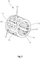
- the Kä Figure 6 configured as a pocket cage 10 formed from a metallic material, which in the Figure 2 is shown.
- the pocket cage 10 has two coaxially arranged identical pocket cage rings 11, which are connected to a plurality of pocket cage axial separators 12 to form pocket openings 13 for receiving the rolling elements 5.
- the pocket cage rings 11 and the pocket cage axial separators 12 are formed monolithically with one another.
- a first embodiment of the pocket cage axial separators 12 is shown in Figure 3 and is explained in more detail below.
- the pocket cage axial separators 12 have on the radially inward facing side a substantially flat contact surface 14, each with two grooves 15 running in the circumferential direction of the pocket cage 10.
- the central contact surface 16, which is formed between the two grooves 15, has an axial extent that corresponds to 3% to 40% of the axial extent of one of the pocket cage axial separators 12.
- a waist 31 is formed on each of the pocket cage axial separators 12 on both sides of the pocket cage axial separators 12 in order to not only guide lubricant through the waist 31 but also, in particular, to provide a spring-elastic effect and/or tension control in the pocket cage axial separators 12.
- the central contact surface 16 is arranged centrally on the pocket cage axial separating webs 12 with respect to the axial extent of the latter. This is shown in the Figure 2 by the central axis of the pocket cage axial separator 12, indicated by a dash-dot line. The mirror-symmetrical design of the pocket cage axial separator 12 along this central axis is clearly visible.
- the grooves 15 also have identical opening widths 17 between 2% and 15% of the axial extent of the pocket cage axial separating webs 12.
- the axial section contour 18 of each of the grooves 15 has a circular shape in the embodiment shown.
- Figure 4 shows one of the Figure 3 different design of the axial section contours 18 of the grooves 15.
- the axial section contour 18 of the grooves 15 according to the embodiment of the Figure 3 has a circular arc section 19, an extension section 20 adjoining the circular arc section 19 and running plane-parallel to the contact surface 14, and a ramp section 21 adjoining the extension section 20.
- the ramp sections 21 of two axially adjacent grooves 15 are aligned toward each other.
- the grooves 15 have identical opening widths 17 between 2-15% of the axial extension of the pocket cage axial separating webs 12.
- a method 22 for producing a pocket cage 10 for a rolling bearing 2 is described with reference to Figures 5 to 9 explained in more detail:
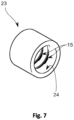
- a metallic cylinder sleeve 23 with an inner surface 24 is provided, as shown in the Figure 5
- the inner circumferential surface 24 of the semi-finished product is the later radially inner contact surface 14 of the pocket cage 10.
- the wall thickness of the cylindrical sleeve 23 corresponds to the later radial extent of the pocket cage axial separators 12 and the pocket cage rings 11.
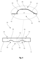
- a process step b) two grooves 15 are introduced into the inner surface 24 of the cylinder sleeve 23, which is shown in the Figure 6 is shown.
- the grooves 15 are formed by means of a grooving tool 30, which is pressed radially from the inside outward against the inner circumferential surface 24.
- the shaping geometries of the grooving tool 30 have an outer contour that corresponds to the later axial section contour 18 of the grooves 15.
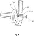
- the cylinder sleeve 23 prepared in this way is then placed onto a shaft 25 in a process step c) so that the inner circumferential surface 24 rests against the shaft 25.
- the pocket openings 13 are punched out of the cylinder sleeve 23 so that a pocket cage 10 is formed, as shown in the Figures 2 to 4 is shown.
- the punching tool 28 lowers toward the shaft 25 and punches out a corresponding pocket opening 13 from the cylinder sleeve 10.
- the shaft 25 can be rotated via the shaft drive 26, wherein the shaft drive 26 preferably comprises a stepper motor.
- the shaft 25, which can also be referred to as a die has at least four punching pockets distributed over its circumference, into which the punching tool 28 can engage to form a pocket opening 13.
- the cylindrical sleeve 23 can enable punching on a punching machine, such as an XAV machine, in particular thanks to the central contact surface 16 of the pocket cage axial separators 12, which is designed as a support surface. Due to the two axially spaced grooves 15, the central contact surface 16 thus remains a support surface for supporting a pocket cage axial separator 12 during punching.
Landscapes
- Engineering & Computer Science (AREA)
- General Engineering & Computer Science (AREA)
- Mechanical Engineering (AREA)
- Rolling Contact Bearings (AREA)
Description
Die Erfindung betrifft eine Wälzlageranordnung, umfassend ein Wälzlager mit einem Innenring, einem Außenring, Wälzkörpern und einem Käfig, wobei der Innenring eine Innenringlaufbahn aufweist und der Außenring eine Außenringlaufbahn aufweist, wobei die Wälzkörper zwischen Innenring und Außenring drehbar in dem Käfig voneinander beabstandet angeordnet sind, wobei die Wälzkörper auf der Innenringlaufbahn und der Außenringlaufbahn wälzen, wobei die Wälzkörper als Wälzkörperrollen ausgebildet sind und der Käfig als Taschenkäfig ausgebildet ist, der zwei koaxial angeordneten Taschenkäfigringe aufweist, welche mit einer Mehrzahl von Taschenkäfigaxialtrennstegen unter Bildung von Taschenöffnungen zur Aufnahme der Wälzkörper verbunden sind. Die Erfindung betrifft ferner ein Verfahren zur Herstellung eines Taschenkäfigs.The invention relates to a rolling bearing arrangement comprising a rolling bearing with an inner ring, an outer ring, rolling elements and a cage, wherein the inner ring has an inner ring raceway and the outer ring has an outer ring raceway, wherein the rolling elements are arranged rotatably between the inner ring and the outer ring in the cage at a distance from one another, wherein the rolling elements roll on the inner ring raceway and the outer ring raceway, wherein the rolling elements are designed as rolling element rollers and the cage is designed as a pocket cage having two coaxially arranged pocket cage rings which are connected to a plurality of pocket cage axial separating webs to form pocket openings for receiving the rolling elements. The invention further relates to a method for producing a pocket cage.
Wälzlager mit käfiggeführten Wälzkörpern sind hinlänglich aus dem Stand der Technik bekannt. Beispielhaft insbesondere für entsprechende Käfige seien die Druckschriften
Hierzu sind zwischen einem Innenring und einem Außenring des Wälzlagers abrollende Wälzkörper angeordnet. Zwischen diesen drei Hauptkomponenten Innenring, Außenring und den Wälzkörpern tritt innerhalb des Wälzlagers in der Regel hauptsächlich Rollreibung auf. Da die Wälzkörper im Innen- und Außenring bevorzugt auf gehärteten Stahlflächen mit optimierter Schmierung abrollen können, ist die Rollreibung derartiger Lager relativ gering.For this purpose, rolling elements are arranged between an inner ring and an outer ring of the rolling bearing. Between these three main components Within the rolling bearing, rolling friction typically occurs primarily between the inner ring, outer ring, and rolling elements. Since the rolling elements in the inner and outer rings can roll preferentially on hardened steel surfaces with optimized lubrication, the rolling friction of such bearings is relatively low.
Die als nächstkommend angesehene
Es besteht ein anhaltendes Bedürfnis daran, Wälzlager kostengünstig und mit hohen Losgrößen fertigen zu können.There is a continuing need to be able to produce rolling bearings cost-effectively and in large batch sizes.
Somit ist es die Aufgabe der Erfindung ein Wälzlager bereitzustellen, das einen Käfig aufweist, welcher eine fertigungstechnisch optimierte Ausgestaltung aufweist, insbesondere für einen Stanzprozess optimiert konstruiert ist. Es ist ferner die Aufgabe der Erfindung, ein optimiertes Verfahren zur Herstellung eines Käfigs für ein Wälzlager bereitzustellen.Thus, the object of the invention is to provide a rolling bearing having a cage with a manufacturing-optimized design, in particular, one that is optimized for a stamping process. Furthermore, the object of the invention is to provide an optimized method for producing a cage for a rolling bearing.
Diese Aufgabe wird gelöst durch eine Wälzlageranordnung mit den in Anspruch 3 aufgeführten Merkmalen.This object is achieved by a rolling bearing arrangement having the features listed in
Der Vorteil dieser Ausgestaltung liegt darin begründet, dass diese Ausgestaltung der Taschenkäfigaxialtrennstege besonders geeignet ist zur Fertigung des Taschenkäfigs in Hochgeschwindigkeitsstanzprozessen, bei denen hohe Scherkräfte beim Ausstanzen der Taschenöffnungen auftreten können, was bei Konstruktionen, die von der hier vorgeschlagenen abweichen, zu unerwünschten plastischen Verformungen an den Taschenkäfigaxialtrennstegen führen kann. Dies ist insbesondere kritisch bei Käfigkonstruktionen, welche innenliegende Nuten an den Taschenkäfigaxialtrennstegen aufweisen, welche beispielsweise zur Schmiermittelführung innerhalb des Wälzlagers vorhanden sind. Mit der erfindungsgemäßen Ausgestaltung kann ein Käfig bereitgestellt werden, der die zur Schmierstoffführung zwischen Wälzkörper und Käfig notwendigen Nuten aufweist und sich gleichzeitig besonders ökonomisch und sicher fertigen lässt.The advantage of this design is that this design of the pocket cage axial separators is particularly suitable for the production of the pocket cage in high-speed punching processes, in which high shear forces can occur when punching out the pocket openings, which is particularly important for designs, that deviate from the one proposed here can lead to undesirable plastic deformations at the pocket cage axial separators. This is particularly critical for cage designs that have internal grooves on the pocket cage axial separators, which are provided, for example, for guiding lubricant within the rolling bearing. The design according to the invention makes it possible to provide a cage that has the grooves necessary for guiding lubricant between the rolling element and the cage and, at the same time, can be manufactured particularly economically and reliably.
Zunächst werden die einzelnen Elemente des beanspruchten Erfindungsgegenstandes in der Reihenfolge ihrer Nennung im Anspruchssatz erläutert und nachfolgend besonders bevorzugte Ausgestaltungen des Erfindungsgegenstandes beschrieben.First, the individual elements of the claimed subject matter of the invention are explained in the order in which they appear in the set of claims, and subsequently, particularly preferred embodiments of the subject matter of the invention are described.
Ein Wälzlager kann ein- oder mehrreihig ausgebildet sein.A rolling bearing can be single-row or multi-row.
Der Innenring kann insbesondere die das Wälzlager aufnehmende Welle mit dem Wälzlager bzw. den Wälzkörpern verbinden. Dabei kann insbesondere die äußere Mantelfläche der Welle mit der inneren Mantelfläche des Innenrings verbunden sein, wobei auf der dieser Mantelfläche gegenüberliegenden Innenringlaufbahn die Wälzkörper des Wälzlagers wälzen. Der Innenring kann aus einem metallischen und/oder keramischen Werkstoff gebildet sein. Es ist grundsätzlich denkbar, den Innenring einteilig oder mehrteilig, insbesondere zweiteilig auszubilden.The inner ring can, in particular, connect the shaft accommodating the rolling bearing to the rolling bearing or the rolling elements. In particular, the outer surface of the shaft can be connected to the inner surface of the inner ring, with the rolling elements of the rolling bearing rolling on the inner ring raceway opposite this surface. The inner ring can be made of a metallic and/or ceramic material. It is generally conceivable for the inner ring to be constructed in one or more parts, particularly in two parts.
Der Außenring kann insbesondere die das Wälzlager umgebende Lageraufnahme mit dem Wälzlager bzw. den Wälzkörpern verbinden. Dabei kann insbesondere die dem Wälzlager zugewandte Seite der Lageraufnahme mit der äußeren Mantelfläche des Außenrings verbunden sein, wobei auf der dieser Mantelfläche gegenüberliegenden Außenringlaufbahn die Wälzkörper des Wälzlagers wälzen. Der Außenring kann aus einem metallischen und/oder keramischen Werkstoff gebildet sein. Es ist grundsätzlich denkbar, den Außenring einteilig oder mehrteilig, insbesondere zweiteilig auszubilden.The outer ring can, in particular, connect the bearing support surrounding the rolling bearing to the rolling bearing or the rolling elements. In particular, the side of the bearing support facing the rolling bearing can be connected to the outer surface of the outer ring, with the rolling elements of the rolling bearing rolling on the outer ring raceway opposite this surface. The outer ring can be made of a metallic and/or ceramic material. It is generally conceivable for the outer ring to be constructed in one or more parts, particularly in two parts.
Die Wälzkörper haben abhängig von der Wälzlagerbauart die Form einer Rolle. Sie wälzen sich auf den Laufbahnen des Wälzlagers ab und haben die Aufgabe, die auf ein Radialwälzlager wirkende Kraft vom Außenring auf den Innenring und umgekehrt zu übertragen. Rollenförmige Wälzkörper werden auch als Rollenwälzkörper und kugelförmige Wälzkörper als Lagerkugel bezeichnet. Rollenförmige Wälzkörper können beispielsweise ausgewählt sein aus der Gruppe der symmetrischen Pendelrollen, der asymmetrischen Pendelrollen, der Zylinderrollen, der Nadelrollen und/oder der Kegelrollen.Depending on the bearing design, the rolling elements are shaped like a roller. They roll along the raceways of the bearing and are responsible for transferring the force acting on a radial rolling bearing from the outer ring to the inner ring and vice versa. Roller-shaped rolling elements are also referred to as roller rolling elements, and spherical rolling elements are referred to as bearing balls. Roller-shaped rolling elements can be selected, for example, from the group of symmetrical spherical rollers, asymmetrical spherical rollers, cylindrical rollers, needle rollers, and/or tapered rollers.
Im Zusammenhang mit der Erfindung ist es besonders bevorzugt, dass die Wälzkörper als Nadelrollen ausgebildet sind.In connection with the invention, it is particularly preferred that the rolling elements are designed as needle rollers.
Eine erfindungsgemäße Wälzlageranordnung weist einen als Taschenkäfig ausgeführten Käfig auf, der die Wälzkörper führt. Der Käfig ist so ausgebildet, dass die Wälzkörperrollen voneinander beabstandet werden, damit beispielsweise die Reibung und Wärmeentwicklung der Wälzkörper möglichst geringgehalten wird. Ferner hält der Käfig die Rollenwälzkörper in einem festen Abstand beim Abwälzen zueinander, wodurch eine gleichmäßige Lastverteilung erzielt werden kann.A rolling bearing assembly according to the invention has a cage designed as a pocket cage that guides the rolling elements. The cage is designed to space the rolling element rollers apart from one another, for example, to minimize friction and heat generation of the rolling elements. Furthermore, the cage keeps the roller rolling elements at a fixed distance from one another during rolling, thereby achieving an even load distribution.
Der Käfig kann bevorzugt einstückig, jedoch auch grundsätzlich mehrstückig ausgeführt sein.The cage can preferably be made in one piece, but can also be made in several pieces.
Die Wälzkörper können innerhalb des Wälzlagers insbesondere auf der Innenringlaufbahn des Innenrings abwälzen. Hierzu kann vorteilhafterweise die Oberfläche der Innenringlaufbahn entsprechend abriebfest ausgebildet sein, beispielsweise auch durch ein entsprechendes Oberflächenbehandlungsverfahren und/oder durch Aufbringen einer entsprechenden zusätzlichen Materialschicht.The rolling elements can roll within the rolling bearing, particularly on the inner raceway of the inner ring. For this purpose, the surface of the inner raceway can advantageously be designed to be abrasion-resistant, for example, by means of an appropriate surface treatment process and/or by applying an appropriate additional material layer.
Die Innenringlaufbahn kann eben oder profiliert ausgebildet sein. Eine profilierte Ausgestaltung der Innenringlaufbahn kann beispielsweise zur Führung der Wälzkörper auf der Innenringlaufbahn dienen. Eine ebene Ausformung der Innenringlaufbahn kann hingegen beispielsweise eine gewisse axiale Verschiebbarkeit der Wälzkörper auf der Innenringlaufbahn erlauben.The inner ring raceway can be flat or profiled. A profiled design of the inner ring raceway can, for example, serve to guide the rolling elements on the inner ring raceway. A flat design of the inner ring raceway can, for example, allow a certain axial displacement of the rolling elements on the inner ring raceway.
Die Wälzkörper können innerhalb des Wälzlagers insbesondere auf der Außenringlaufbahn des Außenrings abwälzen. Hierzu kann vorteilhafterweise die Oberfläche der Außenringlaufbahn entsprechend abriebfest ausgebildet sein, beispielsweise auch durch ein entsprechendes Oberflächenbehandlungsverfahren und/oder durch Aufbringen einer entsprechenden zusätzlichen Materialschicht.The rolling elements can roll within the rolling bearing, particularly on the outer raceway of the outer ring. For this purpose, the surface of the outer ring raceway can advantageously be designed to be abrasion-resistant, for example, by means of an appropriate surface treatment process and/or by applying an appropriate additional material layer.
Die Außenringlaufbahn kann eben oder profiliert ausgebildet sein. Eine profilierte Ausgestaltung der Außenringlaufbahn kann beispielsweise zur Führung der Wälzkörper auf der Außenringlaufbahn dienen. Eine ebene Ausformung der Außenringlaufbahn kann hingegen beispielsweise eine gewisse axiale Verschiebbarkeit der Wälzkörper auf der Außenringlaufbahn erlauben.The outer ring raceway can be flat or profiled. A profiled outer ring raceway can, for example, serve to guide the rolling elements on the outer ring raceway. A flat outer ring raceway, on the other hand, can allow a certain degree of axial displacement of the rolling elements on the outer ring raceway.
Gemäß einer bevorzugten Ausgestaltung der Erfindung kann es vorteilhaft sein, dass die mittlere Anlagefläche mittig bezogen auf die axiale Erstreckung der Taschenkäfigaxialtrennstege an diesen angeordnet ist, so dass sich während der Fertigung auf die Taschenkäfigaxialtrennstege einwirkende Scherkräfte möglichst gleichmäßig in axialer Erstreckung über die Taschenkäfigaxialtrennstege verteilen. Ferner wird durch die mittige Anordnung eine Stützstelle in den Taschenkäfigaxialtrennstegen bereitgestellt, bei der üblicherweise beim Ausstanzen der Taschenöffnungen die größten Biegespannungen in den Taschenkäfigaxialtrennstegen auftreten können.According to a preferred embodiment of the invention, it may be advantageous for the central contact surface to be arranged centrally on the pocket cage axial separators relative to their axial extent, so that shear forces acting on the pocket cage axial separators during production are distributed as evenly as possible in the axial extent across the pocket cage axial separators. Furthermore, the central arrangement provides a support point in the pocket cage axial separators where the greatest bending stresses can typically occur in the pocket cage axial separators during punching of the pocket openings.
Es kann des Weiteren vorteilhaft sein, dass die Nuten jeweils eine Öffnungsweite zwischen 2% bis 15% der axialen Erstreckung der Taschenkäfigaxialtrennstege aufweisen, so dass eine hinreichend große Abstütz- und Anlagefläche beim Ausstanzen der Taschenöffnungen während des Fertigungsprozesses des Käfigs bereitgestellt werden kann.It may further be advantageous for the grooves to each have an opening width of between 2% and 15% of the axial extent of the pocket cage axial separating webs, so that a sufficiently large support and contact surface can be provided when punching out the pocket openings during the manufacturing process of the cage.
In einer Weiterentwicklung der Erfindung kann es ferner bevorzugt sein, dass die Nuten eine identische Öffnungsweite aufweisen, was sich hinsichtlich einer symmetrischen Spannungsverteilung in den Taschenkäfigaxialtrennstegen während des Fertigungsprozesses als vorteilhaft erwiesen hat.In a further development of the invention, it may further be preferred that the grooves have an identical opening width, which is advantageous in terms of symmetrical stress distribution in the pocket cage axial separators during the manufacturing process has proven to be advantageous.
Weiterhin kann es von Vorteil sein, dass die Nuten eine voneinander abweichende Axialschnittkontur besitzen, wodurch das Füllvolumen für einen Schmierstoff individuell für jede der Nuten angepasst werden kann. Es ist jedoch auch möglich und aus fertigungstechnischer Sicht vorteilhaft, dass die Nuten identische Axialschnittkonturen aufweisen.Furthermore, it can be advantageous for the grooves to have different axial cross-sectional contours, allowing the lubricant fill volume to be individually adjusted for each groove. However, it is also possible, and advantageous from a manufacturing perspective, for the grooves to have identical axial cross-sectional contours.
Gemäß einer weiteren vorteilhaften Ausbildung der Erfindung kann es bevorzugt sein, dass die Axialschnittkontur wenigstens einer der Nuten, bevorzugt aller Nuten, eine Kreisform aufweist.According to a further advantageous embodiment of the invention, it may be preferred that the axial section contour of at least one of the grooves, preferably all grooves, has a circular shape.
Gemäß einer bevorzugten Ausgestaltung der Erfindung kann es vorteilhaft sein, dass die Axialschnittkontur wenigstens einer der Nuten, bevorzugt aller Nuten, einen Kreisbogenabschnitt, einen sich an den Kreisbogenabschnitt anschließenden planparallel zur Anlagefläche verlaufenden Erstreckungsabschnitt sowie einen sich an den Erstreckungsabschnitt anschließenden Rampenabschnitt aufweist. Hierdurch kann ein vergleichsweise großes Füllvolumen in den Nuten für einen Schmierstoff und gleichzeitig eine hinreichend große Sicherheit vor unerwünschten plastischen Verformungen an den Taschenkäfigaxialtrennstegen während des Fertigungsprozesses bereitgestellt werden.According to a preferred embodiment of the invention, it may be advantageous for the axial section contour of at least one of the grooves, preferably all of the grooves, to have a circular arc section, an extension section adjoining the circular arc section and running plane-parallel to the contact surface, and a ramp section adjoining the extension section. This allows for a comparatively large filling volume in the grooves for a lubricant and, at the same time, a sufficiently high level of protection against undesirable plastic deformations on the pocket cage axial separating webs during the manufacturing process.
In diesem Zusammenhang hat es sich als besonders vorteilhaft herausgestellt, dass die Rampenabschnitte zweier axial benachbarter Nuten aufeinander zu weisend ausgerichtet sind.In this context, it has proven particularly advantageous that the ramp sections of two axially adjacent grooves are aligned towards each other.
Ferner ist es besonders bevorzugt, dass die radiale Erstreckung der Taschenkäfigaxialtrennstege identisch ist. Es ist in diesem Zusammenhang ebenfalls höchst bevorzugt, dass die Taschenkäfigringe eine radiale Erstreckung aufweisen, die der radialen Erstreckung der Taschenkäfigaxialtrennstege entspricht.Furthermore, it is particularly preferred that the radial extent of the pocket cage axial separating webs be identical. In this context, it is also highly preferred that the pocket cage rings have a radial extent that corresponds to the radial extent of the pocket cage axial separating webs.
Die Aufgabe der Erfindung wird gelöst durch ein Verfahren zur Herstellung eines Taschenkäfigs für ein Wälzlager, umfassend die in Anspruch 1 aufgeführten Schritte.The object of the invention is achieved by a method for producing a pocket cage for a rolling bearing, comprising the steps listed in
Es kann in diesem Zusammenhang von Vorteil sein, dass die Welle wenigstens vier über ihren Umfang verteilte Stanztaschen aufweist, in die ein Stanzwerkzeug zur Ausbildung einer Käfigtasche eingreifen kann, wodurch eine besonders kurze Fertigungszeit für den Taschenkäfig realisierbar ist.In this context, it may be advantageous for the shaft to have at least four punching pockets distributed over its circumference, into which a punching tool can engage to form a cage pocket, thereby enabling a particularly short production time for the pocket cage.
Eine bevorzugte Ausführungsform der Erfindung wird nachfolgend unter Bezugnahme auf die beigefügten Zeichnungen ohne Beschränkung des allgemeinen Erfindungsgedankens näher erläutert. Dabei zeigen:
Figur 1- ein Wälzlager in einer Axialschnittansicht,
Figur 2- ein Taschenkäfig in einer perspektivischen Darstellung,
Figur 3- eine erste Ausführungsform eines Taschenkäfigaxialtrennstegs des Taschenkäfigs in einer Axialschnittansicht,
Figur 4- eine zweite Ausführungsform eines Taschenkäfigaxialtrennstegs des Taschenkäfigs in einer Axialschnittansicht,
- Figur 5
- eine Zylinderhülse in einer perspektivischen Darstellung,
- Figur 6
- das Einbringen von Nuten an der inneren Mantelfläche der Zylinderhülse in einer schematischen Darstellung,
Figur 7- eine Zylinderhülse mit innenliegenden Nuten in einer perspektivischen Darstellung,
Figur 8- das Einbringen der Taschenöffnungen in die Zylinderhülse mittels eines Stanzprozesses in einer perspektivischen Darstellung, und
- Figur 9
- ein Ablaufdiagram eines Verfahrens zur Herstellung eines Taschenkäfigs.
- Figure 1
- a rolling bearing in an axial section view,
- Figure 2
- a pocket cage in a perspective view,
- Figure 3
- a first embodiment of a pocket cage axial separating web of the pocket cage in an axial sectional view,
- Figure 4
- a second embodiment of a pocket cage axial separating web of the pocket cage in an axial sectional view,
- Figure 5
- a cylinder sleeve in a perspective view,
- Figure 6
- the introduction of grooves on the inner surface of the cylinder sleeve in a schematic representation,
- Figure 7
- a cylinder sleeve with internal grooves in a perspective view,
- Figure 8
- the introduction of the pocket openings into the cylinder sleeve by means of a punching process in a perspective view, and
- Figure 9
- a flow chart of a process for manufacturing a pocket cage.
Die Zeichnungen sind lediglich schematischer Natur und dienen ausschließlich dem Verständnis der Erfindung. Gleiche Elemente sind mit denselben Bezugszeichen versehen. Auch können die unterschiedlichen Merkmale der verschiedenen Ausführungsbeispiele innerhalb des technisch machbaren frei miteinander kombiniert werden.The drawings are merely schematic in nature and serve exclusively to facilitate understanding of the invention. Like elements are provided with the same reference numerals. Furthermore, the different features of the various embodiments can be freely combined with one another within the bounds of technical feasibility.
Entsprechend ist der Kä
Eine erste Ausführungsform der Taschenkäfigaxialtrennstege 12 ist in der
Die mittlere Anlagefläche 16 ist mittig bezogen auf die axiale Erstreckung der Taschenkäfigaxialtrennstege 12 an diesen angeordnet. Dies ist in der
Die Nuten 15 weisen ferner identische Öffnungsweiten 17 zwischen 2% bis 15% der axialen Erstreckung der Taschenkäfigaxialtrennstege 12 auf. Die Axialschnittkontur 18 jeder der Nuten 15 besitzt in der gezeigten Ausführungsform eine Kreisform.The
Ein Verfahren 22 zur Herstellung eines Taschenkäfigs 10 für ein Wälzlager 2 wird anhand der
In einem ersten Verfahrensschritt a) erfolgt die Bereitstellung einer metallischen Zylinderhülse 23 mit einer inneren Mantelfläche 24, wie sie in der
In a first process step a), a
Nachfolgend werden in die Zylinderhülse 23 in einem Verfahrensschritt b) zwei Nuten 15 in die inneren Mantelfläche 24 eingebracht, was in der
Die so vorbereitete Zylinderhülse 23 wird hiernach in einem Verfahrensschritt c) auf eine Welle 25 aufgesteckt, so dass die inneren Mantelfläche 24 an der Welle 25 anliegt. Abschließend erfolgt in dem mit d) bezeichneten Verfahrensschritt das Ausstanzen der Taschenöffnungen 13 aus der Zylinderhülse 23, so dass ein Taschenkäfig 10 ausgebildet wird, wie er in den
Die Zylinderhülse 23 kann insbesondere dank der als Stützfläche ausgebildeten mittleren Anlagefläche 16 der Taschenkäfigaxialtrennstege 12 das Stanzen auf einer Stanzmaschine, wie beispielsweise einer XAV-Maschine, ermöglichen. Durch die zwei axial beabstandeten Nuten 15 verbleibt mit der mittleren Anlagefläche 16 also eine Stützfläche, um einen Taschenkäfigaxialtrennsteg 12 beim Stanzen abzustützen.The
Die Erfindung ist nicht auf die in den Figuren dargestellten Ausführungsformen beschränkt. Die vorstehende Beschreibung ist daher nicht als beschränkend, sondern als erläuternd anzusehen. Die nachfolgenden Ansprüche sind so zu verstehen, dass ein genanntes Merkmal in zumindest einer Ausführungsform der Erfindung vorhanden ist. Dies schließt die Anwesenheit weiterer Merkmale nicht aus. Sofern die Ansprüche und die vorstehende Beschreibung 'erste' und 'zweite' Merkmale definieren, so dient diese Bezeichnung der Unterscheidung zweier gleichartiger Merkmale, ohne eine Rangfolge festzulegen.The invention is not limited to the embodiments illustrated in the figures. The above description is therefore not to be considered restrictive, but rather explanatory. The following claims are to be understood as meaning that a stated feature is present in at least one embodiment of the invention. This does not exclude the presence of further features. Where the claims and the above description define 'first' and 'second' features, this designation serves to distinguish between two similar features without establishing a priority.
- 11
- WälzlageranordnungRolling bearing arrangement
- 22
- WälzlagerRolling bearings
- 33
- Innenringinner ring
- 44
- AußenringOuter ring
- 55
- WälzkörperRolling elements
- 66
- Käfigcage
- 77
- Innenringlaufbahninner ring raceway
- 88
- AußenringlaufbahnOuter ring raceway
- 99
- WälzkörperrollenRolling element rollers
- 1010
- TaschenkäfigPocket cage
- 1111
- TaschenkäfigringenPocket cage wrestling
- 1212
- TaschenkäfigaxialtrennstegenPocket cage axial separators
- 1313
- TaschenöffnungenPocket openings
- 1414
- Anlageflächecontact surface
- 1515
- Nutengrooves
- 1616
- mittlere Anlageflächemiddle contact area
- 1717
- ÖffnungsweiteOpening width
- 1818
- AxialschnittkonturAxial section contour
- 1919
- Kreisbogenabschnittcircular arc section
- 2020
- ErstreckungsabschnittExtension section
- 2121
- RampenabschnittRamp section
- 2222
- VerfahrenProceedings
- 2323
- Zylinderhülsecylinder sleeve
- 2424
- inneren Mantelflächeinner surface
- 2525
- WelleWave
- 2626
- WellenantriebShaft drive
- 2727
- (nicht belegt)(not occupied)
- 2828
- Stanzwerkzeugpunching tool
- 2929
- SchnittebeneCutting plane
- 3030
- NutwerkzeugGrooving tool
- 3131
- TaillierungWaisting
Claims (10)
- A method (22) for producing a pocket cage (10) for a rolling bearing (2), having the following steps:a) providing a cylinder sleeve (23) having an inner lateral surface (24),b) introducing at least two grooves (15) into the inner lateral surface (24),c) placing the cylinder sleeve (23) on a shaft (25) so that the inner lateral surface (24) rests against the shaft (25),d) punching out pocket openings (13) from the cylinder sleeve (23) so that a pocket cage (10) is formed,wherein a central contact surface (16) formed between the two grooves (15) in order to support a pocket cage axial separating web (12) during punching has an axial extent which lies between 3% and 40% of the axial extent of one of the pocket cage axial separating webs (12).
- The method according to claim 1, characterized in that the shaft (25) has at least four punching pockets distributed over its circumference, into which a punching tool (28) can engage for forming a pocket opening (13).
- A rolling bearing arrangement (1), comprising a rolling bearing (2) having an inner ring (3), an outer ring (4), rolling elements (5) and a cage (6), wherein the cage (6) is produced by the method according to any one of the preceding claims, wherein the inner ring (3) has an inner ring raceway (7) and the outer ring (4) has an outer ring raceway (8), wherein the rolling elements (5) are arranged between the inner ring (3) and the outer ring (4) at a distance from one another in the cage (6) so that they can rotate, wherein the rolling elements (5) roll on the inner ring raceway (7) and the outer ring raceway (8), wherein the rolling elements (5) are designed as rolling element rollers (9) and the cage (6) is designed as a pocket cage (10) having two coaxially arranged pocket cage rings (11) which are connected to a plurality of pocket cage axial separating webs (12) forming pocket openings (13) for receiving the rolling elements (5), characterized in that the pocket cage axial separating webs (12) have, on the radially inward-facing side, a substantially flat contact surface (14) with at least two grooves (15) running in the circumferential direction of the pocket cage (10), wherein the central contact surface (16), which is formed between the two grooves (15), has an axial extent which corresponds to between 3% and 40% of the axial extent of one of the pocket cage axial separating webs (12).
- The rolling bearing arrangement (1) according to claim 3, characterized in that the central contact surface (16) is arranged centrally on the pocket cage axial separating webs (12) with respect to the axial extent thereof.
- The rolling bearing arrangement (1) according to any one of the preceding claims 3 or 4, characterized in that the grooves (15) each have an opening width (17) between 2% and 15% of the axial extent of the pocket cage axial separating webs (12).
- The rolling bearing arrangement (1) according to any one of the preceding claims 3 to 5, characterized in that the grooves (15) have an identical opening width (17).
- The rolling bearing arrangement (1) according to any one of the preceding claims 3 to 6, characterized in that the grooves (15) have differing axial cutting contours (18).
- The rolling bearing arrangement (1) according to claim 7, characterized in that the axial cutting contour (18) of at least one of the grooves (15) has a circular shape.
- The rolling bearing arrangement (1) according to claim 7, characterized in that the axial cutting contour (18) of at least one of the grooves (15) has a circular arc section (19), an extent section (20) adjoining the circular arc section (19) and extending plane-parallel to the contact surface (14), and a ramp section (21) adjoining the extent section (20).
- The rolling bearing arrangement (1) according to claim 9, characterized in that the ramp sections (21) of two axially adjacent grooves (15) are aligned towards each other.
Applications Claiming Priority (2)
| Application Number | Priority Date | Filing Date | Title |
|---|---|---|---|
| DE102021101933.8A DE102021101933A1 (en) | 2021-01-28 | 2021-01-28 | Rolling bearing assembly and method of manufacturing a pocket cage |
| PCT/DE2021/100953 WO2022161562A1 (en) | 2021-01-28 | 2021-12-01 | Rolling bearing arrangement and method for producing a pocket cage |
Publications (2)
| Publication Number | Publication Date |
|---|---|
| EP4285035A1 EP4285035A1 (en) | 2023-12-06 |
| EP4285035B1 true EP4285035B1 (en) | 2025-05-28 |
Family
ID=78844769
Family Applications (1)
| Application Number | Title | Priority Date | Filing Date |
|---|---|---|---|
| EP21823744.4A Active EP4285035B1 (en) | 2021-01-28 | 2021-12-01 | Rolling bearing arrangement and method for producing a pocket cage |
Country Status (4)
| Country | Link |
|---|---|
| EP (1) | EP4285035B1 (en) |
| CN (1) | CN116848332A (en) |
| DE (1) | DE102021101933A1 (en) |
| WO (1) | WO2022161562A1 (en) |
Family Cites Families (10)
| Publication number | Priority date | Publication date | Assignee | Title |
|---|---|---|---|---|
| GB740898A (en) | 1952-08-25 | 1955-11-23 | Schaeffler Georg | Improvements in and relating to roller bearing cages |
| DE1694407U (en) * | 1954-07-31 | 1955-03-10 | Duerkoppwerke Ag | SOLID WINDOW CAGE FOR NEEDLE BEARINGS. |
| JP3069713B2 (en) | 1991-10-23 | 2000-07-24 | 光洋精工株式会社 | Roller bearing cage |
| JPH06249246A (en) * | 1993-02-26 | 1994-09-06 | Ntn Corp | Cage for roller bearing |
| JP3668274B2 (en) * | 1995-02-08 | 2005-07-06 | 日本トムソン株式会社 | Roller with cage |
| JP2000352423A (en) | 1999-06-14 | 2000-12-19 | Ntn Corp | Roller with cage |
| JP3984972B2 (en) | 2004-05-13 | 2007-10-03 | 日本トムソン株式会社 | Roller bearing and method for manufacturing the same |
| DE102007046131B3 (en) | 2007-09-27 | 2008-11-27 | Ab Skf | Method e.g. for manufacture of rolling bearing cage, involves inserting hollow cylindrical blank into punching tool which can be moved in direction |
| DE102015216467B4 (en) * | 2015-08-28 | 2020-07-02 | Aktiebolaget Skf | Rolling cage or segment |
| JP7089369B2 (en) * | 2018-01-09 | 2022-06-22 | Ntn株式会社 | Roller with cage and planetary gear support structure |
-
2021
- 2021-01-28 DE DE102021101933.8A patent/DE102021101933A1/en active Pending
- 2021-12-01 CN CN202180081376.8A patent/CN116848332A/en active Pending
- 2021-12-01 WO PCT/DE2021/100953 patent/WO2022161562A1/en not_active Ceased
- 2021-12-01 EP EP21823744.4A patent/EP4285035B1/en active Active
Also Published As
| Publication number | Publication date |
|---|---|
| CN116848332A (en) | 2023-10-03 |
| EP4285035A1 (en) | 2023-12-06 |
| DE102021101933A1 (en) | 2022-07-28 |
| WO2022161562A1 (en) | 2022-08-04 |
Similar Documents
| Publication | Publication Date | Title |
|---|---|---|
| EP3041639B1 (en) | Ball bearing cage and ball bearing | |
| DE112009001535B4 (en) | Cylinder roller bearing arrangement | |
| DE102013010599A1 (en) | Rolling bearings, in particular for tunnel boring machine | |
| EP2094983B1 (en) | Radial roller bearing, in particular for storing shafts in wind turbine transmissions | |
| WO2009146679A1 (en) | Method for producing a cage element for a rolling bearing cage and a rolling bearing cage | |
| EP3573875B1 (en) | Steering shaft for a motor vehicle | |
| EP4285035B1 (en) | Rolling bearing arrangement and method for producing a pocket cage | |
| DE102011087444A1 (en) | Method for producing bearing component e.g. outer ring of rolling bearing, involves punching lubrication holes in solid ring which is formed by cutting processing such as rotating, precision turning, forging or rolling | |
| DE102020101822A1 (en) | Roller bearing arrangement | |
| DE102010021752A1 (en) | Tapered roller bearing for use as fully-frictional roller bearing, has outer ring with conical track and inner ring with another conical track | |
| EP3286444A1 (en) | Method for producing rolling bodies for anti-friction bearings | |
| WO2015197059A1 (en) | Cage for a rolling bearing, rolling bearing and planetary gear bearing | |
| EP2906842B1 (en) | Ball roller bearing | |
| DE102018101551A1 (en) | Cage for a rolling bearing, method of manufacturing the cage and a cage blank | |
| DE102020123584A1 (en) | roller bearing arrangement | |
| WO2017088871A1 (en) | Method for producing a solid component, and a solid component | |
| DE102024207177B3 (en) | Spherical roller bearings with separate cages | |
| DE102010009330A1 (en) | Skew-angle roller bearing i.e. multi-row skew-angle roller bearing, for use with main spindle of machine tool for high speed machine cutting, has rolling members with no or small rotating movements in direction of travel in load-free zone | |
| DE102020117868A1 (en) | Roller bearing assembly, method for manufacturing a cage and method for manufacturing a roller bearing | |
| DE102019118055A1 (en) | Rolling bearing arrangement | |
| DE102020123868A1 (en) | roller bearing arrangement | |
| DE102019106058A1 (en) | Process for the production of spacer elements for a roller bearing | |
| DE102020111188A1 (en) | Roller bearing arrangement | |
| DE102016205440A1 (en) | Cage for an axial ball bearing, thrust ball bearing with cage and method for manufacturing the cage | |
| DE102020130526A1 (en) | Roller bearing arrangement, method for producing a roller bearing arrangement, electric machine and electrically operable drive train of a motor vehicle |
Legal Events
| Date | Code | Title | Description |
|---|---|---|---|
| STAA | Information on the status of an ep patent application or granted ep patent |
Free format text: STATUS: UNKNOWN |
|
| STAA | Information on the status of an ep patent application or granted ep patent |
Free format text: STATUS: THE INTERNATIONAL PUBLICATION HAS BEEN MADE |
|
| PUAI | Public reference made under article 153(3) epc to a published international application that has entered the european phase |
Free format text: ORIGINAL CODE: 0009012 |
|
| STAA | Information on the status of an ep patent application or granted ep patent |
Free format text: STATUS: REQUEST FOR EXAMINATION WAS MADE |
|
| 17P | Request for examination filed |
Effective date: 20230828 |
|
| AK | Designated contracting states |
Kind code of ref document: A1 Designated state(s): AL AT BE BG CH CY CZ DE DK EE ES FI FR GB GR HR HU IE IS IT LI LT LU LV MC MK MT NL NO PL PT RO RS SE SI SK SM TR |
|
| DAV | Request for validation of the european patent (deleted) | ||
| DAX | Request for extension of the european patent (deleted) | ||
| GRAP | Despatch of communication of intention to grant a patent |
Free format text: ORIGINAL CODE: EPIDOSNIGR1 |
|
| STAA | Information on the status of an ep patent application or granted ep patent |
Free format text: STATUS: GRANT OF PATENT IS INTENDED |
|
| INTG | Intention to grant announced |
Effective date: 20250312 |
|
| GRAS | Grant fee paid |
Free format text: ORIGINAL CODE: EPIDOSNIGR3 |
|
| GRAA | (expected) grant |
Free format text: ORIGINAL CODE: 0009210 |
|
| STAA | Information on the status of an ep patent application or granted ep patent |
Free format text: STATUS: THE PATENT HAS BEEN GRANTED |
|
| AK | Designated contracting states |
Kind code of ref document: B1 Designated state(s): AL AT BE BG CH CY CZ DE DK EE ES FI FR GB GR HR HU IE IS IT LI LT LU LV MC MK MT NL NO PL PT RO RS SE SI SK SM TR |
|
| REG | Reference to a national code |
Ref country code: GB Ref legal event code: FG4D Free format text: NOT ENGLISH |
|
| REG | Reference to a national code |
Ref country code: CH Ref legal event code: EP |
|
| REG | Reference to a national code |
Ref country code: DE Ref legal event code: R096 Ref document number: 502021007614 Country of ref document: DE |
|
| REG | Reference to a national code |
Ref country code: IE Ref legal event code: FG4D Free format text: LANGUAGE OF EP DOCUMENT: GERMAN |
|
| REG | Reference to a national code |
Ref country code: NL Ref legal event code: MP Effective date: 20250528 |
|
| PG25 | Lapsed in a contracting state [announced via postgrant information from national office to epo] |
Ref country code: ES Free format text: LAPSE BECAUSE OF FAILURE TO SUBMIT A TRANSLATION OF THE DESCRIPTION OR TO PAY THE FEE WITHIN THE PRESCRIBED TIME-LIMIT Effective date: 20250528 Ref country code: FI Free format text: LAPSE BECAUSE OF FAILURE TO SUBMIT A TRANSLATION OF THE DESCRIPTION OR TO PAY THE FEE WITHIN THE PRESCRIBED TIME-LIMIT Effective date: 20250528 |
|
| REG | Reference to a national code |
Ref country code: LT Ref legal event code: MG9D |
|
| PG25 | Lapsed in a contracting state [announced via postgrant information from national office to epo] |
Ref country code: GR Free format text: LAPSE BECAUSE OF FAILURE TO SUBMIT A TRANSLATION OF THE DESCRIPTION OR TO PAY THE FEE WITHIN THE PRESCRIBED TIME-LIMIT Effective date: 20250829 Ref country code: NO Free format text: LAPSE BECAUSE OF FAILURE TO SUBMIT A TRANSLATION OF THE DESCRIPTION OR TO PAY THE FEE WITHIN THE PRESCRIBED TIME-LIMIT Effective date: 20250828 |
|
| PG25 | Lapsed in a contracting state [announced via postgrant information from national office to epo] |
Ref country code: NL Free format text: LAPSE BECAUSE OF FAILURE TO SUBMIT A TRANSLATION OF THE DESCRIPTION OR TO PAY THE FEE WITHIN THE PRESCRIBED TIME-LIMIT Effective date: 20250528 Ref country code: PL Free format text: LAPSE BECAUSE OF FAILURE TO SUBMIT A TRANSLATION OF THE DESCRIPTION OR TO PAY THE FEE WITHIN THE PRESCRIBED TIME-LIMIT Effective date: 20250528 |
|
| PG25 | Lapsed in a contracting state [announced via postgrant information from national office to epo] |
Ref country code: BG Free format text: LAPSE BECAUSE OF FAILURE TO SUBMIT A TRANSLATION OF THE DESCRIPTION OR TO PAY THE FEE WITHIN THE PRESCRIBED TIME-LIMIT Effective date: 20250528 |
|
| PG25 | Lapsed in a contracting state [announced via postgrant information from national office to epo] |
Ref country code: HR Free format text: LAPSE BECAUSE OF FAILURE TO SUBMIT A TRANSLATION OF THE DESCRIPTION OR TO PAY THE FEE WITHIN THE PRESCRIBED TIME-LIMIT Effective date: 20250528 |
|
| PG25 | Lapsed in a contracting state [announced via postgrant information from national office to epo] |
Ref country code: RS Free format text: LAPSE BECAUSE OF FAILURE TO SUBMIT A TRANSLATION OF THE DESCRIPTION OR TO PAY THE FEE WITHIN THE PRESCRIBED TIME-LIMIT Effective date: 20250828 |
|
| PG25 | Lapsed in a contracting state [announced via postgrant information from national office to epo] |
Ref country code: IS Free format text: LAPSE BECAUSE OF FAILURE TO SUBMIT A TRANSLATION OF THE DESCRIPTION OR TO PAY THE FEE WITHIN THE PRESCRIBED TIME-LIMIT Effective date: 20250928 |
|
| PG25 | Lapsed in a contracting state [announced via postgrant information from national office to epo] |
Ref country code: LV Free format text: LAPSE BECAUSE OF FAILURE TO SUBMIT A TRANSLATION OF THE DESCRIPTION OR TO PAY THE FEE WITHIN THE PRESCRIBED TIME-LIMIT Effective date: 20250528 |