EP4284653B1 - Abnehmbare vorrichtung zur installation eines endlosen bandes - Google Patents
Abnehmbare vorrichtung zur installation eines endlosen bandes Download PDFInfo
- Publication number
- EP4284653B1 EP4284653B1 EP22702283.7A EP22702283A EP4284653B1 EP 4284653 B1 EP4284653 B1 EP 4284653B1 EP 22702283 A EP22702283 A EP 22702283A EP 4284653 B1 EP4284653 B1 EP 4284653B1
- Authority
- EP
- European Patent Office
- Prior art keywords
- removable device
- support element
- conveyor system
- ribbon
- endless ribbon
- Prior art date
- Legal status (The legal status is an assumption and is not a legal conclusion. Google has not performed a legal analysis and makes no representation as to the accuracy of the status listed.)
- Active
Links
Images




Classifications
-
- B—PERFORMING OPERATIONS; TRANSPORTING
- B41—PRINTING; LINING MACHINES; TYPEWRITERS; STAMPS
- B41J—TYPEWRITERS; SELECTIVE PRINTING MECHANISMS, i.e. MECHANISMS PRINTING OTHERWISE THAN FROM A FORME; CORRECTION OF TYPOGRAPHICAL ERRORS
- B41J31/00—Ink ribbons; Renovating or testing ink ribbons
- B41J31/14—Renovating or testing ink ribbons
- B41J31/16—Renovating or testing ink ribbons while fitted in the machine using the ink ribbons
-
- B—PERFORMING OPERATIONS; TRANSPORTING
- B41—PRINTING; LINING MACHINES; TYPEWRITERS; STAMPS
- B41J—TYPEWRITERS; SELECTIVE PRINTING MECHANISMS, i.e. MECHANISMS PRINTING OTHERWISE THAN FROM A FORME; CORRECTION OF TYPOGRAPHICAL ERRORS
- B41J32/00—Ink-ribbon cartridges
- B41J32/02—Ink-ribbon cartridges for endless ribbons
-
- B—PERFORMING OPERATIONS; TRANSPORTING
- B41—PRINTING; LINING MACHINES; TYPEWRITERS; STAMPS
- B41J—TYPEWRITERS; SELECTIVE PRINTING MECHANISMS, i.e. MECHANISMS PRINTING OTHERWISE THAN FROM A FORME; CORRECTION OF TYPOGRAPHICAL ERRORS
- B41J33/00—Apparatus or arrangements for feeding ink ribbons or like character-size impression-transfer material
- B41J33/02—Ribbon arrangements
- B41J33/10—Arrangements of endless ribbons
-
- B—PERFORMING OPERATIONS; TRANSPORTING
- B41—PRINTING; LINING MACHINES; TYPEWRITERS; STAMPS
- B41J—TYPEWRITERS; SELECTIVE PRINTING MECHANISMS, i.e. MECHANISMS PRINTING OTHERWISE THAN FROM A FORME; CORRECTION OF TYPOGRAPHICAL ERRORS
- B41J35/00—Other apparatus or arrangements associated with, or incorporated in, ink-ribbon mechanisms
- B41J35/28—Detachable carriers or holders for ink-ribbon mechanisms
Definitions
- the present disclosure relates to the technical field of installation devices, and more particularly to a removable device for the installation of a ribbon in a conveyor system, preferably of an endless ribbon in a thermal transfer printing apparatus.
- an endless ribbon is continuously coated and exposed to the thermal head while recovering the non-printed ink.
- an endless ribbon is transported while a part of the ribbon is exposed to the thermal printhead. It is an objective to use a ribbon capable of withstanding a large number of cycles, for example multiple million cycles through the system. This imposes, among other steps, coating new ink continuously on the ribbon to ensure a homogenous layer of ink on the ribbon while printing.
- a manual replacement of a ribbon in a conveyor system implies several limitations. Firstly, a manual insertion of the ribbon is impossible without taking a lot of precautions not to damage it. Indeed, a conveyor system can comprise a lot of rollers and the ribbons used in such conveyors systems are usually thin and unstable. It is then not possible to guarantee a good repeatability in the replacing of the ribbon without taking the risk of damaging it. Secondly, such replacement takes a long time. Indeed, the path of the ribbon is more complex. This solution disadvantageously implies to stop the production line for a long time to replace the ribbon.
- GB-A-1 352 422 teaches a removable device according to the preamble of claim 1.
- This aim is reached by providing a removable device for the installation of an endless ribbon in a conveyor system, preferably a thermal transfer printing apparatus.
- the invention relates to a removable device adapted to cooperate with a conveyor system for the installation of an endless ribbon in said conveyor system.
- the removable device comprises at least two support elements to support the endless ribbon, each support element being movable in rotation around a rotation axis and each support element having a convex portion to support a portion of the endless ribbon.
- the removable device comprises at least two support elements to support an endless ribbon and each support element are movable in rotation around a rotation axis.
- Each support element comprises: a convex portion to support a portion of the endless ribbon, and an arm having a distal end mechanically connected to the convex portion and a proximal end mechanically connected to the frame by a pivot connection allowing the rotation of the support element around the rotation axis.
- the invention advantageously allows inserting an endless ribbon supported by the supports element along a path in the conveyor system.
- the rotation of the support elements advantageously allows withdrawing such support element from the path of the ribbon and allows the ribbon to stay in the conveyor system. Therefore, no manual handling of the endless ribbon is needed, the installation can be done very quickly and the risk of damaging the ribbon is reduced.
- the removable device may be used for both the removal and the installation of the ribbon.
- the removable device further comprises cooperation elements for engaging each support element into the conveyor system.
- the cooperation elements allow the positioning of the removable device into the conveyor system. Therefore, it reduces the risk of damaging any part of the conveyor system or of the removable device during the ribbon installation.
- the removable device can advantageously stay engaged over the conveyor system after the ribbon installation.
- the removable device further comprises a frame and each support element is connected to the frame with at least one degree of freedom.
- connection to the frame allows each support element to be moved when the removable device is engaged over the conveyor system. It also allows both the installation of the ribbon on the roller of the conveyor system and the removal of the ribbon from the rollers of the conveyor system.
- each support element of the removable device is free to rotate at least 90°, preferably 180°, around the rotation axis. It advantageously allows the support element to rotate around the roller.
- Each support element can advantageously rotate when the removable device is engaged over the conveyor system. Therefore, the installation of the ribbon in the conveyor system is eased.
- At least one support element of the removable device has a second degree of freedom, preferably in translation or in rotation.
- each support element of the removable device is movable between at least two positions, the first position of each support element allowing maintaining the endless ribbon on their respective convex portion with a first predefined tension, the second position maintaining the endless ribbon with a tension inferior to the first predefined tension.
- the first position advantageously allows installing the removable device without damaging the ribbon.
- the first position also allows stretching the ribbon in such a way that the ribbon is not in contact with rollers in the conveyor system.
- the second position advantageously allows reducing the tension in the ribbon until the ribbon reaches the ribbon path in the conveyor system.
- the removable device is adapted to be removed from the conveyor system when each support element is in the first or in the second position. It advantageously allows separating the removable device from the conveyor system after the installation of the endless ribbon in the conveyor system.
- each support element of the removable device is in its second position when each support element is withdrawn from a predefined ribbon path, preferably predefined by the support element arrangement in the first position. It advantageously improves the installation of the ribbon. Furthermore, each support element being withdrawn from a predefined ribbon path advantageously prevents damaging the ribbon in the conveyor system while the ribbon is transported by said conveyor system.
- the shape of at least one support element of the removable device comprises at least a portion of a hollow cylinder.
- the hollow cylinder portion advantageously supports the endless ribbon without need of an excess of ribbon that would be required with a different shape. It also advantageously makes the removable device more compact.
- At least one support element of the removable device comprises a roller. It advantageously reduces the friction between the ribbon and the support element when the support element is rotating around the rotation axis.
- At least one support element of the removable device is adapted to move along a path around another element, the path defining a revolution trajectory around said element.
- it allows easier positioning of the endless ribbon in the conveyor system.
- the removable device is designed to be engaged along at least two rollers of the conveyor system, each support element being movable between the first and the second position around one roller of the conveyor system when the removable device is engaged over the conveyor system.
- each support element In the first position, each support element may be arranged to cover the first circumferential portion of one roller of the conveyor system and/or in the second position, each support element may allow free passage of the endless ribbon along the first circumferential portion.
- each support element of the removable device being movable around one roller of the conveyor system advantageously improves the installation of the endless ribbon on the rollers of the conveyor system.
- each support element can be advantageously placed on the external portion of each roller of the conveyor system when each support element is in the first position and when each support element is still supporting the endless ribbon. Then, each support element can be moved in rotation around the rollers of the conveyor system to leave the ribbon on the roller of the conveyor system.
- the endless ribbon is free to be transported along a path defined by each roller of the conveyor system without interference with the rollers of the removable device.
- the rotation axis of one support element of the removable device is parallel to the rotation axis of one roller of the conveyor system. It advantageously improves the positioning of the endless ribbon when each support element is switching between the first position and the second position.
- At least one support element of the removable device is configured to translate along a slide.
- the translation of at least one support element allows advantageously to modify the tension in the ribbon according to the position along the slide of said at least one support element.
- the removable device comprises suspension points, preferably bearings, to support at least one extremity of a roller.
- the suspension points of the removable device advantageously secure the cooperation between the removable device and the conveyor system when the removable device is being engaged over the conveyor system.
- the suspension points of the removable device advantageously reinforce the conveyor system.
- the removable device comprises an interface configured to put each support element automatically into motion according to a predefined sequence. It advantageously reduces the risk of damaging the ribbon. It also improves the time of installation/removal.
- the interface of the removable device comprises control means connected to each support element; said control means being configured to put each support element into motion manually.
- control means connected to each support element; said control means being configured to put each support element into motion manually.
- a user can control the motion of each support element to ensure safe installation of the endless ribbon in the conveyor system.
- the invention relates to a system comprising a removable device and a conveyor system.
- the removable device is the removable device according to the first aspect of the invention.
- the conveyor system comprises at least two rollers to support an endless ribbon on a first circumferential portion of each roller and the conveyor system is adapted to cooperate with the removable device.
- the conveyor system is designed to transport the endless ribbon.
- At least one roller of the conveyor system is arranged to move along a slide.
- the movement of at least one roller of the conveyor system along a slide allows to control the tension in the endless ribbon when the endless ribbon is installed in the conveyor system.
- the invention relates to a thermal transfer printing apparatus comprising a system.
- the system is a system according to the second aspect of the invention.
- the convex portion comprises an angular length in a section according to plane perpendicular to the rotation axis less than 270°, preferably less than 180°.
- the angular distance ⁇ is measured in the section from the point of the axis A-A in said section according to a plane perpendicular to the rotation axis A-A.
- the invention relates to a removable device to insert an endless ribbon within a conveyor system of a thermal transfer printing apparatus comprising:
- each support element is free to rotate at least 90°, preferably 180°, around the rotation axis.
- one of the at least two support elements is connected to the frame with at least a one degree of freedom in translation.
- each support element is movable around the rotation axis between at least two positions, the first position of each support element allowing maintaining the endless ribbon on their respective convex portion with a first predefined tension, the second position allowing reducing the first predefined tension.
- the convex portion of one support elements comprise a portion of a hollow cylinder.
- the convex portion of one support elements comprises a cylinder free in rotation with the distal end of the arm along the longitudinal axis of said cylinder.
- the invention relates to a thermal transfer printing apparatus comprising a removable device and a conveyor system comprising at least two rollers to support the endless ribbon on a first circumferential portion of each roller, wherein the conveyor system is adapted to cooperate with the removable device.
- the removable device comprises the endless ribbon, said endless ribbon being supported by at least two support elements of the removable device.
- the removable device comprises cooperation elements for engaging each support element into the conveyor system.
- each support element is movable around the rotation axis between at least two positions, the first position of each support element allowing maintaining the endless ribbon on their respective convex portion with a first predefined tension, the second position allowing reducing the first predefined tension and the removable device is adapted to be removed from the conveyor system when each support element is in the first or the second position.
- each support element is in its second position when each support element is withdrawn from a predefined ribbon path, preferably predefined by the support element arrangement in the first position.
- the removable device is designed to be engaged along at least two rollers of the conveyor system, each support element being movable between the first and the second position around one roller of the conveyor system when the removable device is engaged over the conveyor system:
- the rotation axis of one support element of the removable device is parallel to the rotation axis of one roller of the conveyor system.
- the removable device comprises at least two parts jointed on at least one pivot and further comprising an endless ribbon installed around the support elements of the removable device.
- the endless ribbon is inked.
- the conveyor system 20 comprises at least two rollers 23 to support and transport an endless ribbon 11.
- the path of the endless ribbon 11 follows a predefined loop. Said predefined loop depends on the arrangement of the rollers 23 inside the conveyor system 20.
- transport an endless ribbon it should be understood that the rollers 23 are configured to put the endless ribbon 11 into motion along the predefined looped path defined by said rollers 23.
- the rollers 23 are mounted to a frame 29 of the conveyor system 20 to rotate on themselves to transport the ribbon on their circumferential surface.
- the rollers 23 have the shape of a cylinder and are mounted to the frame 29 of the conveyor system 20 to rotate around their longitudinal axis.
- At least one of the rollers 23 may be a drive roller 25.
- the drive roller 25 is connected to a motor to put said drive roller 25 in rotation.
- At least one battery may be implanted in the conveyor system 20 to provide power to supply said motor.
- the rotation of the drive roller 25 generates the displacement of the endless ribbon along its path which also generates the rotation of the other rollers 23.
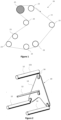
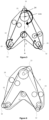
- the removable device 10 comprises a plurality of support elements 12, 14.
- the support elements 12, 14 are preferably connected to a frame 13.
- the support element 12, 14 are arranged to support an endless ribbon 11.
- the removable device 10 is adapted to be engaged over a conveyor system 20.
- each support element 12 is located at a specific position according to the frame 13 in order to allow the cooperation of said removable device 10 with the conveyor system 20.
- the specific location of each support element 10 on the frame 13 of the removable device 10 allows the cooperation between the removable device 10 and the conveyor system 20 without any interference between elements of the conveyor system 20 and of the removable device 10 that would block said cooperation.
- the removable device 10 comprises guiding elements for engaging the removable device 10 in the conveyor system 20.
- the guiding elements may comprise a sliding element and/or a rail or a longitudinal groove. Those guiding elements advantageously allow easing the cooperation between the removable device 10 and the conveyor system 20.
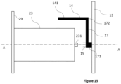
- the removable device 10 may comprise suspension points 15 to support at least one extremity 231 of a roller 23 of the conveyor system 20.
- Said suspension points 15 may comprise bearings.
- Suspension points 15 allow advantageously to reinforce the cooperation between the removable device 10 and the conveyor system 20 when the removable device 10 is engaged over the conveyor system 20.
- the bearings are advantageously designed to cooperate with a shaft of a roller of the conveyor system.
- At least two rollers 23 of the conveyor system are arranged in such a way than the longitudinal axis of said roller and the rotation axis A-A of the support element 12, 14 merge when the removable device 10 is engaged over the conveyor system 20.
- the removable device 10 comprises the endless ribbon 11.
- the endless ribbon 11 may be already inked.
- One advantage is to be able to install a new ribbon in a conveyor system from which an old ribbon has already been removed.
- each support element 12 of the removable device 10 is connected to a first face of the frame 13. It allows advantageously to let another face of the frame 13 free to install other elements. It also advantageously allows a user to easily manipulate the removable device 10, for example by pushing the removable device 10 on the free face of the frame 13 to install the removable device 10 in the conveyor system 20.
- the free face of the frame 13 comprises one or a plurality of handles.
- Each handle allows advantageously to ease the insertion of the removable device 10 in the conveyor system 20. It also allows moving the removable device 10 easily.
- the frame 13 may comprise a plastic material.
- the frame may also comprise a molded part, a composite part or a material comprising aluminum. In this configuration, the weight of the removable device 10 is advantageously reduced.
- the frame 13 and/or the conveyor system 20 may comprise one or a plurality of sensors.
- the frame is electrically connected to the conveyor system 20.
- the sensors may comprise position sensors. The position sensors allow advantageously to detect movement of the removable device 10 during the ribbon installation to prevent damaging both the conveyor system 20 and the removable device 10.
- the frame 13 comprises a locking system designed to maintain the removable device 10 engaged over the conveyor system 20.
- the locking system may comprise an automatic locking system.
- the locking system may comprise at least one sensor, said sensor being configured to detect cooperation between the frame 13 and the conveyor system 20.
- the frame 13 may comprise means of light emission.
- the means of light emission are designed to light the conveyor system 20. This means of light emission is located to provide enlightenment of the conveyor system during the process of engaging the removable device 10 to advantageously prevent damaging any element of both the removable device 10 and the conveyor system 20.
- the support elements 12,14 comprise a convex portion to support the endless ribbon 11.
- the convex portion comprises an outer convex face designed to support the endless ribbon 11.
- the convex portion allows advantageously to reduce local tension in the endless ribbon 11.
- At least one support element 12,14 is connected to the frame 13 of the removable device 10 with a mobile link.
- the mobile link allows preferably at least one degree of freedom.
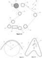
- At least one support element 12,14 is movable from a first position to a second position, preferably according to the degree of freedom allowed by the mobile link.
- the support element may be movable from the first position to the second position by a revolution displacement around the A-A axis.
- the first position of each support element 12,14 allows maintaining the endless ribbon 11 on their respective convex portion with a first predefined tension.
- the second position allows reducing the tension in the endless ribbon 11.
- the transition between the first position and the second position advantageous allows the installation of the ribbon in the conveyor system 20.
- the first position advantageously allows installing the removable device without damaging the ribbon.
- the first position also allows stretching the ribbon in such a way that the ribbon is not in contact with rollers in the conveyor system.
- the second position advantageously allows reducing the tension in the ribbon until the ribbon reaches the ribbon path in the conveyor system.
- the removable device 10 may be removed from the conveyor system 20 after it has been engaged over said conveyor system 20, when each support element 12,14 is in the first position. It advantageously allows replacing an endless ribbon 11 that has reached the end of its lifetime.
- each support element 12 of the removable device 10 is in the first position when each support element 12 of the removable device 10 is supporting the endless ribbon 11.
- the first position allows each support element 12,14 of the removable device to support the endless ribbon 11 when a new endless ribbon 11 needs to be installed in the conveyor system 20 or when a used endless ribbon needs to be removed from the conveyor system 20.
- each support element 12 of the removable device 10 is in the first position when the removable device 10 is engaged over the conveyor system 20.
- the endless ribbon 11 is advantageously ready to be installed in the conveyor system.
- each support element may comprise an arm 16,17 ensuring a mechanical connection between the convex portion and the frame.
- the connection between the arm and the frame is ensured by a pivot link.
- the arm 16, 17 is mechanically connected to the frame with a pivot link.
- the arm 17 comprises a distal end 172 connected to the convex portion 141 and a proximal end 171 connected to the frame 13 of the removable device.
- the proximal end is connected to the frame with one degree of freedom in rotation around the rotation axis A-A.
- the arm extends, between its distal and longitudinal end, in a direction sensibly perpendicular to the rotation axis A-A, preferably along a length superior to the radius of the corresponding roller 23 of the conveyor system. This arm advantageously allows arranging the convex portion in rotation around the roller 23 of the conveyor system 20.
- the convex portion when the convex portion is a roller, said roller of the support element is connected to the distal end with one degree of freedom in rotation.
- the roller advantageously preferably reduces friction between the support element 12 and the endless ribbon 11.
- the roller 121 is mechanically connected to the distal end of the arm 16. The proximal end of said arm 1
- At least one support element 14 comprises a portion of a hollow cylinder. In this configuration, the thickness of the convex portion is then advantageously reduced. Moreover, the removable device 10 is more compact.
- the support elements 14 comprise an inner face designed to face a roller of the conveyor system. Said inner face preferably comprises a concave shape. It advantageously eases the process of engaging the removable device 10 over the conveyor system 20 and reduces the bulk of the removable device 10.
- the inner face of the support elements 14 may have a curvature radius gratis or slightly superior to the curvature radius of the surface of a roller 23 facing the inner face in absolute value. This configuration allows reducing the first predefined tension.
- the convex portion may have a length gratis or slightly superior to the endless ribbon 11 width.
- length of the convex portion it should be understood the dimension of the convex portion along sensibly the ribbon width dimension.
- the support element 14 may comprise a stop.
- the stop advantageously prevents a displacement of the ribbon along the length of the convex portion.
- the stop may be located on the outer face of the convex portion.
- the stop may further be located near the distal end of the convex portion.
- the stop can be defined as a portion of the convex portion that has a superior thickness than the convex portion thickness. This configuration is particularly advantageous to prevent the endless ribbon from falling off the support elements 14.
- the support elements 14 comprises a gripping surface.
- the gripping surface is intended for supporting the endless ribbon 11.
- the gripping surface advantageously prevents the endless ribbon 11 to move when the endless ribbon is supported by the support elements of the removable device 10.
- the gripping surface may comprise a tissue.
- the gripping surface may have a lower friction in the direction according to the ribbon path than in the direction perpendicular to said ribbon path. It advantageously prevents the ribbon from slipping of the support element 14.
- At least two support elements 12,14 of the removable device 10 are in the second position when the endless ribbon 11 is supported by at least two rollers 23 of the conveyor system 20.
- the removable device 10 may be removed from the conveyor system 20 when each support element 12,14 of the removable device is in the second position.
- the removable device 10 can advantageously be removed from the conveyor system 20 after the installation of the endless ribbon 11.
- the removable device 10 may be inserted in the conveyor system 20 when each support element 12,14 is in the second position.
- each support element 12,14 of the removable device 10 may be moved in rotation around the axis of rotation A-A. This is particularly advantageous in order to replace the endless ribbon 11 in the conveyor system 20.
- the transition between the first position and the second position of at least one support element 12,14 of the removable device 10 allows to reduce the tension in the endless ribbon 11.
- each support element 12,14 of the removable device 10 is in the second position when each support element 12,14 of the removable device is withdrawn from a predefined ribbon path.
- a "predefined ribbon path” should be understood as the path defined by the support element 12,14 arrangement when each support element 12,14 is in the first position.
- a predefined ribbon path could also be any path that would be drawn by another arrangement of elements that would support the endless ribbon 11.
- At least one support element is free in rotation around a rotation axis A-A.
- At least one support element 12,14 is free in rotation in relation to the frame along at least 90°, preferably 180° around the rotation axis A-A. This rotation defines a circular trajectory around the rotation axis A-A.
- the rotation of at least one support element 12,14 of the removable device 10 around the rotation axis A-A allows advantageously to drop off the endless ribbon 11 on each roller 23 of the conveyor system 20.
- At least one pivot link connecting at least one arm 16,17 to the frame 13 allows a rotation of at least 90°, preferably 180° of said at least one arm 16,17 around the rotation axis A-A.
- One advantage is to shift the ribbon from a position wherein it is supported by the support elements to a position wherein it is supported by the rollers of the conveyor system.
- the angular distance ⁇ between two ends 141 of the section of the convex portion in a plane perpendicular to the axis of rotation A-A is less than 270°, preferably less than 180° or 120°.
- the angular distance ⁇ is measured in the section from the point of the axis A-A in said section according to a plane perpendicular to the rotation axis A-A.
- One advantage is to ensure that the rotation of the support element 12, 14 will allow shifting the endless ribbon 11 to a roller 23 of the conveyor system 20.
- Another advantage is to ensure a maximal size of the support element of the removable device.
- the rotation axis A-A of one support element 12,14 of the removable device 10 is parallel or sensibly parallel to the rotation axis of one roller 23 of the conveyor system 20. It allows advantageously the rotation of each support element 12,14 around each roller 23 with no contacts when the removable device 10 is engaged over the conveyor system 20.
- each support element 12,14 of the removable device 10 is in an intermediate position between the first and the second position. In this configuration, the tension in the endless ribbon 11 is advantageously maintained.
- each support element 12,14 of the removable device 10 is in the second position after a rotation of 180° around the rotation axis.
- the tension in the endless ribbon 11 has been advantageously reduced and the endless ribbon 11 is now supported by at least two rollers 23 of the conveyor system.
- each support element 12,14 allows advantageously to drop off the endless ribbon 11 on each roller 23 of the conveyor system 20.
- each support element 12,14 of the removable device 10 is still in contact with the endless ribbon 11 while each support element 12,14 of the removable device 10 moves in rotation around one roller 23 of the conveyor system 20.
- the tension in the endless ribbon 11 is advantageously maintained during the transition between the first and the second position.
- At least one support element 12,14 is designed to move in rotation around the axis A-A independently of one another. In this configuration, it allows advantageously to drop off the endless ribbon 11 little by little on each roller 23 of the conveyor system 20.
- the removable device 10 is designed in such a way that the movement of at least one support element 12,14 according to the mobile link drives a similar movement of another support element 12, 14 of the removable device 10.
- the endless ribbon 11 may advantageously be dropped off on each roller 23 of the conveyor system 20 in once.
- At least one support element 12,14 is free in translation along a second degree of freedom in relation to the frame 13.
- the frame may comprise a slide.
- the translation of one of the support elements 12,14 advantageously allows changing the tension in the endless ribbon 11.
- the installation of the endless ribbon 11 is advantageously eased.
- the risk of damaging the endless ribbon 11 during the installation is advantageously reduced.
- the slide allows the translation of the support element 12,14 between two positions: an outer position and an inner position wherein the tension of the ribbon is lower than in the outer position.
- the removable device 10 may further comprise a loaded spring to automatically bring the support element back to the inner position.
- the removable device 10 may comprise an interface.
- the interface comprises controls means.
- the control means are configured to control the movement of at least one support element between the first and the second position.
- the control means are mechanically connected to at least one support element 12,14.
- the control means may comprise a motor driven by the interface and driving the movement of the support elements 12, 14.
- the interface may comprise an actuator.
- the actuator is configured to activate the control means to control the movement of the support element from the first to the second position or from the second to the first position.
- control means advantageously allow a user to control the movement of at least one support element 12,14 of the removable device 10.
- One advantage of the invention is that the endless ribbon 11 stays under tension during the steps of installing the ribbon in the conveyor system and removing the ribbon from the conveyor system 20.
- the support elements 12, 14 are arranged on the frame in such a way that they draw a path sensibly equal to the length of the endless ribbon 11.
- the rollers 23 are arranged in the conveyor system 20 in such a way that they draw a path sensibly equal to the length of the endless ribbon 11.
- the interface comprises electronic means to drive the control means.
- the actuator may mechanically control the control means to actuate the movement of the support element.
- the actuator may comprise a handle to control the support element.
- the actuator may also comprise electronic means such as a button.
- the controls may comprise a motor to drive the support element.
- the interface may be designed to control the movement of two support elements 12,14 independently of one another.
- the interface or the control means may also be designed to move two support elements in a synchronized manner.
- the interface may also be designed to move two support elements to the first or second position according to a predefined sequence.
- the predefined sequence may include:
- the interface may comprise an actuator which can be actuated by a user to initiate the predefined sequence.
- This configuration is particularly advantageous if the user wants to drop off the endless ribbon 11 little by little in the conveyor system. It may advantageously optimize the installation of the ribbon to prevent damages on the ribbon.
- the predefined sequence may be the motion of each support element 12,14 to the first or second position in the same rotation direction and at the same time.
- the removable device comprises at least one sensor to monitor the movement of the support elements and preferably detect a deviation between the predefined sequence and the movement monitored of the support elements.
- the interface may comprise means to reverse or to stop an initiated sequence. This is particularly advantageous in the case where the user wants to prevent damaging both the removable device 10 and the conveyor system 20 when the installation goes wrong.
- the removable device 10 and/or the conveyor system 20 comprise recording means.
- the recording means may be designed to film the installation or the removal of the endless ribbon 11 in the conveyor system 20.
- the recording means may be connected to a screen. This configuration is particularly advantageous if the user wants to follow the installation or the removal of the endless ribbon 11 in real time.
- the invention further relates to a system comprising a removable device 10 and a conveyor system 20.
- the conveyor system 20 is adapted to cooperate with the removable device 10.
- the removable device is the same as according to the invention.
- a system according to this aspect of the invention is illustrated in reference to figure 4 .
- the first circumferential portion 24 of each roller 23 may be in contact with one support element 12,14 of the removable device when each support element 12,14 of the removable device is in the first position.
- This configuration allows advantageously to reinforce the stability of the removable device 10 and the conveyor system 20. Another advantage is to make sure that the endless ribbon 11 will be dropped off without being damaged on each roller 23 of the conveyor system 20 after the transition between the first and the second position of each support element 12,14 of the removable device 10.
- the cooperation between the removable device 10 and the conveyor system 20 may be maintained by securing means.
- the securing means may be a locking system. It should be understood by “cooperation” the fact that the removable device 10 is engaged over the conveyor system 20.
- This configuration is particularly advantageous to ensure that the frame 13 of the removable device 10 will be fixed during the installation of the ribbon in the conveyor system 20.
- Another advantage of this configuration is to possibly ensure that the frame 13 of the removable device 10 will be fixed to the conveyor system 20 during a step of printing.
- the system may comprise an alarm.
- the alarm may be actuated by the position sensors.
- the system may comprise an endless ribbon.
- the endless ribbon comprises a protecting sheet on its outer surface.
- the protective sheet may comprise a tongue.
- the tongue may be unrolled to separate the endless ribbon from the protective sheet. This configuration allows advantageously an easy installation of the endless ribbon 11 in the conveyor system 20.
- the invention further relates to a thermal printing apparatus 30 comprising a system according to the invention.
- the system is the same system as the system according to the second aspect of the invention.
- the thermal transfer printing apparatus comprises a printhead 27.
- the printhead allows advantageously to transfer ink from the ribbon to a substrate, using thermal transfer.
- the thermal transfer printing apparatus further comprises a coater to continuously coat the outer face of the ribbon with new ink.
- the coater 26 a slot-die coating device, an ink roller or any coating device known by the skilled person to coat a ribbon.
- the thermal printing apparatus 30 comprises a coater 26.
- the coater allows advantageously to coat the ribbon when the ink has been used to print.
- the removable device is foldable.
- the frame of the removable device is in several portions connected by a pivot connection, for example by a hinge 3.
- One advantage is to facilitate the transport and storage of such removable device.
- the removable device is packaged with an endless ribbon already arranged around the support elements 12, 14.
Landscapes
- Impression-Transfer Materials And Handling Thereof (AREA)
- Delivering By Means Of Belts And Rollers (AREA)
- Structure Of Belt Conveyors (AREA)
- Electronic Switches (AREA)
Claims (15)
- Abnehmbare Vorrichtung (10) zum Einführen eines Endlosbands in ein Fördersystem einer Thermotransferdruckvorrichtung, umfassend:• einen Rahmen (13);• mindestens zwei Stützelemente (12, 14), um ein Endlosband (11) zu stützen, wobei jedes Stützelement (12, 14) um eine Drehachse (A-A) herum drehbar ist; dadurch gekennzeichnet, dass jedes Stützelement umfasst:- einen konvexen Abschnitt, um einen Abschnitt des Endlosbands (11) zu stützen; und- einen Arm (13), der ein distales Ende aufweist, das mechanisch mit dem konvexen Abschnitt verbunden ist, und ein proximales Ende, das mechanisch mit dem Rahmen (13) durch eine Drehverbindung verbunden ist, die eine Drehung des Stützelements um die Drehachse (A-A) herum ermöglicht.
- Abnehmbare Vorrichtung (10) nach Anspruch 1, dadurch gekennzeichnet, dass jedes Stützelement (12, 14) mindestens 90°, vorzugsweise 180°, um die Drehachse (A-A) herum frei drehbar ist.
- Abnehmbare Vorrichtung (10) nach Anspruch 1 oder 2, dadurch gekennzeichnet, dass eines der mindestens zwei Stützelemente (12, 14) mit mindestens einem Grad Bewegungsfreiheit mit dem Rahmen verbunden ist.
- Abnehmbare Vorrichtung (10) nach Anspruch 1 bis 3, wobei jedes Stützelement (12, 14) zwischen mindestens zwei Positionen um die Drehachse herum beweglich ist, wobei die erste Position jedes Stützelements (12, 14) das Endlosband (11) an ihrem jeweiligen konvexen Abschnitt auf einer ersten vordefinierte Spannung hält, wobei die zweite Position eine Reduzierung der ersten vordefinierten Spannung ermöglicht.
- Abnehmbare Vorrichtung (10) nach Anspruch 1 bis 4, dadurch gekennzeichnet, dass der konvexe Abschnitt eines Stützelements (14) einen Abschnitt eines Hohlzylinders (14) umfasst.
- Abnehmbare Vorrichtung (10) nach Anspruch 1 bis 4, dadurch gekennzeichnet, dass der konvexe Abschnitt eines Stützelements (12) einen frei drehbaren Zylinder mit dem distalen Ende des Arms (13) entlang der Längsachse des Zylinders umfasst.
- Thermotransferdruckvorrichtung (30), umfassend eine abnehmbare Vorrichtung (10) nach einem der Ansprüche 1 bis 6 und ein Fördersystem (20), umfassend mindestens zwei Rollen (20), um das Endlosband auf einem ersten Umfangsabschnitt (24) jeder Rolle zu stützen, wobei das Fördersystem an eine Kooperation mit der abnehmbaren Vorrichtung angepasst ist.
- Thermotransferdruckvorrichtung (30) nach Anspruch 7, wobei die abnehmbare Vorrichtung (10) das Endlosband (11) umfasst, wobei das Endlosband (11) von mindestens zwei Stützelementen (12, 14) der abnehmbaren Vorrichtung (10) getragen wird.
- Thermotransferdruckvorrichtung (30) nach Anspruch 7 oder 8, wobei die abnehmbare Vorrichtung (10) Kooperationselemente zum Einrasten jedes Stützelements (12, 14) in das Fördersystem (20) umfasst.
- Thermotransferdruckvorrichtung (30) nach einem der Ansprüche 7 bis 9, wobei jedes Stützelement (12, 14) zwischen mindestens zwei Positionen um die Drehachse beweglich ist, wobei die erste Position jedes Stützelements (12, 14) das Endlosband (11) auf ihrem jeweiligen konvexen Abschnitt auf einer ersten vordefinierten Spannung hält, wobei die zweite Position eine Reduzierung der ersten vordefinierten Spannung ermöglicht,
und dadurch gekennzeichnet, dass die abnehmbare Vorrichtung (10) so angepasst ist, dass sie aus dem Fördersystem (20) entfernt werden kann, wenn sich jedes Stützelement (12, 14) in der ersten oder zweiten Position befindet. - Thermotransferdruckvorrichtung (30) nach Anspruch 10, dadurch gekennzeichnet, dass sich jedes Stützelement (12, 14) in seiner zweiten Position befindet, wenn jedes Stützelement (12, 14) aus einem vordefinierten, vorzugsweise durch die Stützelementanordnung in der ersten Position vordefinierten Bandpfad zurückgezogen wird.
- Thermotransferdruckvorrichtung (30) nach Anspruch 10 oder 11, wobei die abnehmbare Vorrichtung so ausgebildet ist, dass sie entlang mindestens zwei Rollen (23) des Fördersystems (20) eingerastet wird, wobei jedes Stützelement (12, 14) zwischen der ersten und der zweiten Position um eine Rolle (23) des Fördersystems (20) herum beweglich ist, wenn die abnehmbare Vorrichtung (10) über das Fördersystem (20) eingerastet wird:• in der ersten Position ist jedes Stützelement (12, 14) so angeordnet, dass es den ersten Umfangsabschnitt (24) einer Rolle (23) des Fördersystems (20) abdeckt;• in der zweiten Position ermöglicht jedes Stützelement (12, 14) einen freien Durchgang des Endlosbands (11) entlang des ersten Umfangsabschnitts (24).
- Thermotransferdruckvorrichtung (30) nach Anspruch 12, dadurch gekennzeichnet, dass die Drehachse (A-A) eines Stützelements (12, 14) der abnehmbaren Vorrichtung (10) parallel zur Drehachse einer Rolle (23) des Fördersystems (20) ist.
- System, das eine abnehmbare Vorrichtung nach einem der Ansprüche 1 bis 6 umfasst, wobei die abnehmbare Vorrichtung (10) mindestens zwei Teile (1, 2) umfasst, die an mindestens einem Drehpunkt (3) verbunden sind und ferner ein Endlosband (11) umfasst, das um die Stützelemente der abnehmbaren Vorrichtung installiert ist.
- System nach Anspruch 14, wobei das Endlosband eingefärbt ist.
Applications Claiming Priority (2)
| Application Number | Priority Date | Filing Date | Title |
|---|---|---|---|
| EP21315013.9A EP4035902A1 (de) | 2021-01-29 | 2021-01-29 | Abnehmbare vorrichtung zur installation eines endlosen bandes |
| PCT/EP2022/052137 WO2022162195A1 (en) | 2021-01-29 | 2022-01-28 | Removable device for the installation of an endless ribbon |
Publications (3)
| Publication Number | Publication Date |
|---|---|
| EP4284653A1 EP4284653A1 (de) | 2023-12-06 |
| EP4284653B1 true EP4284653B1 (de) | 2024-10-23 |
| EP4284653C0 EP4284653C0 (de) | 2024-10-23 |
Family
ID=74859866
Family Applications (2)
| Application Number | Title | Priority Date | Filing Date |
|---|---|---|---|
| EP21315013.9A Withdrawn EP4035902A1 (de) | 2021-01-29 | 2021-01-29 | Abnehmbare vorrichtung zur installation eines endlosen bandes |
| EP22702283.7A Active EP4284653B1 (de) | 2021-01-29 | 2022-01-28 | Abnehmbare vorrichtung zur installation eines endlosen bandes |
Family Applications Before (1)
| Application Number | Title | Priority Date | Filing Date |
|---|---|---|---|
| EP21315013.9A Withdrawn EP4035902A1 (de) | 2021-01-29 | 2021-01-29 | Abnehmbare vorrichtung zur installation eines endlosen bandes |
Country Status (7)
| Country | Link |
|---|---|
| US (1) | US12005723B2 (de) |
| EP (2) | EP4035902A1 (de) |
| JP (1) | JP2024504756A (de) |
| KR (1) | KR20230135139A (de) |
| CN (1) | CN117062720A (de) |
| ES (1) | ES3001707T3 (de) |
| WO (1) | WO2022162195A1 (de) |
Families Citing this family (1)
| Publication number | Priority date | Publication date | Assignee | Title |
|---|---|---|---|---|
| EP4438316A1 (de) | 2023-03-29 | 2024-10-02 | Armor | Mehrschichtige bandvorrichtung mit einem endlosband für thermotransferdruckgerät |
Family Cites Families (13)
| Publication number | Priority date | Publication date | Assignee | Title |
|---|---|---|---|---|
| GB622088A (en) | 1946-07-10 | 1949-04-26 | Ncr Co | Improvements relating to means for inking ribbons |
| US3728963A (en) * | 1970-08-07 | 1973-04-24 | Ibm | Ribbon feed cartridge |
| DE102008032804B4 (de) * | 2007-12-17 | 2018-07-05 | Francotyp-Postalia Gmbh | Transportvorrichtung für zu bedruckende flache Güter |
| US8922611B1 (en) | 2013-10-09 | 2014-12-30 | Markem-Imaje Corporation | Apparatus and method for thermal transfer printing |
| GB201318444D0 (en) | 2013-10-18 | 2013-12-04 | Videojet Technologies Inc | Printing |
| CN104175729A (zh) | 2014-08-19 | 2014-12-03 | 上海美声服饰辅料有限公司 | 色带可循环使用的热转印打印机 |
| CN203995148U (zh) | 2014-08-19 | 2014-12-10 | 上海美声服饰辅料有限公司 | 一种色带可循环使用的热转印打印机 |
| EP3374190B1 (de) * | 2015-11-13 | 2021-07-07 | Entrust Datacard Corporation | Bandzufuhraufnahme |
| CN110001191A (zh) * | 2017-12-15 | 2019-07-12 | 多佛欧洲公司 | 用于热转移印刷的设备和方法 |
| US20200047488A1 (en) * | 2018-08-07 | 2020-02-13 | Canon Kabushiki Kaisha | Protective sheet, endless belt laminate, endless belt assembly, package and mounting jig |
| CN109435503B (zh) | 2018-12-28 | 2024-04-05 | 湖南鼎一致远科技发展有限公司 | 一种色带收放装置及包含其的热转印打印机 |
| CN209920746U (zh) | 2019-03-08 | 2020-01-10 | 湖南长城信息金融设备有限责任公司 | 一种卡片快速烫色装置 |
| CN111791616B (zh) | 2020-08-12 | 2025-04-25 | 湖南鼎一致远科技发展有限公司 | 色带盒可替换的打印组件及具有其的热转印打印机 |
-
2021
- 2021-01-29 EP EP21315013.9A patent/EP4035902A1/de not_active Withdrawn
-
2022
- 2022-01-28 KR KR1020237029145A patent/KR20230135139A/ko active Pending
- 2022-01-28 ES ES22702283T patent/ES3001707T3/es active Active
- 2022-01-28 CN CN202280022786.XA patent/CN117062720A/zh active Pending
- 2022-01-28 US US18/263,266 patent/US12005723B2/en active Active
- 2022-01-28 EP EP22702283.7A patent/EP4284653B1/de active Active
- 2022-01-28 WO PCT/EP2022/052137 patent/WO2022162195A1/en not_active Ceased
- 2022-01-28 JP JP2023545754A patent/JP2024504756A/ja active Pending
Also Published As
| Publication number | Publication date |
|---|---|
| WO2022162195A1 (en) | 2022-08-04 |
| EP4284653A1 (de) | 2023-12-06 |
| US12005723B2 (en) | 2024-06-11 |
| CN117062720A (zh) | 2023-11-14 |
| EP4284653C0 (de) | 2024-10-23 |
| EP4035902A1 (de) | 2022-08-03 |
| KR20230135139A (ko) | 2023-09-22 |
| ES3001707T3 (en) | 2025-03-05 |
| US20240034082A1 (en) | 2024-02-01 |
| JP2024504756A (ja) | 2024-02-01 |
Similar Documents
| Publication | Publication Date | Title |
|---|---|---|
| CN100335371C (zh) | 薄膜输送装置和自动包装装置 | |
| US6553746B1 (en) | Device for automatically changing reels of film | |
| EP4284653B1 (de) | Abnehmbare vorrichtung zur installation eines endlosen bandes | |
| US5526747A (en) | Device for replacing printing plates in rotary printing presses | |
| US7950602B2 (en) | Device and method for moving reels in an unwinder | |
| JP2005523852A (ja) | 環状軌道構造を有する包装装置およびフィルム供給装置 | |
| EP0184234A1 (de) | Mehrfarbiger Drucker | |
| RU2617509C9 (ru) | Система удаления краски машины глубокой печати и машина глубокой печати, содержащая ее | |
| US6843297B2 (en) | Laminate cartridge | |
| US20140097288A1 (en) | Sheet feeder and image forming apparatus | |
| ITBO930376A1 (it) | Dispositivo di prelievo e trasferimento di bobine da un magazzino ad una unita' di svolgitura. | |
| ES2919598T3 (es) | Impresora de etiquetas | |
| KR100318642B1 (ko) | 인쇄용카트리지 | |
| US20050056719A1 (en) | Splicing vehicle | |
| WO1999067133A2 (en) | Method and device in connection with wrapping of a piece | |
| KR19990070826A (ko) | 레이블 권회장치 | |
| JP2582679B2 (ja) | 印刷機のローラー交換装置 | |
| WO2000068091A1 (en) | Label transfering system | |
| JP2024020159A (ja) | エンドレスリボンを支える取り外し可能な支持装置 | |
| KR20230141231A (ko) | 버퍼링유닛 및 이를 이용한 라벨부착장치 | |
| JP2001106216A (ja) | ラベル発行装置 | |
| JP3420806B2 (ja) | ロール交換装置 | |
| US7522179B2 (en) | Universal donor cartridge | |
| JP2019209554A (ja) | プリンタ | |
| US20240109337A1 (en) | Label Printing and Attaching System |
Legal Events
| Date | Code | Title | Description |
|---|---|---|---|
| STAA | Information on the status of an ep patent application or granted ep patent |
Free format text: STATUS: UNKNOWN |
|
| STAA | Information on the status of an ep patent application or granted ep patent |
Free format text: STATUS: THE INTERNATIONAL PUBLICATION HAS BEEN MADE |
|
| PUAI | Public reference made under article 153(3) epc to a published international application that has entered the european phase |
Free format text: ORIGINAL CODE: 0009012 |
|
| STAA | Information on the status of an ep patent application or granted ep patent |
Free format text: STATUS: REQUEST FOR EXAMINATION WAS MADE |
|
| 17P | Request for examination filed |
Effective date: 20230818 |
|
| AK | Designated contracting states |
Kind code of ref document: A1 Designated state(s): AL AT BE BG CH CY CZ DE DK EE ES FI FR GB GR HR HU IE IS IT LI LT LU LV MC MK MT NL NO PL PT RO RS SE SI SK SM TR |
|
| DAV | Request for validation of the european patent (deleted) | ||
| DAX | Request for extension of the european patent (deleted) | ||
| GRAP | Despatch of communication of intention to grant a patent |
Free format text: ORIGINAL CODE: EPIDOSNIGR1 |
|
| STAA | Information on the status of an ep patent application or granted ep patent |
Free format text: STATUS: GRANT OF PATENT IS INTENDED |
|
| INTG | Intention to grant announced |
Effective date: 20240612 |
|
| GRAS | Grant fee paid |
Free format text: ORIGINAL CODE: EPIDOSNIGR3 |
|
| GRAA | (expected) grant |
Free format text: ORIGINAL CODE: 0009210 |
|
| STAA | Information on the status of an ep patent application or granted ep patent |
Free format text: STATUS: THE PATENT HAS BEEN GRANTED |
|
| AK | Designated contracting states |
Kind code of ref document: B1 Designated state(s): AL AT BE BG CH CY CZ DE DK EE ES FI FR GB GR HR HU IE IS IT LI LT LU LV MC MK MT NL NO PL PT RO RS SE SI SK SM TR |
|
| REG | Reference to a national code |
Ref country code: GB Ref legal event code: FG4D |
|
| REG | Reference to a national code |
Ref country code: CH Ref legal event code: EP |
|
| REG | Reference to a national code |
Ref country code: DE Ref legal event code: R096 Ref document number: 602022007065 Country of ref document: DE |
|
| REG | Reference to a national code |
Ref country code: IE Ref legal event code: FG4D |
|
| U01 | Request for unitary effect filed |
Effective date: 20241119 |
|
| U07 | Unitary effect registered |
Designated state(s): AT BE BG DE DK EE FI FR IT LT LU LV MT NL PT RO SE SI Effective date: 20241127 |
|
| U20 | Renewal fee for the european patent with unitary effect paid |
Year of fee payment: 4 Effective date: 20250127 |
|
| PG25 | Lapsed in a contracting state [announced via postgrant information from national office to epo] |
Ref country code: IS Free format text: LAPSE BECAUSE OF FAILURE TO SUBMIT A TRANSLATION OF THE DESCRIPTION OR TO PAY THE FEE WITHIN THE PRESCRIBED TIME-LIMIT Effective date: 20250223 Ref country code: HR Free format text: LAPSE BECAUSE OF FAILURE TO SUBMIT A TRANSLATION OF THE DESCRIPTION OR TO PAY THE FEE WITHIN THE PRESCRIBED TIME-LIMIT Effective date: 20241023 |
|
| PGFP | Annual fee paid to national office [announced via postgrant information from national office to epo] |
Ref country code: ES Payment date: 20250328 Year of fee payment: 4 |
|
| PG25 | Lapsed in a contracting state [announced via postgrant information from national office to epo] |
Ref country code: NO Free format text: LAPSE BECAUSE OF FAILURE TO SUBMIT A TRANSLATION OF THE DESCRIPTION OR TO PAY THE FEE WITHIN THE PRESCRIBED TIME-LIMIT Effective date: 20250123 |
|
| PG25 | Lapsed in a contracting state [announced via postgrant information from national office to epo] |
Ref country code: GR Free format text: LAPSE BECAUSE OF FAILURE TO SUBMIT A TRANSLATION OF THE DESCRIPTION OR TO PAY THE FEE WITHIN THE PRESCRIBED TIME-LIMIT Effective date: 20250124 |
|
| PG25 | Lapsed in a contracting state [announced via postgrant information from national office to epo] |
Ref country code: PL Free format text: LAPSE BECAUSE OF FAILURE TO SUBMIT A TRANSLATION OF THE DESCRIPTION OR TO PAY THE FEE WITHIN THE PRESCRIBED TIME-LIMIT Effective date: 20241023 |
|
| PG25 | Lapsed in a contracting state [announced via postgrant information from national office to epo] |
Ref country code: RS Free format text: LAPSE BECAUSE OF FAILURE TO SUBMIT A TRANSLATION OF THE DESCRIPTION OR TO PAY THE FEE WITHIN THE PRESCRIBED TIME-LIMIT Effective date: 20250123 |
|
| PG25 | Lapsed in a contracting state [announced via postgrant information from national office to epo] |
Ref country code: SM Free format text: LAPSE BECAUSE OF FAILURE TO SUBMIT A TRANSLATION OF THE DESCRIPTION OR TO PAY THE FEE WITHIN THE PRESCRIBED TIME-LIMIT Effective date: 20241023 |
|
| PG25 | Lapsed in a contracting state [announced via postgrant information from national office to epo] |
Ref country code: SK Free format text: LAPSE BECAUSE OF FAILURE TO SUBMIT A TRANSLATION OF THE DESCRIPTION OR TO PAY THE FEE WITHIN THE PRESCRIBED TIME-LIMIT Effective date: 20241023 |
|
| PG25 | Lapsed in a contracting state [announced via postgrant information from national office to epo] |
Ref country code: CZ Free format text: LAPSE BECAUSE OF FAILURE TO SUBMIT A TRANSLATION OF THE DESCRIPTION OR TO PAY THE FEE WITHIN THE PRESCRIBED TIME-LIMIT Effective date: 20241023 |
|
| PLBE | No opposition filed within time limit |
Free format text: ORIGINAL CODE: 0009261 |
|
| STAA | Information on the status of an ep patent application or granted ep patent |
Free format text: STATUS: NO OPPOSITION FILED WITHIN TIME LIMIT |
|
| PG25 | Lapsed in a contracting state [announced via postgrant information from national office to epo] |
Ref country code: MC Free format text: LAPSE BECAUSE OF FAILURE TO SUBMIT A TRANSLATION OF THE DESCRIPTION OR TO PAY THE FEE WITHIN THE PRESCRIBED TIME-LIMIT Effective date: 20241023 |
|
| 26N | No opposition filed |
Effective date: 20250724 |
|
| PG25 | Lapsed in a contracting state [announced via postgrant information from national office to epo] |
Ref country code: IE Free format text: LAPSE BECAUSE OF NON-PAYMENT OF DUE FEES Effective date: 20250128 |
|
| REG | Reference to a national code |
Ref country code: CH Ref legal event code: U11 Free format text: ST27 STATUS EVENT CODE: U-0-0-U10-U11 (AS PROVIDED BY THE NATIONAL OFFICE) Effective date: 20260204 |
|
| U20 | Renewal fee for the european patent with unitary effect paid |
Year of fee payment: 5 Effective date: 20260130 |
|
| PGFP | Annual fee paid to national office [announced via postgrant information from national office to epo] |
Ref country code: GB Payment date: 20260128 Year of fee payment: 5 |
|
| PGFP | Annual fee paid to national office [announced via postgrant information from national office to epo] |
Ref country code: CH Payment date: 20260204 Year of fee payment: 5 |