EP4284087B1 - Verfahren und vorrichtung zur fusion von drahtloser kommunikation und drahtloser erfassung - Google Patents
Verfahren und vorrichtung zur fusion von drahtloser kommunikation und drahtloser erfassung Download PDFInfo
- Publication number
- EP4284087B1 EP4284087B1 EP21920795.8A EP21920795A EP4284087B1 EP 4284087 B1 EP4284087 B1 EP 4284087B1 EP 21920795 A EP21920795 A EP 21920795A EP 4284087 B1 EP4284087 B1 EP 4284087B1
- Authority
- EP
- European Patent Office
- Prior art keywords
- signal
- slot
- transmission
- wireless communication
- wireless sensing
- Prior art date
- Legal status (The legal status is an assumption and is not a legal conclusion. Google has not performed a legal analysis and makes no representation as to the accuracy of the status listed.)
- Active
Links
Images


Classifications
-
- G—PHYSICS
- G01—MEASURING; TESTING
- G01S—RADIO DIRECTION-FINDING; RADIO NAVIGATION; DETERMINING DISTANCE OR VELOCITY BY USE OF RADIO WAVES; LOCATING OR PRESENCE-DETECTING BY USE OF THE REFLECTION OR RERADIATION OF RADIO WAVES; ANALOGOUS ARRANGEMENTS USING OTHER WAVES
- G01S7/00—Details of systems according to groups G01S13/00, G01S15/00, G01S17/00
- G01S7/003—Transmission of data between radar, sonar or lidar systems and remote stations
- G01S7/006—Transmission of data between radar, sonar or lidar systems and remote stations using shared front-end circuitry, e.g. antennas
-
- G—PHYSICS
- G01—MEASURING; TESTING
- G01S—RADIO DIRECTION-FINDING; RADIO NAVIGATION; DETERMINING DISTANCE OR VELOCITY BY USE OF RADIO WAVES; LOCATING OR PRESENCE-DETECTING BY USE OF THE REFLECTION OR RERADIATION OF RADIO WAVES; ANALOGOUS ARRANGEMENTS USING OTHER WAVES
- G01S13/00—Systems using the reflection or reradiation of radio waves, e.g. radar systems; Analogous systems using reflection or reradiation of waves whose nature or wavelength is irrelevant or unspecified
- G01S13/74—Systems using reradiation of radio waves, e.g. secondary radar systems; Analogous systems
- G01S13/76—Systems using reradiation of radio waves, e.g. secondary radar systems; Analogous systems wherein pulse-type signals are transmitted
- G01S13/765—Systems using reradiation of radio waves, e.g. secondary radar systems; Analogous systems wherein pulse-type signals are transmitted with exchange of information between interrogator and responder
-
- G—PHYSICS
- G01—MEASURING; TESTING
- G01S—RADIO DIRECTION-FINDING; RADIO NAVIGATION; DETERMINING DISTANCE OR VELOCITY BY USE OF RADIO WAVES; LOCATING OR PRESENCE-DETECTING BY USE OF THE REFLECTION OR RERADIATION OF RADIO WAVES; ANALOGOUS ARRANGEMENTS USING OTHER WAVES
- G01S7/00—Details of systems according to groups G01S13/00, G01S15/00, G01S17/00
- G01S7/003—Transmission of data between radar, sonar or lidar systems and remote stations
-
- G—PHYSICS
- G01—MEASURING; TESTING
- G01S—RADIO DIRECTION-FINDING; RADIO NAVIGATION; DETERMINING DISTANCE OR VELOCITY BY USE OF RADIO WAVES; LOCATING OR PRESENCE-DETECTING BY USE OF THE REFLECTION OR RERADIATION OF RADIO WAVES; ANALOGOUS ARRANGEMENTS USING OTHER WAVES
- G01S7/00—Details of systems according to groups G01S13/00, G01S15/00, G01S17/00
- G01S7/02—Details of systems according to groups G01S13/00, G01S15/00, G01S17/00 of systems according to group G01S13/00
- G01S7/28—Details of pulse systems
- G01S7/285—Receivers
- G01S7/292—Extracting wanted echo-signals
-
- H—ELECTRICITY
- H04—ELECTRIC COMMUNICATION TECHNIQUE
- H04W—WIRELESS COMMUNICATION NETWORKS
- H04W72/00—Local resource management
- H04W72/50—Allocation or scheduling criteria for wireless resources
- H04W72/53—Allocation or scheduling criteria for wireless resources based on regulatory allocation policies
-
- H—ELECTRICITY
- H04—ELECTRIC COMMUNICATION TECHNIQUE
- H04W—WIRELESS COMMUNICATION NETWORKS
- H04W72/00—Local resource management
- H04W72/50—Allocation or scheduling criteria for wireless resources
- H04W72/535—Allocation or scheduling criteria for wireless resources based on resource usage policies
-
- H—ELECTRICITY
- H04—ELECTRIC COMMUNICATION TECHNIQUE
- H04B—TRANSMISSION
- H04B1/00—Details of transmission systems, not covered by a single one of groups H04B3/00 - H04B13/00; Details of transmission systems not characterised by the medium used for transmission
- H04B1/38—Transceivers, i.e. devices in which transmitter and receiver form a structural unit and in which at least one part is used for functions of transmitting and receiving
- H04B1/40—Circuits
- H04B1/44—Transmit/receive switching
-
- H—ELECTRICITY
- H04—ELECTRIC COMMUNICATION TECHNIQUE
- H04W—WIRELESS COMMUNICATION NETWORKS
- H04W72/00—Local resource management
- H04W72/04—Wireless resource allocation
- H04W72/044—Wireless resource allocation based on the type of the allocated resource
- H04W72/0446—Resources in time domain, e.g. slots or frames
Definitions
- the present disclosure relates to the field of communication technology, in particular to a method and an apparatus for integrating wireless communication and wireless sensing, and a processor-readable storage medium.
- Radar-based wireless sensing technology includes two modes, i.e., a passive sensing mode and an active sensing mode.
- a passive sensing mode a sensor obtains electromagnetic waves (e.g., infrared rays) emitted by a target object or reflected by the target object for sensing.
- the active sensing mode the sensor transmits electromagnetic waves and receives the electromagnetic waves reflected by the target object for sensing.
- a distance between the sensed target object and the sensor is unknown, so the sensor needs to receive a reflected signal corresponding to a sensing signal in real time.
- an electronic device may transmit a radio frequency (RF) pulse signal in the active phase of a periodic sensing cycle, and sense in the passive phase of the sensing cycle, a reflection of the RF pulse signal reflected from an object.
- the RF pulse signal is defined by a waveform for carrying communication data between electronic devices.
- the sensed RF pulse signal is at least a portion of the transmitted or reflected RF pulse signal, wherein the portion is equal to or greater than a threshold value for the object being within a sensing range of the first electronic device.
- the electronic device may also receive a communication signal from another electronic device during the passive phase.
- WO 2021/006711 A1 discloses a device capable of communication and radar operation that happen in the same frequency band. The communication and radar operation coexist in a time division manner.
- LIU FAN ET AL "Joint Radar and Communication Design: Applications, State-of-the-Art, and the Road Ahead", IEEE TRANSACTIONS ON COMMUNICATIONS, 2020-02-13 , discloses Joint Radar and Communications, JRC.
- a novel DFRC frame structure is proposed that complies with TDD protocols and which can be split into three stages for unifying similar radar and communication operations, namely 1) radar target search and communication channel estimation, 2) radar transmit beamforming and downlink communication and 3) radar target tracking and uplink communication.
- the present disclosure provides a method and an apparatus for integrating wireless communication and wireless sensing, so as to prevent the communication function from being adversely affected after the introduction of the sensing function into a system.
- the invention is set out in the appended set of claims.
- the wireless sensing signal is transmitted during the switching occasion of the transmission and reception of the wireless communication signal, and the echo signal corresponding to the wireless sensing signal is received after the wireless communication signal has been transmitted.
- the wireless sensing signal is transmitted during the switching occasion of the transmission and reception of the wireless communication signal, and the echo signal corresponding to the wireless sensing signal is received after the wireless communication signal has been transmitted.
- system and "network” may be replaced with each other.
- embodiments of the present disclosure is to provide a method for integrating wireless communication and wireless sensing, so as to prevent a communication function from being adversely affected after the introduction of a sensing function into a system.
- the present disclosure provides in an embodiment a method for integrating wireless communication and wireless sensing, which includes the following steps.
- Step 101 transmitting, by a communication device, a wireless sensing signal in a target slot position related to a switching point between signal transmission and signal reception of a wireless communication signal.
- the wireless sensing signal is used to detect information such as a distance or an image of a target object.
- the target object is a communication device such as a base station or a UE, or any other object such as a vehicle or a building.
- the communication device is a base station or a UE.
- the target slot positions for transmitting the wireless sensing signal are different.
- the base station transmits the wireless sensing signal at a position adjacent to a switching point between downlink transmission and uplink reception of the wireless communication signal.
- the terminal transmits the wireless sensing signal at a position adjacent to a switching point between uplink transmission and downlink reception of the wireless communication signal.
- the communication device determines whether there is the target object and determines the other sensing parameters of the target object.
- Step 102 receiving an echo signal corresponding to the wireless sensing signal in the case that a signal transmission slot of the wireless communication signal is ended.
- the communication device After the signal transmission slot of the wireless communication signal has been ended, the communication device starts to receive the echo signal corresponding to the wireless sensing signal. After the wireless sensing signal has been transmitted by the communication device, when there is the target object, the echo signal is reflected by the target object, and the communication device performs sensing processing in accordance with the echo signal.
- the base station starts to receive the echo signal corresponding to the wireless sensing signal.
- the communication device is a UE, after an uplink transmission slot of the wireless communication signal is ended, the UE starts to receive the echo signal corresponding to the wireless sensing signal.
- the wireless sensing signal is transmitted during the switching of the transmission and reception of the wireless communication signal, and the echo signal corresponding to the wireless sensing signal is received after the wireless communication signal has been transmitted.
- the wireless sensing signal is able to minimize a mutual influence between the wireless communication signal and the wireless sensing signal in inter-frequency multiplexing, thereby to reduce the requirement on a transceiver.
- the target slot position includes one of: a slot position with a duration of ⁇ before an end time point of a first slot, the first slot being a last signal transmission slot of the wireless communication signal; a slot position with a duration of ⁇ after a start time point of a second slot, the second slot being a slot after and adjacent to the last signal transmission slot of the wireless communication signal; or a slot position with a duration of ⁇ started before the end time point of the first slot and ended after the start time point of the second slot, where ⁇ represents a duration of each transmission of the wireless sensing signal.
- the first slot is a downlink slot
- the second slot is an idle slot or an uplink slot after the last signal transmission slot of the wireless communication signal.
- the first slot is an uplink slot
- the second slot is an idle slot or a downlink slow after the last signal transmission slot of the wireless communication signal.
- the target slot position is a time interval, and a slot adjacent to and after the last signal transmission slot of the wireless communication signal is an idle slot or a reception slot.
- the adjacent slot is an idle slot or an uplink slot
- the adjacent slot is an idle slot or a downlink slot.
- the duration ⁇ is started at a position of ⁇ 2 before the end time point of the first slot and ended at a position of ⁇ 2 after the start time point of the second slot.
- the specific time of the duration ⁇ before the end time point of the first slot may be equal to, or not equal to, the specific time of the duration ⁇ after the start time point of the second slot.
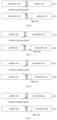
- the target slot position is a slot position corresponding to a time interval with a duration of ⁇ and at a tail of the last downlink transmission slot of the wireless communication signal in a frame structure, as indicated by (a1) and (a2) in Fig. 2 .
- a slot after and adjacent to the last signal transmission slot of the wireless communication signal i.e., the last downlink slot
- the adjacent slot is an idle slot.
- the target slot position is a slot corresponding to a time interval with a duration of ⁇ and at a header of the last downlink transmission slot of the wireless communication signal, as indicated by (b1) and (b2) in Fig. 3 .
- a slot after and adjacent to the last signal transmission slot of the wireless communication signal i.e., the last downlink slot
- the adjacent slot is an idle slot.
- the target slot position is a slot position corresponding to a time interval with a duration of ⁇ and crossing the end time point of the first slot and the start time point of the second slot, as indicated by (c1) and (c2) in Fig. 4 .
- a slot after and adjacent to the last signal transmission slot of the wireless communication signal i.e., the last downlink slot
- the adjacent slot is an idle slot.
- the target slot position is a slot position corresponding to a time interval with a duration of ⁇ and at a tail of the last uplink transmission slot of the wireless communication signal in a frame structure, as indicated by (a1) and (a2) in Fig. 5 .
- a slot after and adjacent to the last signal transmission slot of the wireless communication signal i.e., the last uplink slot
- the adjacent slot is an idle slot.
- the target slot position is a slot position corresponding to a time interval with a duration of ⁇ and at a header of an adjacent slot after the last uplink transmission slot of the wireless communication signal, as indicated by (b1) and (b2) in Fig. 6 .
- a slot after and adjacent to the last signal transmission slot of the wireless communication signal i.e., the last uplink slot
- the adjacent slot is an idle slot.
- the target slot position is a slot position corresponding to a time interval with a duration of ⁇ and crossing the end time point of the first slot and the start time point of the second slot, as indicated by (c1) and (c2) in Fig. 7 .
- a slot after and adjacent to the last signal transmission slot of the wireless communication signal i.e., the last uplink slot
- the adjacent slot is an idle slot.
- the communication device needs to perform transmission and reception operations simultaneously during the transmission of the wireless sensing signal, i.e., the communication device is provided with such a function of transmitting and receiving signals simultaneously on a same frequency band.
- a full duplexing scheme or a multi-Transmission Reception Point (TRP) cooperative sensing scheme is adopted by the communication device.
- the wireless sensing signal occupies an entire operating frequency band or a part of the operating frequency band corresponding to the target slot position.
- the wireless communication signal is transmitted or not transmitted on the other frequency band corresponding to the target slot position.
- the wireless sensing signal occupies a part of the operating frequency band corresponding to the target slot position and the wireless communication signal is transmitted on the other frequency band other than the part of operating frequency band, it is able to transmit the wireless sensing signal and the wireless communication signal in a frequency-division multiplexing manner, thereby to utilize the frequency resources to the greatest extent.
- the transmitting the wireless sensing signal in the target slot position related to the switching point between the signal transmission and the signal reception of the wireless communication signal includes one of the followings.
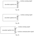
- the communication device transmits the wireless sensing signal on a part of the operating frequency band corresponding to the target slot position, and transmits the wireless communication signal on the other frequency band of the operating frequency band, as shown in Fig. 8c .
- the wireless sensing signal occupies a part of the frequency band, and the wireless communication signal occupies the other frequency band.
- the slot in Fig. 8c is a downlink slot
- the slot in Fig. 8c is an uplink slot.
- a hatched portion in Fig. 8c is a frequency band for transmitting the wireless sensing signal
- a blank portion of the operating frequency band is a frequency band for transmitting the wireless communication signal.
- the wireless sensing signal and the wireless communication signal are transmitted in a frequency-division multiplexing manner.
- the wireless sensing and the wireless communication are harmonized so as to be performed on a same operating frequency band, so it is able to utilize the frequency resources to the greatest extent.
- the transmitting the wireless sensing signal in the target slot position related to the switching point between the signal transmission and the signal reception of the wireless communication signal includes transmitting, within a sensing detection period, the wireless sensing signal for N times with a target period, where N ⁇ T1 ⁇ T, T1 represents the target period and it is an integral multiple of a duration of a subframe for transmitting the wireless communication signal, and T represents the sensing detection period.
- a same wireless sensing signal or different wireless sensing signals are transmitted, within the sensing detection period, for N times with the target period, so as to achieve a deblurring effect and/or scan an environment.
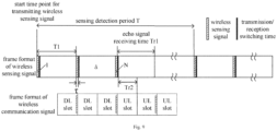
- Fig. 9 shows frame formats of the wireless sensing signal and the wireless communication signal.
- the wireless sensing signal is generated through a signal generation method widely used by a radar system, e.g., linear frequency modulation or pulse-phase modulation.
- the wireless sensing signal is transmitted with the target period T1 for N times, and a duration of each transmission of the wireless sensing signal is ⁇ , where N ⁇ T1 ⁇ T.
- the sensing detection period and the target period it is able to achieve a deblurring effect, and through transmitting the wireless sensing signal multiple times, it is able to improve the sensing accuracy.
- it is able to prevent the occurrence of such a circumstance where it is impossible to determine a transmission position of the echo signal when merely one period is provided and the echo signal is received within a next period rather than a period where the wireless sensing signal is transmitted.
- a switching time between the signal transmission and the signal reception of the wireless communication signal is zero.
- Tr2 represents the time for receiving the echo signal
- ⁇ represents a duration of each transmission of the wireless sensing signal
- Td1 represents a time of a transmission slot of the wireless communication signal
- T0 represents a switching time between the signal transmission and the signal reception of the wireless communication signal.
- a time window for receiving the echo signal corresponding to the wireless sensing signal is determined by a receiver of the communication device itself in accordance with a sensing detection range.
- the receiver of the communication device detects the echo signal during the reception of the echo signal, and determines an arrival time, a phase and intensity of the echo signal through a detection algorithm for a local wireless sensing signal and the echo signal, e.g., moving filtration, so as to sense the information about the target object, e.g., a target position, a pose or an image of the target object.
- the base station transmits the wireless sensing signal.
- the base station transmits the wireless sensing signal at a position adjacent to the switching point between the downlink transmission and the uplink reception, and after the downlink transmission has been ended, starts to receive the echo signal corresponding to the wireless sensing signal.
- the position adjacent to the switching point between the downlink transmission and the uplink reception refers to, in the frame structure, a position at a tail of a last slot for the downlink transmission (as shown in Fig. 2 ), a position at a header of a slot (an idle sot or an uplink slot) after the last slot for the downlink transmission (as shown in Fig. 3 ), or a position crossing the tail of the last slot and the header of the slot after the last slot (as shown in Fig. 4 ).
- the base station needs to transmit and receive the signals simultaneously, i.e., the base station is provided with a function of transmitting and receiving the signals simultaneously on a same frequency band.
- a full duplexing scheme or a multi-TRP cooperative sensing scheme is adopted by the base station.
- the wireless sensing signal is merely transmitted on the operating frequency band corresponding to the target slot position, i.e., the wireless sensing signal occupies the entire operating frequency band or a part of the operating frequency band, or the wireless communication signal and the wireless sensing signal are transmitted simultaneously in a frequency-division duplexing manner, as shown in Figs. 8a to 8c .
- the terminal transmits the wireless sensing signal.
- the terminal transmits the wireless sensing signal at a position adjacent to the switching point between the downlink transmission and the uplink reception, and after the downlink transmission has been ended, starts to receive the echo signal corresponding to the wireless sensing signal.
- the position adjacent to the switching point between the uplink transmission and the downlink reception refers to, in the frame structure, a position at a tail of a last slot for the uplink transmission (as shown in Fig. 5 ), a position at a header of a slot (an idle sot or a downlink slot) after the last slot for the uplink transmission (as shown in Fig. 6 ), or a position crossing the tail of the last slot and the header of the slot after the last slot (as shown in Fig. 7 ).
- the uplink transmission when the uplink transmission has been ended, it means that the uplink slot for transmitting the wireless communication signal is ended.
- the terminal needs to transmit and receive the signals simultaneously, i.e., the terminal is provided with a function of transmitting and receiving the signals simultaneously on a same frequency band.
- the wireless sensing signal is merely transmitted on the operating frequency band corresponding to the target slot position, i.e., the wireless sensing signal occupies the entire operating frequency band or a part of the operating frequency band, or the wireless communication signal and the wireless sensing signal are transmitted simultaneously in a frequency-division duplexing manner, as shown in Figs. 8a to 8c .
- the method before transmitting the wireless sensing signal in the target slot position related to the switching point between the signal transmission and the signal reception of the wireless communication signal, the method further includes generating the wireless sensing signal. Before transmitting the wireless sensing signal in the target slot position related to the switching point between the signal transmission and the signal reception of the wireless communication signal, the method further includes generating the wireless communication signal.
- the method further includes: generating a first transmission control signal for transmitting the wireless sensing signal, the first transmission control signal being used to control a first transmission channel to transmit the wireless sensing signal; and in the case that the signal transmission slot of the wireless communication signal is ended, generating a first reception control signal for receiving the echo signal corresponding to the wireless sensing signal, the first reception control signal being used to control a first reception channel to receive the echo signal.
- the transmitting the wireless sensing signal in the target slot position related to the switching point between the signal transmission and the signal reception of the wireless communication signal includes transmitting the wireless sensing signal through the first transmission channel within the target slot position related to the switching point between the signal transmission and the signal reception of the wireless communication signal in accordance with the first transmission control signal.
- the receiving the echo signal corresponding to the wireless sensing signal in the case that the signal transmission slot of the wireless communication signal is ended includes, in the case that the first reception channel is enabled, receiving the echo signal corresponding to the wireless sensing signal through the first reception channel in accordance with the first reception control signal.
- the scheme in this embodiment of the present disclosure is applied to a scenario where the communication device transmits the wireless sensing signal in the slot with a duration of ⁇ before the end time point of the first slot.
- the communication device transmits the wireless communication signal and the wireless sensing signal through the first transmission channel, and after the signal transmission slot of the wireless communication signal (the downlink slot or uplink slow) has been ended, disables the first transmission channel and enables the first reception channel, no matter whether a reception slot (uplink or downlink slot) or an idle slot is located after the signal transmission slot.
- the communication device After the communication device has transmitted the wireless communication signal and the wireless sensing signal, the communication device performs switching between the firs transmission channel and the first reception channel, and when the first reception channel is enabled, receives the echo signal corresponding to the wireless sensing signal.
- the wireless sensing signal is located at the tail of the last transmission slot of the wireless communication signal, and it occupies the entire operating frequency band or a part of the operating frequency band, or the wireless sensing signal and the wireless communication signal are transmitted on a same operating frequency band in a frequency-division duplexing manner.
- the method further includes: generating a second transmission control signal for transmitting the wireless communication signal, the second transmission control signal being used to control a second transmission channel to transmit the wireless communication signal; after the transmission of the wireless communication signal, generating a second reception control signal for receiving the wireless communication signal, the second reception control signal being used to control a second reception channel to receive the wireless communication signal; before the transmission of the wireless sensing signal, generating a third transmission control signal for transmitting the wireless sensing signal, the third transmission control signal being used to control a third transmission channel to transmit the wireless sensing signal; and in the case that the wireless sensing signal has been transmitted and the signal transmission slot of the wireless communication signal is ended, generating a third reception control signal for receiving the echo signal corresponding to the wireless sensing signal, the third reception control signal being used to control a third reception channel to receive the echo signal.
- the communication device transmits the wireless communication signal through the second transmission channel in accordance with the second transmission control signal, and in the case that the second reception channel is enabled, the communication device receives the wireless communication signal through the second reception channel in accordance with the second reception control signal.
- the transmitting the wireless sensing signal in the target slot position related to the switching point between the signal transmission and the signal reception of the wireless communication signal includes, in the case that the third transmission channel is enabled, transmitting the wireless sensing signal through the third transmission channel within the target slot position related to the switching point between the signal transmission and the signal reception of the wireless communication signal in accordance with the third transmission control signal.
- the receiving the echo signal corresponding to the wireless sensing signal in the case that the signal transmission slot of the wireless communication signal is ended includes, in the case that the third reception channel is enabled, receiving the echo signal corresponding to the wireless sensing signal through the third reception channel in accordance with the third reception control signal.
- the communication device enables the second transmission channel prior to the transmission of the wireless sensing signal, and when the second transmission channel has been enabled, transmits the wireless communication signal through the second transmission channel. Then, the communication device switches the second transmission channel into the second reception channel, and when the second reception channel has been enabled, receives the wireless communication signal through the second reception channel.
- the communication device enables the third transmission channel prior to the transmission of the wireless sensing signal; in the case that the third transmission channel has been enabled, transmits the wireless sensing signal through the third transmission channel; and after the wireless sensing signal has been transmitted, disables (or does not disable) the third transmission channel.
- the communication device After the signal transmission slot (downlink slot or uplink slot) of the wireless communication signal has been ended, the communication device enables the third reception channel, receives the echo signal corresponding to the wireless sensing signal through the third reception channel, and disables (or does not disable) the third reception channel after the echo signal has been received.
- the wireless sensing signal is located at the tail of the last transmission slot of the wireless communication signal, at the header of the slot after the last transmission slot of the wireless communication signal, or crossing the tail of the last transmission slot of the wireless communication signal and the header of the slot after the last transmission slot.
- the wireless sensing signal occupies the entire operating frequency band or a part of the operating frequency band, or the wireless sensing signal and the wireless communication signal re transmitted on a same operating frequency band in a frequency-division duplexing manner.
- the wireless sensing signal is transmitted during the switching of the transmission and reception of the wireless communication signal, and the echo signal corresponding to the wireless sensing signal is received after the wireless communication signal has been transmitted.
- the wireless sensing signal is able to minimize a mutual influence between the wireless communication signal and the wireless sensing signal in inter-frequency multiplexing, thereby to reduce the requirement on the transceiver.
- Schemes in the embodiments of the present disclosure may be applied to various systems, especially a 5G system, e.g., Global System of Mobile communication (GSM), Code Division Multiple Access (CDMA) system, Wideband Code Division Multiple Access (WCDMA) system, General Packet Radio Service (GPRS) system, Long Term Evolution (LTE) system, LTE Frequency Division Duplexing (FDD) system, LTE Time Division Duplexing (TDD) system, Long Term Evolution Advanced (LTE-A) system, Universal Mobile Telecommunication System (UMTS), Worldwide Interoperability for Microwave Access (WiMAX) system, or 5th-Generation (5G) New Radio (NR) system.
- GSM Global System of Mobile communication
- CDMA Code Division Multiple Access
- WCDMA Wideband Code Division Multiple Access
- GPRS General Packet Radio Service
- LTE Long Term Evolution
- FDD Frequency Division Duplexing
- TDD Time Division Duplexing
- LTE-A Long Term Evolution Advanced
- UMTS Universal Mobile T
- the present disclosure further provides in some embodiments a device for implementing the above-mentioned method, which includes a wireless communication signal generation unit 1010, a wireless sensing signal generation unit 1020, a first signal transceiver controller 1030 and a first time-division multiplexing transceiver unit 1040.
- the wireless communication signal generation unit 1010 is configured to generate a wireless communication signal and transmit it to the first time-division multiplexing transceiver unit 1040.
- the wireless sensing signal generation unit 1020 is configured to generate a wireless sensing signal and transmit it to the first time-division multiplexing transceiver unit 1040.
- the first signal transceiver controller 1030 is configured to control a switching time of the first time-division multiplexing transceiver unit 1040 in accordance with a frame structure.
- the first signal transceiver controller 1030 is configured to: control a first transmission channel to be disabled (or not disabled) after the signal transmission slot (downlink slot or uplink slot) of the wireless communication signal is ended, and start a first reception channel, no matter whether a reception slot (uplink slot or downlink slot) or an idle slot is located after the signal transmission slot; and determine a time/frequency duplexing scheme of the wireless communication signal and the wireless sensing signal, and notify it to the first time-division multiplexing transceiver unit 1040.
- the first time-division multiplexing transceiver unit 1040 is configured to: transmit the received wireless communication signal and wireless sensing signal in accordance with an indication from the first signal transceiver controller 1030 when the first transmission channel is enabled; switch the first transmission channel into the first reception channel; and when the first reception channel is enabled, receive an echo signal corresponding to the wireless sensing signal.
- this device is applied to a scenario where the communication device transmits the wireless sensing signal at the tail of the last transmission slot.
- the wireless sensing signal occupies the entire operating frequency band or a part of the operating frequency band, or the wireless sensing signal and the wireless communication signal are transmitted on a same operating frequency band in a frequency-division duplexing manner.
- the present disclosure further provides in some embodiments a device for implementing the above-mentioned method, which includes a wireless communication signal generation unit 1010, a wireless sensing signal generation unit 1020, a second signal transceiver controller 1130, a second time-division multiplexing transceiver unit 1140, and a co-frequency co-time full duplexing transceiver unit 1150.
- the wireless communication signal generation unit 1010 is configured to generate a wireless communication signal and transmit it to the second time-division multiplexing transceiver unit 1140.
- the wireless sensing signal generation unit 1020 is configured to generate a wireless sensing signal and transmit it to the co-frequency co-time full duplexing transceiver unit 1150.
- the second signal transceiver controller 1130 is configured to control a switching time of the second time-division multiplexing transceiver unit 1140 in accordance with a frame structure, and control a switching time of the co-frequency co-time full duplexing transceiver unit 1150.
- the second signal transceiver controller 1130 enables a third transmission channel for the co-frequency co-time full duplexing transceiver unit 1150 before the transmission of the wireless sensing signal, and disables the third transmission channel after the wireless sensing signal has been transmitted.
- the second signal transceiver controller 1130 After the signal transmission slot (downlink slot or uplink slot) of the wireless communication signal has been ended, the second signal transceiver controller 1130 enables a third reception channel for the co-frequency co-time full duplexing transceiver unit 1150, and disables the third reception channel after the echo signal has been received.
- the second signal transceiver controller 1130 is further configured to determine a time/frequency duplexing scheme of the wireless communication signal and the wireless sensing signal, and notify it to the second time-division multiplexing transceiver unit 1140 and the co-frequency co-time full duplexing transceiver unit 1150.
- the second time-division multiplexing transceiver unit 1140 is configured to: transmit the received wireless communication signal in accordance with an indication from the second signal transceiver controller 1130 when the second transmission channel is enabled; switch the second transmission channel into the second reception channel; and when the second reception channel is enabled, receive the wireless communication signal.
- the co-frequency co-time full duplexing transceiver unit 1150 is configured to: transmit the received wireless sensing signal in accordance with the indication from the second signal transceiver controller 1130 when the third transmission channel is enabled; switch the third transmission channel into the third reception channel; and when the third reception channel is enabled, receive the echo signal corresponding to the wireless sensing signal.
- this device is applied to a scenario where the communication device transmits the wireless sensing signal at the tail of the last transmission slot of the wireless communication signal, at the header of the slot after the last transmission slot of the wireless communication signal, or crossing the tail of the last transmission slot of the wireless communication signal and the header of the slot after the last transmission slot.
- the wireless sensing signal occupies the entire operating frequency band or a part of the operating frequency band corresponding to the target slot position, or the wireless sensing signal and the wireless communication signal are transmitted on a same operating frequency band in a frequency-division duplexing manner.
- the present disclosure further provides in some embodiments an apparatus for integrating wireless communication and wireless sensing for a communication device, e.g., a base station or a UE, which includes a signal transceiver unit configured to transmit a wireless sensing signal in a target slot position related to a switching point between signal transmission and signal reception of a wireless communication signal, and receive an echo signal corresponding to the wireless sensing signal in the case that a signal transmission slot of the wireless communication signal is ended.
- a communication device e.g., a base station or a UE
- a signal transceiver unit configured to transmit a wireless sensing signal in a target slot position related to a switching point between signal transmission and signal reception of a wireless communication signal, and receive an echo signal corresponding to the wireless sensing signal in the case that a signal transmission slot of the wireless communication signal is ended.
- the target slot position includes one of: a slot position with a duration of ⁇ before an end time point of a first slot, the first slot being a last signal transmission slot of the wireless communication signal; a slot position with a duration of ⁇ after a start time point of a second slot, the second slot being a slot after and adjacent to the last signal transmission slot of the wireless communication signal; or a slot position with a duration of ⁇ started before the end time point of the first slot and ended after the start time point of the second slot, where ⁇ represents a duration of each transmission of the wireless sensing signal.
- the first slot is a downlink slot, and the second slot is an idle slot or an uplink slot after the last signal transmission slot of the wireless communication signal; and in the case that the communication device is a UE, the first slot is an uplink slot, and the second slot is an idle slot or a downlink slot after the last signal transmission slot of the wireless communication signal.
- the wireless sensing signal occupies an entire operating frequency band or a part of the operating frequency band corresponding to the target slot position.
- the signal transceiver unit is specifically configured to transmit, within a sensing detection period, the wireless sensing signal for N times with a target period, where N ⁇ T1 ⁇ T, T1 represents the target period and it is an integral multiple of a duration of a subframe for transmitting the wireless communication signal, and T represents the sensing detection period.
- the device further includes a first signal transceiver controller 1030 configured to: generate a first transmission control signal for transmitting the wireless sensing signal, the first transmission control signal being used to control a first transmission channel to transmit the wireless sensing signal; and in the case that the signal transmission slot of the wireless communication signal is ended, generate a first reception control signal for receiving the echo signal corresponding to the wireless sensing signal, the first reception control signal being used to control a first reception channel to receive the echo signal.
- a first signal transceiver controller 1030 configured to: generate a first transmission control signal for transmitting the wireless sensing signal, the first transmission control signal being used to control a first transmission channel to transmit the wireless sensing signal; and in the case that the signal transmission slot of the wireless communication signal is ended, generate a first reception control signal for receiving the echo signal corresponding to the wireless sensing signal, the first reception control signal being used to control a first reception channel to receive the echo signal.
- the signal transceiver unit includes a first time-division multiplexing transceiver unit 1040 configured to receive a control signal from the first signal transceiver controller 1030.
- the control signal includes a control signal for controlling the switching time of the first time-division multiplexing transceiver unit 1040 in accordance with a frame structure, and a control signal for determining a time/frequency duplexing scheme for the wireless communication signal and the wireless sensing signal.
- the first time-division multiplexing transceiver unit is configured to: transmit the wireless sensing signal through the first transmission channel within the target slot position related to the switching point between the signal transmission and the signal reception of the wireless communication signal in accordance with the first transmission control signal; and, in the case that the first reception channel is enabled, receive the echo signal corresponding to the wireless sensing signal through the first reception channel in accordance with the first reception control signal.
- the device further includes a second signal transceiver controller 1130 configured to: generate a second transmission control signal for transmitting the wireless communication signal, the second transmission control signal being used to control a second transmission channel to transmit the wireless communication signal; after the transmission of the wireless communication signal, generate a second reception control signal for receiving the wireless communication signal, the second reception control signal being used to control a second reception channel to receive the wireless communication signal; before the transmission of the wireless sensing signal, generate a third transmission control signal for transmitting the wireless sensing signal, the third transmission control signal being used to control a third transmission channel to transmit the wireless sensing signal; and in the case that the wireless sensing signal has been transmitted and the signal transmission slot of the wireless communication signal is ended, generate a third reception control signal for receiving the echo signal corresponding to the wireless sensing signal, the third reception control signal being used to control a third reception channel to receive the echo signal.
- a second signal transceiver controller 1130 configured to: generate a second transmission control signal for transmitting the wireless communication signal, the second transmission control signal being used to control
- the signal transceiver unit includes a second time-division multiplexing transceiver unit 1140 configured to receive a control signal from the second signal transceiver controller 1130.
- the control signal includes a control signal for controlling the switching time of the second time-division multiplexing transceiver unit 1140 in accordance with second frame structure, and a control signal for determining a time/frequency duplexing scheme for the wireless communication signal and the wireless sensing signal.
- the second time-division multiplexing transceiver unit is configured to: in the case that the second transmission channel is enabled, transmit the wireless communication signal through the second transmission channel in accordance with the second transmission control signal; and in the case that the second reception channel is enabled, receive the wireless communication signal through the second reception channel in accordance with the second reception control signal.
- the signal transceiver unit further includes a co-frequency co-time full duplexing transceiver unit 1150 configured to receive a control signal from the second signal transceiver controller 1130.
- the control signal includes a control signal for controlling the switching time of the co-frequency co-time full duplexing transceiver unit 1150 in accordance with second frame structure, and a control signal for determining a time/frequency duplexing scheme for the wireless communication signal and the wireless sensing signal.
- the co-frequency co-time full duplexing transceiver unit is configured to: in the case that the third transmission channel is enabled, transmit the wireless sensing signal through the third transmission channel within the target slot position related to the switching point between the signal transmission and the signal reception of the wireless communication signal in accordance with the third transmission control signal; and, in the case that the third reception channel is enabled, receive the echo signal corresponding to the wireless sensing signal through the third reception channel in accordance with the third reception control signal.
- the device further includes a wireless sensing signal generation unit 1020 configured to generate the wireless sensing signal.
- the device further includes a wireless communication signal generation unit 1010 configured to generate the wireless communication signal.
- the device corresponds to the method for using wireless communication and wireless sensing mentioned hereinabove, and the implementation of the device may refer to that of the method with a same technical effect.
- the method and the device are provided on the basis of a same inventive concept, and a principle of the method for solving the problem is similar to that of the device, so the implementation of the device may refer to that of the method.
- the units in the embodiments of the present disclosure are for illustrative purposes, and they are provided merely on the basis of their logic functions.
- the units may be integrated in a processing unit, or physically separated from each other, or two or more units may be integrated in one unit.
- the integrated units may be implemented in the form of hardware or a software functional unit.
- the functional units are implemented in a software form and sold or used as a separate product, they may be stored in a computer-readable medium.
- the technical solutions of the present disclosure partial or full, or parts of the technical solutions of the present disclosure contributing to the related art, may appear in the form of software products, which may be stored in a storage medium and include several instructions so as to enable computer equipment (a personal computer, a server or network equipment) to execute all or parts of the steps of the method according to the embodiments of the present disclosure.
- the storage medium includes any medium capable of storing therein program codes, e.g., a universal serial bus (USB) flash disk, a mobile hard disk (HD), a read-only memory (ROM), a random access memory (RAM), a magnetic disk or an optical disk.
- program codes e.g., a universal serial bus (USB) flash disk, a mobile hard disk (HD), a read-only memory (ROM), a random access memory (RAM), a magnetic disk or an optical disk.
- FIG. 12 is not covered by the claimed invention.
- the present disclosure further provides in some embodiments an apparatus for integrating wireless communication and wireless sensing for a communication device, e.g., a base station or a UE, which includes a memory 1220, a transceiver 1200 and a processor 1210.
- the memory 1220 is configured to store therein a computer program.
- the transceiver 1200 is configured to transmit and receive data under the control of the processor 1210.
- the processor 1210 is configured to read the computer program in the memory 1220, so as to: transmit a wireless sensing signal in a target slot position related to a switching point between signal transmission and signal reception of a wireless communication signal; and receive an echo signal corresponding to the wireless sensing signal in the case that a signal transmission slot of the wireless communication signal is ended.
- the target slot position includes one of: a slot position with a duration of ⁇ before an end time point of a first slot, the first slot being a last signal transmission slot of the wireless communication signal; a slot position with a duration of ⁇ after a start time point of a second slot, the second slot being a slot after and adjacent to the last signal transmission slot of the wireless communication signal; or a slot position with a duration of ⁇ started before the end time point of the first slot and ended after the start time point of the second slot, where ⁇ represents a duration of each transmission of the wireless sensing signal.
- the first slot is a downlink slot, and the second slot is an idle slot or an uplink slot after the last signal transmission slot of the wireless communication signal; and in the case that the communication device is a UE, the first slot is an uplink slot, and the second slot is an idle slot or a downlink slot after the last signal transmission slot of the wireless communication signal.
- the wireless sensing signal occupies an entire operating frequency band or a part of the operating frequency band corresponding to the target slot position.
- the transmitting the wireless sensing signal in the target slot position related to the switching point between the signal transmission and the signal reception of the wireless communication signal includes transmitting, within a sensing detection period, the wireless sensing signal for N times with a target period, where N ⁇ T1 ⁇ T, T1 represents the target period and it is an integral multiple of a duration of a subframe for transmitting the wireless communication signal, and T represents the sensing detection period.
- the processor is further configured to execute the computer program, so as to: generate a first transmission control signal for transmitting the wireless sensing signal, the first transmission control signal being used to control a first transmission channel to transmit the wireless sensing signal; and in the case that the signal transmission slot of the wireless communication signal is ended, generate a first reception control signal for receiving the echo signal corresponding to the wireless sensing signal, the first reception control signal being used to control a first reception channel to receive the echo signal.
- the transmitting the wireless sensing signal in the target slot position related to the switching point between the signal transmission and the signal reception of the wireless communication signal includes transmitting the wireless sensing signal through the first transmission channel within the target slot position related to the switching point between the signal transmission and the signal reception of the wireless communication signal in accordance with the first transmission control signal.
- the receiving the echo signal corresponding to the wireless sensing signal in the case that the signal transmission slot of the wireless communication signal is ended includes, in the case that the first reception channel is enabled, receiving the echo signal corresponding to the wireless sensing signal through the first reception channel in accordance with the first reception control signal.
- the processor is further configured to execute the computer program, so as to: generate a second transmission control signal for transmitting the wireless communication signal, the second transmission control signal being used to control a second transmission channel to transmit the wireless communication signal; after the transmission of the wireless communication signal, generate a second reception control signal for receiving the wireless communication signal, the second reception control signal being used to control a second reception channel to receive the wireless communication signal; before the transmission of the wireless sensing signal, generate a third transmission control signal for transmitting the wireless sensing signal, the third transmission control signal being used to control a third transmission channel to transmit the wireless sensing signal; and in the case that the wireless sensing signal has been transmitted and the signal transmission slot of the wireless communication signal is ended, generate a third reception control signal for receiving the echo signal corresponding to the wireless sensing signal, the third reception control signal being used to control a third reception channel to receive the echo signal.
- the processor is further configured to execute the computer program, so as to: in the case that the second transmission channel is enabled, transmit the wireless communication signal through the second transmission channel in accordance with the second transmission control signal; and in the case that the second reception channel is enabled, receive the wireless communication signal through the second reception channel in accordance with the second reception control signal.
- the transmitting the wireless sensing signal in the target slot position related to the switching point between the signal transmission and the signal reception of the wireless communication signal includes, in the case that the third transmission channel is enabled, transmitting the wireless sensing signal through the third transmission channel within the target slot position related to the switching point between the signal transmission and the signal reception of the wireless communication signal in accordance with the third transmission control signal.
- the receiving the echo signal corresponding to the wireless sensing signal in the case that the signal transmission slot of the wireless communication signal is ended includes, in the case that the third reception channel is enabled, receiving the echo signal corresponding to the wireless sensing signal through the third reception channel in accordance with the third reception control signal.
- the processor prior to transmitting the wireless sensing signal in the target slot position related to the switching point between the signal transmission and the signal reception of the wireless communication signal, the processor is further configured to execute the computer program so as to generate the wireless sensing signal.
- the processor prior to transmitting the wireless sensing signal in the target slot position related to the switching point between the signal transmission and the signal reception of the wireless communication signal, the processor is further configured to execute the computer program so as to generate the wireless communication signal.
- bus architecture may include a number of buses and bridges connected to each other, so as to connect various circuits for one or more processors 1210 and one or more memories 1220.
- the bus architecture may be used to connect any other circuits, such as a circuit for a peripheral device, a circuit for a voltage stabilizer and a power management circuit.
- a bus interface may be provided, and the transceiver 1200 may consist of a plurality of elements, i.e., a transmitter and a receiver for communication with any other devices over a transmission medium.
- the processor 1210 may take charge of managing the bus architecture as well as general processings.
- the memory 1220 may store therein data for the operation of the processor 1210.
- the processor 1210 is a Central Processing Unit (CPU), an Application Specific Integrated Circuit (ASIC), a Field-Programmable Gate Array (FPGA) or a Complex Programmable Logic Device (CPLD).
- CPU Central Processing Unit
- ASIC Application Specific Integrated Circuit
- FPGA Field-Programmable Gate Array
- CPLD Complex Programmable Logic Device
- the processor may also use multi-core architecture.
- the processor is configured to call the computer program in the memory, so as to implement the above-mentioned method in accordance with obtained executable instructions.
- the processor may also be physically separated from the memory.
- the device in the embodiments of the present disclosure is used to implement the steps of the above-mentioned method with a same technical effect, which will not be particularly defined herein.
- the present disclosure further provides in some embodiments a processor-readable storage medium storing therein a computer program.
- the computer program is executed by a processor so as to implement the above-mentioned method with a same technical effect, which will not be particularly defined herein.
- the processor-readable storage medium may be any available medium or data storage device capable of being accessed by a processor, which includes, but not limited to, a magnetic memory (e.g., floppy disk, hard disk, magnetic tape, or Magnetic Optical disk (MO)), an optical memory (e.g., Compact Disk (CD), Digital Video Disk (DVD), Blue-ray Disk (BD), or High-definition Versatile Disk (HVD)), or a semiconductor memory (e.g., ROM, Electrically Programmable ROM (EPROM), Electrically Erasable PROM (EEPROM), NAND flash, or Solid-State Disk (SSD)).
- a magnetic memory e.g., floppy disk, hard disk, magnetic tape, or
- the present disclosure may be provided as a method, a system or a computer program product, so the present disclosure may be in the form of full hardware embodiments, full software embodiments, or combinations thereof.
- the present disclosure may be in the form of a computer program product implemented on one or more computer-readable storage mediums (including but not limited to disk memory, Compact Disc-Read Only Memory (CD-ROM) and optical memory) including computer-readable program codes.
- CD-ROM Compact Disc-Read Only Memory
- optical memory including computer-readable program codes.
- These computer program instructions may also be stored in a computer readable storage that may guide the computer or the other programmable data process devices to function in a certain way, so that the instructions stored in the computer readable storage may create a product including an instruction unit which achieves the functions assigned in one or more flows in the flow chart and/or one or more blocks in the block diagram.
- These computer program instructions may also be loaded in the computer or the other programmable data process devices, so that a series of operation steps are executed on the computer or the other programmable devices to create processes achieved by the computer. Therefore, the instructions executed in the computer or the other programmable devices provide the steps for achieving the function assigned in one or more flows in the flow chart and/or one or more blocks in the block diagram.
- modules are divided merely on the basis of their logic functions, and in actual use, they may be completely or partially integrated into a physical entity, or physically separated from each other.
- These modules may be implemented by calling software through a processing element, or implemented in the form of hardware.
- one module may be a processing element arranged separately, or integrated into a chip of the above-mentioned device.
- this module may be stored in the memory of the above-mentioned device in the form of a program code, and may be called and executed by a processing element of the above-mentioned device so as to achieve the above functions.
- the other modules may be implemented in a similar manner. All or parts of the modules may be integrated together or arranged separately.
- the modules, units or assemblies may each of an Integrated Circuit (IC) having a signal processing capability.
- IC Integrated Circuit
- the steps of the method or the modules may be implemented through an integrated logic circuit of the processing element in the form of hardware or through instructions in the form of software.
- the above modules may be one or more ICs capable of implementing the above-mentioned method, e.g., one or more Application Specific Integrated Circuits (ASICs), one or more Digital Signal Processors (DSPs), or one or more Field Programmable Gate Array (FPGA).
- ASICs Application Specific Integrated Circuits
- DSPs Digital Signal Processors
- FPGA Field Programmable Gate Array
- the processing element may be a general-purpose processor, e.g., a Central Processing Unit (CPU) or any other processor capable of calling the program code.
- CPU Central Processing Unit
- These modules may be integrated together and implemented in the form of system-on-a-chip (SOC).
Landscapes
- Engineering & Computer Science (AREA)
- Computer Networks & Wireless Communication (AREA)
- Radar, Positioning & Navigation (AREA)
- Remote Sensing (AREA)
- Signal Processing (AREA)
- Physics & Mathematics (AREA)
- General Physics & Mathematics (AREA)
- Mobile Radio Communication Systems (AREA)
- Transceivers (AREA)
Claims (12)
- Verfahren zur Integration von drahtloser Kommunikation und drahtloser Messung, das von einer Kommunikationsvorrichtung durchgeführt wird und Folgendes umfasst:Übertragen (101) eines drahtlosen Messsignals in einer Zielschlitzposition, die sich auf einen Umschaltpunkt zwischen Signalübertragung und Signalempfang eines drahtlosen Kommunikationssignals bezieht; undEmpfangen (102) eines Echosignals, das dem drahtlosen Messsignal entspricht, für den Fall, dass ein Signalübertragungsschlitz des drahtlosen Kommunikationssignals beendet ist, ein Zielobjekt vorhanden ist und das Zielobjekt das Echosignal reflektiert;dadurch gekennzeichnet, dass die Zielschlitzposition einen der folgenden Punkte umfasst:eine Schlitzposition mit einer Dauer von τ vor einem Endzeitpunkt eines ersten Schlitzes, wobei der erste Schlitz ein letzter Signalübertragungsschlitz des drahtlosen Kommunikationssignals ist;eine Schlitzposition mit einer Dauer von τ nach einem Startzeitpunkt eines zweiten Schlitzes, wobei der zweite Schlitz ein Schlitz nach und benachbart zu dem letzten Signalübertragungsschlitz des drahtlosen Kommunikationssignals ist;eine Schlitzposition mit einer Dauer von τ, die vor dem Endzeitpunkt des ersten Schlitzes beginnt und nach dem Startzeitpunkt des zweiten Schlitzes endet,wobei τ eine Dauer für jede Übertragung des drahtlosen Messsignals darstellt;wobei in dem Fall, dass die Kommunikationsvorrichtung eine Basisstation ist, der erste Schlitz ein Abwärtsverbindungsschlitz ist, und der zweite Schlitz ein Aufwärtsverbindungsschlitz nach dem letzten Signalübertragungsschlitz des drahtlosen Kommunikationssignals ist; undin dem Fall, dass das Kommunikationsgerät ein Endgerät ist, der erste Schlitz ein Aufwärtsverbindungsschlitz ist und der zweite Schlitz ein Abwärtsverbindungsschlitz nach dem letzten Signalübertragungsschlitz des drahtlosen Kommunikationssignals ist.
- Verfahren nach Anspruch 1, wobei das drahtlose Messsignal ein ganzes Betriebsfrequenzband oder einen Teil des Betriebsfrequenzbandes belegt, der der Zielschlitzposition entspricht;
wobei das Übertragen (101) des drahtlosen Messsignals in der Zielschlitzposition, die sich auf den Umschaltpunkt zwischen der Signalübertragung und dem Signalempfang des drahtlosen Kommunikationssignals bezieht, umfasst:Übertragen des drahtlosen Messsignals innerhalb einer Messperiode N-mal mit einer Zielperiode,wobei N × T1 < T, T1 die Zielperiode darstellt und ein ganzzahliges Vielfaches einer Dauer eines Unterrahmens zum Übertragen des drahtlosen Kommunikationssignals ist und T die Messperiode darstellt. - Verfahren nach Anspruch 2, wobei in dem Fall, dass die Kommunikationsvorrichtung in einem Vollduplexmodus arbeitet, eine Zeit für den Empfang des Echosignals, das dem drahtlosen Messsignal entspricht, Tr1 = T1 - τ ist,wobei Tr1 die Zeit für den Empfang des Echosignals darstellt und τ die Dauer jeder Übertragung des drahtlosen Messsignals darstellt; oder,wobei in dem Fall, dass die Kommunikationsvorrichtung in einem Zeitmultiplexmodus arbeitet, eine Zeit für den Empfang des Echosignals, das dem drahtlosen Messsignal entspricht, Tr2 = T1 - τ - Td1 - T0 ist,wobei Tr2 die Zeit für den Empfang des Echosignals darstellt, τ eine Dauer jeder Übertragung des drahtlosen Messsignals darstellt, Td1 eine Dauer des Signalübertragungsschlitzes des drahtlosen Kommunikationssignals darstellt, und T0 eine Umschaltzeit zwischen der Signalübertragung und dem Signalempfang des drahtlosen Kommunikationssignals darstellt.
- Verfahren nach Anspruch 1, ferner umfassend:Erzeugen eines ersten Übertragungssteuersignals zum Übertragen des drahtlosen Messsignals, wobei das erste Übertragungssteuersignal zum Steuern eines ersten Übertragungskanals verwendet wird, um das drahtlose Messsignal zu übertragen; undErzeugen eines ersten Empfangssteuersignals zum Empfangen des Echosignals, das dem drahtlosen Messsignal entspricht, für den Fall, dass der Signalübertragungsschlitz des drahtlosen Kommunikationssignals beendet ist, ein Zielobjekt vorhanden ist und das Zielobjekt das Echosignal reflektiert, wobei das erste Empfangssteuersignal verwendet wird, um einen ersten Empfangskanal zum Empfangen des Echosignals zu steuern,wobei das Übertragen des drahtlosen Messsignals in der Zielschlitzposition, die sich auf den Umschaltpunkt zwischen der Signalübertragung und dem Signalempfang des drahtlosen Kommunikationssignals bezieht, umfasst:Übertragen des drahtlosen Messsignals über den ersten Übertragungskanal in der Zielschlitzposition, die sich auf den Umschaltpunkt zwischen der Signalübertragung und dem Signalempfang des drahtlosen Kommunikationssignals bezieht, in Übereinstimmung mit dem ersten Übertragungssteuersignal,wobei das Empfangen des Echosignals, das dem drahtlosen Messsignal entspricht, in dem Fall, dass der Signalübertragungsschlitz des drahtlosen Kommunikationssignals beendet ist, ein Zielobjekt vorhanden ist und das Zielobjekt das Echosignal reflektiert, umfasst:
Empfangen des Echosignals, das dem drahtlosen Messsignal entspricht, über den ersten Empfangskanal in Übereinstimmung mit dem ersten Empfangssteuersignal, falls der erste Empfangskanal aktiviert ist. - Verfahren nach Anspruch 1, ferner umfassend:Erzeugen eines zweiten Übertragungssteuersignals zum Übertragen des drahtlosen Kommunikationssignals, wobei das zweite Übertragungssteuersignal verwendet wird, um einen zweiten Übertragungskanal zum Übertragen des drahtlosen Kommunikationssignals zu steuern;nach der Übertragung des drahtlosen Kommunikationssignals, Erzeugen eines zweiten Empfangssteuersignals zum Empfangen des drahtlosen Kommunikationssignals, wobei das zweite Empfangssteuersignal verwendet wird, um einen zweiten Empfangskanal zum Empfangen des drahtlosen Kommunikationssignals zu steuern;vor der Übertragung des drahtlosen Messsignals, Erzeugen eines dritten Übertragungssteuersignals zum Übertragen des drahtlosen Messsignals, wobei das dritte Übertragungssteuersignal verwendet wird, um einen dritten Übertragungskanal zu steuern, um das drahtlose Messsignal zu übertragen; undin dem Fall, dass das drahtlose Messsignal übertragen wurde und der Signalübertragungsschlitz des drahtlosen Kommunikationssignals beendet ist, Erzeugen eines dritten Empfangssteuersignals zum Empfangen des Echosignals, das dem drahtlosen Messsignal entspricht, wobei das dritte Empfangssteuersignal verwendet wird, um einen dritten Empfangskanal zum Empfangen des Echosignals zu steuern.
- Verfahren nach Anspruch 5, ferner umfassend:in dem Fall, dass der zweite Übertragungskanal aktiviert ist, Übertragen des drahtlosen Kommunikationssignals über den zweiten Übertragungskanal in Übereinstimmung mit dem zweiten Übertragungssteuersignal; undin dem Fall, dass der zweite Empfangskanal aktiviert ist, Empfangen des drahtlosen Kommunikationssignals über den zweiten Empfangskanal in Übereinstimmung mit dem zweiten Empfangssteuersignal,wobei das Übertragen des drahtlosen Messsignals in der Zielschlitzposition, die sich auf den Umschaltpunkt zwischen der Signalübertragung und dem Signalempfang des drahtlosen Kommunikationssignals bezieht, umfasst:in dem Fall, dass der dritte Übertragungskanal aktiviert ist, Übertragen des drahtlosen Messsignals über den dritten Übertragungskanal in der Zielschlitzposition, die sich auf den Umschaltpunkt zwischen der Signalübertragung und dem Signalempfang des drahtlosen Kommunikationssignals bezieht, in Übereinstimmung mit dem dritten Übertragungssteuersignal,wobei das Empfangen des Echosignals, das dem drahtlosen Messsignal entspricht, in dem Fall, dass der Signalübertragungsschlitz des drahtlosen Kommunikationssignals beendet ist, umfasst:
in dem Fall, dass der dritte Empfangskanal aktiviert ist, Empfang des Echosignals, das dem drahtlosen Messsignal entspricht, über den dritten Empfangskanal in Übereinstimmung mit dem dritten Empfangssteuersignal. - Verfahren nach Anspruch 1, wobei das Verfahren vor der Übertragung des drahtlosen Messsignals in der Zielschlitzposition, die sich auf den Umschaltpunkt zwischen der Signalübertragung und dem Signalempfang des drahtlosen Kommunikationssignals bezieht, ferner umfasst:Erzeugen des drahtlosen Messsignals; und/oder,Erzeugen des drahtlosen Kommunikationssignals.
- Vorrichtung zur Integration von drahtloser Kommunikation und drahtloser Messung, die auf ein Kommunikationsgerät angewendet wird und eine Signal-Transceiver-Einheit aufweist, die konfiguriert ist zum:Übertragen eines drahtlosen Messsignals in einer Zielschlitzposition, die sich auf einen Umschaltpunkt zwischen Signalübertragung und Signalempfang eines drahtlosen Kommunikationssignals bezieht, undEmpfangen eines Echosignals, das dem drahtlosen Messsignal entspricht, wenn ein Signalübertragungsschlitz des drahtlosen Kommunikationssignals beendet ist, ein Zielobjekt vorhanden ist und das Zielobjekt das Echosignal reflektiert;dadurch gekennzeichnet, dass die Zielschlitzposition einen der folgenden Punkte umfasst:eine Schlitzposition mit einer Dauer von τ vor einem Endzeitpunkt eines ersten Schlitzes, wobei der erste Schlitz ein letzter Signalübertragungsschlitz des drahtlosen Kommunikationssignals ist;eine Schlitzposition mit einer Dauer von τ nach einem Startzeitpunkt eines zweiten Schlitzes, wobei der zweite Schlitz ein Schlitz nach und benachbart zu dem letzten Signalübertragungsschlitz des drahtlosen Kommunikationssignals ist;eine Schlitzposition mit einer Dauer von τ, die vor dem Endzeitpunkt des ersten Schlitzes beginnt und nach dem Startzeitpunkt des zweiten Schlitzes endet,wobei τ eine Dauer für jede Übertragung des drahtlosen Messsignals darstellt,wobei in dem Fall, dass die Kommunikationsvorrichtung eine Basisstation ist, der erste Schlitz ein Abwärtsverbindungsschlitz ist, und der zweite Schlitz ein Aufwärtsverbindungsschlitz nach dem letzten Signalübertragungsschlitz des drahtlosen Kommunikationssignals ist; undin dem Fall, dass das Kommunikationsgerät ein Endgerät ist, der erste Schlitz ein Aufwärtsverbindungsschlitz ist und der zweite Schlitz ein Abwärtsverbindungsschlitz nach dem letzten Signalübertragungsschlitz des drahtlosen Kommunikationssignals ist.
- Vorrichtung nach Anspruch 8, wobei das drahtlose Messsignal ein ganzes Betriebsfrequenzband oder einen Teil des Betriebsfrequenzbandes belegt, der der Zielschlitzposition entspricht;wobei die Signal-Transceiver-Einheit speziell konfiguriert ist, um innerhalb einer Messperiode das drahtlose Messsignal N-mal mit einer Zielperiode zu übertragen,wobei N × T1 < T, T1 die Zielperiode darstellt und ein ganzzahliges Vielfaches einer Dauer eines Unterrahmens zum Übertragen des drahtlosen Kommunikationssignals ist und T die Messperiode darstellt.
- Vorrichtung nach Anspruch 9, wobei in dem Fall, dass die Kommunikationsvorrichtung in einem Vollduplexmodus arbeitet, eine Zeit für den Empfang des Echosignals, das dem drahtlosen Messsignal entspricht, Tr1 = T1 - τ ist,wobei Tr1 die Zeit für den Empfang des Echosignals darstellt und τ die Dauer jeder Übertragung des drahtlosen Messsignals darstellt;oder,wobei in dem Fall, dass die Kommunikationsvorrichtung in einem Zeitmultiplexmodus arbeitet, eine Zeit für den Empfang des Echosignals, das dem drahtlosen Messsignal entspricht, Tr2 = T1 - τ - Td1 - T0 ist,wobei Tr2 die Zeit für den Empfang des Echosignals darstellt, τ eine Dauer jeder Übertragung des drahtlosen Messsignals darstellt, Td1 eine Dauer des Signalübertragungsschlitzes des drahtlosen Kommunikationssignals darstellt, und T0 eine Umschaltzeit zwischen der Signalübertragung und dem Signalempfang des drahtlosen Kommunikationssignals darstellt.
- Vorrichtung nach Anspruch 8, die ferner eine erste Signal-Transceiver-Steuerung aufweist, die konfiguriert ist zum:Erzeugen eines ersten Übertragungssteuersignals zum Übertragen des drahtlosen Messsignals, wobei das erste Übertragungssteuersignal zum Steuern eines ersten Übertragungskanals verwendet wird, um das drahtlose Messsignal zu übertragen; undin dem Fall, dass der Signalübertragungsschlitz des drahtlosen Kommunikationssignals beendet ist, es ein Zielobjekt gibt und das Zielobjekt das Echosignal reflektiert, Erzeugen eines ersten Empfangssteuersignals zum Empfangen des Echosignals entsprechend dem drahtlosen Messsignal, wobei das erste Empfangssteuersignal verwendet wird, um einen ersten Empfangskanal zum Empfangen des Echosignals zu steuern,wobei die Signal-Transceiver-Einheit eine erste Zeitmultiplex-Transceiver-Einheit aufweist, die konfiguriert ist zum:Übertragen des drahtlosen Messsignals über den ersten Übertragungskanal in der Zielschlitzposition, die sich auf den Umschaltpunkt zwischen der Signalübertragung und dem Signalempfang des drahtlosen Kommunikationssignals bezieht, in Übereinstimmung mit dem ersten Übertragungssteuersignal; und,in dem Fall, dass der erste Empfangskanal aktiviert ist, Empfangen des dem drahtlosen Messsignal entsprechenden Echosignals über den ersten Empfangskanal in Übereinstimmung mit dem ersten Empfangssteuersignal.
- Prozessorlesbares Speichermedium, in dem ein Computerprogramm gespeichert ist, wobei das Computerprogramm, wenn es von einem Prozessor einer Kommunikationsvorrichtung ausgeführt wird, die Kommunikationsvorrichtung veranlasst, Schritte des Verfahrens nach einem der Ansprüche 1 bis 7 durchzuführen.
Applications Claiming Priority (2)
| Application Number | Priority Date | Filing Date | Title |
|---|---|---|---|
| CN202110076227.4A CN114867110B (zh) | 2021-01-20 | 2021-01-20 | 一种无线通信与无线感知融合的方法及装置 |
| PCT/CN2021/137069 WO2022156421A1 (zh) | 2021-01-20 | 2021-12-10 | 一种无线通信与无线感知融合的方法及装置 |
Publications (4)
| Publication Number | Publication Date |
|---|---|
| EP4284087A1 EP4284087A1 (de) | 2023-11-29 |
| EP4284087A4 EP4284087A4 (de) | 2024-07-10 |
| EP4284087B1 true EP4284087B1 (de) | 2025-05-21 |
| EP4284087C0 EP4284087C0 (de) | 2025-05-21 |
Family
ID=82548443
Family Applications (1)
| Application Number | Title | Priority Date | Filing Date |
|---|---|---|---|
| EP21920795.8A Active EP4284087B1 (de) | 2021-01-20 | 2021-12-10 | Verfahren und vorrichtung zur fusion von drahtloser kommunikation und drahtloser erfassung |
Country Status (6)
| Country | Link |
|---|---|
| US (1) | US20240089934A1 (de) |
| EP (1) | EP4284087B1 (de) |
| JP (1) | JP7620717B2 (de) |
| KR (1) | KR20230133350A (de) |
| CN (1) | CN114867110B (de) |
| WO (1) | WO2022156421A1 (de) |
Families Citing this family (6)
| Publication number | Priority date | Publication date | Assignee | Title |
|---|---|---|---|---|
| CN115604843A (zh) * | 2021-07-09 | 2023-01-13 | 维沃移动通信有限公司(Cn) | 传输方法、装置、通信设备及存储介质 |
| CN117729636A (zh) * | 2022-09-08 | 2024-03-19 | 华为技术有限公司 | 通信方法和通信装置 |
| CN115811701A (zh) * | 2022-09-13 | 2023-03-17 | 中国电信股份有限公司 | 通感方法及装置、设备、计算机可读存储介质 |
| CN117956510A (zh) * | 2023-04-06 | 2024-04-30 | 中兴通讯股份有限公司 | 感知方法、装置及计算机可读存储介质 |
| CN119450766A (zh) * | 2023-07-29 | 2025-02-14 | 华为技术有限公司 | 通信感知方法、装置及存储介质 |
| WO2025159517A1 (ko) * | 2024-01-24 | 2025-07-31 | 엘지전자 주식회사 | 센싱 대상 영역에 대한 센싱을 위한 방법 및 장치 |
Family Cites Families (15)
| Publication number | Priority date | Publication date | Assignee | Title |
|---|---|---|---|---|
| CN105101223A (zh) * | 2014-05-16 | 2015-11-25 | 北京三星通信技术研究有限公司 | 一种在免许可频段上进行数据传输的方法和设备 |
| CN106664688B (zh) * | 2014-08-26 | 2020-03-20 | 华为技术有限公司 | 一种无线通信方法、设备及系统 |
| CN105703857B (zh) * | 2016-01-05 | 2018-06-29 | 中国航空无线电电子研究所 | 一种发送-感知-接收的全双工无线通信方法 |
| CN109565497A (zh) * | 2016-09-28 | 2019-04-02 | 华为技术有限公司 | 环境感知方法以及基站 |
| CN109451430B (zh) * | 2017-08-25 | 2021-09-14 | 华为技术有限公司 | 环境感知方法和通信设备 |
| CN108337734A (zh) * | 2018-01-17 | 2018-07-27 | 浙江工业大学 | 认知传感网络中基于解码转发协作的无线携能通信方法 |
| CN112005505B (zh) * | 2018-02-19 | 2024-03-12 | 株式会社Ntt都科摩 | 用户终端以及无线通信方法 |
| CN109507661B (zh) * | 2018-09-28 | 2023-04-07 | 西南电子技术研究所(中国电子科技集团公司第十研究所) | 雷达和通信一体化信号处理方法 |
| US11228982B2 (en) * | 2019-01-11 | 2022-01-18 | Qualcomm Incorporated | Concurrent wireless communication and object sensing |
| US11821977B2 (en) * | 2019-07-10 | 2023-11-21 | Samsung Electronics Co., Ltd. | Target detection and tracking for feature extraction |
| CN110611527B (zh) * | 2019-09-17 | 2021-01-15 | 北京邮电大学 | 一种阵列天线、波束成形方法及感知和通信一体化系统 |
| CN111246567B (zh) * | 2020-01-14 | 2021-02-23 | 北京邮电大学 | 一种基于雷达通信一体化的基站探测方法及装置 |
| US11474197B2 (en) * | 2020-03-13 | 2022-10-18 | Huawei Technologies Co., Ltd. | Method and apparatus for communication and sensing in wireless communication network operating in half-duplex mode |
| WO2021238887A1 (en) * | 2020-05-25 | 2021-12-02 | Qualcomm Incorporated | Environment sensing using radio frequencies |
| US20240022386A1 (en) * | 2020-12-08 | 2024-01-18 | Lenovo (Singapore) Pte. Ltd. | Radio-based sensing in a radio access network |
-
2021
- 2021-01-20 CN CN202110076227.4A patent/CN114867110B/zh active Active
- 2021-12-10 KR KR1020237027952A patent/KR20230133350A/ko active Pending
- 2021-12-10 EP EP21920795.8A patent/EP4284087B1/de active Active
- 2021-12-10 JP JP2023542767A patent/JP7620717B2/ja active Active
- 2021-12-10 US US18/261,352 patent/US20240089934A1/en active Pending
- 2021-12-10 WO PCT/CN2021/137069 patent/WO2022156421A1/zh not_active Ceased
Also Published As
| Publication number | Publication date |
|---|---|
| EP4284087A4 (de) | 2024-07-10 |
| US20240089934A1 (en) | 2024-03-14 |
| EP4284087A1 (de) | 2023-11-29 |
| CN114867110A (zh) | 2022-08-05 |
| JP2024506473A (ja) | 2024-02-14 |
| KR20230133350A (ko) | 2023-09-19 |
| CN114867110B (zh) | 2025-07-01 |
| WO2022156421A1 (zh) | 2022-07-28 |
| JP7620717B2 (ja) | 2025-01-23 |
| EP4284087C0 (de) | 2025-05-21 |
Similar Documents
| Publication | Publication Date | Title |
|---|---|---|
| EP4284087B1 (de) | Verfahren und vorrichtung zur fusion von drahtloser kommunikation und drahtloser erfassung | |
| US11871346B2 (en) | Wake up signal for cellular communication in unlicensed spectrum | |
| US11153836B2 (en) | Method and device for signal detection | |
| KR102414373B1 (ko) | 신호 전송의 방법과 장치 | |
| CN111615215B (zh) | 通信方法、终端设备和网络设备 | |
| US8549634B2 (en) | Method and apparatus for detecting a rogue access point in a communication network | |
| US20220255620A1 (en) | Satellite communication method and apparatus | |
| EP4529329A1 (de) | Kommunikationsverfahren und kommunikationsvorrichtung | |
| US11006458B2 (en) | Random access method and device | |
| US20200322942A1 (en) | Method for use in transmitting signal, terminal device, and network device | |
| EP3742778B1 (de) | Ressourcenmeldeverfahren, endgerät und netzwerkvorrichtung | |
| CN114982300A (zh) | 传输随机接入前导的方法和装置 | |
| US20240172140A1 (en) | P-MPR Reporting Method and Terminal | |
| JP2020515171A (ja) | 端末装置がネットワークにアクセスするための方法、端末装置及びネットワーク装置 | |
| WO2019085911A1 (en) | Window-based scheduling method, device and computer readable medium | |
| CN116634524B (zh) | 信号传输方法、装置、计算机设备、可读存储介质及产品 | |
| EP4518361A1 (de) | Positionierungsverfahren, vorrichtung, endgerät und netzwerkvorrichtung | |
| US12206602B2 (en) | Communication method, terminal and network device | |
| WO2025199850A1 (en) | Geographic space based object sensing | |
| EP4601361A1 (de) | Informationsverarbeitungsverfahren und -vorrichtung sowie kommunikationsvorrichtung und speichermedium | |
| US20240121627A1 (en) | Information transmission method and communication apparatus | |
| CN121152030A (zh) | 感知资源配置方法、装置、设备、存储介质及计算机程序产品 | |
| CN112567871A (zh) | 随机接入前导码传输 | |
| US20240297705A1 (en) | NR SSB Measurements with CCA for 60GHz Range | |
| HK40004074A (en) | Beam measurement method and apparatus |
Legal Events
| Date | Code | Title | Description |
|---|---|---|---|
| STAA | Information on the status of an ep patent application or granted ep patent |
Free format text: STATUS: THE INTERNATIONAL PUBLICATION HAS BEEN MADE |
|
| PUAI | Public reference made under article 153(3) epc to a published international application that has entered the european phase |
Free format text: ORIGINAL CODE: 0009012 |
|
| STAA | Information on the status of an ep patent application or granted ep patent |
Free format text: STATUS: REQUEST FOR EXAMINATION WAS MADE |
|
| 17P | Request for examination filed |
Effective date: 20230713 |
|
| AK | Designated contracting states |
Kind code of ref document: A1 Designated state(s): AL AT BE BG CH CY CZ DE DK EE ES FI FR GB GR HR HU IE IS IT LI LT LU LV MC MK MT NL NO PL PT RO RS SE SI SK SM TR |
|
| DAV | Request for validation of the european patent (deleted) | ||
| DAX | Request for extension of the european patent (deleted) | ||
| REG | Reference to a national code |
Ref legal event code: R079 Ipc: G01S0007000000 Ref country code: DE Ref legal event code: R079 Ref document number: 602021031312 Country of ref document: DE Free format text: PREVIOUS MAIN CLASS: H04W0072040000 Ipc: G01S0007000000 |
|
| A4 | Supplementary search report drawn up and despatched |
Effective date: 20240611 |
|
| RIC1 | Information provided on ipc code assigned before grant |
Ipc: H04B 1/44 20060101ALN20240605BHEP Ipc: H04W 72/0446 20230101ALN20240605BHEP Ipc: G01S 13/76 20060101ALI20240605BHEP Ipc: G01S 7/00 20060101AFI20240605BHEP |
|
| GRAP | Despatch of communication of intention to grant a patent |
Free format text: ORIGINAL CODE: EPIDOSNIGR1 |
|
| STAA | Information on the status of an ep patent application or granted ep patent |
Free format text: STATUS: GRANT OF PATENT IS INTENDED |
|
| RIC1 | Information provided on ipc code assigned before grant |
Ipc: H04B 1/44 20060101ALN20250210BHEP Ipc: H04W 72/0446 20230101ALN20250210BHEP Ipc: G01S 13/76 20060101ALI20250210BHEP Ipc: G01S 7/00 20060101AFI20250210BHEP |
|
| RIC1 | Information provided on ipc code assigned before grant |
Ipc: H04B 1/44 20060101ALN20250214BHEP Ipc: H04W 72/0446 20230101ALN20250214BHEP Ipc: G01S 13/76 20060101ALI20250214BHEP Ipc: G01S 7/00 20060101AFI20250214BHEP |
|
| INTG | Intention to grant announced |
Effective date: 20250226 |
|
| GRAS | Grant fee paid |
Free format text: ORIGINAL CODE: EPIDOSNIGR3 |
|
| GRAA | (expected) grant |
Free format text: ORIGINAL CODE: 0009210 |
|
| STAA | Information on the status of an ep patent application or granted ep patent |
Free format text: STATUS: THE PATENT HAS BEEN GRANTED |
|
| AK | Designated contracting states |
Kind code of ref document: B1 Designated state(s): AL AT BE BG CH CY CZ DE DK EE ES FI FR GB GR HR HU IE IS IT LI LT LU LV MC MK MT NL NO PL PT RO RS SE SI SK SM TR |
|
| REG | Reference to a national code |
Ref country code: GB Ref legal event code: FG4D |
|
| REG | Reference to a national code |
Ref country code: CH Ref legal event code: EP |
|
| REG | Reference to a national code |
Ref country code: DE Ref legal event code: R096 Ref document number: 602021031312 Country of ref document: DE |
|
| REG | Reference to a national code |
Ref country code: IE Ref legal event code: FG4D |
|
| U01 | Request for unitary effect filed |
Effective date: 20250617 |
|
| U07 | Unitary effect registered |
Designated state(s): AT BE BG DE DK EE FI FR IT LT LU LV MT NL PT RO SE SI Effective date: 20250624 |
|
| PG25 | Lapsed in a contracting state [announced via postgrant information from national office to epo] |
Ref country code: ES Free format text: LAPSE BECAUSE OF FAILURE TO SUBMIT A TRANSLATION OF THE DESCRIPTION OR TO PAY THE FEE WITHIN THE PRESCRIBED TIME-LIMIT Effective date: 20250521 |
|
| PG25 | Lapsed in a contracting state [announced via postgrant information from national office to epo] |
Ref country code: NO Free format text: LAPSE BECAUSE OF FAILURE TO SUBMIT A TRANSLATION OF THE DESCRIPTION OR TO PAY THE FEE WITHIN THE PRESCRIBED TIME-LIMIT Effective date: 20250821 Ref country code: GR Free format text: LAPSE BECAUSE OF FAILURE TO SUBMIT A TRANSLATION OF THE DESCRIPTION OR TO PAY THE FEE WITHIN THE PRESCRIBED TIME-LIMIT Effective date: 20250822 |
|
| PG25 | Lapsed in a contracting state [announced via postgrant information from national office to epo] |
Ref country code: PL Free format text: LAPSE BECAUSE OF FAILURE TO SUBMIT A TRANSLATION OF THE DESCRIPTION OR TO PAY THE FEE WITHIN THE PRESCRIBED TIME-LIMIT Effective date: 20250521 |
|
| PG25 | Lapsed in a contracting state [announced via postgrant information from national office to epo] |
Ref country code: HR Free format text: LAPSE BECAUSE OF FAILURE TO SUBMIT A TRANSLATION OF THE DESCRIPTION OR TO PAY THE FEE WITHIN THE PRESCRIBED TIME-LIMIT Effective date: 20250521 |
|
| PG25 | Lapsed in a contracting state [announced via postgrant information from national office to epo] |
Ref country code: RS Free format text: LAPSE BECAUSE OF FAILURE TO SUBMIT A TRANSLATION OF THE DESCRIPTION OR TO PAY THE FEE WITHIN THE PRESCRIBED TIME-LIMIT Effective date: 20250821 |
|
| PG25 | Lapsed in a contracting state [announced via postgrant information from national office to epo] |
Ref country code: IS Free format text: LAPSE BECAUSE OF FAILURE TO SUBMIT A TRANSLATION OF THE DESCRIPTION OR TO PAY THE FEE WITHIN THE PRESCRIBED TIME-LIMIT Effective date: 20250921 |