EP4283774A2 - Elektrische verbindungsanordnung für batteriemodul, batteriemodul und fahrzeug - Google Patents
Elektrische verbindungsanordnung für batteriemodul, batteriemodul und fahrzeug Download PDFInfo
- Publication number
- EP4283774A2 EP4283774A2 EP22217204.1A EP22217204A EP4283774A2 EP 4283774 A2 EP4283774 A2 EP 4283774A2 EP 22217204 A EP22217204 A EP 22217204A EP 4283774 A2 EP4283774 A2 EP 4283774A2
- Authority
- EP
- European Patent Office
- Prior art keywords
- electrical connection
- portions
- anode electrode
- battery module
- cathode electrode
- Prior art date
- Legal status (The legal status is an assumption and is not a legal conclusion. Google has not performed a legal analysis and makes no representation as to the accuracy of the status listed.)
- Pending
Links
- 239000004020 conductor Substances 0.000 claims description 10
- 238000005452 bending Methods 0.000 claims description 7
- 230000010365 information processing Effects 0.000 abstract description 9
- 238000001514 detection method Methods 0.000 abstract description 8
- 238000010586 diagram Methods 0.000 description 8
- 238000000034 method Methods 0.000 description 4
- 230000008569 process Effects 0.000 description 4
- 238000007599 discharging Methods 0.000 description 3
- PXHVJJICTQNCMI-UHFFFAOYSA-N Nickel Chemical compound [Ni] PXHVJJICTQNCMI-UHFFFAOYSA-N 0.000 description 2
- 238000013461 design Methods 0.000 description 2
- 230000003068 static effect Effects 0.000 description 2
- RYGMFSIKBFXOCR-UHFFFAOYSA-N Copper Chemical compound [Cu] RYGMFSIKBFXOCR-UHFFFAOYSA-N 0.000 description 1
- XAGFODPZIPBFFR-UHFFFAOYSA-N aluminium Chemical compound [Al] XAGFODPZIPBFFR-UHFFFAOYSA-N 0.000 description 1
- 229910052782 aluminium Inorganic materials 0.000 description 1
- 238000004891 communication Methods 0.000 description 1
- 229910052802 copper Inorganic materials 0.000 description 1
- 239000010949 copper Substances 0.000 description 1
- 238000005516 engineering process Methods 0.000 description 1
- 239000003292 glue Substances 0.000 description 1
- 230000006872 improvement Effects 0.000 description 1
- 238000009434 installation Methods 0.000 description 1
- 230000003993 interaction Effects 0.000 description 1
- 238000012986 modification Methods 0.000 description 1
- 230000004048 modification Effects 0.000 description 1
- 229910052759 nickel Inorganic materials 0.000 description 1
- 238000003466 welding Methods 0.000 description 1
Images


Classifications
-
- H—ELECTRICITY
- H01—ELECTRIC ELEMENTS
- H01M—PROCESSES OR MEANS, e.g. BATTERIES, FOR THE DIRECT CONVERSION OF CHEMICAL ENERGY INTO ELECTRICAL ENERGY
- H01M50/00—Constructional details or processes of manufacture of the non-active parts of electrochemical cells other than fuel cells, e.g. hybrid cells
- H01M50/50—Current conducting connections for cells or batteries
- H01M50/502—Interconnectors for connecting terminals of adjacent batteries; Interconnectors for connecting cells outside a battery casing
- H01M50/503—Interconnectors for connecting terminals of adjacent batteries; Interconnectors for connecting cells outside a battery casing characterised by the shape of the interconnectors
-
- H—ELECTRICITY
- H01—ELECTRIC ELEMENTS
- H01M—PROCESSES OR MEANS, e.g. BATTERIES, FOR THE DIRECT CONVERSION OF CHEMICAL ENERGY INTO ELECTRICAL ENERGY
- H01M50/00—Constructional details or processes of manufacture of the non-active parts of electrochemical cells other than fuel cells, e.g. hybrid cells
- H01M50/20—Mountings; Secondary casings or frames; Racks, modules or packs; Suspension devices; Shock absorbers; Transport or carrying devices; Holders
- H01M50/204—Racks, modules or packs for multiple batteries or multiple cells
- H01M50/207—Racks, modules or packs for multiple batteries or multiple cells characterised by their shape
- H01M50/213—Racks, modules or packs for multiple batteries or multiple cells characterised by their shape adapted for cells having curved cross-section, e.g. round or elliptic
-
- H—ELECTRICITY
- H01—ELECTRIC ELEMENTS
- H01M—PROCESSES OR MEANS, e.g. BATTERIES, FOR THE DIRECT CONVERSION OF CHEMICAL ENERGY INTO ELECTRICAL ENERGY
- H01M50/00—Constructional details or processes of manufacture of the non-active parts of electrochemical cells other than fuel cells, e.g. hybrid cells
- H01M50/20—Mountings; Secondary casings or frames; Racks, modules or packs; Suspension devices; Shock absorbers; Transport or carrying devices; Holders
- H01M50/249—Mountings; Secondary casings or frames; Racks, modules or packs; Suspension devices; Shock absorbers; Transport or carrying devices; Holders specially adapted for aircraft or vehicles, e.g. cars or trains
-
- H—ELECTRICITY
- H01—ELECTRIC ELEMENTS
- H01M—PROCESSES OR MEANS, e.g. BATTERIES, FOR THE DIRECT CONVERSION OF CHEMICAL ENERGY INTO ELECTRICAL ENERGY
- H01M50/00—Constructional details or processes of manufacture of the non-active parts of electrochemical cells other than fuel cells, e.g. hybrid cells
- H01M50/50—Current conducting connections for cells or batteries
- H01M50/502—Interconnectors for connecting terminals of adjacent batteries; Interconnectors for connecting cells outside a battery casing
- H01M50/505—Interconnectors for connecting terminals of adjacent batteries; Interconnectors for connecting cells outside a battery casing comprising a single busbar
-
- H—ELECTRICITY
- H01—ELECTRIC ELEMENTS
- H01M—PROCESSES OR MEANS, e.g. BATTERIES, FOR THE DIRECT CONVERSION OF CHEMICAL ENERGY INTO ELECTRICAL ENERGY
- H01M50/00—Constructional details or processes of manufacture of the non-active parts of electrochemical cells other than fuel cells, e.g. hybrid cells
- H01M50/50—Current conducting connections for cells or batteries
- H01M50/502—Interconnectors for connecting terminals of adjacent batteries; Interconnectors for connecting cells outside a battery casing
- H01M50/509—Interconnectors for connecting terminals of adjacent batteries; Interconnectors for connecting cells outside a battery casing characterised by the type of connection, e.g. mixed connections
-
- H—ELECTRICITY
- H01—ELECTRIC ELEMENTS
- H01M—PROCESSES OR MEANS, e.g. BATTERIES, FOR THE DIRECT CONVERSION OF CHEMICAL ENERGY INTO ELECTRICAL ENERGY
- H01M50/00—Constructional details or processes of manufacture of the non-active parts of electrochemical cells other than fuel cells, e.g. hybrid cells
- H01M50/50—Current conducting connections for cells or batteries
- H01M50/502—Interconnectors for connecting terminals of adjacent batteries; Interconnectors for connecting cells outside a battery casing
- H01M50/514—Methods for interconnecting adjacent batteries or cells
- H01M50/516—Methods for interconnecting adjacent batteries or cells by welding, soldering or brazing
-
- H—ELECTRICITY
- H01—ELECTRIC ELEMENTS
- H01M—PROCESSES OR MEANS, e.g. BATTERIES, FOR THE DIRECT CONVERSION OF CHEMICAL ENERGY INTO ELECTRICAL ENERGY
- H01M50/00—Constructional details or processes of manufacture of the non-active parts of electrochemical cells other than fuel cells, e.g. hybrid cells
- H01M50/50—Current conducting connections for cells or batteries
- H01M50/502—Interconnectors for connecting terminals of adjacent batteries; Interconnectors for connecting cells outside a battery casing
- H01M50/521—Interconnectors for connecting terminals of adjacent batteries; Interconnectors for connecting cells outside a battery casing characterised by the material
- H01M50/522—Inorganic material
-
- H—ELECTRICITY
- H01—ELECTRIC ELEMENTS
- H01M—PROCESSES OR MEANS, e.g. BATTERIES, FOR THE DIRECT CONVERSION OF CHEMICAL ENERGY INTO ELECTRICAL ENERGY
- H01M2220/00—Batteries for particular applications
- H01M2220/20—Batteries in motive systems, e.g. vehicle, ship, plane
-
- Y—GENERAL TAGGING OF NEW TECHNOLOGICAL DEVELOPMENTS; GENERAL TAGGING OF CROSS-SECTIONAL TECHNOLOGIES SPANNING OVER SEVERAL SECTIONS OF THE IPC; TECHNICAL SUBJECTS COVERED BY FORMER USPC CROSS-REFERENCE ART COLLECTIONS [XRACs] AND DIGESTS
- Y02—TECHNOLOGIES OR APPLICATIONS FOR MITIGATION OR ADAPTATION AGAINST CLIMATE CHANGE
- Y02E—REDUCTION OF GREENHOUSE GAS [GHG] EMISSIONS, RELATED TO ENERGY GENERATION, TRANSMISSION OR DISTRIBUTION
- Y02E60/00—Enabling technologies; Technologies with a potential or indirect contribution to GHG emissions mitigation
- Y02E60/10—Energy storage using batteries
Definitions
- the present invention relates to the technical field of vehicle, and in particular, to an electrical connection assembly for a battery module, a battery module and a vehicle.
- a bus bar In a battery pack with cylindrical cells, a bus bar is generally used to connect several cells in series and parallel. Because energy of a single cell is less, in order to meet the requirements of high battery life, most OEMs adopt a multi-channel parallel scheme. This can significantly increase the energy of the battery pack and the cruising range of a vehicle.
- the present application provides an electrical connection assembly for a battery module, a battery module and a vehicle, thereby lowering voltage difference between the single cells, and reducing workload of information processing of BMS and workload of backend detection.
- an electrical connection assembly for a battery module comprising:
- the electrical connection body is provided with a plurality of electrical connection portions for anode electrode and a plurality of electrical connection portions for cathode electrode, the electrical connection portion for anode electrode configured to connect with the anode electrode of the single cell of one of the cell groups, and the electrical connection portion for cathode electrode configured to connect with the cathode electrode of the single cell of another of the cell groups; wherein the electrical connection portion for anode electrode of one of the electrical connection bodies extends into the electrical connection portion for cathode electrode of another adjacent electrical connection body; or the electrical connection portion for cathode electrode of one of the electrical connection bodies extends into the electrical connection portion for anode electrode of another adjacent electrical connection body.
- the electrical connection body is provided with a preset number of the electrical connection portions arranged respectively at locations corresponding to a plurality of vertices of polygons.
- the plurality of the electrical connection bodies are arranged in a rectangular structure along a same plane, and the rectangular structure is composed of the polygons; wherein the electrical connection body is provided with at least five electrical connection portions.
- the plurality of electrical connection portions for anode electrode of the electrical connection body are arranged in a first area, the plurality of electrical connection portions for cathode electrode are arranged in a second area, and two adjacent cell groups are arranged in the first area and the second area respectively; the plurality of electrical connection portions for anode electrode in the first area are arranged respectively at locations corresponding to a plurality of vertices of first polygons, and the plurality of electrical connection portions for cathode electrode in the second area are arranged respectively at locations corresponding to a plurality of vertices of second polygons; and the first polygon has a same shape with the second polygon, or has a different shape from the second polygon.
- the first polygons and the second polygons are alternately arranged in a direction where the cell groups are arranged, wherein at least two of the first polygons are arranged between every two of the second polygons.
- the electrical connection body is made of sheet-like conductive material, and the electrical connection portion is formed with a connecting surface fixed with the electrode of the single cell.
- the electrical connection body comprises a first connection surface for forming the electrical connection portion for anode electrode, and a second connection surface for forming the electrical connection portion for cathode electrode; and the first connection surface and the second connection surface are layered and connected by bending portions.
- a battery module comprising a plurality of cell groups configured to be connected by the electrical connection assembly according to the first aspect.
- a vehicle comprising the battery module according to the second aspect.
- the electric connection assembly of the embodiments in the present application includes a plurality of electrical connection bodies corresponding to a plurality of cell groups of the battery module in a one-to-one relationship, and configured to electrically connect the plurality of the cell groups, wherein the cell group includes a plurality of single cells, an anode electrode and a cathode electrode of the single cell are arranged on a same one side thereof, the electrical connection body is provided with a plurality of electrical connection portions respectively connected with the electrodes of the plurality of the single cells; each of a plurality of conductive portions is formed between adjacent electrical connection portions, and the plurality of conductive portions of the electrical connection body have a same length and a same cross-sectional area taken along a direction perpendicular to a length direction.
- first, second, third, etc. may be used in this application to describe various information, such information should not be limited by these terms. These terms are only used to distinguish information of the same type from each other.
- first information may also be referred to as second information, and similarly, the second information may also be referred to as the first information, without departing from the scope of the present application.
- second information may also be referred to as the first information, without departing from the scope of the present application.
- a feature defined with “first” or “second” may expressly or implicitly include one or more of those features.
- “plurality” means two or more, unless otherwise expressly and specifically defined.
- orientation or positional relationship indicated by terms “length”, “width”, “upper”, “lower”, “front”, “rear”, “left”, “right”, “vertical”, “horizontal”, “top”, “bottom”, “inner”, “outer”, etc. is based on the orientation or positional relationship shown in the drawings; and the terms are only intended for the convenience of describing the present application and simplifying the description, but not indicated or implied that the device or element must have a particular orientation and be constructed and operate in a particular orientation, and therefore should not be construed as limiting the present application.
- the embodiments of the present application provide an electrical connection assembly for a battery module, which reduces the voltage difference between the cells, and reduces the workload of information processing of the BMS and the workload of backend detection.
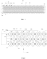
- FIG.1 is an overall structural schematic diagram of an electrical connection assembly according to an embodiment of the present application
- FIG.2 is a partially enlarged structural schematic diagram of an electrical connection assembly according to an embodiment of the present application.
- an electrical connection assembly 100 of the embodiment of the present application includes a plurality of electrical connection bodies corresponding to a plurality of cell groups of a battery module in a one-to-one relationship, and configured to electrically connect the plurality of cell groups, e.g. in series.
- the cell group includes a plurality of single cells, and an anode electrode and a cathode electrode of the single cell are arranged on a same one side thereof.
- the electrical connection body is provided with a plurality of electrical connection portions (for example, a plurality of electrical connection portions 111 for cathode electrode and a plurality of electrical connection portions 112 for anode electrode).
- the plurality of electrical connection portions are respectively connected with the electrodes of a plurality of single cells.
- Each of a plurality of conductive portions 113 is formed between adjacent electrical connection portions.
- the plurality of conductive portions 113 of the electrical connection body have a same length and a same cross-sectional area taken along a direction perpendicular to a length direction X.
- This embodiment provides a technical solution where the plurality of conductive portions 113 have the same length and the same cross-sectional area taken along the direction perpendicular to the length direction X, so that the plurality of conductive portions 113 of each electrical connection body have same internal resistances, and thus each single cell has same voltage. As a result, this lowers voltage difference between the single cells, and reduces workload of information processing of BMS and workload of backend detection.
- the electrical connection body may also be referred to as a bus bar.
- the electrical connection body is made of a sheet-like conductive material with a specific thickness.
- the electrical connection portion and the conductive portion 113 are integrated into one piece.
- a plurality of electrical connection portions and conductive portions 113 can be formed by several through holes 1112 being opened on the sheet-like conducting material.
- a plurality of electrical connection portions and conductive portions 113 can be formed by cutting the sheet-shaped conductive material in a predetermined manner.
- the conductive material of the electrical connection body may be, for example, copper, aluminum, nickel, or the like.
- the electrical connection body is provided with a plurality of electrical connection portions 112 for anode electrode and a plurality of electrical connection portions 111 for cathode electrode.
- the electrical connection portion 112 is configured to connect with the anode electrode of the single cell of one of the cell groups
- the electrical connection portion 111 for cathode electrode is configured to connect with the cathode electrode of the single cell of another of the cell groups.
- the electrical connection portion 112 for anode electrode of one of the electrical connection bodies extends into the electrical connection portion for cathode electrode of another adjacent electrical connection body; or the electrical connection portion 111 for cathode electrode of one of the electrical connection bodies extends into the electrical connection portion for anode electrode of another adjacent electrical connection body.
- an opening is provided in a middle of the electrical connection portion 111 for cathode electrode, and the anode electrode of the cell is arranged corresponding to the opening; and the electrical connection portion 111 for cathode electrode of another electrical connection body can be accommodated in the opening, and can be electrically connected to the anode electrode of single cell.
- the single cell in this embodiment may be a cylindrical cell whose anode electrode and cathode electrode are arranged on the same one side thereof.
- the anode electrode is located at a center of an upper end of the single cell
- the cathode electrode is located at a periphery of the anode electrode and at a higher level than the cathode electrode. Since the electrical connection body is provided with the electrical connection portion 112 for anode electrode and the electrical connection portion 111 for cathode electrode, the plurality of cells can be electrically connected on the same side and at the upper end of the single cell.
- the shape of the electrical connection portion 112 for anode electrode can be arranged to match with the structure feature of the anode electrode of the cell.
- the electrical connection portion 112 for anode electrode has an annular sheet-like structure which can integrally attach onto the anode electrode at the center of the cell end.
- the shape of the electrical connection portion 111 for cathode electrode can be arranged to match with the cathode electrode of the cell.
- the electrical connection portion 111 for cathode electrode has an annular sheet-like structure, and a hollow portion 1111 is formed in the annular sheet-like structure and has an inner diameter larger than an outer diameter of the electrical connection portion 112 for anode electrode. This enables the electrical connection portion 112 for anode electrode to be accommodated in the hollow portion 1111, such that both the electrical connection portion 112 for anode electrode and the electrical connection portion 111 for cathode electrode can be stably connected to the upper end of the cell.
- the electrical connection body includes a preset number of electrical connection portions arranged respectively at locations corresponding to a plurality of vertices of the polygon.
- the plurality of electrical connection bodies are arranged along a same plane into a rectangular structure, and the rectangular structure is composed of several polygons.
- the different electrical connection bodies can be formed into polygons of different shape.
- the rectangular structure can be combined by several polygons of different shape.
- the plurality of electrical connection bodies can be combined into a rectangle, the plurality of conductive portions 113 can have the same length, which improves the energy density of the battery module, and ensures a flexible layout and stability of the electrical connection assembly 100.
- the electrical connection body includes at least five electrical connecting portions, and the at least five electrical connection portions can be connected by the conductive portion 113 to form a structure similar to a quadrangle or a hexagon.
- two adjacent cell groups are arranged in a first area and a second area respectively, the plurality of electrical connection portions for anode electrode 112 of the electrical connection body are arranged in the first area, and the plurality of electrical connection portions 111 for cathode electrode are arranged in the second area.
- the plurality of electrical connection portions 112 for anode electrode in the first area are arranged respectively at locations corresponding to a plurality of vertices of a first polygon 120, and the plurality of electrical connection portions 111 for cathode electrode in the second area are arranged respectively at locations corresponding to a plurality of vertices of a second polygon 130.
- the first polygon 120 has a same shape with the second polygon 130, or has a different shape from the second polygon 130.
- the first polygon 120 can have a quadrilateral structure.
- the first polygon 120 can be an isosceles trapezoid.
- the five electrical connection portions 111 are connected by the conductive portions 113 to form a shape similar to five-ring pattern.
- the second polygon 130 can have a hexagonal structure.
- the hexagonal structure is composed of two isosceles triangles whose vertices are connected and whose base sides are opposite to each other and are parallel to each other.
- the base sides of the two isosceles triangles are parallel to a length direction X of the battery module, and two parallel sides of the quadrilateral are inclined with respect to the length direction X of the battery module.
- the number of electrical connection portions in the electrical connection body can also be less than five or more than five; and the polygons can also be triangles, quadrilaterals, or shapes with more than six sides.
- the battery module may include at least two paratactic groups. For example, there are a first group 101 and a second group 102 respectively at either side of a horizontal dotted line in FIG. 1 ; and each cell group is composed of five cells in parallel.
- a plurality of cell groups are arranged in sequence in the length direction X of the battery module, several cells in the plurality of cell groups are arranged in a form of three rows in a width direction Y of the battery module, and the cells in the adjacent rows are displaced from each other in the width direction Y That is, each cell in one row is located in the width direction Y at a location corresponding to a middle part of another adjacent row of cells.
- FIG.3 is a structural schematic diagram of an electrical connection body of an electrical connection assembly according to an embodiment of the present application.
- FIG.4 is a structural schematic diagram of another electrical connection body of an electrical connection assembly according to an embodiment of the present application.
- first electrical connection bodies 110a and second electrical connection bodies 110b alternate in the length direction X of the battery module, wherein at least two second electrical connection bodies 110b are arranged between every two first electrical connection bodies 110a. That is, the first polygons 120 and the second polygons 130 alternate in the length direction of the battery module, wherein at least two first polygons 120 are arranged between every two second polygons 130.
- first polygon 120 is a quadrilateral and the second polygon 130 is a hexagon
- two quadrilaterals are arranged between every two hexagons, and short sides of the two quadrilaterals are arranged opposite to each other, and long sides of the two quadrilaterals are arranged adjacent to each other.
- a plurality of electrical connection bodies can connect the cell groups in series along the length direction of the battery module, and a single electrical connection body can connect a plurality of single cells in the corresponding cell groups in parallel.
- the cell group when the cell group includes at least five cells, at least three connection branches are drawn out from the plurality of electrical connection portions of the electrical connection body. And, the at least three connection branches respectively extend along the three rows of cells, two of which are provided with at least two electrical connection portions, and a remaining one of which is provided with at least one electrical connection portion.
- each cell group includes five cells; the first polygon 120 may be an inclined isosceles trapezoid.
- Three connection branches can be drawn out from three electrical connection portions when being in the isosceles trapezoid.
- the three electrical connection portions are respectively arranged corresponding to the three rows of cells.
- the three connection branches respectively extend along the three rows of cells, two of which are provided with two spaced apart electrical connection portions, and a remaining one of which is provided with one electrical connection portion.
- the positions of the three connection branches can be exchanged with each other according to the shape of the electrical connection body corresponding to another cell group.
- the first group 101 and the second group 102 of the battery module are arranged in parallel.
- the first group 101 and the second group 102 are connected at one lateral end of the battery module by an electrical connector 160.
- a primary anode electrode 150 and a primary cathode electrode 140 are formed at the other lateral ends of the battery module.
- the primary anode electrode 150 is connected with the electrical connection portion 112 for anode electrode of the electrical connection body, and the primary cathode 140 is connected with the electrical connection portion 111 for cathode electrode of the electrical connection body.
- the battery module includes a set number of cell groups, for example, 36 cell groups in which the first group 101 and the second group 102 respectively include 18 cell groups. It should be noted that the above number of cell groups is discussed only for illustration, and this application does not limit the number of cell groups.
- the electrical connection portion of the electrical connection body is formed with a connection surface that is fixed with the electrode of the single cell, which can effectively increase the connection area, thereby allowing a larger current to pass through, so that the solution of the present application can be adapted to 4C quick charging solution in the related art.
- connection surface can be connected the electrode of the single cell by welding or alternatively by conductive glue.
- FIG. 5 is a partial structural three-dimensional structure view of an electrical connection assembly according to an embodiment of the present application.
- the electrical connection body includes a first connection surface for forming the electrical connection portion 112 for anode electrode and a second connection surface for forming the electrical connection portion 111 for cathode electrode.
- the electrical connection portion 112 for anode electrode and the electrical connection portion 111 for cathode electrode are connected by a bending portion 114.
- the bending portion 114 can be inclined relative to the height direction of the battery module, which can further increase the area for connecting the first connection surface and the second connection surface.
- the electrical connection assembly 100 of the battery module according to the embodiment of the present application is described above. Accordingly, the present application also provides a battery module including a plurality of cell groups connected by the electrical connection assembly 100.
- the electrical connection assembly 100 includes a plurality of electrical connection bodies corresponding to a plurality of cell groups of the battery module in a one-to-one relationship, and configured to electrically connect the plurality of cell groups.
- the cell group includes a plurality of single cells, an anode electrode and a cathode electrode of the single cell are arranged on a same one side thereof.
- the electrical connection body is provided with a plurality of electrical connection portions.
- the plurality of electrical connection portions are respectively connected with the electrodes of a plurality of single cells.
- Each of a plurality of conductive portions 113 is formed between adjacent electrical connection portions.
- the plurality of conductive portions 113 of the electrical connection body have a same length and a same cross-sectional area taken along a direction perpendicular to a length direction.
- This embodiment provides a solution in which the plurality of conductive portions 113 have the same length and the same cross-sectional area taken along the direction perpendicular to the length direction, so that the plurality of conductive portions 113 of each electrical connection body have the same internal resistances, and thus each single cell has the same voltage. As a result, this lowers voltage difference between the single cells, and reduces workload of information processing of BMS and workload of backend detection for charging or discharging of the battery module.
- the present application also provides a vehicle including the battery module as described in the above embodiments.
- the battery module and its electrical connection assembly 100 can be referred to the descriptions in the above-mentioned embodiments, and will not be repeated herein.
Landscapes
- Chemical & Material Sciences (AREA)
- Chemical Kinetics & Catalysis (AREA)
- Electrochemistry (AREA)
- General Chemical & Material Sciences (AREA)
- Engineering & Computer Science (AREA)
- Aviation & Aerospace Engineering (AREA)
- Inorganic Chemistry (AREA)
- Battery Mounting, Suspending (AREA)
- Connection Of Batteries Or Terminals (AREA)
Applications Claiming Priority (1)
| Application Number | Priority Date | Filing Date | Title |
|---|---|---|---|
| CN202210562903.3A CN114824669B (zh) | 2022-05-23 | 2022-05-23 | 电池模组的电连接组件、电池模组及车辆 |
Publications (2)
| Publication Number | Publication Date |
|---|---|
| EP4283774A2 true EP4283774A2 (de) | 2023-11-29 |
| EP4283774A3 EP4283774A3 (de) | 2024-03-20 |
Family
ID=82518127
Family Applications (1)
| Application Number | Title | Priority Date | Filing Date |
|---|---|---|---|
| EP22217204.1A Pending EP4283774A3 (de) | 2022-05-23 | 2022-12-29 | Elektrische verbindungsanordnung für batteriemodul, batteriemodul und fahrzeug |
Country Status (2)
| Country | Link |
|---|---|
| EP (1) | EP4283774A3 (de) |
| CN (1) | CN114824669B (de) |
Family Cites Families (12)
| Publication number | Priority date | Publication date | Assignee | Title |
|---|---|---|---|---|
| DE102007017024B3 (de) * | 2007-04-11 | 2008-09-25 | Daimler Ag | Batteriezelle und Verfahren zu ihrer Herstellung und Batterie |
| CN201936935U (zh) * | 2010-05-31 | 2011-08-17 | 比亚迪股份有限公司 | 一种电池隔圈、电芯保护结构及动力电池 |
| CN104347829B (zh) * | 2013-07-29 | 2019-06-14 | 深圳市比克动力电池有限公司 | 集成电芯模块 |
| CN105428585B (zh) * | 2015-12-18 | 2017-10-24 | 力神动力电池系统有限公司 | 一种锂离子电池模组 |
| US20180069212A1 (en) * | 2016-09-07 | 2018-03-08 | Thunder Power New Energy Vehicle Development Company Limited | Battery system housing with bonded rib fixation |
| CN206271772U (zh) * | 2016-12-25 | 2017-06-20 | 惠州市亿能电子有限公司 | 一种平躺式的方形电池模组 |
| CN108461669A (zh) * | 2017-12-14 | 2018-08-28 | 南京创源天地动力科技有限公司 | 一种圆柱电池组的安装结构 |
| WO2019164974A1 (en) * | 2018-02-20 | 2019-08-29 | Nio Usa, Inc. | Uniform current density tapered busbar |
| CN114041232B (zh) * | 2021-03-01 | 2024-04-12 | 深圳汝原科技有限公司 | 电芯组件、电池模组及手持式电器设备 |
| CN215496959U (zh) * | 2021-04-14 | 2022-01-11 | 一汽解放汽车有限公司 | 电池模组 |
| CN113937411B (zh) * | 2021-09-30 | 2023-07-14 | 蜂巢能源科技有限公司 | 圆柱电池模组 |
| CN114447528B (zh) * | 2022-02-28 | 2025-11-28 | 中创新航科技集团股份有限公司 | 一种汇流排及电池组 |
-
2022
- 2022-05-23 CN CN202210562903.3A patent/CN114824669B/zh active Active
- 2022-12-29 EP EP22217204.1A patent/EP4283774A3/de active Pending
Also Published As
| Publication number | Publication date |
|---|---|
| CN114824669A (zh) | 2022-07-29 |
| EP4283774A3 (de) | 2024-03-20 |
| CN114824669B (zh) | 2024-04-30 |
Similar Documents
| Publication | Publication Date | Title |
|---|---|---|
| JP7128287B2 (ja) | エネルギー密度が向上した構造を有するバッテリーモジュール、それを含むバッテリーパック及び自動車 | |
| EP1812982B1 (de) | Sekundärbatteriepack mit anordnung zu alternativer ausrichtung | |
| EP1689009A1 (de) | Batteriestapel | |
| KR102792413B1 (ko) | 버스바를 구비한 배터리 모듈, 및 배터리 팩, 및 자동차 | |
| US12244033B2 (en) | Battery pack, electronic device and vehicle | |
| US12394869B2 (en) | Battery module, battery pack comprising the same, and vehicle | |
| EP4243186A1 (de) | Sammelschiene, batteriezellenerfassungsanordnung und batteriemodul | |
| WO2019219085A1 (zh) | 电池模组和具有其的用于车辆的电池包 | |
| EP2816629A1 (de) | Energiespeicherzelle | |
| KR20260005129A (ko) | 배터리모듈 | |
| CN115066797A (zh) | 电池模块和电池组 | |
| EP4283774A2 (de) | Elektrische verbindungsanordnung für batteriemodul, batteriemodul und fahrzeug | |
| US11394087B2 (en) | Battery module | |
| CN115066799A (zh) | 电池模块和电池组 | |
| EP4672923A2 (de) | Rückseitenkontaktierte solarzelle und fotovoltaisches modul | |
| KR20200072406A (ko) | 전지 모듈 | |
| KR20220089427A (ko) | 결합 및 접속 구조가 개선된 배터리 모듈 | |
| US20240072396A1 (en) | Battery module | |
| CN110492049A (zh) | 电池和电池组 | |
| CN217719795U (zh) | 一种电池模组及电池包 | |
| CN219917496U (zh) | 电池和用电设备 | |
| CN221239750U (zh) | 电芯组件及电池模组 | |
| CN222581449U (zh) | 一种导电排、电池模组及电池包 | |
| CN223651589U (zh) | 电池连接片、电池模组及电池包 | |
| CN221150253U (zh) | 电池单元及其采集装置和电池模组 |
Legal Events
| Date | Code | Title | Description |
|---|---|---|---|
| PUAI | Public reference made under article 153(3) epc to a published international application that has entered the european phase |
Free format text: ORIGINAL CODE: 0009012 |
|
| STAA | Information on the status of an ep patent application or granted ep patent |
Free format text: STATUS: THE APPLICATION HAS BEEN PUBLISHED |
|
| AK | Designated contracting states |
Kind code of ref document: A2 Designated state(s): AL AT BE BG CH CY CZ DE DK EE ES FI FR GB GR HR HU IE IS IT LI LT LU LV MC ME MK MT NL NO PL PT RO RS SE SI SK SM TR |
|
| PUAL | Search report despatched |
Free format text: ORIGINAL CODE: 0009013 |
|
| AK | Designated contracting states |
Kind code of ref document: A3 Designated state(s): AL AT BE BG CH CY CZ DE DK EE ES FI FR GB GR HR HU IE IS IT LI LT LU LV MC ME MK MT NL NO PL PT RO RS SE SI SK SM TR |
|
| RIC1 | Information provided on ipc code assigned before grant |
Ipc: H01M 50/516 20210101ALI20240212BHEP Ipc: H01M 50/509 20210101ALI20240212BHEP Ipc: H01M 50/505 20210101ALI20240212BHEP Ipc: H01M 50/503 20210101AFI20240212BHEP |
|
| STAA | Information on the status of an ep patent application or granted ep patent |
Free format text: STATUS: REQUEST FOR EXAMINATION WAS MADE |
|
| 17P | Request for examination filed |
Effective date: 20240802 |
|
| RBV | Designated contracting states (corrected) |
Designated state(s): AL AT BE BG CH CY CZ DE DK EE ES FI FR GB GR HR HU IE IS IT LI LT LU LV MC ME MK MT NL NO PL PT RO RS SE SI SK SM TR |