EP2816629A1 - Energiespeicherzelle - Google Patents
Energiespeicherzelle Download PDFInfo
- Publication number
- EP2816629A1 EP2816629A1 EP20130161560 EP13161560A EP2816629A1 EP 2816629 A1 EP2816629 A1 EP 2816629A1 EP 20130161560 EP20130161560 EP 20130161560 EP 13161560 A EP13161560 A EP 13161560A EP 2816629 A1 EP2816629 A1 EP 2816629A1
- Authority
- EP
- European Patent Office
- Prior art keywords
- energy storage
- housing
- storage cells
- surface portion
- storage cell
- Prior art date
- Legal status (The legal status is an assumption and is not a legal conclusion. Google has not performed a legal analysis and makes no representation as to the accuracy of the status listed.)
- Withdrawn
Links
- 238000004146 energy storage Methods 0.000 title claims abstract description 309
- 210000000352 storage cell Anatomy 0.000 title claims abstract description 257
- 230000002093 peripheral effect Effects 0.000 claims description 42
- 239000012530 fluid Substances 0.000 claims description 35
- 239000012777 electrically insulating material Substances 0.000 claims description 7
- 235000015110 jellies Nutrition 0.000 description 31
- 239000008274 jelly Substances 0.000 description 31
- 210000004027 cell Anatomy 0.000 description 17
- 238000010438 heat treatment Methods 0.000 description 11
- 238000000576 coating method Methods 0.000 description 6
- 238000001816 cooling Methods 0.000 description 6
- 230000008878 coupling Effects 0.000 description 6
- 238000010168 coupling process Methods 0.000 description 6
- 238000005859 coupling reaction Methods 0.000 description 6
- 238000000926 separation method Methods 0.000 description 6
- 239000011248 coating agent Substances 0.000 description 5
- 238000003860 storage Methods 0.000 description 5
- 239000012809 cooling fluid Substances 0.000 description 4
- 230000000694 effects Effects 0.000 description 4
- 229920001971 elastomer Polymers 0.000 description 4
- 239000007788 liquid Substances 0.000 description 4
- 230000008901 benefit Effects 0.000 description 3
- 238000010586 diagram Methods 0.000 description 3
- 238000004519 manufacturing process Methods 0.000 description 3
- 229910052751 metal Inorganic materials 0.000 description 3
- 239000002184 metal Substances 0.000 description 3
- 238000003466 welding Methods 0.000 description 3
- RYGMFSIKBFXOCR-UHFFFAOYSA-N Copper Chemical compound [Cu] RYGMFSIKBFXOCR-UHFFFAOYSA-N 0.000 description 2
- 239000004411 aluminium Substances 0.000 description 2
- 229910052782 aluminium Inorganic materials 0.000 description 2
- XAGFODPZIPBFFR-UHFFFAOYSA-N aluminium Chemical compound [Al] XAGFODPZIPBFFR-UHFFFAOYSA-N 0.000 description 2
- 238000003491 array Methods 0.000 description 2
- 239000003990 capacitor Substances 0.000 description 2
- 229910052802 copper Inorganic materials 0.000 description 2
- 239000010949 copper Substances 0.000 description 2
- 230000006378 damage Effects 0.000 description 2
- 238000009826 distribution Methods 0.000 description 2
- 239000000806 elastomer Substances 0.000 description 2
- 239000000463 material Substances 0.000 description 2
- 239000004033 plastic Substances 0.000 description 2
- 238000005476 soldering Methods 0.000 description 2
- HBBGRARXTFLTSG-UHFFFAOYSA-N Lithium ion Chemical compound [Li+] HBBGRARXTFLTSG-UHFFFAOYSA-N 0.000 description 1
- 230000004075 alteration Effects 0.000 description 1
- 238000004040 coloring Methods 0.000 description 1
- 229920001940 conductive polymer Polymers 0.000 description 1
- 239000004020 conductor Substances 0.000 description 1
- 230000003292 diminished effect Effects 0.000 description 1
- 239000013013 elastic material Substances 0.000 description 1
- 239000011796 hollow space material Substances 0.000 description 1
- 238000009413 insulation Methods 0.000 description 1
- 230000002427 irreversible effect Effects 0.000 description 1
- 239000004922 lacquer Substances 0.000 description 1
- 229910001416 lithium ion Inorganic materials 0.000 description 1
- 238000000034 method Methods 0.000 description 1
- 238000012986 modification Methods 0.000 description 1
- 230000004048 modification Effects 0.000 description 1
- 230000008439 repair process Effects 0.000 description 1
- 230000009528 severe injury Effects 0.000 description 1
- 230000035939 shock Effects 0.000 description 1
- 229910000679 solder Inorganic materials 0.000 description 1
- 230000006641 stabilisation Effects 0.000 description 1
- 238000011105 stabilization Methods 0.000 description 1
- 239000000126 substance Substances 0.000 description 1
- 239000013598 vector Substances 0.000 description 1
- 239000011800 void material Substances 0.000 description 1
- 239000002699 waste material Substances 0.000 description 1
Images


Classifications
-
- H—ELECTRICITY
- H01—ELECTRIC ELEMENTS
- H01M—PROCESSES OR MEANS, e.g. BATTERIES, FOR THE DIRECT CONVERSION OF CHEMICAL ENERGY INTO ELECTRICAL ENERGY
- H01M10/00—Secondary cells; Manufacture thereof
- H01M10/60—Heating or cooling; Temperature control
- H01M10/64—Heating or cooling; Temperature control characterised by the shape of the cells
- H01M10/647—Prismatic or flat cells, e.g. pouch cells
-
- H—ELECTRICITY
- H01—ELECTRIC ELEMENTS
- H01M—PROCESSES OR MEANS, e.g. BATTERIES, FOR THE DIRECT CONVERSION OF CHEMICAL ENERGY INTO ELECTRICAL ENERGY
- H01M50/00—Constructional details or processes of manufacture of the non-active parts of electrochemical cells other than fuel cells, e.g. hybrid cells
- H01M50/20—Mountings; Secondary casings or frames; Racks, modules or packs; Suspension devices; Shock absorbers; Transport or carrying devices; Holders
- H01M50/296—Mountings; Secondary casings or frames; Racks, modules or packs; Suspension devices; Shock absorbers; Transport or carrying devices; Holders characterised by terminals of battery packs
-
- H—ELECTRICITY
- H01—ELECTRIC ELEMENTS
- H01G—CAPACITORS; CAPACITORS, RECTIFIERS, DETECTORS, SWITCHING DEVICES, LIGHT-SENSITIVE OR TEMPERATURE-SENSITIVE DEVICES OF THE ELECTROLYTIC TYPE
- H01G11/00—Hybrid capacitors, i.e. capacitors having different positive and negative electrodes; Electric double-layer [EDL] capacitors; Processes for the manufacture thereof or of parts thereof
- H01G11/10—Multiple hybrid or EDL capacitors, e.g. arrays or modules
-
- H—ELECTRICITY
- H01—ELECTRIC ELEMENTS
- H01G—CAPACITORS; CAPACITORS, RECTIFIERS, DETECTORS, SWITCHING DEVICES, LIGHT-SENSITIVE OR TEMPERATURE-SENSITIVE DEVICES OF THE ELECTROLYTIC TYPE
- H01G11/00—Hybrid capacitors, i.e. capacitors having different positive and negative electrodes; Electric double-layer [EDL] capacitors; Processes for the manufacture thereof or of parts thereof
- H01G11/78—Cases; Housings; Encapsulations; Mountings
-
- H—ELECTRICITY
- H01—ELECTRIC ELEMENTS
- H01M—PROCESSES OR MEANS, e.g. BATTERIES, FOR THE DIRECT CONVERSION OF CHEMICAL ENERGY INTO ELECTRICAL ENERGY
- H01M50/00—Constructional details or processes of manufacture of the non-active parts of electrochemical cells other than fuel cells, e.g. hybrid cells
- H01M50/10—Primary casings; Jackets or wrappings
- H01M50/102—Primary casings; Jackets or wrappings characterised by their shape or physical structure
- H01M50/103—Primary casings; Jackets or wrappings characterised by their shape or physical structure prismatic or rectangular
-
- H—ELECTRICITY
- H01—ELECTRIC ELEMENTS
- H01M—PROCESSES OR MEANS, e.g. BATTERIES, FOR THE DIRECT CONVERSION OF CHEMICAL ENERGY INTO ELECTRICAL ENERGY
- H01M50/00—Constructional details or processes of manufacture of the non-active parts of electrochemical cells other than fuel cells, e.g. hybrid cells
- H01M50/20—Mountings; Secondary casings or frames; Racks, modules or packs; Suspension devices; Shock absorbers; Transport or carrying devices; Holders
- H01M50/204—Racks, modules or packs for multiple batteries or multiple cells
- H01M50/207—Racks, modules or packs for multiple batteries or multiple cells characterised by their shape
- H01M50/209—Racks, modules or packs for multiple batteries or multiple cells characterised by their shape adapted for prismatic or rectangular cells
-
- H—ELECTRICITY
- H01—ELECTRIC ELEMENTS
- H01M—PROCESSES OR MEANS, e.g. BATTERIES, FOR THE DIRECT CONVERSION OF CHEMICAL ENERGY INTO ELECTRICAL ENERGY
- H01M50/00—Constructional details or processes of manufacture of the non-active parts of electrochemical cells other than fuel cells, e.g. hybrid cells
- H01M50/20—Mountings; Secondary casings or frames; Racks, modules or packs; Suspension devices; Shock absorbers; Transport or carrying devices; Holders
- H01M50/262—Mountings; Secondary casings or frames; Racks, modules or packs; Suspension devices; Shock absorbers; Transport or carrying devices; Holders with fastening means, e.g. locks
- H01M50/264—Mountings; Secondary casings or frames; Racks, modules or packs; Suspension devices; Shock absorbers; Transport or carrying devices; Holders with fastening means, e.g. locks for cells or batteries, e.g. straps, tie rods or peripheral frames
-
- H—ELECTRICITY
- H01—ELECTRIC ELEMENTS
- H01M—PROCESSES OR MEANS, e.g. BATTERIES, FOR THE DIRECT CONVERSION OF CHEMICAL ENERGY INTO ELECTRICAL ENERGY
- H01M50/00—Constructional details or processes of manufacture of the non-active parts of electrochemical cells other than fuel cells, e.g. hybrid cells
- H01M50/50—Current conducting connections for cells or batteries
- H01M50/502—Interconnectors for connecting terminals of adjacent batteries; Interconnectors for connecting cells outside a battery casing
- H01M50/509—Interconnectors for connecting terminals of adjacent batteries; Interconnectors for connecting cells outside a battery casing characterised by the type of connection, e.g. mixed connections
-
- Y—GENERAL TAGGING OF NEW TECHNOLOGICAL DEVELOPMENTS; GENERAL TAGGING OF CROSS-SECTIONAL TECHNOLOGIES SPANNING OVER SEVERAL SECTIONS OF THE IPC; TECHNICAL SUBJECTS COVERED BY FORMER USPC CROSS-REFERENCE ART COLLECTIONS [XRACs] AND DIGESTS
- Y02—TECHNOLOGIES OR APPLICATIONS FOR MITIGATION OR ADAPTATION AGAINST CLIMATE CHANGE
- Y02E—REDUCTION OF GREENHOUSE GAS [GHG] EMISSIONS, RELATED TO ENERGY GENERATION, TRANSMISSION OR DISTRIBUTION
- Y02E60/00—Enabling technologies; Technologies with a potential or indirect contribution to GHG emissions mitigation
- Y02E60/10—Energy storage using batteries
-
- Y—GENERAL TAGGING OF NEW TECHNOLOGICAL DEVELOPMENTS; GENERAL TAGGING OF CROSS-SECTIONAL TECHNOLOGIES SPANNING OVER SEVERAL SECTIONS OF THE IPC; TECHNICAL SUBJECTS COVERED BY FORMER USPC CROSS-REFERENCE ART COLLECTIONS [XRACs] AND DIGESTS
- Y02—TECHNOLOGIES OR APPLICATIONS FOR MITIGATION OR ADAPTATION AGAINST CLIMATE CHANGE
- Y02T—CLIMATE CHANGE MITIGATION TECHNOLOGIES RELATED TO TRANSPORTATION
- Y02T10/00—Road transport of goods or passengers
- Y02T10/60—Other road transportation technologies with climate change mitigation effect
- Y02T10/70—Energy storage systems for electromobility, e.g. batteries
Definitions
- the present invention relates to the field of energy storage cells and to energy storage systems comprising a plurality of energy storage cells.
- the invention relates to an energy storage cell for an electrically driven vehicle, a stationary storage system, an uninterruptible power supply (UPS) or for other purposes.
- UPS uninterruptible power supply
- an energy storage cell comprises an electric energy source, such as e.g. an electrochemical generator, which may e.g. be in the shape of a jelly roll that includes one or more anode and cathode layers rolled up with a separator layer in between. Accordingly, energy storage cells are often of cylindrical shape.
- an electric energy source such as e.g. an electrochemical generator
- the energy storage cells are commonly contacted at an end face of the jelly rolls.
- at most one electrical contact is placed on a circumferential section of a housing of the energy storage cell.
- pouch-/coffee-bag there are three known types of energy storage cell designs: pouch-/coffee-bag, cylindrical and prismatic.
- batteries having energy storage cell arrays with plan view outlines in the form of equilateral triangles, regular pentahedra or regular hexahedra are known, e.g. from US 4,707,420 A .
- the anodes and cathodes of neighbouring cells are connected by providing a wiring at an end face of each cell.
- DE 10 2009 022 678 Al discloses a battery cell having a prismatic housing.
- the housing has a hexagonal base area and is made of a metal plate. Still, to be able to electrically connect neighbouring cells, an electrical coupling must be provided at the end face of each cell.
- the invention solves this problem by providing the energy storage cell according to claim 1 and the energy storage system according to claim 11. Preferred embodiments are described in the depending claims.
- an energy storage cell comprising an electric energy source and a housing, the electric energy source being arranged in the housing and having an anode and a cathode.
- the housing comprises a circumferential section and two opposing end sections, the circumferential section defining a lateral area of the housing and the end sections defining base areas of the housing.
- the lateral area comprises at least a first electrically conductive surface portion and a second electrically conductive surface portion, the first and the second surface portions being electrically isolated from each other.
- the first surface portion is electrically coupled to the anode of the electric energy source and the second surface portion is electrically coupled to the cathode of the electric energy source.
- the energy storage cell may easily be electrically contacted via the lateral area of the housing.
- the first and second surface portions may be partially or completely plane as described in more detail below.
- the anode refers to the negative pole of the electric energy source
- the cathode refers to the positive pole of the electric energy source.
- two adjacent energy storage cells may easily be connected to each other by arranging the energy storage cells next to each other, such that the conductive surface portions of the cells touch each other.
- the anode and the cathode of the electric energy source are coupled to surface portions of the housing, no wiring at the end faces of the energy storage cells is required.
- no extra effort and/or elements for electrical and/or mechanical connection are necessary and the assembly of a plurality of energy storage cells is facilitated.
- the energy storage cells may easily be arranged next to each other, and thereby mechanically and electrically be connected, there is e.g. no need to solder or weld the energy storage cells.
- the risk of thermal or mechanical damage of the energy storage cells during the assembly is reduced.
- a larger area may be used for conducting the electrical current from the energy storage cell during operation. Accordingly, the current density and the contact resistance are reduced, thereby reducing the heating due to the current flow and thus improving the reliability of the energy storage cell.
- the energy storage cells may easily be removed from one energy storage system and then be placed in another energy storage system. Re-use of the energy storage cells is therefore facilitated, reducing the amount of potentially harmful waste. Furthermore, the disassembling starts at cell-level and therefore at low voltages, such that safety issues are massively reduced as compared to known energy storage cell arrays.
- the energy storage cells of the present disclosure provide the following additional advantages: 1. Less material needed for electrical and mechanical connection, 2. less production expenditure, 3. because of 1. and 2.: lower complexity and lower error rate, 4. in the event of fault: sudden disconnecting is possible, hence no dangerous voltages and no thermal coupling of cells, and 5. more flexibility and no need for 60V-modules.
- the first and the second surface portions may be oriented in different directions. In this way, each of the first and the second surface portions is easily accessible without the risk of inadvertently contacting an incorrect surface portion having an unwanted polarity.
- the energy storage cell When combined with other energy storage cells, the energy storage cell may easily be rotated to adjust the polarity of the surface portion touching an adjacent energy storage cell.
- complex circuits of energy storage cells coupled in parallel and/or in series may be assembled by correctly choosing the orientation of the energy storage cells and their position within the circuit as described in more detail below.
- An orientation of surface portions in different directions may, e.g. comprise that the normal vectors on the first and second surface portions are pointing in different directions.
- first and the second surface portions may be arranged on opposite sides of the circumferential section. This allows for a large spatial separation between them.
- first surface portion and the second surface portion have an equally large surface area. Hence, the current density would be equal in operation.
- the first and the second surface portion may be symmetrically arranged over the lateral area of the housing. In this embodiment, the first and the second surface portions are equally accessible.
- the electric energy source may, in some embodiments, comprise an electrochemical generator.
- the electrochemical generator may e.g. include an electrochemical converter for converting electrical energy to chemical energy and vice versa and an electrochemical storage. Additionally or alternatively, the electric energy source may comprise other storage means or sources of electric energy, such as a capacitor.
- the electric energy source comprises a jelly roll.
- a jelly roll is a stack of at least an anode, a separator layer and a cathode which are rolled up. In some embodiments, the housing completely surrounds the electric energy source.
- the housing extends along a longitudinal axis.
- the base areas may extend transversely, in particular perpendicularly to the longitudinal axis.
- the lateral area may extend around the longitudinal axis.
- the housing may, e.g. have the shape of a column.
- a length of the housing measured between the base areas may be larger than a diameter of the circumferential section.
- the length of the housing may be larger than twice, in particular larger than three times and preferably larger than four times the diameter of the circumferential section.
- the base areas may be opposite each other, i.e. the base areas may be located at opposite ends of the housing. In some embodiments, the base areas are parallel to each other. Alternatively or additionally, the base areas may be plane. This allows two or more energy storage cells to be stacked one upon the other as described in more detail below. Alternatively or additionally, the base areas may be equal in size. One or both of the base areas may enclose a right angle with the lateral area.
- the housing is in the shape of a cylinder or of a truncated cone.
- the base areas are base areas of the cylinder or the truncated cone, respectively, and the lateral area is a circumferential area of the cylinder or the truncated cone, respectively.
- the lateral area of the housing comprises a number of lateral facets with adjacent lateral facets being separated by lateral edges of the housing. Providing edges on the lateral area allows for an easy identification of different lateral facets, possibly being coupled to different poles of the electric energy source, i.e. to the anode or the cathode.
- the lateral facets are plane. This allows a good contact between lateral facets of adjacent energy storage cells in an energy storage system.
- the lateral facets may be generally plane and may have a surface structure comprising protrusions and/or recesses as described in more detail below.
- the housing may be in the shape of a polyhedron, in particular, a prismatoid. In some specific embodiments, the housing may be in the shape of a truncated pyramid, with each of the base areas defining a polygon with n corners (n>2).
- the housing is in the shape of a prism.
- the base areas of the housing correspond to base areas of the prism and the lateral area corresponds to a lateral area, i.e. a circumferential area, of the prism comprising a number of lateral facets separated by lateral edges as described above.
- a prism provides equally sized and shaped base areas.
- the prism may, e.g., be a right prism, i.e. the base areas and the lateral area may join at right angles, which facilitates the assembly of a large number of energy storage cells.
- the prism is a regular prism. In a regular prism, the lateral facets are of the same size and shape. This allows for an easier assembly and for an improved current distribution over the lateral area.
- the housing may, in particular, be in the shape of a hexagonal prism, preferably, a regular hexagonal prism.
- a number of regular hexagonal prisms may easily be assembled one next to each other to completely fill a given space.
- the first surface portion and the second surface portion extend over different lateral facets of the housing.
- the different poles of the energy storage cell may thus easily be identified by a user.
- the exterior surface area is used in an optimum way to reduce the current density and the contact resistance and thereby improving the reliability of the energy storage cell.
- each of the first and the second surface portions extends over at least two lateral facets, in particular, over at least two adjacent lateral facets.
- the first and the second surface portions each may extend over an equal number of lateral facets.
- the lateral area comprises n lateral facets, with n being an even number
- the first and the second surface portions each may extend over n/2 lateral facets, preferably n/2 adjacent facets.
- the first and/or the second surface portion may extend over an entire surface area of the one or more lateral facets.
- each of the lateral facets is part of either the first or the second surface portion.
- the lateral area comprises a third surface portion, which may e.g. be electrically insulating. This could be done e.g. by applying an insulative coating such as an insulation-lacquer on a third surface portion of the lateral area.
- a non-conductive element such as an elastomer/plastic may be put in between two adjacent energy storage cells.
- the lateral facets are plane.
- the first surface portion comprises a first surface structure defining at least one protrusion and/or at least one recess
- the second and/or the first surface portion comprises a second surface structure defining at least one recess and/or at least one protrusion, wherein the first surface structure is formed to match the second surface structure.
- the surface structures result in a larger contact area when two energy storage cells are coupled. Moreover, using appropriate surface structures may prevent an undesired assembly of energy storage cells with an incorrect polarity of adjacent energy storage cells.
- the first and/or the second surface portions may comprise a label to identify the surface portions as being coupled with the anode or the cathode of the electric energy source.
- the first and/or the second portion may be provided with a coloring. To this effect, all or a section of the first surface portion may be of a first color, such as red. Alternatively or additionally, all or a section of the second surface portion may be of a second color, such as blue. The user may thus easily identify the polarities of the energy storage cell.
- the first and the second surface portions may e.g. comprise differently colored conductive coatings.
- At least one of the end sections of the housing is made of an electrically insulating material.
- the electrically insulating material may, for example, comprise a rubber or a plastic material.
- the electrically insulating material may, in some embodiments, comprise an electrically insulating coating on the housing. In some embodiments, the electrically insulating material is pressed into an opening of the housing or is otherwise affixed to the circumferential section.
- one of the end sections is electrically conductive and is electrically coupled to the anode or the cathode of the electric energy source.
- the end sections may be electrically conductive and one of the end sections is electrically coupled to the anode of the electric energy source, while the other one of the end sections is electrically coupled to the cathode of the electric energy source.
- the energy storage cell further comprises at least one peripheral cavity formed between the electric energy source and the circumferential section of the housing, in particular, at a lateral edge of the housing.
- a cylindrical electric energy source such as a jelly roll or a rolled-up double-layer capacitor.
- the peripheral cavity may e.g. be a peripheral channel.
- the peripheral cavity may e.g. extend along a longitudinal axis of the housing.
- a peripheral cavity is formed between the electric energy source and the housing at each lateral edge of the housing. E.g., for a cylindrical electric energy source and a hexagonal housing, six peripheral cavities may be formed.
- the peripheral cavity may, in some embodiment, be used to introduce a fluid, such as a cooling or a heating fluid. Additionally or alternatively, the peripheral cavity may serve as a cushioning element in case of a crash. When the energy storage cell is compressed by a high lateral force, as e.g. during an accident, the peripheral cavity acts as a buffer to cushion the forces, such that the electric energy source and/or its casing remain undamaged.
- the peripheral cavity or the peripheral cavities may be empty or may e.g. be filled with a liquid or an elastic element.
- the peripheral cavity or the peripheral cavities help to reduce the mechanical forces upon the electric energy source. In a severe accident, the housing may be deformed. Providing peripheral cavities as described in this disclosure, even though the electric energy source may also be deformed, it is still protected against severe damage like e.g. internal short circuits.
- the energy storage cell further comprises a central cavity formed within the electric energy source.
- the central cavity may, e.g. be in the shape of a channel and/or may extend along a longitudinal axis of the housing and/or through a length of the electric energy source.
- the electric energy source may comprise a jelly roll rolled up on a spindle.
- the spindle may be hollow to form the central cavity inside.
- the spindle may also mechanically attach two or more components of the housing to each other, such as e.g. the two end sections.
- the central cavity may be used to introduce a heating or a cooling fluid. Additionally or alternatively, the central cavity may cushion the effect of a lateral thrust.
- the central cavity may be empty or may be filled with a liquid or an elastic element.
- the at least one peripheral cavity and/or the central cavity is accessible through the housing, in particular, through at least one opening in at least one of the end sections of the housing.
- This embodiment allows the introduction of a cooling fluid to cool down the electric energy source such as a jelly roll during operation.
- a heating fluid may be introduced in order to increase the temperature of the electric energy source to provide for an optimum operation temperature of the electric energy source, e.g. at the start of operation. This is, in particular, advantageous when the energy storage cell is used in cold environments.
- the at least one peripheral cavity and/or the central cavity is accessible through openings in each of the end sections, preferably in each of the base areas.
- one end section may form an inlet opening for a fluid, while the opposing end section may form an outlet opening for the fluid.
- the central cavity and/or the at least one peripheral cavity may by coupled to a fluid circuit as described in more detail below.
- an energy storage system comprising a first set of energy storage cells, each of the energy storage cells of the first set being of the aforementioned type.
- the first surface portion and/or the second surface portion of each energy storage cell of the first set is in electrical and mechanical contact with the first surface portion and/or the second surface portion of another one of the energy storage cells of the first set.
- each lateral facet of each energy storage cell of the first set is in electrical and mechanical contact with at least and/or at most one first surface portion or one second surface portion of another one of the energy storage cells of the first set.
- the energy storage cells of the first set may be arranged parallel and next to each other. The energy storage cells of the first set may e.g. all be identical.
- two or more energy storage cells of the first set may be easily put next to each other with the first and/or the second surface portions of adjacent cells touching each other. Hence, no additional wiring, welding or soldering is needed to establish an electrical and mechanical contact between the energy storage cells. By rotating the energy storage cells accordingly, two or more of the energy storage cells may be connected in parallel or in series, according to the desired electric circuit.
- an electrically conductive elastomer may be put in between the surface portions of two adjacent energy storage cells in order to even out irregularities of their surfaces.
- adjacent energy storage cells may still be soldered or welded together for mechanical stabilization.
- the energy storage system comprises a fastening element, wherein the fastening element at least partially encloses the first set of energy storage cells to keep the energy storage cells together, wherein, in particular, the fastening element applies a mechanical force on the first set of energy storage cells to press the first set of energy storage cells together.
- the fastening element may comprise a strap like, for example, a ratchet strap.
- the fastening element may comprise one or more elastic sections such as one or more springs and/or a spring form.
- the fastening element may, e.g. completely enclose the first set of energy storage cells.
- the energy storage system further comprises at least a second set of energy storage cells, each energy storage cell of the second set being of the aforementioned type.
- the second set of energy storage cells is arranged on top the first set of energy storage cells, such that one of the end sections of at least one energy storage cell of the second set is facing towards one of the end sections of one of the energy storage cells of the first set.
- the energy storage cells of the second set may be parallel and next to each other.
- the energy storage cells of the second set may all be identical and may e.g. be identical to the energy storage cells of the first set.
- At least two sets of energy storage cells may be stacked one upon the other.
- the first set and the second set may be spaced apart leaving a separation distance between the first and the second set of energy storage cells.
- an insulating layer may be placed in the separation distance.
- the energy storage cells of the second set may be arranged directly on top of the energy storage cells of the first set. In other words, the end section of a cell of the second set may touch an end section of a cell of the first set.
- the energy storage system may further comprise a third and, potentially, even more sets of energy storage cells.
- the third set of energy storage cells may be stapled on the second set of energy storage cells the same way as described for the second set being stapled on the first set.
- the energy storage system comprises more than 5, in particular more than 10 and preferably more than 15 additional sets of energy storage cells of the aforementioned type, the energy storage cells of each of the additional sets being stapled on another of the sets of energy storage cells.
- the energy storage cells of the first set are arranged such that the longitudinal axes of their housings are parallel.
- the energy storage cells of the first set may further be arranged in a same first plane, the first plane being perpendicular to the longitudinal axes of the housings of the energy storage cells of the first set.
- at least one additional set (such as a second set) of energy storage cells is arranged on top of the first set, wherein the energy storage cells of each additional set are arranged such that the longitudinal axes of their housings are parallel.
- the energy storage cells of each additional set may be arranged in a respective plane perpendicular to the longitudinal axes of the housings of the cells of that set.
- the energy storage cells of the second set may be arranged in a second plane perpendicular to the longitudinal axes of the housings of the cells of the second set.
- the planes of each set such as the first and second planes, may be parallel to each other and may, in particular, be spaced apart by a plane distance.
- the plane distance may, e.g. correspond to a height of the housing of the energy storage cells.
- the energy storage system further comprises an anode contact element and a cathode contact element, the anode contact element being in electrical contact with the first surface portion of at least one energy storage cell of the first set and the cathode contact element being in electrical contact with the second surface portion of at least one other energy storage cell of the first set.
- the anode contact element may further be in electrical contact with the first surface portion of at least one energy storage cell of at least the second set of energy storage cells
- the cathode contact element may further be in electrical contact with the second surface portion of at least one other energy storage cell of at least the second set of energy storage cells.
- the anode contact element and/or the cathode contact element may, for example, be formed of a metal such as copper or aluminium.
- the anode contact element and/or the cathode contact element may extend parallel to the longitudinal axes of the housings of the energy storage cells.
- the anode contact element and/or the cathode contact element may extend over an energy storage cell of the first set and an energy storage cell of each of the additional sets of energy storage cells such as the second set of energy storage cells.
- the anode contact element may extend over the entire first surface portion of the at least one energy storage cell. Additionally or alternatively, the cathode contact element may extend over the entire second surface portion of the at least one other energy storage cell. In some embodiments, the anode contact element and/or the cathode contact element may extend over one or more lateral facets of each of one or more energy storage cells. In some embodiments, the anode contact element and/or the cathode contact element comprises a slab or rod of metal such as aluminium or copper.
- the anode contact element and/or the cathode contact element may, e.g. have a triangular cross-section. This is, in particular, preferred for embodiments, in which an energy storage cell having the shape of a hexagonal prism is used. It is also preferred that the anode contact element and/or the cathode contact element couples to the first or the second surface portion, respectively, of at least two energy storage cells of the first and/or the second set of energy storage cells. In this embodiment, the current density at an interface between the energy storage cells and the contact element is reduced.
- At least a first energy storage cell of the first set of energy storage cells comprises at least one peripheral cavity and/or a central cavity which is accessible through the housing as specified above.
- the energy storage system may further comprise a fluid circuit coupled to the at least one peripheral cavity and/or the central cavity of the first energy storage cell of the first set of energy storage cells.
- the fluid circuit may, e.g. comprise an electrically insulating tubing.
- the fluid circuit couples the peripheral and/or the central cavities of the energy storage cells of the first set of energy storage cells in parallel and/or in series.
- the fluid circuit may couple the peripheral and/or the central cavities of the energy storage cells of the first set of energy storage cells in parallel to each other, and in series to the peripheral and/or the central cavities of the energy storage cells of the second set of energy storage cells.
- the fluid circuit may further comprise a pump to re-circulate a fluid through the fluid circuit and the at least one peripheral cavity and/or the central cavity.
- the fluid circuit comprises a fluid, i.e. a liquid or a gas.
- the fluid may, preferably, be an electrically non-conductive fluid in order to avoid unwanted shortcuts.
- the energy storage system further comprises cooling means and/or heating means thermally coupled to the fluid circuit. The cooling means and/or the heating means may be used to cool down or heat up the fluid in the fluid circuit, respectively.
- a temperature sensor may be provided in thermal contact with the fluid of the fluid circuit or the electric energy source and the energy storage system may further comprise control circuitry coupled to the cooling means and/or the heating means and the temperature sensor to keep the temperature of the fluid within the fluid circuit in a pre-defined temperature interval.
- the end sections of the energy storage cells of the energy storage system are not electrically connected.
- FIG. 1 shows an energy storage cell 100 according to an embodiment of the invention in a perspective view.
- the energy storage cell 100 comprises a prismatic housing 10.
- the housing 10 comprises a circumferential section and defines a longitudinal axis x.
- the housing 10 has a cross-section in the shape of a regular hexagon, as illustrated in more detail in Figs. 6 and 8 .
- the lateral area of the housing 10 comprises six lateral facets 21-26, which are all of the same size and shape.
- the six lateral facets 21-26 are separated by six lateral edges.
- lateral facets 24-26 are electrically coupled together to form a first electrically conductive surface portion 11.
- Another three adjacent lateral facets 21-23 are electrically coupled together to form a second electrically conductive surface portion 12.
- the lateral facets 24-26 forming the first surface portion are electrically insulated from the lateral facets 21-23 forming the second surface portion 12 by an insulating separator element 40 which extends along the housing 10
- the insulating separator element 40 may further run through the housing 10 and through the electric energy source 50.
- a jelly roll is used as electric energy source 50 having its own insulating separation layer, as described in the following.
- the energy storage cell 100 of Figures 1 , 6 and 8 further comprises a jelly roll as an electric energy source 50 (not shown in Figs. 1 and 8 ), which is arranged inside the housing 10.
- the jelly roll 50 comprises an anode and a cathode.
- the anode of the jelly roll 50 is electrically coupled to the first surface portion 11 of the housing 10, while the cathode of the jelly roll 50 is electrically coupled to the second surface portion 12 of the housing 10.
- the surface area of the first surface portion 11 is equal to the surface area of the second surface portion 12.
- the first surface portion 11 may be coated with a conductive coating of a first colour, for example red, while the second surface portion 12 may be coated with a conductive coating of a second colour, for example blue (not shown).
- the housing 10 of the energy storage cell 100 further comprises two end sections 30 and 35 defining hexagonal base areas of the housing 10.
- the end sections 30 and 35 of the housing 10 are parallel to each other and are connected by the circumferential section of the housing 10.
- the end sections 30 and 35 each comprise an electrically insulating material, such as rubber or a non-conductive polymer.
- the end sections 30, 35 may also be made of electrical conductive material and be insulated against at least one of the circumferential poles.
- an opening 31 is formed in the end section 30.
- the opening 31 is a circular opening formed in the centre of the end section 30.
- the opening 31 in the end section 30 is connected to a central cavity (or channel) running through the jelly roll 50 of the energy storage cell 100.
- the end section 35 opposing the end section 30 has a similar opening (not shown), which is also connected to the central cavity of the energy storage cell 100.
- the openings formed in the end sections 30, 35 of the housing 10 may be used as inlet and outlet openings, respectively, for a heating or a cooling fluid.
- FIG 2 shows a schematic cross-sectional view of the energy storage cell 100 shown in Figure 1 . It represents both electrically surface portions 11, 12 as well as the insulating separator element 40 in between. This illustration should help to easily demonstrate the electric and mechanic connection of several individual energy storage cells in Figures 4 and 5 .
- FIG 3 shows an electric circuit diagram of a model energy storage system that may be implemented using the energy storage cells of an embodiment of the invention, such as the energy storage cell 100 illustrated in Figs. 1 , 6 and 8 .
- two energy storage cells C are connected in parallel, forming a pair of energy storage cells with twice the capacity of a single energy storage cell.
- Three of such pairs of energy storage cells are connected in series between two nodes A and B in order to triple the overall voltage.
- Figure 4 shows a cross-sectional view through an array of six energy storage cells 100 coupled together to form the electric circuit shown in Figure 3 .
- the lateral areas of adjacent energy storage cells 100 touch each other, such that no gap is formed in between them.
- the six energy storage cells 100 are oriented and put together in a way, such that two energy storage cells 100 form a pair of energy storage cells coupled in parallel. Three of such pairs are then coupled in series.
- an anode contact element 320 is shown in Figure 4 which electrically and mechanically connects to the first surface portions 11 of two energy storage cells at node B shown in Figure 3 .
- a cathode contact element 310 is electrically and mechanically coupled to the second surface portions 12 of two different energy storage cells 100 at the other end of the array shown in Figure 4 , at the position illustrated as node A in Figure 3 .
- the anode and cathode contact elements 320, 310 each have a triangular cross section.
- An arbitrarily shaped and dimensioned space can easily be filled by flexibly putting the energy storage cells 100 together, using an appropriate number and configuration of energy storage cells 100.
- the energy storage cells 100 may easily be re-arranged to form any other circuit because of their geometry and since they are just pushed together. Additionally or alternatively, energy storage cells 100 may be added or removed from the array shown in Figure 4 .
- the invention is not limited in this way.
- other electric energy sources such as other jelly rolls may be used in the energy storage cell 100, having a different output voltage V c .
- different numbers of energy storage cells 100 may be coupled in parallel or in series to achieve other output voltages V a of an energy storage system. Generally, by connecting multiple energy storage cells in parallel, the capacity is multiplied.
- a fastening element 200 may be used as illustrated in Figure 5.
- Figure 5 shows an energy storage system 1000 similar to that shown in Figure 4 .
- another form of anode and cathode contact elements could be incorporated in the fastening element 200, e.g. by providing an electric coating (not shown) on appropriate portions of the interior surface of the fastening element 200.
- the fastening element 200 may comprise a ratchet strap or a spring form.
- the fastening element 200 is adapted to apply a mechanical force to the energy storage cells 100 of the energy storage system 1000 to press the energy storage cells 100 together. Except for the interior surface portions used to selectively contact first and second surface portions of some of the energy storage cells 100, the interior surface of the fastening element 200 may be electrically insulating.
- the fastening element 200 of the energy storage system 1000 as shown in Figure 5 completely encloses the energy storage cells 100. However, it may be understood by the skilled person that, in alternative embodiments, the fastening element 200 may only partially enclose the energy storage cells 100.
- the fastening element 200 may comprise an elastic material, such as a spring to apply the mechanical force on the energy storage cells 100.
- FIG. 6 shows a schematic cross-sectional view through an energy storage cell 100 of an embodiment of the invention.
- the space for the electric energy source i.e. the jelly roll 50 inside the housing 10 of the energy storage cell 100 is illustrated.
- the jelly roll 50 has a circular cross-section.
- the jelly roll 50 may be cylindrical.
- peripheral cavities 60 are formed between the housing 10 and the jelly roll 50.
- the peripheral cavities 60 are formed between the lateral edges of the housing 10 and the jelly roll 50.
- the peripheral cavities 60 extend along the longitudinal axis x of the housing 10 illustrated in Figs. 1 and 8 .
- the peripheral cavities 60 shown in Fig. 6 are also open at the end sections 30, 35. In these embodiments, these cavities 60 could additionally be used for climatisation or as crush elements.
- the jelly roll 50 of the energy storage cell 100 comprises a spindle 55 in the centre thereof.
- the spindle 55 may be used to roll up the anode and the cathode layers as well as separating layers of the jelly roll 50.
- the spindle 55 of the jelly roll 50 may be hollow.
- the spindle 55 encloses a hollow space forming a central cavity (or channel) 52 of the energy storage cell 100.
- the peripheral cavities 60 and the central cavity 52 may serve one or more purposes. For example, during a crash, they may function as to cushion the impact of the crash, such that damage to the jelly roll 50 is prevented or at least diminished. To this effect, the channels 60 may be empty. In some embodiments, however, a cushioning element (not shown) may be arranged in one or more of the peripheral cavities 60 and/or the central cavity 52.
- the peripheral cavities 60 are accessible through the housing 10, e.g. via openings in the circumferential section or in at least one of the end sections 30, 35.
- a fluid such as a cooling fluid or a heating fluid may be introduced into the peripheral cavities 60 to modify the temperature of the jelly roll 50.
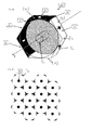
- FIG. 7 shows an energy storage system 2000 according to another embodiment of the invention.
- the energy storage system 2000 comprises 12 energy storage cells 100.
- an anode contact element 320 and a cathode contact element 310 are provided.
- Each of the contact elements 320, 310 contacts two energy storage cells 100 of the 12 energy storage cells 100 shown in Fig. 7 .
- the energy storage system comprises one or more additional sets of energy storage cells 100 on top or below the displayed set of 12 energy storage cells
- the anode and the cathode contact elements 320, 310 may also contact these additional sets of energy storage cells 100.
- the energy storage cells 100 and the anode and cathode contact elements 320, 310 are enclosed by a fastening element 300.
- the fastening element 300 shown in Figure 7 has a rectangular cross-section.
- voids 350 are formed between the energy storage cells 100 and the fastening element 300.
- the voids 350 may be filled with cushioning elements.
- the voids 350 may be left empty to serve as additional channels to introduce a cooling or heating fluid.
- Figure 8 is a perspective view to better illustrate the positioning of the central cavity 52.
- the central cavity 52 forms a channel and extends along the longitudinal axis x of the energy storage cell 100.
- the central cavity 52 may be connected to openings such as the opening 31 of the end section 30 illustrated in Figure 1 .
- a fluid may be introduced into the central cavity 52.
- the fluid may comprise a liquid or a gas to regulate a temperature of the jelly roll 50 of the energy storage cell 100.
- the energy storage system according to the invention may further comprise a fluid circuit (not shown) coupled to the central cavity 52 of the energy storage cell 10 via the openings in the end sections 30, 35.
- the fluid circuit may comprise elements such as a pump, a heating element, a heat pipe or a cooling element as may be described elsewhere in this description.
- the fluid circuit may be coupled to one or more, in particular, to all energy storage cells of the energy storage system.
- the fluid circuit may additionally or alternatively be coupled to the peripheral cavities 60 of some or all energy storage cells of the energy storage system.
- the housing 10 may comprise one or more openings connected to one or more of the peripheral cavities 60, for example openings in the end sections 30, 35 of the energy storage cell(s).
- the energy storage cells 100 of the energy storage system 2000 of Figure 7 are shown in a schematic cross-sectional view.
- the shaded areas in Figure 10 illustrate the position of the peripheral cavities 60 and the central cavities 52 of the energy storage cells 100.
- the central cavities 52 and/or the peripheral cavities 60 of some or all of the energy storage cells 100 of the energy storage system 2000 may act as cushioning spaces in case of a crash.
- the central cavities 52 and the peripheral channels 60 may cushion the jelly rolls in case of a crash even if they are filled with a fluid to control the temperature of the jelly rolls as described above.
- Figure 9 shows that the cavities are evenly distributed all over the system, which can provide a homogeneous climatisation or cushioning against mechanical shocks.
- the housing of the energy storage cell may have a different cross-section, such as a rectangular, in particular a quadratic, or an n-cornered cross-section with n ⁇ 8.
- the first and/or the second surface portion of the energy storage cell may comprise a curved surface section and/or one or more protrusions and/or recesses.
- a further set of energy storage cells may be positioned on top of a first set of energy storage cells such as the energy storage cells illustrated in Figures 5 and 7 .
- the same anode and cathode contact elements may be used to connect both sets of energy storage cells.
Landscapes
- Chemical & Material Sciences (AREA)
- Chemical Kinetics & Catalysis (AREA)
- Electrochemistry (AREA)
- General Chemical & Material Sciences (AREA)
- Engineering & Computer Science (AREA)
- Power Engineering (AREA)
- Microelectronics & Electronic Packaging (AREA)
- Manufacturing & Machinery (AREA)
- Connection Of Batteries Or Terminals (AREA)
- Battery Mounting, Suspending (AREA)
Priority Applications (2)
| Application Number | Priority Date | Filing Date | Title |
|---|---|---|---|
| EP20130161560 EP2816629A1 (de) | 2013-03-28 | 2013-03-28 | Energiespeicherzelle |
| PCT/EP2014/056201 WO2014154825A1 (en) | 2013-03-28 | 2014-03-27 | Energy storage cell |
Applications Claiming Priority (1)
| Application Number | Priority Date | Filing Date | Title |
|---|---|---|---|
| EP20130161560 EP2816629A1 (de) | 2013-03-28 | 2013-03-28 | Energiespeicherzelle |
Publications (1)
| Publication Number | Publication Date |
|---|---|
| EP2816629A1 true EP2816629A1 (de) | 2014-12-24 |
Family
ID=47997227
Family Applications (1)
| Application Number | Title | Priority Date | Filing Date |
|---|---|---|---|
| EP20130161560 Withdrawn EP2816629A1 (de) | 2013-03-28 | 2013-03-28 | Energiespeicherzelle |
Country Status (2)
| Country | Link |
|---|---|
| EP (1) | EP2816629A1 (de) |
| WO (1) | WO2014154825A1 (de) |
Cited By (1)
| Publication number | Priority date | Publication date | Assignee | Title |
|---|---|---|---|---|
| DE102021109634A1 (de) | 2021-04-16 | 2022-10-20 | Bayerische Motoren Werke Aktiengesellschaft | Batteriezellenanordnung |
Families Citing this family (5)
| Publication number | Priority date | Publication date | Assignee | Title |
|---|---|---|---|---|
| DE102016225058A1 (de) * | 2016-12-15 | 2018-06-21 | Bayerische Motoren Werke Aktiengesellschaft | Hochvoltspeicher mit Pufferbereich und Puffereinrichtung |
| DE102018009182A1 (de) * | 2018-11-23 | 2020-05-28 | Christian Schlögl Controls UG | Batteriezelle |
| DE102020117689A1 (de) | 2020-07-06 | 2022-01-13 | Bayerische Motoren Werke Aktiengesellschaft | Elektrischer Energiespeicher mit Wabenstruktur sowie Fahrzeug mit einem solchen |
| DE102021104854A1 (de) | 2021-03-01 | 2022-09-01 | Dr. Ing. H.C. F. Porsche Aktiengesellschaft | Vorrichtung zum Verbinden von Zellen einer Batterie |
| CN115882126A (zh) * | 2022-12-14 | 2023-03-31 | 江苏正力新能电池技术有限公司 | 一种电池壳、柱形电池及电池模组 |
Citations (8)
| Publication number | Priority date | Publication date | Assignee | Title |
|---|---|---|---|---|
| US4707420A (en) | 1983-03-16 | 1987-11-17 | South African Inventions Development Corporation | Power storage battery |
| EP1331678A2 (de) * | 2002-01-29 | 2003-07-30 | Matsushita Electric Industrial Co., Ltd. | Gasdichte prismatische Batterie und Batteriemodul |
| US20050175890A1 (en) * | 2000-10-31 | 2005-08-11 | Kazuo Tsutsumi | Battery |
| DE102008010828A1 (de) * | 2008-02-23 | 2009-08-27 | Daimler Ag | Batterie mit mehreren Einzelzellen |
| DE102009022678A1 (de) | 2009-05-26 | 2010-12-02 | Li-Tec Battery Gmbh | Elektrodenwickel |
| EP2418709A1 (de) * | 2010-08-09 | 2012-02-15 | Rheinisch-Westfälische Technische Hochschule Aachen (RWTH) | Batteriepack |
| EP2429016A1 (de) * | 2010-09-10 | 2012-03-14 | SB LiMotive Co., Ltd. | Batteriezelle |
| US20120171528A1 (en) * | 2010-12-31 | 2012-07-05 | Jianguo Liu | Battery |
Family Cites Families (2)
| Publication number | Priority date | Publication date | Assignee | Title |
|---|---|---|---|---|
| EP2428016B1 (de) * | 2009-05-04 | 2020-02-05 | BlackBerry Limited | System und verfahren zum implementieren eines transfers der steuerung einer kollaborativen sitzung unter verwendung des sip-protokolls |
| KR101201057B1 (ko) * | 2010-11-17 | 2012-11-14 | 삼성에스디아이 주식회사 | 방수 배터리 팩 |
-
2013
- 2013-03-28 EP EP20130161560 patent/EP2816629A1/de not_active Withdrawn
-
2014
- 2014-03-27 WO PCT/EP2014/056201 patent/WO2014154825A1/en active Application Filing
Patent Citations (8)
| Publication number | Priority date | Publication date | Assignee | Title |
|---|---|---|---|---|
| US4707420A (en) | 1983-03-16 | 1987-11-17 | South African Inventions Development Corporation | Power storage battery |
| US20050175890A1 (en) * | 2000-10-31 | 2005-08-11 | Kazuo Tsutsumi | Battery |
| EP1331678A2 (de) * | 2002-01-29 | 2003-07-30 | Matsushita Electric Industrial Co., Ltd. | Gasdichte prismatische Batterie und Batteriemodul |
| DE102008010828A1 (de) * | 2008-02-23 | 2009-08-27 | Daimler Ag | Batterie mit mehreren Einzelzellen |
| DE102009022678A1 (de) | 2009-05-26 | 2010-12-02 | Li-Tec Battery Gmbh | Elektrodenwickel |
| EP2418709A1 (de) * | 2010-08-09 | 2012-02-15 | Rheinisch-Westfälische Technische Hochschule Aachen (RWTH) | Batteriepack |
| EP2429016A1 (de) * | 2010-09-10 | 2012-03-14 | SB LiMotive Co., Ltd. | Batteriezelle |
| US20120171528A1 (en) * | 2010-12-31 | 2012-07-05 | Jianguo Liu | Battery |
Cited By (1)
| Publication number | Priority date | Publication date | Assignee | Title |
|---|---|---|---|---|
| DE102021109634A1 (de) | 2021-04-16 | 2022-10-20 | Bayerische Motoren Werke Aktiengesellschaft | Batteriezellenanordnung |
Also Published As
| Publication number | Publication date |
|---|---|
| WO2014154825A1 (en) | 2014-10-02 |
Similar Documents
| Publication | Publication Date | Title |
|---|---|---|
| EP3273500B1 (de) | Batteriesystem | |
| EP2816629A1 (de) | Energiespeicherzelle | |
| US7951483B2 (en) | Assembled battery with inner and outer frames | |
| US8173294B2 (en) | High voltage modular battery with electrically-insulated cell module and interconnector peripheries | |
| KR100560483B1 (ko) | 이차 전지 | |
| EP2416436B1 (de) | Spannungserkennungselement und batteriemodul damit | |
| US8865337B2 (en) | Modular battery, an interconnector for such batteries and methods related to modular batteries | |
| EP3154107B1 (de) | Stromschiene | |
| CN102696131B (zh) | 电池模组及电池包 | |
| US6797018B2 (en) | Solid-state energy storage module employing integrated interconnect board | |
| US7304453B2 (en) | Methods and systems for assembling batteries | |
| TW201633585A (zh) | 電池總成、電池系統以及車輛電池 | |
| US20070111089A1 (en) | Electrochemical cell for hybrid electric vehicle applications | |
| WO2010147384A2 (ko) | 기구물체결방식의 유닛팩 조합형 셀 카트리지 | |
| KR102660518B1 (ko) | 전지 모듈 | |
| WO2008045996A2 (en) | Power supply modules having a uniform dc environment | |
| US5948556A (en) | Massively parallel spacecraft battery cell module design | |
| EP3496179B1 (de) | Verbinder für ein batteriepack | |
| US5993993A (en) | Unregulated spacecraft electrical bus | |
| KR101970754B1 (ko) | 전지셀 어셈블리 | |
| US20200152948A1 (en) | Battery module with actively cooled high power electrical interface | |
| KR102436424B1 (ko) | 이차 전지 | |
| US20220166113A1 (en) | Battery cell assembly having gas exhaust and heat emission function | |
| CN219180570U (zh) | 电池组件及具有其的车辆 | |
| CN219917496U (zh) | 电池和用电设备 |
Legal Events
| Date | Code | Title | Description |
|---|---|---|---|
| PUAI | Public reference made under article 153(3) epc to a published international application that has entered the european phase |
Free format text: ORIGINAL CODE: 0009012 |
|
| 17P | Request for examination filed |
Effective date: 20130328 |
|
| AK | Designated contracting states |
Kind code of ref document: A1 Designated state(s): AL AT BE BG CH CY CZ DE DK EE ES FI FR GB GR HR HU IE IS IT LI LT LU LV MC MK MT NL NO PL PT RO RS SE SI SK SM TR |
|
| AX | Request for extension of the european patent |
Extension state: BA ME |
|
| STAA | Information on the status of an ep patent application or granted ep patent |
Free format text: STATUS: THE APPLICATION IS DEEMED TO BE WITHDRAWN |
|
| 18D | Application deemed to be withdrawn |
Effective date: 20150625 |