EP4283168A1 - Druckverstelleinrichtung für einen hochdruckreiniger - Google Patents
Druckverstelleinrichtung für einen hochdruckreiniger Download PDFInfo
- Publication number
- EP4283168A1 EP4283168A1 EP22175178.7A EP22175178A EP4283168A1 EP 4283168 A1 EP4283168 A1 EP 4283168A1 EP 22175178 A EP22175178 A EP 22175178A EP 4283168 A1 EP4283168 A1 EP 4283168A1
- Authority
- EP
- European Patent Office
- Prior art keywords
- valve body
- valve
- adjustment device
- pressure
- pressure adjustment
- Prior art date
- Legal status (The legal status is an assumption and is not a legal conclusion. Google has not performed a legal analysis and makes no representation as to the accuracy of the status listed.)
- Granted
Links
Images




Classifications
-
- F—MECHANICAL ENGINEERING; LIGHTING; HEATING; WEAPONS; BLASTING
- F16—ENGINEERING ELEMENTS AND UNITS; GENERAL MEASURES FOR PRODUCING AND MAINTAINING EFFECTIVE FUNCTIONING OF MACHINES OR INSTALLATIONS; THERMAL INSULATION IN GENERAL
- F16K—VALVES; TAPS; COCKS; ACTUATING-FLOATS; DEVICES FOR VENTING OR AERATING
- F16K3/00—Gate valves or sliding valves, i.e. cut-off apparatus with closing members having a sliding movement along the seat for opening and closing
- F16K3/22—Gate valves or sliding valves, i.e. cut-off apparatus with closing members having a sliding movement along the seat for opening and closing with sealing faces shaped as surfaces of solids of revolution
- F16K3/24—Gate valves or sliding valves, i.e. cut-off apparatus with closing members having a sliding movement along the seat for opening and closing with sealing faces shaped as surfaces of solids of revolution with cylindrical valve members
- F16K3/26—Gate valves or sliding valves, i.e. cut-off apparatus with closing members having a sliding movement along the seat for opening and closing with sealing faces shaped as surfaces of solids of revolution with cylindrical valve members with fluid passages in the valve member
-
- F—MECHANICAL ENGINEERING; LIGHTING; HEATING; WEAPONS; BLASTING
- F16—ENGINEERING ELEMENTS AND UNITS; GENERAL MEASURES FOR PRODUCING AND MAINTAINING EFFECTIVE FUNCTIONING OF MACHINES OR INSTALLATIONS; THERMAL INSULATION IN GENERAL
- F16K—VALVES; TAPS; COCKS; ACTUATING-FLOATS; DEVICES FOR VENTING OR AERATING
- F16K3/00—Gate valves or sliding valves, i.e. cut-off apparatus with closing members having a sliding movement along the seat for opening and closing
- F16K3/30—Details
- F16K3/34—Arrangements for modifying the way in which the rate of flow varies during the actuation of the valve
-
- F—MECHANICAL ENGINEERING; LIGHTING; HEATING; WEAPONS; BLASTING
- F16—ENGINEERING ELEMENTS AND UNITS; GENERAL MEASURES FOR PRODUCING AND MAINTAINING EFFECTIVE FUNCTIONING OF MACHINES OR INSTALLATIONS; THERMAL INSULATION IN GENERAL
- F16K—VALVES; TAPS; COCKS; ACTUATING-FLOATS; DEVICES FOR VENTING OR AERATING
- F16K5/00—Plug valves; Taps or cocks comprising only cut-off apparatus having at least one of the sealing faces shaped as a more or less complete surface of a solid of revolution, the opening and closing movement being predominantly rotary
- F16K5/04—Plug valves; Taps or cocks comprising only cut-off apparatus having at least one of the sealing faces shaped as a more or less complete surface of a solid of revolution, the opening and closing movement being predominantly rotary with plugs having cylindrical surfaces; Packings therefor
- F16K5/0414—Plug channel at 90 degrees to the inlet
-
- F—MECHANICAL ENGINEERING; LIGHTING; HEATING; WEAPONS; BLASTING
- F16—ENGINEERING ELEMENTS AND UNITS; GENERAL MEASURES FOR PRODUCING AND MAINTAINING EFFECTIVE FUNCTIONING OF MACHINES OR INSTALLATIONS; THERMAL INSULATION IN GENERAL
- F16K—VALVES; TAPS; COCKS; ACTUATING-FLOATS; DEVICES FOR VENTING OR AERATING
- F16K5/00—Plug valves; Taps or cocks comprising only cut-off apparatus having at least one of the sealing faces shaped as a more or less complete surface of a solid of revolution, the opening and closing movement being predominantly rotary
- F16K5/08—Details
- F16K5/10—Means for additional adjustment of the rate of flow
-
- B—PERFORMING OPERATIONS; TRANSPORTING
- B05—SPRAYING OR ATOMISING IN GENERAL; APPLYING FLUENT MATERIALS TO SURFACES, IN GENERAL
- B05B—SPRAYING APPARATUS; ATOMISING APPARATUS; NOZZLES
- B05B12/00—Arrangements for controlling delivery; Arrangements for controlling the spray area
-
- B—PERFORMING OPERATIONS; TRANSPORTING
- B05—SPRAYING OR ATOMISING IN GENERAL; APPLYING FLUENT MATERIALS TO SURFACES, IN GENERAL
- B05B—SPRAYING APPARATUS; ATOMISING APPARATUS; NOZZLES
- B05B9/00—Spraying apparatus for discharge of liquids or other fluent material, without essentially mixing with gas or vapour
- B05B9/007—At least a part of the apparatus, e.g. a container, being provided with means, e.g. wheels, for allowing its displacement relative to the ground
-
- B—PERFORMING OPERATIONS; TRANSPORTING
- B05—SPRAYING OR ATOMISING IN GENERAL; APPLYING FLUENT MATERIALS TO SURFACES, IN GENERAL
- B05B—SPRAYING APPARATUS; ATOMISING APPARATUS; NOZZLES
- B05B9/00—Spraying apparatus for discharge of liquids or other fluent material, without essentially mixing with gas or vapour
- B05B9/03—Spraying apparatus for discharge of liquids or other fluent material, without essentially mixing with gas or vapour characterised by means for supplying liquid or other fluent material
- B05B9/04—Spraying apparatus for discharge of liquids or other fluent material, without essentially mixing with gas or vapour characterised by means for supplying liquid or other fluent material with pressurised or compressible container; with pump
- B05B9/0403—Spraying apparatus for discharge of liquids or other fluent material, without essentially mixing with gas or vapour characterised by means for supplying liquid or other fluent material with pressurised or compressible container; with pump with pumps for liquids or other fluent material
Definitions
- the invention relates to a pressure adjustment device for a high-pressure cleaner according to the preamble of claim 1.
- High-pressure cleaners are used to put a cleaning liquid, in particular water, under pressure and then to eject it via a spray attachment, for example a lance with a nozzle head, and to clean objects with the liquid jet.
- the high-pressure cleaner includes a pump, which is connected at its inlet to a suction line, also called a low-pressure line, and at its outlet to a pressure line, also called a high-pressure line. Liquid is supplied to the pump via the suction line. The liquid is pressurized by the pump and transferred from the outlet of the pump into the pressure line. If the spray attachment is open, the liquid flows out of the spray attachment under high pressure.
- High-pressure cleaners are known that provide for an adjustment of the pressure on the pressure line in order to be able to regulate the volume flow at the spray attachment.
- One way to regulate the volume flow is to provide a bypass between the pressure line and the suction line.
- An adjustable, minimum flow cross section is provided in the bypass. If the minimum flow cross section is increased, there is an increased loss of flow to the suction line on the pressure line, which reduces the pressure in the pressure line and thus also the volume flow when the spray attachment is open. If the bypass is closed, there is no leakage current. In The maximum pressure is applied to the pressure line, which enables a maximum volume flow with the spray attachment open.
- a valve is provided in the bypass to adjust the minimum flow cross section, which includes a valve seat and a valve body that interacts with the valve seat.
- the valve body sits on the valve seat, which closes the bypass between the pressure line and the suction line.
- the valve body To open the valve, the valve body must be lifted from the valve seat, whereby the valve releases a minimal flow cross section.
- the valve body is lifted off the valve seat by a translational movement.
- the valve is designed in such a way that the minimum flow cross section increases as the distance between the valve body and the valve seat increases, as a result of which the pressure in the pressure line drops.
- Such systems are extremely complex and are subject to high manufacturing precision. This means that corresponding systems are quite expensive. Setting a targeted pressure in the pressure line has also proven to be extremely difficult.
- the invention is based on the object of specifying a pressure adjustment device for a high-pressure cleaner which has a simple structure and at the same time enables a robust adjustment of the pressure in a pressure line of the high-pressure cleaner.
- the invention is achieved by a pressure adjustment device for a high-pressure cleaner with the features of claim 1.
- the pressure adjustment device for a high-pressure cleaner comprises a valve housing with a valve seat, at least one inlet for supplying a liquid, at least one outlet for discharging the liquid and a valve body with a longitudinal central axis, the valve body in the valve housing about its longitudinal central axis is pivotally mounted, the valve body having a valve member assigned to the valve seat on the circumference in relation to its longitudinal central axis, the valve seat being closed by the valve member in a closed position of the valve body and the flow connection between the inlet and the outlet being interrupted, the valve body being about its longitudinal central axis can be pivoted from the closed position into an open state, wherein in the open state a flow connection between the inlet and the outlet with a minimum flow cross section is provided, the minimum flow cross section being formed by a flow unit formed on the valve member and the valve member is designed such that Size of the minimum flow cross section can be adjusted depending on a pivot angle of the valve body about its longitudinal central axis.
- the valve of the pressure adjustment device is opened and closed by pivoting the valve member.
- the flow unit on the valve member is designed such that the size of the minimum flow cross section can be adjusted depending on the pivot angle of the valve body.
- the pressure setting behavior is therefore extremely sensitive and sensitive to manufacturing tolerances.
- the flow unit on the valve member which is arranged on the circumference of the valve body, enables the minimum flow cross section to be adjusted depending on the pivot angle of the valve body.
- the pressure setting behavior is less sensitive and insensitive to manufacturing tolerances of the valve body.
- the rotational movement principle of the valve body is mechanically easier to implement than the translational displacement of a valve body.
- the pivot angle is in a range from 0° to 360°, in particular from 0° to 270°, preferably from 0° to 180°, preferably from 0° to 90°. If the swivel angle is chosen too large, this can lead to the pressure setting time being too long. Therefore, the swivel angle for setting the minimum
- the flow cross section is chosen to be sufficiently small so that the pressure can be adjusted quickly across the entire pressure spectrum. The selected swivel angle allows the valve body to be adjusted easily and quickly by hand, as the angle to be swiveled for the operator can be set with a single hand movement.
- the pressure adjustment device comprises an actuating unit acting on the first end of the valve body for pivoting the valve body.
- the actuation unit particularly advantageously includes a detent for gradually pivoting the valve body.
- the detent has several stages, preferably three stages. It may also be appropriate to provide more than 3 stages.
- the actuating unit has a first pivoting direction and a second pivoting direction opposite to the first pivoting direction. The minimum flow cross section of the flow unit increases when the valve body is pivoted from the closed position into the first pivoting direction. If the valve body is pivoted back into the second pivoting direction, the minimum flow cross section in the flow unit is reduced.
- the small swivel angle also allows for quick adjustment using an electric motor.
- the actuation unit preferably comprises a servo motor (servo motor) or a stepper motor for pivoting the valve body. Other engines may also be useful. This enables the minimum flow cross section to be set automatically.
- the flow unit is designed as a link on a peripheral section of the valve member. Accordingly, a flow connection is established between the inlet of the pressure adjustment device and the outlet of the pressure adjustment device via the link.
- the valve body with the link To set the minimum flow cross section, the valve body with the link must be positioned accordingly to the valve seat.
- the backdrop is preferably designed in such a way that the pressure at the inlet is continuously adjustable. If the valve member with the link is pivoted from the closed position into the first pivoting direction, the minimum Flow cross section increases, which reduces the pressure at the inlet. If the valve member with the link is pivoted in the second pivoting direction towards the closed position, the minimum flow cross section is reduced, which increases the pressure at the inlet.
- the link of the valve member extends from its first end to its second end over an angular distance measured with respect to the longitudinal central axis, the angular distance being at least 30°.
- the angular distance is preferably at least 60°, in particular at least 90°, preferably approximately 120°.
- the angular distance between the first end and the second end of the link is advantageously at most 270°, preferably at most 180°, in particular at most 150°.
- the minimum angular distance between the ends of the link ensures that the minimum flow cross section and thus also the pressure applied at the inlet have a high setting resolution.
- the maximum angular distance between the ends of the link is selected such that the resulting adjustment path is kept sufficiently short to enable rapid adjustment of the minimum flow cross section.
- the link is designed such that the size of the minimum flow cross section can be adjusted at least partially linearly depending on the pivot angle of the valve body about its longitudinal central axis. This makes setting the pressure very intuitive for the operator.
- valve member has a transverse plane aligned perpendicular to the longitudinal central axis, the transverse plane intersecting the valve body with the link in a cross-sectional area, the cross-sectional area on the link being limited by several chords.
- chords correspond to the base of the backdrop.
- the valve seat preferably has a flow channel, the flow channel being arranged opposite the valve member in such a way that the flow channel opens into an outflow opening of the flow connection when the valve member is open.
- the flow channel can preferably be designed as a nozzle.
- a check element is provided on the valve body downstream of the valve seat, the check element being designed as an O-ring arranged on the valve body.
- the valve body preferably has a first free longitudinal end and a second longitudinal end, the valve body being mounted on the valve housing at its second longitudinal end in the direction of the longitudinal central axis via an axial bearing.
- the axial bearing preferably comprises a receptacle formed at the second end of the valve body and at least one ball held in the receptacle, the valve body being supported relative to the valve housing via the ball.
- the ball held in the receptacle represents a simple design of an axial bearing and serves to minimize friction when pivoting the valve body. It may also be useful to provide several balls to support the valve body.
- Fig. 1 shows a schematic representation of an embodiment of the high-pressure cleaner 1 according to the invention.
- the high-pressure cleaner 1 comprises a housing 2 which surrounds individual system components of a hydraulic unit and protects them, for example, from splash water.
- a low-pressure connection 4 is provided on the housing 2, via which a suction line 5 ( Fig. 2 ) of the high-pressure cleaner 1 can be connected to an external liquid connection, in particular to a water connection. Accordingly, a cleaning liquid is supplied to the high-pressure cleaner 1 during operation via the low-pressure connection 4.
- the cleaning liquid is preferably water. Other liquids, for example water mixed with a cleaning agent, can also be provided as cleaning liquid.
- a hose drum 7 is provided on the housing 2 of the high-pressure cleaner 1.
- a high-pressure hose 8 is wound on the hose drum 7.
- the high-pressure hose 8 is connected at one end to a pressure line 6 of the high-pressure cleaner 1 ( Fig. 2 ).
- a pressure connection 9 is provided, on which a spray attachment 3 ( Figure 2 ), for example a spray gun with a nozzle head, can be connected.
- the high-pressure cleaner 1 includes an actuation switch 60, by means of which the high-pressure cleaner 1 can be switched on and off.
- a handle 61 is provided on the top of the housing 2. The high-pressure cleaner 1 can be lifted by its handle 61, in particular carried or pulled over its wheels 62 arranged on the underside of the housing 2.
- the high-pressure cleaner 1 includes a pump 63 which is driven by a drive motor 64.
- the drive motor 64 is designed as an electric motor in the exemplary embodiment. In an alternative embodiment of the high-pressure cleaner 1, other types of drive motor 64 are also conceivable.
- Liquid is supplied to the pump 63 via the suction line 5. Driven by the drive motor, the pump 63 delivers the liquid under high pressure into the pressure line 6.
- Check valves 65 are provided on the pump 63 in order to avoid pressure equalization of the liquid between the pressure line 6 and the suction line 5 via the pump 63. If the spray attachment 3 is closed, the pressure in the pressure line 6 increases. After reaching a limit pressure in the pressure line 6, the drive motor 64 is switched off. For this purpose, for example, a pressure shut-off valve can be provided. If the spray attachment 6 is open, the liquid flows from the pump 63 via the pressure line 6 to the nozzle head of the spray attachment 3 and flows out there at high speed.
- the high-pressure cleaner 1 includes a pressure adjustment device 10.
- the pressure adjustment device 10 is functionally arranged between the pressure line 6 and the suction line 5.
- the pressure adjustment device 10 is designed such that it is in an open state ( Fig. 3 ) releases a flow connection 70 between the pressure line 6 and the suction line 5. Consequently, the cleaning liquid flows under high pressure from the pressure line 6 via the pressure adjustment device 10 to the suction line 5.
- a leakage flow arises between the pressure line 6 and the suction line 5, which causes a pressure drop in the pressure line 6.
- the volume flow at the nozzle head of the spray attachment 3 and thus the speed at which the liquid flows out of the spray attachment 3 also reduces.
- the pressure adjustment device 10 is designed in such a way that the leakage flow between the pressure line 6 and the suction line 5 and thus also the pressure in the pressure line 6 is adjustable. If the pressure adjustment device 10 is in a closed position 31, the flow connection 70 between the pressure line 6 and the suction line 5 is prevented via the pressure adjustment device 10. In the closed position 31 of the pressure adjustment device 10 there is no leakage current. The pressure in the pressure line 6 is maximum when the high-pressure cleaner 1 is in the closed position 31 of the pressure adjustment device. Consequently, the volume flow at the nozzle head of the spray attachment 3 is also maximum.
- the pressure adjustment device 10 comprises a valve housing 11 and a valve body 13 with a valve member 15.
- the valve body 13 is pivotally mounted in the valve housing 11 about its longitudinal central axis 14.
- the pressure adjustment device 10 comprises a valve seat 12, the valve seat 12 being in operative connection with the valve member 15 of the valve body 13.
- the pressure adjustment device 10 also includes an inlet 16 for supplying the liquid.
- the pressure adjustment device 10 includes an outlet 17 for discharging the liquid.
- the inlet 16 of the pressure adjustment device 10 is fluidly connected to the pressure line 6 of the high-pressure cleaner 1.
- the outlet 17 of the pressure adjustment device 10 is fluidly connected to the suction line 5 of the high-pressure cleaner 1.
- several inlets 16 and/or several outlets 17 can also be provided.
- the valve body 13 is designed as a spindle.
- the valve body 13 extends along its longitudinal central axis 14 from its first longitudinal end 41 to its second longitudinal end 42.
- An actuating section 49 is formed on the first longitudinal end 31.
- the actuation section 49 is equipped with an actuation unit 50 ( Fig. 6 ) operatively connected.
- the valve body 13 can be pivoted about its longitudinal central axis 14 via the actuation unit 50.
- the actuation unit 50 is positively connected to the valve body 13.
- the actuating section 49 is designed as a flat edge.
- the valve body 13 comprises at least one circumferentially formed first bearing section 28.
- the preferred exemplary embodiment of the pressure adjustment device 10 comprises, in addition to the first bearing section 28, a second bearing section 29. Both bearing sections 28, 29 are formed on the peripheral surface of the valve body 13.
- the first bearing section 28 directly adjoins the fastening section 49.
- the second bearing section 29 is formed at the second longitudinal end 42 of the valve body 13.
- the valve body 13 is pivotally mounted on the valve housing 11 via a bearing.
- the bearing comprises two radial bearings 51, 52.
- the first bearing 51 is arranged on the first bearing section 28, the second bearing 52 on the second bearing section 29 of the valve body 13.
- the number of bearing sections 28, 29 of the valve body 13 corresponds to the number of radial bearings 28, 29.
- the bearings 51, 52 are designed as needle bearings in the preferred exemplary embodiment.
- the bearings can also be designed as plain bearings, in particular as graphite bearings or similar. It may also be appropriate to provide only one radial bearing or more than two radial bearings.
- the valve body 13 includes the valve member 15 with a flow unit 30 on its peripheral side.
- the valve seat 12 is assigned to the valve member 15.
- the valve seat 12 is formed from a channel insert 39 arranged in the valve housing 11. This simplifies the manufacture of the valve seat 12. It may also be expedient to form the valve seat 12 directly on the valve housing 11.
- the channel insert 39 comprises a flow channel 38. One end of the flow channel 38 is directly adjacent to the inlet 16 of the pressure adjustment device 10. The other end of the flow channel 38 borders on the valve member 15.
- the valve seat 12 is closed by the valve member 15. Accordingly, the valve member 15 rests on the valve seat 12, in particular on the channel insert 39, in such a way that the flow channel 38 is closed at its end facing the valve member 15.
- the flow connection 70 between the inlet 16 and the outlet 17 is interrupted. If the pressure adjustment device 10 is in the open state 32, the flow connection 70 between the inlet 16 and the outlet 17 is released.
- the valve body 13 is pivoted in the open state 32 of the pressure adjustment device 10 in such a way that the flow unit 30 of the valve member 15 rests on one end of the flow channel 38. In the open state 32 of the pressure adjustment device 10, the flow channel 38 opens into an outflow opening 25 of the flow unit 30, whereby the flow connection 70 between the inlet 16 and the outlet 17 is released.
- the valve body 13 includes a flow section 56 formed on the peripheral side of the valve body 13.
- the flow section 56 surrounds the flow unit 30.
- the flow section 56 of the valve body 13 is formed at a distance from the valve housing 11. Accordingly, liquid flows in the area of the flow section 56 between the valve housing 11 and the valve body 13.
- the valve body 13 further comprises an inner channel 53.
- the valve body 13 has a first connection opening 54, via which the inner channel 53 is fluidly connected to the flow section 56 of the valve body 13.
- the valve body 13 has a second connection opening 55, the connection opening 55 extending from the circumferential side of the valve body 13 to the inner channel 53, whereby the latter is fluidly connected to the outlet 17.
- the connection openings 54, 55 are preferably designed as bores.
- the pressure adjustment device 10 is designed such that in its open state 32 the flow connection 70 from the inlet 16 to the outlet 17 via the flow channel 38, the flow unit 30, the flow section 56, the first connection opening 54, the inner channel 53 and the second connection opening 55 takes place.
- the flow section 56 is sealed by two seals 57, 58 arranged between the valve body 13 and the valve housing 11.
- the first seal 57 and the second seal 58 each sit in a groove provided on the valve body 13.
- the seals 57, 58 are formed by O-rings.
- the pressure adjustment device 10 includes a third seal 59.
- the second connection opening 55 and thus also the outlet 17 are sealed by the second seal 58 and by the third seal 59.
- the third seal 59 is also designed as an O-ring and is arranged in a groove of the valve body 13.
- the entire flow connection 70 is sealed from the first bearing 51 by the first seal 57.
- the entire flow connection 70 is sealed from the second bearing 52 by the third seal 59.
- the pressure adjustment device 10 comprises a check element 26, wherein the check element 26 is functionally arranged in front of the outlet 17 and prevents a flow in the direction from the outlet 17 to the inlet 16.
- the check element 26 is designed as a sealing ring, in particular as an O-ring.
- the check element 26 lies in a groove 27 formed on the circumferential side of the valve body 13.
- the second connection opening 55 opens into the groove 27.
- the groove 27 is arranged in a wedge shape in the exemplary embodiment, with the side surfaces of the groove 27 converging towards the longitudinal central axis 14.
- check element 26 and the groove 27 is designed such that in the closed position 31 of the pressure adjustment device 10, the check element 26 rests sealingly against the groove 27 and in the open state 32 of the pressure adjustment device 10, the check element 26 is spread radially outwards by the pressure of the liquid and the flow connection 70 releases. If pressure of the liquid acts in the closed position 31 from the outlet 17 towards the inlet 16, the check element becomes 26 pressed against the groove 27 and thereby seals the second connection opening 55. The liquid is prevented from flowing back from the outlet 17 to the inlet 16.
- the pressure adjustment device 10 includes the actuation unit 50 for pivoting the valve body 13 about the longitudinal central axis 14.
- the actuation unit 50 is connected in a rotationally fixed manner to the valve body 13 via the actuation section 49 of the valve body 13.
- the actuation unit 50 is designed as a rotary knob in the exemplary embodiment.
- the valve body 13 can be pivoted by hand using the rotary knob.
- the rotary knob is held directly on the actuation section 49.
- the actuation unit 50 has a gear.
- the operating element here the push button, is indirectly operatively connected to the actuating section 50 of the valve body 13.
- the actuation unit 50 is designed in such a way that a continuous pivoting of the valve body 13 is provided.
- the detent provides several swivel stages, in particular three swivel stages. It can also be expedient to provide more than three pivoting stages, in particular 4 or 5 pivoting stages.
- the actuation unit 50 comprises a servomotor or a stepper motor for pivoting the valve body 13.
- the pivoting of the valve body 13 can then be carried out by motor or automatically.
- the swivel angle is then preferably determined depending on the control element provided on the spray attachment and actuated by the operator.
- the valve body 13 is mounted relative to the valve housing 11 in the direction of its longitudinal central axis 14, that is to say in the axial direction of the valve body 13.
- the pressure adjustment device 10 includes an axial bearing 43.
- the axial bearing 43 is arranged at the second longitudinal end 42 of the valve body 13.
- the axial bearing 43 includes at least one receptacle 44 and at least one ball 45 held in the receptacle 44.
- the receptacle 44 is aligned coaxially with the longitudinal central axis 14. Accordingly, the longitudinal central axis 14 of the valve body 13 intersects the ball 45 at its center.
- the receptacle 44 is formed by a blind hole 67 in a closure element 66.
- the closure element 66 sits on the second longitudinal end 42 of the valve body 13.
- the inner channel 53 is designed as a blind hole.
- the closure element 66 projects into the inner channel 53, with a seal for sealing the inner channel 53 towards the second longitudinal end 42 of the valve body 13 being arranged between the closure element 66 and the valve body 13.
- a mounting opening 73 for inserting the valve body 13 into the valve housing 11 is provided in the valve housing 11. If the valve body 13 is arranged in the valve housing 11, the assembly opening 73 must be closed.
- the valve housing 11 comprises a closure unit 71.
- the closure unit 71 comprises a closure screw 76 with a thread 72, an insert 74 and a support ball 75 held in the insert 74.
- the closure screw 76 is screwed to the base body 69 of the valve housing 11, between the closure screw 76 and the base body 69 a seal, in particular a sealing ring, is arranged.
- the insert 74 held in the locking screw 76 is aligned coaxially with the longitudinal central axis 14.
- the support ball 75 is also arranged in the insert 74 in such a way that the longitudinal central axis 14 of the valve body 13 intersects the support ball 75 at its center.
- the ball 45 and the support ball 75 contact each other.
- the ball 45 is rotatably mounted in its receptacle 44.
- the support ball 75 is rotatably mounted in its insert. Due to the point contact between the ball 45 and the support ball 75, the frictional forces counteracting the pivoting movement of the valve body 13 are minimized.
- components of the axial bearing 43 are the receptacle 44, the ball 45, the insert 74 and the support ball 75.
- the power flow of the acting axial forces runs via the valve body 13, the receptacle 44, the ball 45, the support ball 75, the insert 74 , the locking screw 76 via the thread 72 into the base body 69 of the valve housing 11.
- the pressure adjustment device 10 has a minimum flow cross section 19 within the flow connection 70 between the inlet 16 and the outlet 17.
- the minimum flow cross section 19 is the area of the flow connection 70 in which the minimum flow cross section exists.
- the minimum flow cross section 19 is provided in the flow unit 30.
- the flow unit 30 is designed in such a way that the minimum flow cross section can be adjusted. Accordingly, the valve member 15 with the flow unit 30 and the valve seat 12 form an adjustable throttle valve.
- the volume flow of the flow connection 70 between the inlet 16 and the outlet 17 can thus be adjusted by the flow unit 30, whereby the pressure at the inlet 16 and thus in the pressure line 6 of the high-pressure cleaner 1 can be adjusted.
- the flow unit 30 of the valve member 15 is shown.
- the flow unit 30 includes.
- the flow unit 30 is designed as a link 18 in the exemplary embodiment.
- the link 18 is formed on a peripheral section 20 of the valve body 13.
- the backdrop 18 is designed as a groove.
- the link 18 comprises a first side surface 77, a second side surface 78 and a link base 79 connecting the side surfaces 77, 78.
- the valve member 15 is aligned with respect to the valve seat 12 in such a way that the flow channel 38 is aligned with the valve member 15 facing end fully rests on the peripheral section 20 outside the link 18.
- the flow channel 38 is closed by the peripheral section 20 of the valve body 13.
- the valve body 13 In order to release the flow channel 38, the valve body 13 must be pivoted with the valve member 15 until the flow channel 38 opens into the link 18, in particular into the outflow opening 25 of the link 18.
- the backdrop 18 has a varying depth t of the backdrop base 79.
- the depth t of the backdrop base 70 is measured radially to the longitudinal central axis 14.
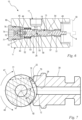
- the link 18 has a width b which corresponds to the distance between the side surfaces 77, 78 from one another, measured in the direction of the longitudinal central axis 14.
- the width b of the link 18 is constant. Due to the varying depth t of the link base 79, the size of the minimum flow cross section 19 is adjusted depending on a pivot angle ⁇ of the valve body 13 and the associated positioning of the valve seat 12 relative to the link 18. In an alternative embodiment of the pressure adjustment device 10, it may also be expedient to vary the width b of the link 18 in order to set the minimum flow cross section 19.
- Fig. 7 the arrangement of the valve body 13 and the valve seat 12 in the open state 32 and in the closed position 31 is shown in a schematic sectional view in the direction of the longitudinal central axis 14.
- the valve body 13 is shown in dashed lines in the closed position 31.
- the link 18 lies outside the end of the flow channel 38 facing the valve member 15.
- the flow channel 38 is closed by the peripheral section 20 of the valve member 15.
- the flow connection 70 between the inlet 16 and the outlet 17 of the pressure adjustment device 10 is interrupted.
- the valve body 13 is to be pivoted from the closed position 31 in a first pivoting direction 47 about the longitudinal central axis 14 of the valve body 13 into the open state 32.
- the flow channel 38 opens into the link 18 and the flow connection 70 is released.
- the pivot angle ⁇ of the valve body 13 is limited by mechanical stops, not shown.
- the maximum pivot angle ⁇ is the angle by which the valve body 13 pivots from the closed position 31 into the open state 32, in which the minimum flow cross section 19 is maximum.
- the maximum pivot angle ⁇ is in a range from 0° to 360°, preferably from 0° to 270°, in particular from 0° to 180°, particularly preferably from 0° to 90°.
- the maximum pivot angle ⁇ is particularly preferably at most 90°.
- the maximum pivot angle ⁇ is particularly preferably at least 30°, preferably at least 60°.
- the backdrop 18 is formed from three successive sections 81, 82, 83, namely the first section 81, the second section 82 and the third section 83.
- the sections 81, 82, 83 each consist of an approximately flat surface that forms the backdrop base 79.
- the valve body 13 is made of a metal material.
- the backdrop 18 is milled.
- the second section 82 is milled, with the second section 82 lying between the first section 81 and the third section 83.
- the first section 81 and the second section 83 are then milled one after the other.
- the link 18 can also be milled.
- the link 18 is preferably already produced in the casting process, in particular in an injection molding process of the valve body 13. If the valve body 13 is cast, the flow unit 30 can also be designed in the form of one or more openings in the peripheral section 20 instead of the link 18.
- the sections 81, 82, 83 are formed by chords 37, 37 ', 37" relative to a cross-sectional area 36 of the valve body 13, as shown in FIGS Figures 8 to 13 shown.
- the valve member 15 is cut by a transverse plane 35 aligned perpendicular to the longitudinal central axis 14.
- the transverse plane 35 intersects the valve member 15 on the link 18 in a cross-sectional area 36.
- the cross-sectional area 36 is limited in the area of the link 18 by the chords 37, 37 ', 37" forming the link 18. Outside the chords 37, 37', 37 ", the cross-sectional area 36 is limited by a circular arc 84 of the peripheral section 20.
- chords 37, 37', 37" each have a distance c" from the longitudinal central axis 14.
- the distance c of the first chord 37 of the first section 81 of the link 18 to the longitudinal central axis 14 is greater than the distance c 'of the second chord 37' of the second section 82 of the link 18 to the longitudinal central axis 14.
- the distance c' of the second chord 37 'of second section 82 of the link 18 to the longitudinal central axis 14 is greater than the distance c" of the third chord 37" of the third section 83 of the link 18 to the longitudinal central axis 14.
- the link 18 of the valve member 15 extends from a first end 21 to a second end 22 over an angular distance ⁇ measured with respect to the longitudinal central axis 14.
- the angular distance ⁇ in the exemplary embodiment is preferably at least 30°.
- the angular distance ⁇ is preferably at least 60°, in particular at least 90°, preferably approximately 120°.
- the angular distance ⁇ between the first end 21 and the second end 22 of the link 18 is advantageously at most 270°, preferably at most 180°, in particular at most 150°.
- the pressure adjustment device 10 is shown in an open state 32, with the minimum flow cross section 19 being maximum.
- the valve member 15 is aligned with respect to the valve seat 12 in such a way that a first valve opening 85 and a second valve opening 86 between the link 18 and the valve seat 12 are formed on the link. Accordingly, the flow connection 70 takes place starting from the flow channel 38 in the direction of the first end 21 of the link 18 via the second valve opening 86 and in the direction of the second end 22 of the link 18 via the first valve opening 85.
- the minimum flow cross section 19 results from the distance between the link base 79 of the link 18 and the valve seat 12.
- the minimum flow cross section 19 results from a first minimum flow cross section 19 'in the flow direction towards the first valve opening 85 and from a second minimum flow cross section 19" in the flow direction towards the second valve opening 86.
- first minimum flow cross section 19 ' directly at the second valve opening 86 between the Valve seat 12 and the first tendon 37 of the link 18 are formed.
- the second minimum flow cross section 19" is formed between the valve seat 12 at the end of the flow channel 38 and the third chord 37" of the link 18.
- the flow connection 70 takes place via a flow space 87, which is delimited by the flow section 56 of the valve body 13 and the valve housing 11.
- Open state 32 shown is preferably used in an exemplary embodiment of the pressure adjustment device 10, in which the actuation unit 50 is designed as a motor.
- the open state 32 forms a reference position of the valve body 13 relative to the valve seat 12, with a stop preferably being provided on the valve body 13, which contacts the valve seat 11 or the housing 12 in this position.
- a control (not shown) thus detects the position of the valve body 13.
- the pressure adjustment device 10 is shown in an open state 32.
- the valve body 13 is aligned such that the second valve opening 86 is closed. Accordingly, the valve body 13 is positioned relative to the valve seat 12 in such a way that the first end 21 of the link 18 rests on the valve seat 12.
- the valve body 13 is aligned such that only the first valve opening 85 is open.
- the minimum flow cross section 19 is formed by the distance between the second chord 37 'of the second section 82 of the link 18 and the valve seat 12 at the end of the flow channel 38. In the preferred embodiment, this position between the valve member 15 and the valve seat 12 forms the starting position 33 of the pressure adjusting device 10.
- the valve body 13 is only pivoted between the starting position 33 and the closed position 31. Since at most the first valve opening 85 is open in this angular range, the minimum flow cross section 19 and thus also the pressure at the inlet 16 can be controlled more easily.
- the link 18 is designed such that the minimum flow cross section 19 is reduced when pivoting in the first pivoting direction 48 starting from the starting position 33 of the valve body 13.
- the link 18 is designed such that the size of the minimum flow cross section 19 decreases at least partially linearly as the valve body 13 pivots in the first pivoting direction 48.
- the linear increase in the minimum flow cross section 19 preferably occurs when the valve body 13 is pivoted from the starting position 33 to an intermediate position 80.
- the intermediate position 80 is present when the minimum flow cross section 19 is formed by the distance between a connecting edge 88 and the valve seat 12.
- the connecting edge 88 is formed between the first chord 37 of the first section 81 and the second chord 37 'of the second section 82.
- a further linear increase in the minimum flow cross section 19 preferably occurs when the valve body 13 is pivoted from the intermediate position 80 into the closed position 31.
- the pressure adjustment device 10 is shown in the closed position.
- the opening of the flow channel 38 facing the valve member 15 is completely closed by the peripheral section 20 of the valve member 15.
- the link 18 is arranged outside the opening of the flow channel 38 facing the valve member 15.
- the flow connection 70 between inlet 16 and outlet 17 is prevented. Accordingly, there is no leakage current.
- the pressure at inlet 16 is maximum.
- the link 18 is designed such that the minimum flow cross section 19 continuously decreases when pivoting from the starting position 33 into the closed position 31. Accordingly, the pressure at the inlet 16 increases continuously when pivoting from the starting position 33 into the closed position 31.
- Fig. 14 a diagram is shown which shows the pressure at the inlet 16 as a function of the pivot angle ⁇ starting from the reference position 34.
- the pressure increases continuously from the starting position 33 to the closed position 31.
- a slight plateau is formed due to the connecting edge 88 between the first section 81 and the second section 82. If the pressure is adjusted gradually, it is advisable to provide an intermediate stage in the area of the intermediate position 80. In the area of the plateau, the slope of the pressure curve is extremely small, which means that the pressure change around the intermediate position is also extremely small. As a result, the target pressure desired for the intermediate position 80 can be reliably achieved even if the angular position of the actuating unit 50 is inaccurate.
- the pressure at the inlet 16 is preferably in a range between 30 and 50 bar.
- the pressure at the inlet 16 is preferably in a range between 40 and 60 bar.
- the pressure at the inlet 16 is preferably in a range between 70 and 90 bar.
- the pressure at the inlet 16 is preferably in a range between 120 and 150 bar.
Landscapes
- Engineering & Computer Science (AREA)
- General Engineering & Computer Science (AREA)
- Mechanical Engineering (AREA)
- Lift Valve (AREA)
Abstract
Description
- Die Erfindung betrifft eine Druckverstelleinrichtung für einen Hochdruckreiniger gemäß dem Oberbegriff des Anspruchs 1.
- Hochdruckreiniger dienen dazu, eine Reinigungsflüssigkeit, insbesondere Wasser, unter Druck zu setzen, und diese anschließend über einen Spritzaufsatz, beispielsweise eine Lanze mit Düsenkopf, auszustoßen und Gegenstände mit dem Flüssigkeitsstrahl zu reinigen. Zur Erzeugung des Druckes umfasst der Hochdruckreiniger eine Pumpe, die an ihrem Einlass mit einer Ansaugleitung, auch Niederdruckleitung genannt, und an ihrem Auslass mit einer Druckleitung, auch Hochdruckleitung genannt, verbunden ist. Über die Ansaugleitung wird der Pumpe Flüssigkeit zugeführt. Die Flüssigkeit wird durch die Pumpe unter Druck gesetzt und aus dem Auslass der Pumpe in die Druckleitung überführt. Ist der Spritzaufsatz geöffnet, strömt die Flüssigkeit unter hohem Druck aus dem Spritzaufsatz aus.
- Es sind Hochdruckreiniger bekannt, die eine Verstellung des Druckes an der Druckleitung vorsehen, um den Volumenstrom an dem Spritzaufsatz regulieren zu können. Eine Möglichkeit zur Regulierung des Volumenstroms ist einen Bypass zwischen der Druckleitung und der Ansaugleitung vorzusehen. In dem Bypass ist ein einstellbarer, minimaler Durchflussquerschnitt vorgesehen. Ist der minimale Durchflussquerschnitt erhöht, stellt sich an der Druckleitung ein erhöhter Verluststrom zur Ansaugleitung ein, wodurch der Druck in der Druckleitung und damit auch der Volumenstrom bei offenem Spritzaufsatz reduziert ist. Wird der Bypass geschlossen, entsteht kein Verluststrom. In der Druckleitung liegt der maximale Druck an, wodurch ein maximaler Volumenstrom bei offenem Spritzaufsatz ermöglicht ist.
- Im Bypass ist zur Einstellung des minimalen Durchflussquerschnittes ein Ventil vorgesehen, welches einen Ventilsitz und einen mit dem Ventilsitz zusammenwirkenden Ventilkörper umfasst. Ist das Ventil in geschlossenem Zustand, sitzt der Ventilkörper auf dem Ventilsitz, wodurch der Bypass zwischen der Druckleitung und der Ansaugleitung geschlossen ist. Zum Öffnen des Ventils ist der Ventilkörper vom Ventilsitz zu heben, wodurch das Ventil einen minimalen Durchflussquerschnitt freigibt. Das Abheben des Ventilkörpers vom Ventilsitz erfolgt durch eine translatorische Bewegung. Das Ventil ist dabei derart ausgebildet, dass sich mit zunehmendem Abstand zwischen Ventilkörper und Ventilsitz der minimale Durchflussquerschnitt vergrößert, wodurch der Druck in der Druckleitung abfällt. Derartige Systeme sind äußert komplex und unterliegen einer hohen Fertigungsgenauigkeit. Dadurch sind entsprechende Systeme recht kostenintensiv. Auch die Einstellung eines gezielten Druckes in der Druckleitung hat sich als äußerst schwierig erwiesen.
- Der Erfindung liegt die Aufgabe zugrunde, eine Druckverstelleinrichtung für einen Hochdruckreiniger anzugeben, die einen einfachen Aufbau aufweist und zugleich eine robuste Einstellung des Druckes in einer Druckleitung des Hochdruckreinigers ermöglicht.
- Die Erfindung wird durch eine Druckverstelleinrichtung für einen Hochdruckreiniger mit den Merkmalen des Anspruchs 1 gelöst.
- Die Druckverstelleinrichtung für einen Hochdruckreiniger umfasst ein Ventilgehäuse mit einem Ventilsitz, mindestens einen Einlass zum Zuführen einer Flüssigkeit, mindestens einen Auslass zum Abführen der Flüssigkeit und einen Ventilkörper mit einer Längsmittelachse, wobei der Ventilkörper in dem Ventilgehäuse um seine Längsmittelachse schwenkbar gelagert ist, wobei der Ventilkörper bezogen auf seine Längsmittelachse umfangsseitig ein dem Ventilsitz zugeordnetes Ventilglied aufweist, wobei in einer Schließstellung des Ventilkörpers der Ventilsitz durch das Ventilglied verschlossen ist und die Strömungsverbindung zwischen dem Einlass und dem Auslass unterbrochen ist, wobei der Ventilköper um seine Längsmittelachse von der Schließstellung in einen Offenzustand schwenkbar ist, wobei in dem Offenzustand eine Strömungsverbindung zwischen dem Einlass und dem Auslass mit einem minimalen Durchflussquerschnitt vorgesehen ist, wobei der minimale Durchflussquerschnitt durch eine an dem Ventilglied ausgebildete Strömungseinheit gebildet ist und das Ventilglied derart ausgebildet ist, dass die Größe des minimalen Durchflussquerschnitts in Abhängigkeit eines Schwenkwinkels des Ventilkörpers um seine Längsmittelachse einstellbar ist.
- Das Öffnen und Schließen des Ventils der Druckverstelleinrichtung erfolgt durch das Schwenken des Ventilgliedes. Die Strömungseinheit an dem Ventilglied ist derart ausgebildet, dass die Größe des minimalen Durchflussquerschnittes in Abhängigkeit des Schwenkwinkels des Ventilkörpers einstellbar ist. Bei den herkömmlichen, translatorisch bewegbaren Ventilkörpern führt bereits eine geringe Bewegung des Ventilkörpers zu einer großen Änderung des minimalen Durchflussquerschnittes. Somit ist das Druckeinstellverhalten äußerst sensitiv und empfindlich gegenüber Fertigungstoleranzen. Die Strömungseinheit am Ventilglied, welches am Umfang des Ventilkörpers angeordnet ist, ermöglicht eine Einstellung des minimalen Durchflussquerschnittes in Abhängigkeit des Schwenkwinkels des Ventilkörpers. Das Druckeinstellverhalten ist weniger sensitiv und unempfindlich gegenüber Fertigungstoleranzen des Ventilkörpers. Ferner ist das rotatorische Bewegungsprinzip des Ventilkörpers mechanisch einfacher zu realisieren als die translatorische Verschiebung eines Ventilkörpers.
- Es ist vorteilhaft vorgesehen, dass der Schwenkwinkel in einem Bereich von 0° bis 360°, insbesondere von 0° bis 270°, vorzugsweise von 0° bis 180°, bevorzugt von 0° bis 90° liegt. Ist der Schwenkwinkel zu groß gewählt, kann dies zu einer zu langen Einstelldauer des Druckes führen. Daher ist der Schwenkwinkel zur Einstellung des minimalen Durchflussquerschnittes ausreichend gering gewählt, so dass die Einstellung des Druckes über das gesamte Druckspektrum auf schnelle Weise erfolgen kann. Der gewählte Schwenkwinkel erlaubt eine einfache und schnelle Einstellung des Ventilkörpers von Hand, da der für den Bediener zu schwenkende Winkel bereits mit einer einzigen Handbewegung erfolgen kann. So kann vorteilhaft vorgesehen sein, dass die Druckverstelleinrichtung eine auf das erste Ende des Ventilkörpers wirkende Betätigungseinheit zum Schwenken des Ventilkörpers umfasst. Besonders vorteilhaft umfasst die Betätigungseinheit eine Rastung zum stufenweisen Schwenken des Ventilkörpers. Die Rastung weist mehrere Stufen, vorzugsweise drei Stufen auf. Es kann auch zweckmäßig sein, mehr als 3 Stufen vorzusehen. Die Betätigungseinheit weist eine erste Schwenkrichtung und eine der ersten Schwenkrichtung entgegengesetzte zweite Schwenkrichtung auf. Der minimale Durchflussquerschnitt der Strömungseinheit erhöht sich beim Schwenken des Ventilkörpers ausgehend von der Schließstellung in die erste Schwenkrichtung. Wird der Ventilkörper in die zweite Schwenkrichtung zurückgeschwenkt, verringert sich der minimale Durchflussquerschnitt in der Strömungseinheit. Zudem erlaubt der geringe Schwenkwinkel auch eine schnelle Einstellung über einen Elektromotor. Bevorzugt umfasst die Betätigungseinheit einen Stellmotor (Servomotor) oder einen Schrittmotor zum Schwenken des Ventilkörpers. Es können auch andere Motoren zweckmäßig sein. Dadurch wird ein automatisches Einstellen des minimalen Durchflussquerschnittes ermöglicht.
- Es ist vorteilhaft vorgesehen, dass die Strömungseinheit als Kulisse an einem Umfangsabschnitt des Ventilgliedes ausgebildet ist. Demnach wird über die Kulisse eine Strömungsverbindung zwischen dem Einlass der Druckverstelleinrichtung und dem Auslass der Druckverstelleinrichtung hergestellt. Zur Einstellung des minimalen Durchflussquerschnittes ist der Ventilkörper mit der Kulisse entsprechend zum Ventilsitz zu positionieren. Die Kulisse ist vorzugsweise derart ausgebildet, dass der Druck am Einlass kontinuierlich verstellbar ist. Wird das Ventilglied mit der Kulisse ausgehend von der Schließstellung in die erste Schwenkrichtung geschwenkt, nimmt der minimale Durchflussquerschnitt zu, wodurch sich der Druck am Einlass reduziert. Wird das Ventilglied mit der Kulisse in die zweite Schwenkrichtung zur Schließstellung hin geschwenkt, reduziert sich der minimale Durchflussquerschnitt, wodurch sich der Druck am Einlass erhöht.
- Mit zunehmender Länge der Kulisse, also dem Winkelabstand der beiden Enden der Kulisse zueinander, erhöht sich die Einstellauflösung des minimalen Durchflussquerschnittes. Ferner nimmt die Sensitivität der Druckeinstellvorrichtung bei der Einstellung des minimalen Durchflussquerschnitts und des damit verbundenen Druckes am Einlass der Druckeinstelleinrichtung ab. Somit ist die Druckverstelleinrichtung weniger empfindlich gegenüber hohen Fertigungstoleranzen oder ungenauer Einstellung des Schwenkwinkels. Mit abnehmender Länge der Kulisse ist eine mechanisch schnellere Verstellung des minimalen Durchflussquerschnittes und des damit verbundenen Druckes am Einlass möglich. Aus diesen Erkenntnissen haben sich die folgenden Werte für die Kulisse ergeben. Die Kulisse des Ventilgliedes erstreckt sich von ihrem ersten Ende bis zu ihrem zweiten Ende über einen bezüglich der Längsmittelachse gemessenen Winkelabstand, wobei der Winkelabstand mindestens 30° beträgt. Bevorzugt beträgt der Winkelabstand mindestens 60°, insbesondere mindestens 90°, vorzugsweise in etwa 120°. Vorteilhaft beträgt der Winkelabstand zwischen dem ersten Ende und dem zweiten Ende der Kulisse höchstens 270°, vorzugsweise höchstens 180°, insbesondere höchstens 150°.
- Über den Mindestwinkelabstand der Enden der Kulisse ist gewährleistet, dass der minimale Durchflussquerschnitt und damit auch der am Einlass anliegende Druck eine hohe Einstellauflösung aufweist. Der Höchstwinkelabstand der Enden der Kulisse ist derart gewählt, dass der resultierende Verstellweg ausreichend kurz gehalten ist, um ein schnelles Verstellen des minimalen Durchflussquerschnittes zu ermöglichen.
- Es ist vorteilhaft vorgesehen, dass die Kulisse derart ausgebildet ist, dass die Größe des minimalen Durchflussquerschnitts zumindest teilweise linear in Abhängigkeit des Schwenkwinkels des Ventilkörpers um seine Längsmittelachse einstellbar ist. Dadurch gestaltet sich die Einstellung des Druckes für den Bediener sehr intuitiv.
- Es ist bevorzugt vorgesehen, dass das Ventilglied eine senkrecht zur Längsmittelachse ausgerichtete Querebene aufweist, wobei die Querebene den Ventilkörper mit der Kulisse in einer Querschnittsfläche schneidet, wobei die Querschnittsfläche an der Kulisse durch mehrere Sehnen begrenzt ist. Die Sehnen entsprechen dem Grund der Kulisse. Durch diese Ausgestaltung der Kulisse kann das Ventilglied mit der Kulisse auf einfache Weise gefertigt, insbesondere gefräst werden.
- Vorzugsweise weist der Ventilsitz einen Strömungskanal auf, wobei der Strömungskanal gegenüber dem Ventilglied derart angeordnet ist, dass der Strömungskanal im Offenzustand des Ventilgliedes in eine Abströmöffnung der Strömungsverbindung mündet. Der Strömungskanal kann bevorzugt als eine Düse ausgebildet sein.
- Es ist insbesondere vorgesehen, dass an dem Ventilkörper stromabwärts des Ventilsitzes ein Rückschlagelement vorgesehen ist, wobei das Rückschlagelement als ein am Ventilkörper angeordneter O-Ring ausgebildet ist. Vorzugsweise weist der Ventilkörper ein erstes freies Längsende und ein zweites Längsende auf, wobei der Ventilkörper an seinem zweiten Längsende in Richtung der Längsmittelachse über ein Axiallager am Ventilgehäuse gelagert ist. Bevorzugt umfasst das Axiallager eine am zweiten Ende des Ventilkörpers ausgebildete Aufnahme und mindestens eine in der Aufnahme gehaltene Kugel, wobei der Ventilkörper über die Kugel gegenüber dem Ventilgehäuse abgestützt ist. Die in der Aufnahme gehaltene Kugel stellt eine einfache Konstruktion eines Axiallagers da und dient zur Minimierung der Reibung beim Schwenken des Ventilkörpers. Es kann auch zweckmäßig sein, mehrere Kugeln zur Abstützung des Ventilkörpers vorzusehen.
- Weitere Merkmale der Erfindung ergeben sich aus der Beschreibung und der Zeichnung, in der ein nachfolgend im Einzelnen beschriebenes Ausführungsbeispiel der Erfindung dargestellt ist. Es zeigen:
- Fig. 1
- in perspektivischer, schematischer Darstellung einen Hochdruckreiniger,
- Fig. 2
- in einer schematischen Darstellung eine Druckverstelleinrichtung angebunden an einer Druckleitung und einer Ansaugleitung eines Hochdruckreinigers,
- Fig. 3
- in einer perspektivischen Darstellung einen Ventilkörper und einen Ventilsitz der Druckverstelleinrichtung nach
Fig. 2 - Fig. 4
- in einer perspektivischen, ausschnittsweisen Darstellung den Ventilkörper mit Kulisse
- Fig. 5
- in einer Schnittdarstellung die Druckverstelleinrichtung mit Ventilsitz,
- Fig. 6
- in einer Schnittdarstellung entlang der Schnittlinie zwischen den Pfeilen VI nach
Fig. 5 die Druckverstelleinrichtung, - Fig. 7
- in einer Schnittdarstellung der Ventilkörper mit Ventilsitz in Schließstellung und Referenzstellung,
- Fig. 8
- in einer Schnittdarstellung die Druckverstelleinrichtung in Referenzstellung,
- Fig. 9
- in einer ausschnittsweisen Schnittdarstellung die Anordnung des Ventilgliedes und des Ventilsitzes in Referenzstellung,
- Fig. 10
- in einer Schnittdarstellung die Druckverstelleinrichtung in Startstellung,
- Fig. 11
- in einer ausschnittsweisen Schnittdarstellung die Anordnung des Ventilgliedes und des Ventilsitzes in Startstellung,
- Fig. 12
- in einer Schnittdarstellung die Druckverstelleinrichtung in Schließstellung,
- Fig. 13
- in einer ausschnittsweisen Schnittdarstellung die Anordnung des Ventilgliedes und des Ventilsitzes in Schließstellung und
- Fig. 14
- ein schematisches Diagramm des Druckverlaufes in Abhängigkeit des Schwenkwinkels.
-
Fig. 1 zeigt eine schematische Darstellung einer Ausführung des erfindungsgemäßen Hochdruckreinigers 1. Der Hochdruckreiniger 1 umfasst ein Gehäuse 2, das einzelne Systemkomponenten einer Hydraulikeinheit umgibt und diese beispielsweise vor Spritzwasser schützt. An dem Gehäuse 2 ist ein Niederdruckanschluss 4 vorgesehen, über welchen eine Ansaugleitung 5 (Fig. 2 ) des Hochdruckreinigers 1 mit einem externen Flüssigkeitsanschluss, insbesondere mit einem Wasseranschluss, verbindbar ist. Demnach wird dem Hochdruckreiniger 1 in dessen Betrieb über den Niederdruckanschluss 4 eine Reinigungsflüssigkeit zugeführt. Die Reinigungsflüssigkeit ist vorzugsweise Wasser. Es können auch andere Flüssigkeiten, beispielsweise Wasser versetzt mit einem Reinigungsmittel, als Reinigungsflüssigkeit vorgesehen sein. Auf dem Gehäuse 2 des Hochdruckreinigers 1 ist eine Schlauchtrommel 7 vorgesehen. Auf der Schlauchtrommel 7 ist ein Hochdruckschlauch 8 aufgewickelt. Der Hochdruckschlauch 8 ist an seinem einen Ende mit einer Druckleitung 6 des Hochdruckreinigers 1 verbunden (Fig. 2 ). An dem anderen Ende des Hochdruckschlauchs 8 ist ein Druckanschluss 9 vorgesehen, an dem ein Spritzaufsatz 3 (Figur 2 ), beispielsweise eine Spritzpistole mit einem Düsenkopf, anschließbar ist. - Wie in
Fig. 1 gezeigt, umfasst der Hochdruckreiniger 1 einen Betätigungsschalter 60, mittels dessen der Hochdruckreiniger 1 an- und ausgeschaltet werden kann. Zudem ist auf der Oberseite des Gehäuses 2 ein Haltegriff 61 vorgesehen. Der Hochdruckreiniger 1 kann an seinem Haltegriff 61 angehoben, insbesondere getragen oder über seine an der Unterseite des Gehäuses 2 angeordneten Räder 62 gezogen werden. - Wie in
Fig. 2 gezeigt, umfasst der Hochdruckreiniger 1 eine Pumpe 63, die durch einen Antriebsmotor 64 angetrieben ist. Der Antriebsmotor 64 ist im Ausführungsbeispiel als Elektromotor ausgebildet. In einer alternativen Ausführung des Hochdruckreinigers 1 sind auch andere Arten des Antriebsmotors 64 denkbar. Über die Ansaugleitung 5 wird der Pumpe 63 Flüssigkeit zugeführt. Vom Antriebsmotor angetrieben fördert die Pumpe 63 die Flüssigkeit unter Hochdruck in die Druckleitung 6. An der Pumpe 63 sind Rückschlagventile 65 vorgesehen, um einen Druckausgleich der Flüssigkeit zwischen der Druckleitung 6 und der Ansaugleitung 5 über die Pumpe 63 zu vermeiden. Ist der Spritzaufsatz 3 verschlossen, steigt der Druck in der Druckleitung 6 an. Nach Erreichen eines Grenzdruckes in der Druckleitung 6 wird der Antriebsmotor 64 abgeschaltet. Hierfür kann beispielsweise ein Druckabschaltventil vorgesehen sein. Ist der Spritzaufsatz 6 geöffnet, strömt die Flüssigkeit von der Pumpe 63 über die Druckleitung 6 zum Düsenkopf des Spritzaufsatzes 3 und strömt dort mit hoher Geschwindigkeit aus. - Wie in
Fig. 2 gezeigt, umfasst der Hochdruckreiniger 1 eine Druckverstelleinrichtung 10. Die Druckverstelleinrichtung 10 ist funktional zwischen der Druckleitung 6 und der Ansaugleitung 5 angeordnet. Die Druckverstelleinrichtung 10 ist derart ausgebildet, dass diese in einem Offenzustand (Fig. 3 ) eine Strömungsverbindung 70 zwischen der Druckleitung 6 und der Ansaugleitung 5 freigibt. Folglich fließt die Reinigungsflüssigkeit unter hohem Druck von der Druckleitung 6 über die Druckverstelleinrichtung 10 zur Ansaugleitung 5. Es entsteht ein Verluststrom zwischen der Druckleitung 6 und der Ansaugleitung 5, der einen Druckabfall in der Druckleitung 6 bewirkt. Mit Abnahme des Druckes in der Druckleitung 6 reduziert sich auch der Volumenstrom am Düsenkopf des Spritzaufsatzes 3 und damit die Geschwindigkeit, mit der die Flüssigkeit aus dem Spritzaufsatz 3 ausströmt. Die Druckverstelleinrichtung 10 ist derart ausgebildet, dass der Verluststrom zwischen der Druckleitung 6 und der Ansaugleitung 5 und damit auch der Druck in der Druckleitung 6 einstellbar ist. Ist die Druckverstelleinrichtung 10 in einer Schließstellung 31, ist die Strömungsverbindung 70 zwischen der Druckleitung 6 und der Ansaugleitung 5 über die Druckverstelleinrichtung 10 unterbunden. In der Schließstellung 31 der Druckverstelleinrichtung 10 liegt kein Verluststrom vor. Der Druck in der Druckleitung 6 ist in Betrieb des Hochdruckreinigers 1 in der Schließstellung 31 der Druckverstelleinrichtung maximal. Folglich ist auch der Volumenstrom am Düsenkopf des Spritzaufsatzes 3 maximal. - Wie in
Fig. 2 gezeigt, umfasst die Druckverstelleinrichtung 10 ein Ventilgehäuse 11 und einen Ventilkörper 13 mit einem Ventilglied 15. Der Ventilkörper 13 ist im Ventilgehäuse 11 um seine Längsmittelachse 14 schwenkbar gelagert. Die Druckverstelleinrichtung 10 umfasst einen Ventilsitz 12, wobei der Ventilsitz 12 mit dem Ventilglied 15 des Ventilkörpers 13 in Wirkverbindung steht. Zudem umfasst die Druckverstelleinrichtung 10 einen Einlass 16 zum Zuführen der Flüssigkeit. Die Druckverstelleinrichtung 10 umfasst einen Auslass 17 zum Abführen der Flüssigkeit. Wie inFig. 2 gezeigt, ist der Einlass 16 der Druckverstelleinrichtung 10 mit der Druckleitung 6 des Hochdruckreinigers 1 strömungsverbunden. Der Auslass 17 der Druckverstelleinrichtung 10 ist mit der Ansaugleitung 5 des Hochdruckreinigers 1 strömungsverbunden. In einer alternativen Ausführung der Druckverstelleinrichtung 10 können auch mehrere Einlässe 16 und / oder mehrere Auslässe 17 vorgesehen sein. - Wie in
Fig. 3 gezeigt, ist der Ventilkörper 13 als eine Spindel ausgebildet. Der Ventilkörper 13 erstreckt sich entlang seiner Längsmittelachse 14 von seinem ersten Längsende 41 bis zu seinem zweiten Längsende 42. An dem ersten Längsende 31 ist ein Betätigungsabschnitt 49 ausgebildet. Der Betätigungsabschnitt 49 ist mit einer Betätigungseinheit 50 (Fig. 6 ) wirkverbunden. Über die Betätigungseinheit 50 kann der Ventilkörper 13 um seine Längsmittelachse 14 geschwenkt werden. Die Betätigungseinheit 50 ist im Ausführungsbeispiel mit den Ventilkörper 13 formschlüssig verbunden. Hierzu ist der Betätigungsabschnitt 49 als ein Flachkant ausgebildet. In einer alternativen Ausführung der Druckverstelleinrichtung 10 kann es zweckmäßig sein, auch andere Verbindungsarten, beispielsweise einen Reibkraftschluss, zwischen der Betätigungseinheit 50 und dem Ventilkörper 13 vorzusehen. - Wie in
Fig. 3 gezeigt, umfasst der Ventilkörper 13 mindestens einen umfangsseitig ausgebildeten ersten Lagerabschnitt 28. Das bevorzugte Ausführungsbeispiel der Druckverstelleinrichtung 10 umfasst neben dem ersten Lagerabschnitt 28 einen zweiten Lagerabschnitt 29. Beide Lagerabschnitte 28, 29 sind an der Umfangsfläche des Ventilkörpers 13 ausgebildet. Der erste Lagerabschnitt 28 schließt unmittelbar an dem Befestigungsabschnitt 49 an. Der zweite Lagerabschnitt 29 ist am zweiten Längsende 42 des Ventilkörpers 13 ausgebildet. Wie insbesondere in denFiguren 5 und6 gezeigt, ist der Ventilkörper 13 über eine Lagerung an dem Ventilgehäuse 11 schwenkbar gelagert. Die Lagerung umfasst im Ausführungsbeispiel zwei Radiallager 51, 52. Das erste Lager 51 ist an dem ersten Lagerabschnitt 28, das zweite Lager 52 an dem zweiten Lagerabschnitt 29 des Ventilkörpers 13 angeordnet. Die Anzahl der Lagerabschnitte 28, 29 des Ventilkörpers 13 korrespondiert mit der Anzahl der Radiallager 28, 29. Die Lager 51, 52 sind im bevorzugten Ausführungsbeispiel als Nadellager ausgebildet. Selbstverständlich können die Lager in einer alternativen Ausführung auch als Gleitlager, insbesondere als Graphitlager oder ähnliche ausgebildet sein. Es kann auch zweckmäßig sein, lediglich ein Radiallager oder mehr als zwei Radiallager vorzusehen. - Wie in
Fig. 3 gezeigt, umfasst der Ventilkörper 13 an seiner Umfangsseite das Ventilglied 15 mit einer Strömungseinheit 30. Der Ventilsitz 12 ist dem Ventilglied 15 zugeordnet. Der Ventilsitz 12 ist aus einem im Ventilgehäuse 11 angeordneten Kanaleinsatz 39 gebildet. Dadurch ist die Herstellung des Ventilsitzes 12 vereinfacht. Es kann auch zweckmäßig sein, den Ventilsitz 12 unmittelbar am Ventilgehäuse 11 auszubilden. Der Kanaleinsatz 39 umfasst einen Strömungskanal 38. Das eine Ende des Strömungskanals 38 grenzt unmittelbar am Einlass 16 der Druckverstelleinrichtung 10 an. Das andere Ende des Strömungskanals 38 grenzt an dem Ventilglied 15 an. - Befindet sich die Druckverstelleinrichtung 10 in der Schließstellung 31, ist der Ventilsitz 12 durch das Ventilglied 15 verschossen. Demnach liegt das Ventilglied 15 derart an dem Ventilsitz 12, insbesondere an dem Kanaleinsatz 39, an, dass der Strömungskanal 38 an seinem dem Ventilglied 15 zugewandten Ende verschlossen ist. Die Strömungsverbindung 70 zwischen dem Einlass 16 und dem Auslass 17 ist unterbrochen. Befindet sich die Druckverstelleinrichtung 10 in dem Offenzustand 32, ist die Strömungsverbindung 70 zwischen dem Einlass 16 und dem Auslass 17 freigegeben. Der Ventilkörper 13 ist in dem Offenzustand 32 der Druckverstelleinrichtung 10 derart geschwenkt, dass die Strömungseinheit 30 des Ventilgliedes 15 an dem einen Ende des Strömungskanals 38 anliegt. Der Strömungskanal 38 mündet in dem Offenzustand 32 der Druckverstelleinrichtung 10 in eine Abströmöffnung 25 der Strömungseinheit 30, wodurch die Strömungsverbindung 70 zwischen Einlass 16 und dem Auslass 17 freigegeben ist.
- Wie in den
Figuren 3 ,5 ,6 gezeigt, umfasst der Ventilkörper 13 einen an der Umfangsseite des Ventilkörpers 13 ausgebildeten Strömungsabschnitt 56. Der Strömungsabschnitt 56 umgibt die Strömungseinheit 30. Der Strömungsabschnitt 56 des Ventilkörpers 13 ist beabstandet zum Ventilgehäuse 11 ausgebildet. Demnach im Bereich des Strömungsabschnittes 56 zwischen dem Ventilgehäuse 11 und dem Ventilkörper 13 Flüssigkeit strömen. Ferner umfasst der Ventilkörper 13 einen Innenkanal 53. Der Ventilkörper 13 weist eine erste Verbindungsöffnung 54 auf, über die der Innenkanal 53 mit dem Strömungsabschnitt 56 des Ventilkörpers 13 strömungsverbunden ist. Der Ventilkörper 13 weist eine zweite Verbindungsöffnung 55 auf, wobei sich die Verbindungsöffnung 55 von der Umfangsseite des Ventilkörpers 13 zum Innenkanal 53 erstreckt, wodurch dieser mit dem Auslass 17 strömungsverbunden ist. Die Verbindungsöffnungen 54, 55 sind bevorzugt als Bohrungen ausgebildet. - Wie in
Fig. 3 gezeigt, ist die Druckverstelleinrichtung 10 derart ausgebildet, dass in ihrem Offenzustand 32 die Strömungsverbindung 70 vom Einlass 16 bis hin zum Auslass 17 über den Strömungskanal 38, die Strömungseinheit 30, den Strömungsabschnitt 56, die erste Verbindungsöffnung 54, den Innenkanal 53 und die zweite Verbindungsöffnung 55 erfolgt. - Wie in
Fig. 5 gezeigt, ist der Strömungsabschnitt 56 durch zwei zwischen dem Ventilkörper 13 und dem Ventilgehäuse 11 angeordneten Dichtungen 57, 58 abgedichtet. Die erste Dichtung 57 und die zweite Dichtung 58 sitzen jeweils in einer am Ventilkörper 13 vorgesehen Nut. Die Dichtungen 57, 58 sind im bevorzugten Ausführungsbeispiel durch O-Ringe gebildet. Ferner umfasst die Druckverstelleinrichtung 10 eine dritte Dichtung 59. Die zweite Verbindungsöffnung 55 und damit auch der Auslass 17 sind durch die zweite Dichtung 58 und durch die dritte Dichtung 59 abgedichtet. Auch die dritte Dichtung 59 ist als ein O-Ring ausgebildet und in einer Nut des Ventilkörpers 13 angeordnet. Die gesamte Strömungsverbindung 70 ist gegenüber dem ersten Lager 51 durch die ersten Dichtung 57 abgedichtet. Die gesamte Strömungsverbindung 70 ist gegenüber dem zweiten Lager 52 durch die dritte Dichtung 59 abgedichtet. - Wie in
Fig. 5 gezeigt, umfasst die Druckverstelleinrichtung 10 ein Rückschlagelement 26, wobei das Rückschlagelement 26 funktional vor dem Auslass 17 angeordnet ist und eine Strömung in Richtung von dem Auslass 17 zum Einlass 16 hin unterbindet. Das Rückschlagelement 26 ist im bevorzugten Ausführungsbeispiel als ein Dichtring, insbesondere als ein O-Ring ausgebildet. Das Rückschlagelement 26 liegt in einer an der Umfangsseite des Ventilkörpers 13 ausgebildeten Nut 27. Die zweite Verbindungsöffnung 55 mündet in die Nut 27. Die Nut 27 ist im Ausführungsbeispiel keilförmig angeordnet, wobei die Seitenflächen der Nut 27 zur Längsmittelachse 14 hin zusammenlaufen. Die Anordnung aus Rückschlagelement 26 und der Nut 27 ist derart ausgebildet, dass in Schließstellung 31 der Druckverstelleinrichtung 10 das Rückschlagelement 26 dichtend an der Nut 27 anliegt und in dem Offenzustand 32 der Druckverstelleinrichtung 10 das Rückschlagelement 26 durch den Druck der Flüssigkeit radial nach außen gespreizt wird und die Strömungsverbindung 70 freigibt. Wirkt in der Schließstellung 31 Druck der Flüssigkeit vom Auslass 17 in Richtung zum Einlass 16, wird das Rückschlagelement 26 gegen die Nut 27 gepresst und dichtet dadurch die zweite Verbindungsöffnung 55 ab. Ein Rückströmen der Flüssigkeit vom Auslass 17 zum Einlass 16 hin ist unterbunden. - Wie in
Fig. 6 gezeigt, umfasst die Druckverstelleinrichtung 10 die Betätigungseinheit 50 zum Schwenken des Ventilkörpers 13 um die Längsmittelachse 14. Die Betätigungseinheit 50 ist im Ausführungsbeispiel der Druckverstelleinrichtung 10 über den Betätigungsabschnitt 49 des Ventilkörpers 13 mit dem Ventilkörper 13 drehfest verbunden. Die Betätigungseinheit 50 ist im Ausführungsbeispiel als ein Drehknopf ausgebildet. Durch den Drehknopf kann der Ventilkörper 13 von Hand geschwenkt werden. Im vorliegenden Ausführungsbeispiel ist der Drehknopf unmittelbar auf dem Betätigungsabschnitt 49 gehalten. Es kann auch vorgesehen sein, dass die Betätigungseinheit 50 ein Getriebe aufweist. In einer solchen Ausführung ist das Bedienelement, hier der Druccknopf mittelbar mit dem Betätigungsabschnitt 50 des Ventilkörpers 13 wirkverbunden. Die Betätigungseinheit 50 ist derart ausgebildet, dass ein stufenloses Schwenken des Ventilkörpers 13 vorgesehen ist. In einer alternativen Ausführung kann es zweckmäßig sein, dass die Betätigungseinheit 50 eine Rastung aufweist. Die Rastung sieht mehrere Schwenkstufen, insbesondere drei Schwenkstufen vor. Es kann auch zweckmäßig sein, mehr als drei Schwenkstufen, insbesondere 4 oder 5 Schwenkstufen vorzusehen. In einer weiteren alternativen Ausgestaltung der Druckverstelleinrichtung 10 kann es zweckmäßig sein, dass die Betätigungseinheit 50 als Druckknopf mit einem Spannwerk, insbesondere einem Sperrspannwerk, ausgebildet ist. In einer solchen Ausführung sieht die Betätigungseinheit 50 ebenfalls mehrere Schwenkstufen des Ventilkörpers 13 vor. In einer weiteren alternativen, nicht näher dargestellten Ausführung der Druckverstelleinrichtung 10 umfasst die Betätigungseinheit 50 einen Stellmotor oder einen Schrittmotor zum Schwenken des Ventilkörpers 13. Das Schwenken des Ventilkörpers 13 kann dann motorisch bzw. automatisch erfolgen. Der Schwenkwinkel wird dann vorzugsweise in Abhängigkeit des vom Bediener betätigten, an dem Spritzaufsatz vorgesehenen Bedienelementes bestimmt. - Wie in
Fig. 5 gezeigt, ist der Ventilkörper 13 in Richtung seiner Längsmittelachse 14, also in Axialrichtung des Ventilkörpers 13, gegenüber dem Ventilgehäuse 11 gelagert. Die Druckverstelleinrichtung 10 umfasst ein Axiallager 43. Das Axiallager 43 ist am zweiten Längsende 42 des Ventilkörpers 13 angeordnet. Das Axiallager 43 umfasst mindestens eine Aufnahme 44 und mindestens eine in der Aufnahme 44 gehaltene Kugel 45. Die Aufnahme 44 ist koaxial zur Längsmittelachse 14 ausgerichtet. Demnach schneidet die Längsmittelachse 14 des Ventilkörpers 13 die Kugel 45 in ihrem Mittelpunkt. Die Aufnahme 44 ist durch eine Sacklochbohrung 67 in einem Verschlusselement 66 gebildet. Das Verschlusselement 66 sitzt am zweiten Längsende 42 des Ventilkörpers 13. Der Innenkanal 53 ist als Sacklochbohrung ausgebildet. Das Verschlusselement 66 ragt in den Innenkanal 53, wobei zwischen dem Verschlusselement 66 und dem Ventilkörper 13 eine Dichtung zur Abdichtung des Innenkanals 53 zum zweiten Längsende 42 des Ventilkörpers 13 hin angeordnet ist. - Wie in
Fig. 5 gezeigt, ist im Ventilgehäuse 11 eine Montageöffnung 73 zum Einführen des Ventilkörpers 13 in das Ventilgehäuse 11 vorgesehen. Ist der Ventilkörper 13 in dem Ventilgehäuse 11 angeordnet, ist die Montageöffnung 73 zu schließen. Hierfür umfasst das Ventilgehäuse 11 eine Verschlusseinheit 71. Die Verschlusseinheit 71 umfasst eine Verschlussschraube 76 mit einem Gewinde 72, einen Einsatz 74 und eine im Einsatz 74 gehaltene Stützkugel 75. Die Verschlussschraube 76 ist mit dem Grundkörper 69 des Ventilgehäuses 11 verschraubt, wobei zwischen der Verschlussschraube 76 und dem Grundkörper 69 eine Dichtung, insbesondere ein Dichtring, angeordnet ist. Der in der Verschlussschraube 76 gehaltene Einsatz 74 ist koaxial zur Längsmittelachse 14 ausgerichtet. Auch die Stützkugel 75 ist derart in dem Einsatz 74 angeordnet, dass die Längsmittelachse 14 des Ventilkörpers 13 die Stützkugel 75 in ihrem Mittelpunkt schneidet. Die Kugel 45 und die Stützkugel 75 kontaktieren sich. Die Kugel 45 ist in ihrer Aufnahme 44 drehbar gelagert. Die Stützkugel 75 ist in ihrem Einsatz drehbar gelagert. Durch den Punktkontakt zwischen der Kugel 45 und der Stützkugel 75 sind die der Schwenkbewegung des Ventilkörpers 13 entgegenwirkenden Reibungskräfte minimiert. Im bevorzugten Ausführungsbeispiel sind Bestandteile der Axiallagerung 43 die Aufnahme 44, die Kugel 45, der Einsatz 74 und die Stützkugel 75. Der Kraftfluss der wirkenden Axialkräfte verläuft über den Ventilkörper 13, die Aufnahme 44, die Kugel 45, die Stützkugel 75, dem Einsatz 74, die Verschlussschraube 76 über das Gewinde 72 in den Grundkörper 69 des Ventilgehäuses 11. - Die Druckverstelleinrichtung 10 weist einen minimalen Durchflussquerschnitt 19 innerhalb der Strömungsverbindung 70 zwischen dem Einlass 16 und dem Auslass 17 auf. Der minimale Durchflussquerschnitt 19 ist der Bereich der Strömungsverbindung 70, in dem der minimale Strömungsquerschnitt vorliegt. Der minimale Durchflussquerschnitt 19 ist in der Strömungseinheit 30 vorgesehen. Die Strömungseinheit 30 ist derart ausgebildet, so dass der minimale Durchflussquerschnitt einstellbar ist. Demnach bilden das Ventilglied 15 mit der Strömungseinheit 30 und dem Ventilsitz 12 ein einstellbares Drosselventil. Somit kann der Volumenstrom der Strömungsverbindung 70 zwischen dem Einlass 16 und dem Auslass 17 durch die Strömungseinheit 30 angepasst werden, wodurch der Druck am Einlass 16 und damit in der Druckleitung 6 des Hochdruckreinigers 1 einstellbar ist.
- In den
Figuren 3 und4 ist die Strömungseinheit 30 des Ventilgliedes 15 gezeigt. Die Strömungseinheit 30 umfasst. Die Strömungseinheit 30 ist im Ausführungsbeispiel als eine Kulisse 18 ausgebildet. Die Kulisse 18 ist an einem Umfangsabschnitt 20 des Ventilkörpers 13 ausgebildet. Die Kulisse 18 ist als eine Nut ausgebildet. Die Kulisse 18 umfasst eine ersten Seitenfläche 77, eine zweite Seitenfläche 78 sowie einen die Seitenflächen 77, 78 verbindenden Kulissengrund 79. In der Schließstellung 31 der Druckverstelleinrichtung 10 ist das Ventilglied 15 derart gegenüber dem Ventilsitz 12 ausgerichtet, dass der Strömungskanal 38 an seinem dem Ventilglied 15 zugewandten Ende vollumfänglich auf dem Umfangsabschnitt 20 außerhalb der Kulisse 18 anliegt. Der Strömungskanal 38 ist durch den Umfangsabschnitt 20 des Ventilkörpers 13 verschlossen. Um den Strömungskanal 38 freizugeben, ist der Ventilkörper 13 mit dem Ventilglied 15 zu schwenken, bis der Strömungskanal 38 in die Kulisse 18, insbesondere in die Abströmöffnung 25 der Kulisse 18 mündet. - Wie in
Fig. 4 gezeigt, weist die Kulisse 18 eine variierende Tiefe t des Kulissengrundes 79 auf. Die Tiefe t des Kulissengrundes 70 ist radial zur Längsmittelachse 14 gemessen. Die Kulisse 18 weist eine Breite b auf, die dem Abstand der Seitenflächen 77, 78 zueinander, gemessen in Richtung der Längsmittelachse 14 entspricht. Im Ausführungsbeispiel ist die Breite b der Kulisse 18 konstant. Durch die variierende Tiefe t des Kulissengrundes 79, stellt sich in Abhängigkeit eines Schwenkwinkels α des Ventilkörpers 13 und der damit verbunden Positionierung des Ventilsitzes 12 zur Kulisse 18 die Größe des minimalen Durchflussquerschnittes 19 ein. Es kann in einer alternativen Ausgestaltung der Druckverstelleinrichtung 10 auch zweckmäßig sein, die Breite b der Kulisse 18 zu variieren, um den minimalen Durchflussquerschnitt 19 einzustellen. - In
Fig. 7 ist in einer schematischen Schnittdarstellung in Blickrichtung der Längsmittelachse 14 die Anordnung des Ventilkörpers 13 und des Ventilsitzes 12 in dem Offenzustand 32 und in der Schließstellung 31 gezeigt. Der Ventilkörper 13 ist in der Schließstellung 31 strichliert dargestellt. In der Schließstellung 31 liegt die Kulisse 18 außerhalb des dem Ventilglied 15 zugewandten Endes des Strömungskanals 38. Der Strömungskanal 38 ist durch den Umfangsabschnitt 20 des Ventilgliedes 15 verschlossen. Die Strömungsverbindung 70 zwischen dem Einlass 16 und dem Auslass 17 der Druckverstelleinrichtung 10 ist unterbrochen. Der Ventilkörper 13 ist von der Schließstellung 31 in eine erste Schwenkrichtung 47 um die Längsmittelachse 14 des Ventilkörpers 13 in den Offenzustand 32 zu schwenken. In dem Offenzustand 32 mündet der Strömungskanal 38 in der Kulisse 18 und die Strömungsverbindung 70 ist freigegeben. Vorzugsweise ist der Schwenkwinkel α des Ventilkörpers 13 durch nicht näher dargestellte mechanische Anschläge begrenzt. Der maximale Schwenkwinkel α ist der Winkel, um den der Ventilkörper 13 von der Schließstellung 31 in den Offenzustand 32 zu schwenken, in dem der minimale Durchflussquerschnitt 19 maximal ist. Der maximale Schwenkwinkel α liegt in einem Bereich von 0° bis 360°, vorzugsweise von 0° bis 270°, insbesondere von 0° bis 180°, besonders bevorzugt von 0° bis 90°. Besonders bevorzugt beträgt der maximale Schwenkwinkel α höchstens 90°. Besonders bevorzugt beträgt der maximale Schwenkwinkel α mindestens 30°, bevorzugt mindestens 60°. - Wie insbesondere auch in der
Figur 4 gezeigt, ist die Kulisse 18 aus drei, aufeinander folgenden Abschnitten 81, 82, 83, nämlich der erste Abschnitt 81, der zweite Abschnitt 82 und der dritte Abschnitt 83 gebildet. Die Abschnitte 81, 82, 83 bestehen jeweils aus einer in etwa ebenen Fläche, die den Kulissengrund 79 bilden. Der Ventilkörper 13 ist im bevorzugten Ausführungsbeispiel aus einem Metallwerkstoff gebildet. Im bevorzugten Ausführungsbeispiel ist die Kulisse 18 gefräst. In einem ersten Bearbeitungsschritt wird der zweite Abschnitt 82 gefräst, wobei der zweite Abschnitt 82 zwischen dem ersten Abschnitt 81 und dem dritten Abschnitt 83 liegt. Anschließend werden nacheinander der erste Abschnitt 81 und der zweite Abschnitt 83 gefräst. In einer alternativen Ausführung kann es zweckmäßig sein, dass der Ventilkörper 13 aus Kunststoff gebildet ist. In einer solchen Ausführung kann die Kulisse 18 ebenfalls gefräst sein. Bevorzugt wird die Kulisse 18 bereits im Gussverfahren, insbesondere in einem Spritzgussverfahren des Ventilkörpers 13 hergestellt. Ist der Ventilkörper 13 gegossen, kann die Strömungseinheit 30 anstelle der Kulisse 18 auch in Form einer oder mehrere Öffnungen in dem Umfangsabschnitt 20 ausgebildet sein. - Im vorliegenden Ausführungsbeispiel sind die Abschnitte 81, 82, 83 durch Sehnen 37, 37', 37" bezogen auf eine Querschnittsfläche 36 des Ventilkörpers 13 gebildet, wie in den
Figuren 8 bis 13 gezeigt. In diesen Figuren ist das Ventilglied 15 durch eine senkrecht zur Längsmittelachse 14 ausgerichtete Querebene 35 geschnitten. Die Querebene 35 schneidet das Ventilglied 15 an der Kulisse 18 in einer Querschnittsfläche 36. Die Querschnittsfläche 36 ist im Bereich der Kulisse 18 durch die die Kulisse 18 bildenden Sehnen 37, 37', 37" begrenzt. Außerhalb der Sehnen 37, 37', 37" ist die Querschnittsfläche 36 durch einen Kreisbogen 84 des Umfangsabschnittes 20 begrenzt. - Die Sehnen 37, 37', 37" weisen jeweils einen Abstand c" zur Längsmittelachse 14 auf. Der Abstand c der ersten Sehne 37 des ersten Abschnittes 81 der Kulisse 18 zur Längsmittelachse 14 ist größer als der Abstand c' der zweiten Sehne 37' des zweiten Abschnittes 82 der Kulisse 18 zur Längsmittelachse 14. Der Abstand c' der zweiten Sehne 37' des zweiten Abschnittes 82 der Kulisse 18 zur Längsmittelachse 14 ist größer als der Abstand c" der dritten Sehne 37" des dritten Abschnittes 83 der Kulisse 18 zur Längsmittelachse 14.
- Wie in
Fig. 9 gezeigt, erstreckt sich die Kulisse 18 des Ventilgliedes 15 von einem ersten Ende 21 bis zu einem zweiten Ende 22 über einen bezüglich der Längsmittelachse 14 gemessenen Winkelabstand β. Der Winkelabstand β beträgt im Ausführungsbeispiel bevorzugt mindestens 30°. Bevorzugt beträgt der Winkelabstand β mindestens 60°, insbesondere mindestens 90°, vorzugsweise in etwa 120°. Vorteilhaft beträgt der Winkelabstand β zwischen dem ersten Ende 21 und dem zweiten Ende 22 der Kulisse 18 höchstens 270°, vorzugsweise höchstens 180°, insbesondere höchstens 150°. - In den
Figuren 8 und 9 ist die Druckverstelleinrichtung 10 in einem Offenzustand 32 gezeigt, wobei der minimale Durchflussquerschnitt 19 maximal ist. Das Ventilglied 15 ist gegenüber dem Ventilsitz 12 derart ausgerichtet, dass an der Kulisse eine erste Ventilöffnung 85 und eine zweite Ventilöffnung 86 zwischen der Kulisse 18 und dem Ventilsitz 12 ausgebildet sind. Demnach erfolgt die Strömungsverbindung 70 ausgehend von dem Strömungskanal 38 in Richtung zum ersten Ende 21 der Kulisse 18 über die zweite Ventilöffnung 86 und in Richtung zum zweiten Ende 22 der Kulisse 18 über die erste Ventilöffnung 85. Grundsätzlich ergibt sich der minimale Durchflussquerschnitt 19 durch den Abstand zwischen dem Kulissengrund 79 der Kulisse 18 und dem Ventilsitz 12. Der minimale Durchflussquerschnitt 19 ergibt sich aus einem ersten minimalen Durchflussquerschnitt 19' in Strömungsrichtung zur ersten Ventilöffnung 85 hin und aus einem zweiten minimalen Durchflussquerschnitt 19" in Strömungsrichtung zur zweiten Ventilöffnung 86 hin. In dieser Offenstellung 32 nachFig. 9 ist der erste minimale Durchflussquerschnitt 19' unmittelbar an der zweiten Ventilöffnung 86 zwischen dem Ventilsitz 12 und der ersten Sehne 37 der Kulisse 18 gebildet. Der zweite minimale Durchflussquerschnitt 19" ist zwischen dem Ventilsitz 12 an dem Ende des Strömungskanals 38 und der dritten Sehne 37" der Kulisse 18 gebildet. Ausgehend von den Ventilöffnungen 85, 86 erfolgt die Strömungsverbindung 70 über einen Strömungsraum 87, der durch den Strömungsabschnitt 56 des Ventilkörpers 13 und dem Ventilgehäuse 11 begrenzt ist. - Der in den
Figuren 8 und 9 gezeigte Offenzustand 32 wird bevorzugt in einem Ausführungsbeispiel der Druckverstelleinrichtung 10 eingesetzt, in welchem die Betätigungseinheit 50 motorisch ausgebildet ist. In einer solchen Ausführung bildet der Offenzustand 32 eine Referenzlage des Ventilköpers 13 gegenüber dem Ventilsitz 12, wobei an dem Ventilkörper 13 bevorzugt ein Anschlag vorgesehen ist, der in dieser Stellung den Ventilsitz 11 oder das Gehäuse 12 kontaktiert. Eine nicht näher dargestellte Steuerung erkennt somit die Position des Ventilkörpers 13. - In den
Figuren 10 und 11 ist die Druckverstelleinrichtung 10 in einem Offenzustand 32 gezeigt. Der Ventilkörper 13 ist derart ausgerichtet, dass die zweite Ventilöffnung 86 geschlossen ist. Demnach ist der Ventilkörper 13 derart gegenüber dem Ventilsitz 12 positioniert, dass das erste Ende 21 der Kulisse 18 an dem Ventilsitz 12 anliegt. Der Ventilkörper 13 ist derart ausgerichtet, dass lediglich die erste Ventilöffnung 85 geöffnet ist. In dieser Stellung des Ventilgliedes 15 ist der minimale Durchflussquerschnitt 19 durch den Abstand zwischen der zweiten Sehne 37' des zweiten Abschnittes 82 der Kulisse 18 und dem Ventilsitz 12 am Ende des Strömungskanals 38 gebildet. In der bevorzugten Ausführung bildet diese Stellung zwischen Ventilglied 15 und Ventilsitz 12 die Startstellung 33 der Druckverstelleinrichtung 10. Demnach wird zur Einstellung des Verluststromes bzw. des Druckes am Einlass 16 der Druckverstelleinrichtung 10 der Ventilkörper 13 lediglich zwischen der Startstellung 33 und der Schließstellung 31 geschwenkt. Da in diesem Winkelbereich höchstens die erste Ventilöffnung 85 geöffnet ist, lässt sich der minimale Durchflussquerschnitt 19 und damit auch der Druck am Einlass 16 einfacher steuern. - Wie in den
Figuren 10 und 11 gezeigt, ist die Kulisse 18 derart ausgebildet, dass sich der minimale Durchflussquerschnitt 19 beim Schwenken in die erste Schwenkrichtung 48 ausgehend von der Startstellung 33 des Ventilkörpers 13 reduziert. Die Kulisse 18 ist derart ausgebildet, dass die Größe des minimalen Durchflussquerschnittes 19 zumindest teilweise linear mit Schwenken des Ventilkörpers 13 in die erste Schwenkrichtung 48 linear abnimmt. Die lineare Zunahme des minimalen Durchflussquerschnittes 19 erfolgt vorzugsweise beim Schwenken des Ventilkörpers 13 von der Startstellung 33 bis in eine Zwischenstellung 80. Die Zwischenstellung 80 liegt dann vor, wenn der minimale Durchflussquerschnitt 19 durch den Abstand zwischen einer Verbindungskante 88 und dem Ventilsitz 12 gebildet ist. Die Verbindungskante 88 ist zwischen der ersten Sehne 37 des ersten Abschnittes 81 und der zweiten Sehne 37' des zweiten Abschnittes 82 ausgebildet. Eine weitere lineare Zunahme des minimalen Durchflussquerschnittes 19 erfolgt vorzugsweise beim Schwenken des Ventilkörpers 13 von der Zwischenstellung 80 in die Schließstellung 31. - In den
Figuren 12 und 13 ist die Druckverstelleinrichtung 10 in der Schließstellung gezeigt. In der Schließstellung 31 der Druckverstelleinrichtung 10 ist die dem Ventilglied 15 zugewandte Öffnung des Strömungskanals 38 durch den Umfangsabschnitt 20 des Ventilgliedes 15 vollständig verschlossen. Die Kulisse 18 ist außerhalb der dem Ventilglied 15 zugewandten Öffnung des Strömungskanals 38 angeordnet. Die Strömungsverbindung 70 zwischen Einlass 16 und Auslass 17 ist unterbunden. Demnach liegt kein Verluststrom vor. Der Druck am Einlass 16 ist maximal. - Wie in den
Figuren 10 bis 13 gezeigt, ist die Kulisse 18 derart ausgebildet, dass der minimale Durchflussquerschnitt 19 beim Schwenken von der Startstellung 33 in die Schließstellung 31 kontinuierlich abnimmt. Demnach nimmt der Druck am Einlass 16 beim Schwenken von der Startstellung 33 in die Schließstellung 31 kontinuierlich zu. - In
Fig. 14 ist ein Diagramm gezeigt, das den Druck am Einlass 16 in Abhängigkeit des Schwenkwinkels α ausgehend von der Referenzstellung 34 zeigt. Der Druck nimmt kontinuierlich von der Startstellung 33 bis zur Schließstellung 31 zu. An der Zwischenstellung 80 ist ein leichtes Plateau aufgrund der Verbindungskante 88 zwischen dem ersten Abschnitt 81 und dem zweiten Abschnitt 82 ausgebildet. Erfolgt die Einstellung des Druckes stufenweise, ist es zweckmäßig eine Zwischenstufe im Bereich der Zwischenstellung 80 vorzusehen. Im Bereich des Plateaus ist die Steigung der Drucckurve äußerst gering, demnach die Druckänderung um die Zwischenstellung ebenfalls äußerst gering ist. Dadurch kann auch bei ungenauer Winkelstellung der Betätigungseinheit 50 der für die Zwischenstellung 80 gewünschte Zieldruck sicher erreicht werden. - In der Referenzstellung 34 der Druckverstelleinrichtung 10 liegt der Druck am Einlass 16 vorzugsweise in einem Bereich zwischen 30 und 50 bar. In der Startstellung 33 der Druckverstelleinrichtung 10 liegt der Druck am Einlass 16 vorzugsweise in einem Bereich zwischen 40 und 60 bar. In der Zwischenstellung 80 der Druckverstelleinrichtung 10 liegt der Druck am Einlass 16 vorzugsweise in einem Bereich zwischen 70 und 90 bar. In der Schließstellung 31 der Druckverstelleinrichtung 10 liegt der Druck am Einlass 16 vorzugsweise in einem Bereich zwischen 120 und 150 bar.
Claims (15)
- Druckverstelleinrichtung für einen Hochdruckreiniger,
umfassend ein Ventilgehäuse (11) mit einem Ventilsitz (12), mindestens einen Einlass (16) zum Zuführen einer Flüssigkeit, mindestens einen Auslass (17) zum Abführen der Flüssigkeit und einen Ventilkörper (13) mit einer Längsmittelachse (14), wobei der Ventilkörper (13) in dem Ventilgehäuse (11) um seine Längsmittelachse (14) schwenkbar gelagert ist, wobei der Ventilkörper (13) bezogen auf die Längsmittelachse (14) umfangsseitig ein dem Ventilsitz (12) zugeordnetes Ventilglied (15) aufweist, wobei in einer Schließstellung (31) des Ventilkörpers (13) der Ventilsitz (12) durch das Ventilglied (15) verschlossen ist und die Strömungsverbindung zwischen dem Einlass (16) und dem Auslass (17) unterbrochen ist, wobei der Ventilköper (13) um seine Längsmittelachse (14) von der Schließstellung (31) in einen Offenzustand (32) schwenkbar ist, wobei in dem Offenzustand (21) eine Strömungsverbindung zwischen dem Einlass (16) und dem Auslass (17) mit einem minimalen Durchflussquerschnitt (19) vorgesehen ist, dadurch gekennzeichnet, dass der minimale Durchflussquerschnitt (19) durch eine an dem Ventilglied (15) ausgebildete Strömungseinheit (30) gebildet ist und das Ventilglied (15) derart ausgebildet ist, dass die Größe des minimalen Durchflussquerschnitts (30) in Abhängigkeit eines Schwenkwinkels (a) des Ventilkörpers (13) um seine Längsmittelachse (14) einstellbar ist. - Druckverstelleinrichtung nach Anspruch 1,
dadurch gekennzeichnet, dass der maximale Schwenkwinkel (a) in einem Bereich von 0° bis 360°, insbesondere von 0° bis 270°, vorzugsweise von 0° bis 180°, bevorzugt von 0° bis 90° liegt. - Druckverstelleinrichtung nach Anspruch 1 oder 2,
dadurch gekennzeichnet, dass die Strömungseinheit (30) als Kulisse (18) an einem Umfangsabschnitt (20) des Ventilgliedes (15) ausgebildet ist. - Druckverstelleinrichtung nach Anspruch 3,
dadurch gekennzeichnet, dass sich die Kulisse (18) des Ventilgliedes (15) von einem ersten Ende (21) bis zu einem zweiten Ende (22) über einen bezüglich der Längsmittelachse (14) gemessenen Winkelabstand (β) erstreckt, wobei der Winkelabstand (β) mindestens 30° beträgt. - Druckverstelleinrichtung nach Anspruch 4,
dadurch gekennzeichnet, dass der Winkelabstand (β) zwischen dem ersten Ende (21) und dem zweiten Ende (22) der Kulisse (18) höchstens 270° beträgt. - Druckverstelleinrichtung nach einem der Ansprüche 3 bis 5,
dadurch gekennzeichnet, dass die Kulisse (18) derart ausgebildet ist, dass der Druck am Einlass (16) kontinuierlich verstellbar ist. - Druckverstelleinrichtung nach einem der Ansprüche 1 bis 6,
dadurch gekennzeichnet, dass die Kulisse (18) derart ausgebildet ist, dass die Größe des minimalen Durchflussquerschnitts (19) zumindest teilweise linear in Abhängigkeit des Schwenkwinkels (a) des Ventilkörpers (13) um seine Längsmittelachse (14) einstellbar ist. - Druckverstelleinrichtung nach einem der Ansprüche 1 bis 7,
dadurch gekennzeichnet, dass das Ventilglied (15) eine senkrecht zur Längsmittelachse (14) ausgerichtete Querebene (35) aufweist, wobei die Querebene (35) den Ventilkörper (13) mit der Kulisse (18) in einer Querschnittsfläche (36) schneidet, wobei die Querschnittsfläche (36) an der Kulisse (18) durch mehrere Sehnen (37, 37', 37") begrenzt ist. - Druckverstelleinrichtung nach einem der Ansprüche 1 bis 8,
dadurch gekennzeichnet, dass der Ventilsitz (12) einen Strömungskanal (38) aufweist, wobei der Strömungskanal (38) gegenüber dem Ventilglied (15) derart angeordnet ist, dass der Strömungskanal (38) im Offenzustand (32) des Ventilgliedes (15) in eine Abströmöffnung (25) der Strömungsverbindung (30) mündet. - Druckverstelleinrichtung nach einem der Ansprüche 1 bis 7,
dadurch gekennzeichnet, dass an dem Ventilkörper (13) stromabwärts des Ventilsitzes (12) ein Rückschlagelement (26) vorgesehen ist, wobei das Rückschlagelement (26) als ein am Ventilkörper (13) angeordneter O-Ring ausgebildet ist. - Druckverstelleinrichtung nach einem der Ansprüche 1 bis 10,
dadurch gekennzeichnet, dass der Ventilkörper (13) ein erstes freies Längsende (41) und ein zweites Längsende (42) aufweist, wobei der Ventilkörper (13) an seinem zweiten Längsende (42) in Richtung der Längsmittelachse (14) über ein Axiallager (43) am Ventilgehäuse (11) gelagert ist. - Druckverstelleinrichtung nach Anspruch 11,
dadurch gekennzeichnet, dass das Axiallager (43) umfasst mindestens eine am zweiten Längsende (22) des Ventilkörpers (13) ausgebildete Aufnahme (44) und mindestens eine in der Aufnahme (44) gehaltene Kugel (45), wobei der Ventilkörper (13) über die mindestens eine Kugel (45) gegenüber dem Ventilgehäuse (11) abgestützt ist. - Druckverstelleinrichtung nach einem der Ansprüche 1 bis 12,
dadurch gekennzeichnet, dass die Druckverstelleinrichtung (10) eine auf das erste Längsende (41) des Ventilkörpers (13) wirkende Betätigungseinheit (50) zum Schwenken des Ventilkörpers (13) umfasst. - Druckverstelleinrichtung nach Anspruch 13,
dadurch gekennzeichnet, dass die Betätigungseinheit (50) einen Stellmotor oder Schrittmotor zum Schwenken des Ventilkörpers (13) umfasst. - Druckverstelleinrichtung nach Anspruch 13,
dadurch gekennzeichnet, dass die Betätigungseinheit (50) eine Rastung zum stufenweisen Schwenken des Ventilkörpers (13) aufweist.
Priority Applications (1)
| Application Number | Priority Date | Filing Date | Title |
|---|---|---|---|
| EP22175178.7A EP4283168B1 (de) | 2022-05-24 | 2022-05-24 | Hochdruckreiniger mit einer druckverstelleinrichtung |
Applications Claiming Priority (1)
| Application Number | Priority Date | Filing Date | Title |
|---|---|---|---|
| EP22175178.7A EP4283168B1 (de) | 2022-05-24 | 2022-05-24 | Hochdruckreiniger mit einer druckverstelleinrichtung |
Publications (2)
| Publication Number | Publication Date |
|---|---|
| EP4283168A1 true EP4283168A1 (de) | 2023-11-29 |
| EP4283168B1 EP4283168B1 (de) | 2025-10-29 |
Family
ID=81850236
Family Applications (1)
| Application Number | Title | Priority Date | Filing Date |
|---|---|---|---|
| EP22175178.7A Active EP4283168B1 (de) | 2022-05-24 | 2022-05-24 | Hochdruckreiniger mit einer druckverstelleinrichtung |
Country Status (1)
| Country | Link |
|---|---|
| EP (1) | EP4283168B1 (de) |
Citations (8)
| Publication number | Priority date | Publication date | Assignee | Title |
|---|---|---|---|---|
| US3228652A (en) * | 1962-02-09 | 1966-01-11 | Hoke Inc | Valve having downstream fluid pressure seal |
| US5108075A (en) * | 1991-04-26 | 1992-04-28 | Esm Ii Inc. | Orifice valve assembly |
| WO2006053414A1 (en) * | 2004-11-19 | 2006-05-26 | Mitton Valve Technology Inc. | Rotary valve for industrial fluid flow control |
| GB2443397A (en) * | 2006-11-04 | 2008-05-07 | Hsin-Fa Wang | Sealing structure for a rotary valve of a squirting gun |
| EP2695816A1 (de) * | 2012-08-10 | 2014-02-12 | Tetra Laval Holdings & Finance S.A. | Blende für ein Ventil und entsprechendes Ventil zum Steuern eines Luftstroms und zugehöriges Ventil |
| WO2014123459A1 (en) * | 2013-02-05 | 2014-08-14 | Husqvarna Ab | A liquid dispensing system |
| US20200325996A1 (en) * | 2019-04-15 | 2020-10-15 | Fisher Controls International Llc | Valve trim having adjustable fluid flow characteristics and related methods |
| US20200378515A1 (en) * | 2017-05-02 | 2020-12-03 | Shinwa Controls Co., Ltd. | Flow control valve and temperature control device using same |
Family Cites Families (1)
| Publication number | Priority date | Publication date | Assignee | Title |
|---|---|---|---|---|
| EP3450025B1 (de) * | 2013-12-12 | 2020-08-12 | Alfred Kärcher SE & Co. KG | Ventilpistole für ein hochdruckreinigungsgerät |
-
2022
- 2022-05-24 EP EP22175178.7A patent/EP4283168B1/de active Active
Patent Citations (8)
| Publication number | Priority date | Publication date | Assignee | Title |
|---|---|---|---|---|
| US3228652A (en) * | 1962-02-09 | 1966-01-11 | Hoke Inc | Valve having downstream fluid pressure seal |
| US5108075A (en) * | 1991-04-26 | 1992-04-28 | Esm Ii Inc. | Orifice valve assembly |
| WO2006053414A1 (en) * | 2004-11-19 | 2006-05-26 | Mitton Valve Technology Inc. | Rotary valve for industrial fluid flow control |
| GB2443397A (en) * | 2006-11-04 | 2008-05-07 | Hsin-Fa Wang | Sealing structure for a rotary valve of a squirting gun |
| EP2695816A1 (de) * | 2012-08-10 | 2014-02-12 | Tetra Laval Holdings & Finance S.A. | Blende für ein Ventil und entsprechendes Ventil zum Steuern eines Luftstroms und zugehöriges Ventil |
| WO2014123459A1 (en) * | 2013-02-05 | 2014-08-14 | Husqvarna Ab | A liquid dispensing system |
| US20200378515A1 (en) * | 2017-05-02 | 2020-12-03 | Shinwa Controls Co., Ltd. | Flow control valve and temperature control device using same |
| US20200325996A1 (en) * | 2019-04-15 | 2020-10-15 | Fisher Controls International Llc | Valve trim having adjustable fluid flow characteristics and related methods |
Also Published As
| Publication number | Publication date |
|---|---|
| EP4283168B1 (de) | 2025-10-29 |
Similar Documents
| Publication | Publication Date | Title |
|---|---|---|
| DE3540310C2 (de) | ||
| DE10230004B4 (de) | Durchflussratensteuerventil | |
| DE69812414T2 (de) | Ventil | |
| DE69934018T2 (de) | Schaltventil | |
| DE69010661T2 (de) | Druckminderer. | |
| EP1409873A1 (de) | Ventilblock für eine regelvorrichtung, insbesondere für eine hydrostatische maschine | |
| EP3505295B1 (de) | Anordnung mit einer presse, mit zwei bauteilen und mit wenigstens einem spannelement | |
| DE102008030344A1 (de) | Kombiniertes Ansaugventil und elektrische Drucksteuerung für Farbsprühpumpen | |
| DE69116387T2 (de) | Mit einer Öffnungsvorrichtung versehenes Rückschlagventil | |
| DE10213912B4 (de) | Fluidspritzpistole | |
| DE19602796A1 (de) | Steuerventil für kleinen Durchfluß | |
| EP1917458A1 (de) | Linearstellorgan, insbesondere zur fernbetätigung von verstellbaren komponenten an windkanalmodellen | |
| EP4283168B1 (de) | Hochdruckreiniger mit einer druckverstelleinrichtung | |
| DE69202174T2 (de) | Kraftschrauber. | |
| EP3658318A1 (de) | Justiereinrichtung für ein zerspanungswerkzeug und zerspanungswerkzeug mit einer justiereinrichtung | |
| DE60033248T2 (de) | Pressluft angetriebenes Werkzeug mit Sicherheitsvorrichtung | |
| EP1001196B1 (de) | Druckbegrenzungsventil, insbesondere für Fahrzeuge | |
| DE3136534C2 (de) | Vorrichtung zum Steuern des Zuflusses von flüssigem Brennstoff zu einer Gasturbinenanlage | |
| EP3798439B1 (de) | Kraftstoffzuführeinrichtung | |
| EP2550461B1 (de) | Vorrichtung zum verriegeln eines axial verschiebbaren bauteils einer hydraulischen anlage | |
| EP0210472A2 (de) | Vorrichtung zur Regelung der Menge und/oder des Mischungsverhältnisses eines Brenngas-Luft-Gemisches | |
| DE51229C (de) | Stellvorrichtung für Dampfdüsen bei Injektoren | |
| DE60010597T2 (de) | Kraftstoffeinspritzanordnung | |
| DE69805343T2 (de) | Durchflussregelndes Schieberventil | |
| EP4222105B1 (de) | Selbstschliessendes zapfventil |
Legal Events
| Date | Code | Title | Description |
|---|---|---|---|
| PUAI | Public reference made under article 153(3) epc to a published international application that has entered the european phase |
Free format text: ORIGINAL CODE: 0009012 |
|
| STAA | Information on the status of an ep patent application or granted ep patent |
Free format text: STATUS: THE APPLICATION HAS BEEN PUBLISHED |
|
| AK | Designated contracting states |
Kind code of ref document: A1 Designated state(s): AL AT BE BG CH CY CZ DE DK EE ES FI FR GB GR HR HU IE IS IT LI LT LU LV MC MK MT NL NO PL PT RO RS SE SI SK SM TR |
|
| STAA | Information on the status of an ep patent application or granted ep patent |
Free format text: STATUS: REQUEST FOR EXAMINATION WAS MADE |
|
| 17P | Request for examination filed |
Effective date: 20240528 |
|
| RBV | Designated contracting states (corrected) |
Designated state(s): AL AT BE BG CH CY CZ DE DK EE ES FI FR GB GR HR HU IE IS IT LI LT LU LV MC MK MT NL NO PL PT RO RS SE SI SK SM TR |
|
| GRAP | Despatch of communication of intention to grant a patent |
Free format text: ORIGINAL CODE: EPIDOSNIGR1 |
|
| STAA | Information on the status of an ep patent application or granted ep patent |
Free format text: STATUS: GRANT OF PATENT IS INTENDED |
|
| INTG | Intention to grant announced |
Effective date: 20250528 |
|
| GRAS | Grant fee paid |
Free format text: ORIGINAL CODE: EPIDOSNIGR3 |
|
| GRAA | (expected) grant |
Free format text: ORIGINAL CODE: 0009210 |
|
| STAA | Information on the status of an ep patent application or granted ep patent |
Free format text: STATUS: THE PATENT HAS BEEN GRANTED |
|
| AK | Designated contracting states |
Kind code of ref document: B1 Designated state(s): AL AT BE BG CH CY CZ DE DK EE ES FI FR GB GR HR HU IE IS IT LI LT LU LV MC MK MT NL NO PL PT RO RS SE SI SK SM TR |
|
| REG | Reference to a national code |
Ref country code: CH Ref legal event code: F10 Free format text: ST27 STATUS EVENT CODE: U-0-0-F10-F00 (AS PROVIDED BY THE NATIONAL OFFICE) Effective date: 20251029 Ref country code: GB Ref legal event code: FG4D Free format text: NOT ENGLISH |
|
| REG | Reference to a national code |
Ref country code: DE Ref legal event code: R096 Ref document number: 502022005901 Country of ref document: DE |
|
| REG | Reference to a national code |
Ref country code: IE Ref legal event code: FG4D Free format text: LANGUAGE OF EP DOCUMENT: GERMAN |
|
| REG | Reference to a national code |
Ref country code: NL Ref legal event code: MP Effective date: 20251029 |
|
| PG25 | Lapsed in a contracting state [announced via postgrant information from national office to epo] |
Ref country code: ES Free format text: LAPSE BECAUSE OF FAILURE TO SUBMIT A TRANSLATION OF THE DESCRIPTION OR TO PAY THE FEE WITHIN THE PRESCRIBED TIME-LIMIT Effective date: 20251029 |
|
| REG | Reference to a national code |
Ref country code: LT Ref legal event code: MG9D |
|
| PG25 | Lapsed in a contracting state [announced via postgrant information from national office to epo] |
Ref country code: NO Free format text: LAPSE BECAUSE OF FAILURE TO SUBMIT A TRANSLATION OF THE DESCRIPTION OR TO PAY THE FEE WITHIN THE PRESCRIBED TIME-LIMIT Effective date: 20260129 |
|
| PG25 | Lapsed in a contracting state [announced via postgrant information from national office to epo] |
Ref country code: HR Free format text: LAPSE BECAUSE OF FAILURE TO SUBMIT A TRANSLATION OF THE DESCRIPTION OR TO PAY THE FEE WITHIN THE PRESCRIBED TIME-LIMIT Effective date: 20251029 Ref country code: FI Free format text: LAPSE BECAUSE OF FAILURE TO SUBMIT A TRANSLATION OF THE DESCRIPTION OR TO PAY THE FEE WITHIN THE PRESCRIBED TIME-LIMIT Effective date: 20251029 |
|
| PG25 | Lapsed in a contracting state [announced via postgrant information from national office to epo] |
Ref country code: NL Free format text: LAPSE BECAUSE OF FAILURE TO SUBMIT A TRANSLATION OF THE DESCRIPTION OR TO PAY THE FEE WITHIN THE PRESCRIBED TIME-LIMIT Effective date: 20251029 |
|
| PG25 | Lapsed in a contracting state [announced via postgrant information from national office to epo] |
Ref country code: RS Free format text: LAPSE BECAUSE OF FAILURE TO SUBMIT A TRANSLATION OF THE DESCRIPTION OR TO PAY THE FEE WITHIN THE PRESCRIBED TIME-LIMIT Effective date: 20260129 |
|
| PG25 | Lapsed in a contracting state [announced via postgrant information from national office to epo] |
Ref country code: IS Free format text: LAPSE BECAUSE OF FAILURE TO SUBMIT A TRANSLATION OF THE DESCRIPTION OR TO PAY THE FEE WITHIN THE PRESCRIBED TIME-LIMIT Effective date: 20260228 |
|
| PG25 | Lapsed in a contracting state [announced via postgrant information from national office to epo] |
Ref country code: PT Free format text: LAPSE BECAUSE OF FAILURE TO SUBMIT A TRANSLATION OF THE DESCRIPTION OR TO PAY THE FEE WITHIN THE PRESCRIBED TIME-LIMIT Effective date: 20260302 |
|
| PG25 | Lapsed in a contracting state [announced via postgrant information from national office to epo] |
Ref country code: PL Free format text: LAPSE BECAUSE OF FAILURE TO SUBMIT A TRANSLATION OF THE DESCRIPTION OR TO PAY THE FEE WITHIN THE PRESCRIBED TIME-LIMIT Effective date: 20251029 |
|
| PG25 | Lapsed in a contracting state [announced via postgrant information from national office to epo] |
Ref country code: LV Free format text: LAPSE BECAUSE OF FAILURE TO SUBMIT A TRANSLATION OF THE DESCRIPTION OR TO PAY THE FEE WITHIN THE PRESCRIBED TIME-LIMIT Effective date: 20251029 |
|
| PG25 | Lapsed in a contracting state [announced via postgrant information from national office to epo] |
Ref country code: BG Free format text: LAPSE BECAUSE OF FAILURE TO SUBMIT A TRANSLATION OF THE DESCRIPTION OR TO PAY THE FEE WITHIN THE PRESCRIBED TIME-LIMIT Effective date: 20251029 |
|
| PG25 | Lapsed in a contracting state [announced via postgrant information from national office to epo] |
Ref country code: LT Free format text: LAPSE BECAUSE OF FAILURE TO SUBMIT A TRANSLATION OF THE DESCRIPTION OR TO PAY THE FEE WITHIN THE PRESCRIBED TIME-LIMIT Effective date: 20251029 |
|
| PG25 | Lapsed in a contracting state [announced via postgrant information from national office to epo] |
Ref country code: SM Free format text: LAPSE BECAUSE OF FAILURE TO SUBMIT A TRANSLATION OF THE DESCRIPTION OR TO PAY THE FEE WITHIN THE PRESCRIBED TIME-LIMIT Effective date: 20251029 |
|
| PG25 | Lapsed in a contracting state [announced via postgrant information from national office to epo] |
Ref country code: DK Free format text: LAPSE BECAUSE OF FAILURE TO SUBMIT A TRANSLATION OF THE DESCRIPTION OR TO PAY THE FEE WITHIN THE PRESCRIBED TIME-LIMIT Effective date: 20251029 |
|
| PG25 | Lapsed in a contracting state [announced via postgrant information from national office to epo] |
Ref country code: IT Free format text: LAPSE BECAUSE OF FAILURE TO SUBMIT A TRANSLATION OF THE DESCRIPTION OR TO PAY THE FEE WITHIN THE PRESCRIBED TIME-LIMIT Effective date: 20251029 |
|
| PGFP | Annual fee paid to national office [announced via postgrant information from national office to epo] |
Ref country code: DE Payment date: 20260522 Year of fee payment: 5 |
|
| PGFP | Annual fee paid to national office [announced via postgrant information from national office to epo] |
Ref country code: AT Payment date: 20260714 Year of fee payment: 5 |
|
| PG25 | Lapsed in a contracting state [announced via postgrant information from national office to epo] |
Ref country code: EE Free format text: LAPSE BECAUSE OF FAILURE TO SUBMIT A TRANSLATION OF THE DESCRIPTION OR TO PAY THE FEE WITHIN THE PRESCRIBED TIME-LIMIT Effective date: 20251029 |
|
| PG25 | Lapsed in a contracting state [announced via postgrant information from national office to epo] |
Ref country code: CZ Free format text: LAPSE BECAUSE OF FAILURE TO SUBMIT A TRANSLATION OF THE DESCRIPTION OR TO PAY THE FEE WITHIN THE PRESCRIBED TIME-LIMIT Effective date: 20251029 |
|
| PGFP | Annual fee paid to national office [announced via postgrant information from national office to epo] |
Ref country code: FR Payment date: 20260521 Year of fee payment: 5 |
|
| PG25 | Lapsed in a contracting state [announced via postgrant information from national office to epo] |
Ref country code: SK Free format text: LAPSE BECAUSE OF FAILURE TO SUBMIT A TRANSLATION OF THE DESCRIPTION OR TO PAY THE FEE WITHIN THE PRESCRIBED TIME-LIMIT Effective date: 20251029 |
|
| PG25 | Lapsed in a contracting state [announced via postgrant information from national office to epo] |
Ref country code: SE Free format text: LAPSE BECAUSE OF FAILURE TO SUBMIT A TRANSLATION OF THE DESCRIPTION OR TO PAY THE FEE WITHIN THE PRESCRIBED TIME-LIMIT Effective date: 20251029 |