EP4283066B1 - Befestigungsvorrichtung für vorgefertigte fassadenisolierplatte und vorgefertigte fassadenisolierplatte mit dieser befestigungsvorrichtung - Google Patents
Befestigungsvorrichtung für vorgefertigte fassadenisolierplatte und vorgefertigte fassadenisolierplatte mit dieser befestigungsvorrichtung Download PDFInfo
- Publication number
- EP4283066B1 EP4283066B1 EP23170901.5A EP23170901A EP4283066B1 EP 4283066 B1 EP4283066 B1 EP 4283066B1 EP 23170901 A EP23170901 A EP 23170901A EP 4283066 B1 EP4283066 B1 EP 4283066B1
- Authority
- EP
- European Patent Office
- Prior art keywords
- stud
- stem
- sheet
- prefabricated
- fixing device
- Prior art date
- Legal status (The legal status is an assumption and is not a legal conclusion. Google has not performed a legal analysis and makes no representation as to the accuracy of the status listed.)
- Active
Links
Images
Classifications
-
- E—FIXED CONSTRUCTIONS
- E04—BUILDING
- E04B—GENERAL BUILDING CONSTRUCTIONS; WALLS, e.g. PARTITIONS; ROOFS; FLOORS; CEILINGS; INSULATION OR OTHER PROTECTION OF BUILDINGS
- E04B1/00—Constructions in general; Structures which are not restricted either to walls, e.g. partitions, or floors or ceilings or roofs
- E04B1/62—Insulation or other protection; Elements or use of specified material therefor
- E04B1/74—Heat, sound or noise insulation, absorption, or reflection; Other building methods affording favourable thermal or acoustical conditions, e.g. accumulating of heat within walls
- E04B1/76—Heat, sound or noise insulation, absorption, or reflection; Other building methods affording favourable thermal or acoustical conditions, e.g. accumulating of heat within walls specifically with respect to heat only
- E04B1/762—Exterior insulation of exterior walls
- E04B1/7629—Details of the mechanical connection of the insulation to the wall
- E04B1/7633—Dowels with enlarged insulation retaining head
Definitions
- the present invention belongs to the field of construction, and more particularly to the installation of an outer insulation layer on the façade of a building.
- the object of the present invention is a new fixing device specially designed to allow fast and safe fixing of a prefabricated insulation sheet on the façade of a building.
- the invention also describes a prefabricated insulation sheet comprising at least one part of said fixing device.
- ETIS Extra Thermal Insulation System
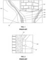
- Fig. 1 shows the different layers of such an insulation system on a façade
- Fig. 2 shows the result obtained.
- the inventor of the present invention has developed a fixing device specially designed for fixing the insulation sheets on a façade.
- this fixing device will be pre-installed on the insulation sheets by a previous industrial process.
- the installation of an insulation system formed by these sheets will be much faster and simpler compared to known conventional systems.
- the fixing device has a design composed of two physically differentiated elements that fit together and that are particularly designed for this purpose.
- distal and proximal are to be interpreted according to the meaning they usually have in the field of medicine.
- proximal refers to the side or end of an element that is closest to the person handling it, while the term “distal” refers to the side or end of an element that is farthest from the person handling it.
- the term “longitudinal” refers to the main direction along which the elements forming the fixing device of the invention extend.
- the longitudinal direction is perpendicular to the wall.
- transverse refers to any direction perpendicular to said longitudinal direction. That is, when the sheet is installed on a wall, any direction contained in a plane parallel to said wall is a transverse direction.
- the "inner surface” of the sheet of the invention refers to the surface of said sheet or layer that is oriented towards the façade on which it is to be installed.
- the “outer surface” of one such sheet or layer refers to the surface that is oriented in the opposite direction to the façade on which it is to be installed. Therefore, taking into account the definition of the terms “proximaf” and “distal”, as well as the orientation adopted by the device of the invention pre-installed inside the sheet, generally the inner surface of the sheet may be referred to as “distal surface”, and the outer surface of the sheet may be referred to as "proximal surface”.
- the invention is a fixing device for a prefabricated façade insulation sheet, i.e. for fixing an insulation sheet on the façade of a dwelling or building, according to claim 1.
- the fixing device basically comprises two elements: a stud and a stem. Each of these elements is defined in greater detail below.
- the stud comprises a head in a proximal position and a body in a distal position that protrudes transversely relative to the body. That is, the stud has a structure that can be considered similar to that of a screw or nail, with an elongated body having at a proximal end a wider head protruding in a direction transverse to the main direction of the body.
- the stud is introduced into the insulating sheet to be fixed.
- the body is embedded in the sheet perpendicular to the plane of the sheet itself, and the wider head prevents the body from completely crossing the sheet, thus anchoring the device to it.
- the head may in principle have different shapes, but preferably has an essentially circular planar shape which in this field is known as a "rosette" shape.
- the shape of the outer surface of the body can be any elongated shape that allows carrying out the described function, that is, introducing or "nailing" the body in the insulating sheet.
- the outer surface of the body could be prismatic with a hexagonal base or the like, or slightly conical to facilitate its anchoring to the sheet.
- the outer surface of the stud body is cylindrical in shape.
- a distal portion of the body i.e. the tip region of the body, has a shape that tapers distally. This embodiment could be advantageous to facilitate the introduction of the stud into the insulating sheet.
- the stud further comprises a first longitudinal through-hole of decreasing cross-section in the distal direction.
- tapeering cross-section encompasses any shape of the hole in which its cross-section tapers towards the tip, either progressively or in a punctual manner by means of a straight step (i.e. perpendicular to the longitudinal direction) or by means of a conical portion. The purpose of this narrowing is to anchor the stem inside the first longitudinal hole, in the sense of preventing the stem from passing completely through said first longitudinal hole until leaving the distal end of the stud.
- the shape of the outer surface of the stem is complementary to the shape of the inner surface of the first hole of the stud and the narrowing, in any of its possible forms, causes the stem to enter only up to a certain point where it is blocked and practically forms a single piece with the stud.
- the stem comprises a proximal portion and a distal portion traversed by a second longitudinal bore.
- the second longitudinal hole is configured to receive a screw in a manner similar to that of a conventional stud of the type used for anchoring screws or the like to a wall. It is, therefore, a hole usually cylindrical in shape and whose diameter will adjust to the diameter of the screw to be inserted.
- the proximal portion has an outer surface of decreasing cross-section in a distal direction configured to fit into the first longitudinal hole of the stud so that, when said proximal portion of the stem fits in said longitudinal hole, at least the distal portion of the stem protrudes distally from the stud. That is, as mentioned above, the shape of the outer surface of the proximal portion of the shaft and the shape of the inner surface of the stud hole are complementary. Thus, since both include a taper, be it of any type, the stem can only be introduced into the stud a certain distance from that which it is locked inside.
- the shape of the first hole of the stud and the proximal portion of the stem are designed so that it is locked inside the stud in a position such that its distal portion protrudes from the distal end of the stud.
- the first longitudinal hole of the stud and the outer surface of the proximal portion of the stem are conical in shape.
- the distal portion of the stem is configured to open when a screw is inserted along the second longitudinal hole to be anchored to a hole drilled in a wall. That is to say, the distal portion of the stem has a structure similar to that of a stud according to the conventional meaning of the term, in which the introduction of the screw causes the opening of wings, grooves, ribs or the like that prevent it, once introduced into a wall, from being able to be extracted again.
- the shape of the distal portion of the stem is essentially cylindrical, although it is also possible to have a small taper.
- the prefabricated sheet will have a series of stud embedded in that sheet, as described above, in certain positions that ensure its correct fixing to the façade.
- the sheet is presented in the desired position on the wall of the façade, on which the adhesion mortar has been previously applied, and then holes are drilled in the wall in the positions where the studs are located.
- the positions of these holes can be marked, for example, through the first longitudinal hole of each stud, or the drill bit can be directly inserted through said first longitudinal hole of each stud.
- the corresponding stems are inserted until their respective proximal portions are fitted in the first longitudinal hole of each stud.
- the distal portion of each stem is housed inside the corresponding hole made in the wall.
- a suitably sized screw is then inserted through each stem until, as it traverses the distal portion that is housed in the hole in the wall, this distal portion opens and the screw anchored to said distal portion.
- the sheet is thus fixed to the façade in a fast and safe way.
- the invention also describes a prefabricated façade insulation sheet comprising embedded therein at least one stud of a fixing device according to the type described above, oriented perpendicular to inner and outer surfaces of said prefabricated sheet, according to claim 7. That is, the sheet has preinserted a plurality of studs already ready to carry out the fixing of the sheet using the corresponding stems.
- the characteristics of the studs pre-inserted in the sheet are those described in the previous section.
- the prefabricated sheet comprises an insulation layer coated by at least one finishing layer.
- the insulating layer is responsible for thermally insulating the façade, while the finishing layer is responsible for providing the outer face of the sheet with an attractive aesthetic appearance.
- the insulating layer may be made of any insulating material commonly used in this field, such as for example EPS, rock wool, or others.
- the finishing layer which, as is known, can in turn be formed by several sub-layers. For example, it may comprise a sub-layer formed of acrylic mortar reinforced with a mesh upon which a decorative sub-layer is laid.
- the stud is embedded in the sheet in such a way that a distal end of the body of said stud is essentially flush with the inner surface of said prefabricated sheet, and a proximal surface of the head of the stud is at least partially covered by the finishing layer.
- partially covered implies that, at most, only the first longitudinal hole of each stud is visible from the outer side of the sheet, the rest of the head of the stud being completely covered by the finishing layer. That is, the stud can have a length similar to the thickness of the insulating layer of the sheet and be embedded in this insulating layer, its head being essentially flush with the outer surface of the insulating layer and, therefore, covered by the finishing layer. From the outside, only the first longitudinal holes of each stud would be visible so that the installer can subsequently insert the stems and screws during the installation process.
- the sheet further comprises a stem housed inside the first longitudinal hole of each stud and, more preferably, also comprises a screw partially housed inside the second longitudinal hole of each stem. That is, it is possible to arrange in the prefabricated sheet a plurality of complete devices, including stud, stem and optionally also the corresponding screws partially inserted, which avoids the stems being lost if only the studs are pre-inserted. Naturally, the screws would only be inserted at a small distance that would not cause the distal portion of the stem to open.
- the installation procedure of the prefabricated sheet described would be as follows.
- the sheet comprises pre-installed therein a plurality of studs configured to receive the corresponding stems and screws that allow the fixing of the sheet to the façade in question.
- These blocks can be embedded in the insulating layer of the sheet and its head covered with the finishing layer with the exception of the first longitudinal hole of each stud.
- This procedure basically comprises the following steps:
- the installation process may further involve additional steps known in this field.
- a guide rail can be fixed at the bottom of the façade and then spread a levelling adhesion mortar on the part of the façade where the sheet is to be fixed.
- a perimeter cord can also be extended over the inner surface of the sheet plus three adhesion mortar skins inside the cord.
- the holes can be plugged with insulation material and an exterior finishing product, as well as sealing the joints between adjacent sheets also with the exterior finishing product.
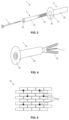
- Fig. 3 shows an exploded view of the fixing device (1) of the present invention where the different parts that comprise it can be seen.
- the device (1) is formed by a stud (2) and a stem (2).
- the stud (2) is formed by a head (21) and a body (22) that are crossed by a first longitudinal hole (23).
- the body (22) has an outer surface of cylindrical shape, while the head (21) located at its proximal end has a shape commonly known as a "rosette". This shape essentially corresponds to a flat circular shape with rounded walls in the transition area with the cylindrical surface of the body (22) and with a flat proximal side perpendicular to the longitudinal direction.
- the first longitudinal bore hole (23) has an essentially tapered shape that tapers from the proximal mouth to the distal mouth.
- the stem (3) is formed by a proximal portion (31) and a distal portion (32) which are traversed by a second longitudinal hole (33).
- the proximal portion (31) has an outer surface having a tapered shape corresponding to the tapered shape of the first longitudinal hole (23) of the stud (2). Further, the proximal portion (31) has a length which is coincident with the length of the stud (2). Thus, when the stem (3) is inserted into the stud (2), the proximal portion (31) of the stem (3) is locked inside the first longitudinal hole (23).
- the proximal end of the proximal portion (31) of the stem (3) is essentially flush with the proximal end of the stud (2), and the distal end of the proximal portion (31) of the stem (3) is essentially flush with the distal end of the stud (2).
- the proximal portion (31) of the stem (3) is thus completely housed inside the first longitudinal hole (23) of the stud (2), thus both forming a single piece for practical purposes. In this situation, the entire distal portion (32) of the stem (3) protrudes through the distal end of the stud (2).
- This distal portion (32) has a structure similar to that of a conventional stud, that is, a structure configured to be anchored to a hole made in a wall when a screw (T) is introduced through the second longitudinal hole (33) of the stem (3). Finally, this shows that the second longitudinal hole (33) of the stem (3) is configured to receive the screw (T), and is therefore normally cylindrical.
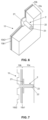
- Figures 5-7 show various views of a sheet (10) comprising a plurality of studs (2) pre-installed therein according to the present invention.
- the sheet (10) basically comprises two layers: an insulating layer (10a) and a finishing layer (10b).
- the insulating layer (10a) may be made of any suitable known material, such as rock wool.
- the finishing layer (10b) in this example is formed by two sub-layers, namely a first sub-layer (10b1) of acrylic mortar reinforced with a mesh and a second sub-layer (10b2) imitating a visible brick finish.
- the stud (2) is pre-installed in the insulating layer (10a) of the sheet (10).
- the body (22) of the stud (2) is completely embedded in said insulating layer (10a), the distal end of the body (22) being essentially flush with the inner surface of the sheet (10) and the head (21) being essentially flush with the outer surface of the insulating layer (10a).
- the finishing layer (10b) completely covers the head (21) of the stud (2) with the exception of the first longitudinal hole (23).
- the position of the studs (2) is chosen so that the position of the first longitudinal hole (2) thereof lies in the space between two bricks, more particularly in a T-joint.
- the pre-installation of the studs (2) inside the sheet (10) can be carried out in different ways.
- the studs (2) may be pre-installed in the insulation layer (10a) during the manufacture of the sheet (10) in the factory, and then the finishing layer (10b) applied with the desired characteristics (i.e., including one or the other sub-layers).
- the finishing layer (10b) can then be drilled in the positions where the studs (2) are, thus leaving the first longitudinal hole (23) of each stud (2) visible for the subsequent introduction of the stem (3) and the screw (T).
- the prefabricated sheets (10) can thus be marketed, only with the studs (2) embedded, so that the stems (3) are provided separately. Alternatively, the stems (3) and optionally the screws (T) could also be partially inserted into the studs (2).
- a guide rail is first fixed at the bottom of the façade and then a levelling adhesion mortar is spread over the part of the façade where the sheet (10) is to be fixed.
- a perimeter cord can also be extended on the inner surface of the sheet (10) plus three skins of adhesion mortar inside the cord. Once that is done, the sheet (10) is placed on the façade and fixing holes are drilled in the façade through the first longitudinal hole (23) of each stud (2).
- Respective stems (3) are then introduced thoroughly through the first longitudinal hole (23) of each stud (2), thus accommodating in the corresponding hole of the façade the distal portion (32) of each stem (3).
- Respective screws (T) are then screwed through the second longitudinal hole (33) of each stem (3) so that, when the screw (T) reaches the distal portion (32) of the stem (3), it causes the opening of the corresponding anchoring wings or structures.
- the fixing device (1) and therefore also the sheet (10), is thus firmly fixed to the façade.
- the process is completed by covering the holes through which the stem (3) and screw (T) have been inserted, or only the screw (T), with an insulating element plug and a filling of the same finishing material as the proximal part of the sheet (10), so that these holes are completely hidden.
Landscapes
- Physics & Mathematics (AREA)
- Engineering & Computer Science (AREA)
- Architecture (AREA)
- Acoustics & Sound (AREA)
- Electromagnetism (AREA)
- Civil Engineering (AREA)
- Structural Engineering (AREA)
- Building Environments (AREA)
- Joining Of Building Structures In Genera (AREA)
- Finishing Walls (AREA)
Claims (14)
- Befestigungsvorrichtung (1) für eine vorgefertigte Fassadenisolierplatte, umfassend:einen Stift (2), der einen proximal gelegenen Kopf (21) und einen distal gelegenen Körper (22) umfasst, wobei der Kopf (21) schräg vom Körper (22) absteht und der Stift (2) ein erstes durchgehendes Längsloch (23) mit einem in distaler Richtung abnehmenden Querschnitt umfasst; undeinen Stamm (3), der einen proximalen Abschnitt (31) und einen distalen Abschnitt (32) umfasst, welche von einem zweiten Längsloch durchzogen sind, wobei der proximalen Abschnitt (31) eine Außenfläche mit einem in distaler Richtung abnehmenden Querschnitt aufweist, welche so ausgelegt ist, dass sie in das erste Längsloch (23) des Stiftes (2) passt, wodurch, wenn dieser proximale Abschnitt (31) des Stammes (3) in das Längsloch (23) eingesetzt wird, mindestens der distale Abschnitt (32) des Stammes (3) distal aus dem Stift (2) hervorragt, wobei der distale Abschnitt (32) des Stammes (3) so ausgebildet ist, dass er sich aufspreizt, wenn eine Schraube (T) entlang dem zweiten Längsloch (33) eingeführt wird, um in einem in der Wand gebohrten Loch verankert zu werden,dadurch gekennzeichnet, dass das erste Längsloch (23) des Stiftes (2) eine Kegelform aufweist, die sich von einem proximalen zu einem distalen Mund verjüngt, und der proximale Abschnitt (31) des Stammes (3) eine Kegelform aufweist, die der Kegelform des ersten Längsloches (23) des Stiftes (2) entspricht, wobei eine Länge des proximalen Abschnittes (31) des Stammes (3) einer Länge des Stiftes (2) entspricht,sodass bei Einsetzen des proximalen Abschnittes (31) des Stammes (3) in das Längsloch (23) des Stiftes (2) das proximale Ende des proximalen Abschnittes (31) des Stammes (3) mit dem proximalen Ende des Stiftes (2) bündig abschließt und das distale Ende des proximalen Abschnittes (31) des Stammes (3) mit dem distalen Ende des Stiftes (2) bündig abschließt.
- Befestigungsvorrichtung (1) nach Anspruch 1, wobei eine Außenfläche des Körpers (22) des Stiftes (2) eine zylindrische Form aufweist.
- Befestigungsvorrichtung (1) nach Anspruch 2, wobei sich ein distaler Abschnitt der Außenfläche des Körpers (22) des Stiftes (2) distal verjüngt.
- Befestigungsvorrichtung (1) nach einem der vorhergehenden Ansprüche, wobei der Kopf (21) des Stiftes (2) eine im Wesentlichen angeschrägte Form aufweist.
- Befestigungsvorrichtung (1) nach einem der Ansprüche 1-3, wobei der Kopf (21) des Stiftes (2) eine im Wesentlichen kreisförmige, flache Form aufweist.
- Befestigungsvorrichtung (1) nach einem der vorhergehenden Ansprüche, wobei der distale Abschnitt (32) des Stammes (3) eine im Wesentlichen zylindrische Form aufweist.
- Vorgefertigte Fassadenisolierplatte (10) umfassend mindestens einen darin eingebetteten Stift (2) einer Befestigungsvorrichtung (1) nach einem der vorhergehenden Ansprüche, welcher senkrecht zu den Innen- und Außenflächen der genannten vorgefertigten Platte (10) ausgerichtet ist.
- Vorgefertigte Fassadenisolierplatte (10) nach Anspruch 7, wobei die vorgefertigte Platte (10) eine Isolierschicht (10a) umfasst, die von mindestens einer Deckschicht (10b) abgedeckt ist, wobei ein distales Ende des Körpers (22) des Stiftes (2) im Wesentlichen bündig mit der Innenfläche der vorgefertigten Platte (10) abschließt und eine proximale Fläche des Kopfes (21) des Stiftes (2) zumindest teilweise von der Deckschicht (10b) abgedeckt ist.
- Vorgefertigte Fassadenisolierplatte (10) nach einem der Ansprüche 7-8, weiterhin umfassend einen Stamm (3), der innerhalb des ersten Längsloches (23) jedes Stiftes (2) aufgenommen ist.
- Vorgefertigte Fassadenisolierplatte (10) nach Anspruch 9, weiterhin umfassend eine Schraube (T), die teilweise innerhalb des zweiten Längsloches (33) des Stammes (3) aufgenommen ist.
- Vorgefertigte Fassadenisolierplatte (10) nach einem der Ansprüche 8-10, wobei die Isolierschicht (10b) aus geschäumtem Polystyrol oder Steinwolle besteht.
- Vorgefertigte Fassadenisolierplatte (10) nach einem der Ansprüche 8-11, wobei die Deckschicht (10b) aus mehreren Unterschichten (10b1, 10b2) besteht.
- Vorgefertigte Fassadenisolierplatte (10) nach Anspruch 12, wobei die Deckschicht (10b) eine erste Unterschicht (10b1) aus mit Masche verstärktem Acrylmörtel umfasst, auf die eine zweite dekorative Unterschicht (10b2) aufgetragen ist.
- Vorgefertigte Fassadenisolierplatte (10) nach Anspruch 13, wobei die zweite dekorative Unterschicht (10b2) eine sichtbare Ziegelbeschichtung nachahmt.
Applications Claiming Priority (1)
| Application Number | Priority Date | Filing Date | Title |
|---|---|---|---|
| ES202230851U ES1292479Y (es) | 2022-05-21 | 2022-05-21 | Dispositivo de fijación para plancha prefabricada de aislamiento de fachada y planchaprefabricada de aislamiento de fachada que comprende dicho dispositivo de fijación |
Publications (3)
| Publication Number | Publication Date |
|---|---|
| EP4283066A1 EP4283066A1 (de) | 2023-11-29 |
| EP4283066C0 EP4283066C0 (de) | 2025-04-02 |
| EP4283066B1 true EP4283066B1 (de) | 2025-04-02 |
Family
ID=82163617
Family Applications (1)
| Application Number | Title | Priority Date | Filing Date |
|---|---|---|---|
| EP23170901.5A Active EP4283066B1 (de) | 2022-05-21 | 2023-05-01 | Befestigungsvorrichtung für vorgefertigte fassadenisolierplatte und vorgefertigte fassadenisolierplatte mit dieser befestigungsvorrichtung |
Country Status (3)
| Country | Link |
|---|---|
| EP (1) | EP4283066B1 (de) |
| ES (2) | ES1292479Y (de) |
| PL (1) | PL4283066T3 (de) |
Family Cites Families (2)
| Publication number | Priority date | Publication date | Assignee | Title |
|---|---|---|---|---|
| EP3279485A1 (de) * | 2016-08-04 | 2018-02-07 | HILTI Aktiengesellschaft | Dämmstoffanker mit partieller beschichtung |
| CN113789871A (zh) * | 2021-10-08 | 2021-12-14 | 山东国创节能科技股份有限公司 | 一种保温装饰一体化模板及墙体结构 |
-
2022
- 2022-05-21 ES ES202230851U patent/ES1292479Y/es active Active
-
2023
- 2023-05-01 ES ES23170901T patent/ES3025709T3/es active Active
- 2023-05-01 PL PL23170901.5T patent/PL4283066T3/pl unknown
- 2023-05-01 EP EP23170901.5A patent/EP4283066B1/de active Active
Also Published As
| Publication number | Publication date |
|---|---|
| EP4283066C0 (de) | 2025-04-02 |
| ES1292479U (es) | 2022-07-01 |
| EP4283066A1 (de) | 2023-11-29 |
| ES1292479Y (es) | 2022-09-22 |
| ES3025709T3 (en) | 2025-06-09 |
| PL4283066T3 (pl) | 2025-07-14 |
Similar Documents
| Publication | Publication Date | Title |
|---|---|---|
| US4653246A (en) | Insulation board for attachment to walls | |
| US10858842B2 (en) | Wall panel | |
| US9145688B2 (en) | Lath support system | |
| EP1979554B1 (de) | Fassadensystem mit markierten fugen | |
| US20100095629A1 (en) | Insulating thin-brick, thin-stone, and thin-block siding system | |
| CN104831828A (zh) | 工厂化生产装配式新型节能轻质复合板状墙体 | |
| RU2348773C2 (ru) | Способ закрепления теплоизоляционных панелей и дюбель для этого | |
| US12331510B2 (en) | Wall cladding panels, systems, and methods of installation and use | |
| AU2016342075B2 (en) | Wall panel | |
| US20050235598A1 (en) | Wall construction method | |
| EP4283066B1 (de) | Befestigungsvorrichtung für vorgefertigte fassadenisolierplatte und vorgefertigte fassadenisolierplatte mit dieser befestigungsvorrichtung | |
| JPH10280576A (ja) | 建築物外壁の断熱材と防火材の取付け構造 | |
| US20080263982A1 (en) | Insulated stone, wall structure using same and method of assembling a wall structure | |
| CN201190388Y (zh) | 一种通过内螺纹和后加锚栓固定的建筑外墙保温装饰板 | |
| CN207453352U (zh) | 一种建筑外墙装饰板的锚固结构 | |
| EP1444410A1 (de) | Wandkonstruktionsverfahren | |
| AU2002332966A1 (en) | Wall construction method | |
| JPS6222582Y2 (de) | ||
| JPH0633670B2 (ja) | 木造壁外断熱改修工法 | |
| PL241497B1 (pl) | Profil do boniowania łamanej płaszczyzny budowlanej | |
| CN111927006A (zh) | 一种茅草屋檐安装方法 | |
| CN105926781B (zh) | 防水支撑件、保温装饰一体化板、外墙外保温系统及施工方法 | |
| KR20120011581A (ko) | 역시공방법에 의한 한옥방식의 리모델링 시공방법 | |
| CN214364279U (zh) | 一种现浇一体化外墙保温系统 | |
| CN103132612A (zh) | 哑铃密足复合保温板 |
Legal Events
| Date | Code | Title | Description |
|---|---|---|---|
| PUAI | Public reference made under article 153(3) epc to a published international application that has entered the european phase |
Free format text: ORIGINAL CODE: 0009012 |
|
| STAA | Information on the status of an ep patent application or granted ep patent |
Free format text: STATUS: THE APPLICATION HAS BEEN PUBLISHED |
|
| AK | Designated contracting states |
Kind code of ref document: A1 Designated state(s): AL AT BE BG CH CY CZ DE DK EE ES FI FR GB GR HR HU IE IS IT LI LT LU LV MC ME MK MT NL NO PL PT RO RS SE SI SK SM TR |
|
| STAA | Information on the status of an ep patent application or granted ep patent |
Free format text: STATUS: REQUEST FOR EXAMINATION WAS MADE |
|
| 17P | Request for examination filed |
Effective date: 20240408 |
|
| RBV | Designated contracting states (corrected) |
Designated state(s): AL AT BE BG CH CY CZ DE DK EE ES FI FR GB GR HR HU IE IS IT LI LT LU LV MC ME MK MT NL NO PL PT RO RS SE SI SK SM TR |
|
| GRAP | Despatch of communication of intention to grant a patent |
Free format text: ORIGINAL CODE: EPIDOSNIGR1 |
|
| STAA | Information on the status of an ep patent application or granted ep patent |
Free format text: STATUS: GRANT OF PATENT IS INTENDED |
|
| RIC1 | Information provided on ipc code assigned before grant |
Ipc: E04B 1/76 20060101AFI20250103BHEP |
|
| GRAS | Grant fee paid |
Free format text: ORIGINAL CODE: EPIDOSNIGR3 |
|
| INTG | Intention to grant announced |
Effective date: 20250124 |
|
| GRAA | (expected) grant |
Free format text: ORIGINAL CODE: 0009210 |
|
| STAA | Information on the status of an ep patent application or granted ep patent |
Free format text: STATUS: THE PATENT HAS BEEN GRANTED |
|
| RAP1 | Party data changed (applicant data changed or rights of an application transferred) |
Owner name: COVERWALL, S.L. |
|
| AK | Designated contracting states |
Kind code of ref document: B1 Designated state(s): AL AT BE BG CH CY CZ DE DK EE ES FI FR GB GR HR HU IE IS IT LI LT LU LV MC ME MK MT NL NO PL PT RO RS SE SI SK SM TR |
|
| REG | Reference to a national code |
Ref country code: GB Ref legal event code: FG4D |
|
| REG | Reference to a national code |
Ref country code: CH Ref legal event code: EP |
|
| REG | Reference to a national code |
Ref country code: DE Ref legal event code: R096 Ref document number: 602023002666 Country of ref document: DE |
|
| REG | Reference to a national code |
Ref country code: IE Ref legal event code: FG4D |
|
| U01 | Request for unitary effect filed |
Effective date: 20250417 |
|
| U07 | Unitary effect registered |
Designated state(s): AT BE BG DE DK EE FI FR IT LT LU LV MT NL PT RO SE SI Effective date: 20250425 |
|
| U20 | Renewal fee for the european patent with unitary effect paid |
Year of fee payment: 3 Effective date: 20250425 |
|
| REG | Reference to a national code |
Ref country code: ES Ref legal event code: FG2A Ref document number: 3025709 Country of ref document: ES Kind code of ref document: T3 Effective date: 20250609 |
|
| PGFP | Annual fee paid to national office [announced via postgrant information from national office to epo] |
Ref country code: PL Payment date: 20250512 Year of fee payment: 3 |
|
| PGFP | Annual fee paid to national office [announced via postgrant information from national office to epo] |
Ref country code: ES Payment date: 20250603 Year of fee payment: 3 |
|
| PGFP | Annual fee paid to national office [announced via postgrant information from national office to epo] |
Ref country code: IE Payment date: 20250508 Year of fee payment: 3 |
|
| PG25 | Lapsed in a contracting state [announced via postgrant information from national office to epo] |
Ref country code: NO Free format text: LAPSE BECAUSE OF FAILURE TO SUBMIT A TRANSLATION OF THE DESCRIPTION OR TO PAY THE FEE WITHIN THE PRESCRIBED TIME-LIMIT Effective date: 20250702 |
|
| PG25 | Lapsed in a contracting state [announced via postgrant information from national office to epo] |
Ref country code: HR Free format text: LAPSE BECAUSE OF FAILURE TO SUBMIT A TRANSLATION OF THE DESCRIPTION OR TO PAY THE FEE WITHIN THE PRESCRIBED TIME-LIMIT Effective date: 20250402 |
|
| PG25 | Lapsed in a contracting state [announced via postgrant information from national office to epo] |
Ref country code: RS Free format text: LAPSE BECAUSE OF FAILURE TO SUBMIT A TRANSLATION OF THE DESCRIPTION OR TO PAY THE FEE WITHIN THE PRESCRIBED TIME-LIMIT Effective date: 20250702 |
|
| PG25 | Lapsed in a contracting state [announced via postgrant information from national office to epo] |
Ref country code: IS Free format text: LAPSE BECAUSE OF FAILURE TO SUBMIT A TRANSLATION OF THE DESCRIPTION OR TO PAY THE FEE WITHIN THE PRESCRIBED TIME-LIMIT Effective date: 20250802 |
|
| PG25 | Lapsed in a contracting state [announced via postgrant information from national office to epo] |
Ref country code: SM Free format text: LAPSE BECAUSE OF FAILURE TO SUBMIT A TRANSLATION OF THE DESCRIPTION OR TO PAY THE FEE WITHIN THE PRESCRIBED TIME-LIMIT Effective date: 20250402 |
|
| PG25 | Lapsed in a contracting state [announced via postgrant information from national office to epo] |
Ref country code: CZ Free format text: LAPSE BECAUSE OF FAILURE TO SUBMIT A TRANSLATION OF THE DESCRIPTION OR TO PAY THE FEE WITHIN THE PRESCRIBED TIME-LIMIT Effective date: 20250402 |
|
| PG25 | Lapsed in a contracting state [announced via postgrant information from national office to epo] |
Ref country code: SK Free format text: LAPSE BECAUSE OF FAILURE TO SUBMIT A TRANSLATION OF THE DESCRIPTION OR TO PAY THE FEE WITHIN THE PRESCRIBED TIME-LIMIT Effective date: 20250402 |
|
| PG25 | Lapsed in a contracting state [announced via postgrant information from national office to epo] |
Ref country code: MC Free format text: LAPSE BECAUSE OF FAILURE TO SUBMIT A TRANSLATION OF THE DESCRIPTION OR TO PAY THE FEE WITHIN THE PRESCRIBED TIME-LIMIT Effective date: 20250402 |
|
| PLBE | No opposition filed within time limit |
Free format text: ORIGINAL CODE: 0009261 |
|
| STAA | Information on the status of an ep patent application or granted ep patent |
Free format text: STATUS: NO OPPOSITION FILED WITHIN TIME LIMIT |
|
| REG | Reference to a national code |
Ref country code: CH Ref legal event code: L10 Free format text: ST27 STATUS EVENT CODE: U-0-0-L10-L00 (AS PROVIDED BY THE NATIONAL OFFICE) Effective date: 20260211 |
|
| 26N | No opposition filed |
Effective date: 20260105 |