EP4282809B1 - Verschliessmaschine zum verschliessen von flaschen mit kronenkorken - Google Patents
Verschliessmaschine zum verschliessen von flaschen mit kronenkorken Download PDFInfo
- Publication number
- EP4282809B1 EP4282809B1 EP23174172.9A EP23174172A EP4282809B1 EP 4282809 B1 EP4282809 B1 EP 4282809B1 EP 23174172 A EP23174172 A EP 23174172A EP 4282809 B1 EP4282809 B1 EP 4282809B1
- Authority
- EP
- European Patent Office
- Prior art keywords
- capping machine
- capping
- movable frame
- locking means
- bottle
- Prior art date
- Legal status (The legal status is an assumption and is not a legal conclusion. Google has not performed a legal analysis and makes no representation as to the accuracy of the status listed.)
- Active
Links
Images




Classifications
-
- B—PERFORMING OPERATIONS; TRANSPORTING
- B67—OPENING, CLOSING OR CLEANING BOTTLES, JARS OR SIMILAR CONTAINERS; LIQUID HANDLING
- B67B—APPLYING CLOSURE MEMBERS TO BOTTLES JARS, OR SIMILAR CONTAINERS; OPENING CLOSED CONTAINERS
- B67B3/00—Closing bottles, jars or similar containers by applying caps
- B67B3/02—Closing bottles, jars or similar containers by applying caps by applying flanged caps, e.g. crown caps, and securing by deformation of flanges
- B67B3/10—Capping heads for securing caps
- B67B3/12—Capping heads for securing caps characterised by being movable axially relative to cap to deform flanges thereof, e.g. to press projecting flange rims inwardly
Definitions
- the present invention relates to the field of capping machines for closing bottles with crown caps.
- These machines are also called capsuling machines, i.e., equipment for capping crown caps on the mouth of bottles.
- Said type of machine falls among those configured for small productions and is therefore generally of the manual type.
- Said machines can be table-mounted, thus configured to be placed on a raised table top, or column-mounted, thus configured to be placed on the floor.
- the known machines comprise a base with a metal column on which the capping mechanism is installed.
- the capping mechanism generally comprises a manoeuvring lever adapted to operate a head to which it imparts a vertical motion and a pressure force which is transferred to the crown cap placed on the mouth of the bottle to be capped.
- Said capsuling machines are expensive both in terms of assembly and production, as they are made from several metal parts.
- said capsuling machines have large dimensions which are not compatible with insertion, for example, inside fermenters in beer kits.
- Document IT1137747 describes a capping machine for hermetically sealing bottles of various sizes with crown caps.
- Said machine comprises a base from which two uprights rise, joined together vertically by a semi-cylindrical surface inside of which are a series of grooves are obtained, arranged at different heights, adapted to receive a plate which can be inserted to position bottles of different heights at the correct height with respect to the capping mechanism; concentric circular seats of different diameters are obtained in said plate for positioning the base of bottles of different diameters.
- the axis of the bottle may be inclined with respect to the pressure force of the capping head, which has a vertical direction.
- the wear of the grooves and/or the plate over time means that the machine cannot ensure a stable support for the bottle.
- Document CN 108 751 087 describes a capping machine in accordance with the preamble of claim 1.
- the technical problem at the basis of the present invention is that of providing a capping machine for closing bottles with crown caps which is structurally and functionally designed to overcome one or more of the limits set out above with reference to the prior art.
- a main aim of the invention is to develop a capping machine for closing bottles with crown caps, as part of a flexible solution which allows to reliably work with bottles of different heights and sizes.
- a further aim of the invention is also that of providing the art with a manual capping machine for closing bottles with crown caps, within the scope of a simple and rational solution, with limited size and cost.
- Said machine comprises a base, on which a bottom of the bottle rests.
- a fixed frame comprising two uprights inside which the bottle to be capped is positioned, and a movable frame at the top of which a capping mechanism is integrated.
- Such a capping mechanism comprises a manoeuvring lever adapted to operate a head by imparting a vertical motion and a pressure force to said head which is transferred to the crown cap arranged on the mouth of the bottle to be capped.
- Said movable frame is configured to be manually translated in a vertical direction along the fixed frame so as to bring the capping mechanism to the correct working height according to the height of the bottle to be capped.
- said capping machine comprises locking means of a removable type, configured to engage/disengage simultaneously with the movable frame and with the fixed frame to lock said movable frame in the working position.
- said locking means are engaged by insertion into the movable and fixed frame in a direction orthogonal to the vertical capping direction.
- the two uprights are configured to slidably receive two columns of the movable frame.
- the two columns of the movable frame externally embrace the two uprights of the fixed frame.
- the columns of the movable frame are internally hollow so as to contain therein the upright along which they can slide in a vertical direction.
- the columns of the movable frame and the uprights of the fixed frame comprise a flat face, preferably facing the inside of the capping machine.
- the locking means comprise at least one protrusion adapted to fit into a corresponding outer recess of the movable frame and into a corresponding inner recess of the fixed frame.
- said outer recess is made on at least one column of the movable frame and said inner recess is made on at least one upright of the fixed frame.
- the locking means comprise at least one pair of protrusions, adapted to fit into at least one pair of corresponding outer recesses, located on both uprights columns and into at least one pair of corresponding inner recesses, located on both uprights.
- each column comprises a number of outer recesses equal to the number of pairs of protrusions.
- each upright comprises a plurality of inner recesses distributed along the height of each upright.
- the inner recesses are arranged in pitch on each upright and preferably said pitch is constant and equal to the vertical distance between the pairs of protrusions, of the locking means.
- said inner recesses and said outer recesses are arranged towards the inside of the capping machine.
- said inner recesses are holes preferably passing through the entire width of the uprights.
- said holes have a first opening extending along the entire depth of the hole and facing the inside of the capping machine, preferably up to the flat faces.
- said outer recesses are holes passing through the entire width of the columns.
- said holes have a second opening extending along the entire depth of the hole and facing the inside of the capping machine, preferably up to the flat faces.
- the locking means comprise a connection element for connecting the protrusions of each pair with each other.
- connection element comprises an extension for connecting all the pairs of protrusions with each other.
- the locking means are further configured for positioning the bottle in axis with the capping mechanism.
- connection element comprises a curved inner surface to contact the outer surface of the bottle placed in the capping position.
- the locking means comprise adjustment means for adjusting the position thereof in a horizontal direction and to allow positioning the bottle in axis with the capping mechanism.
- the adjustment means comprise a plurality of recessed seats preferably located on the connection element.
- Said seats are preferably configured to cooperate with a relief located on the flat face of the columns facing the inside of the capping machine.
- the movable frame preferably comprises a crossbar, in which the capping mechanism is arranged.
- the crossbar connects the columns of the movable frame above and is preferably curved.
- the fixed frame and/or the movable frame and/or the locking means are made of plastic.
- Figure 1 depicts a capping machine 100 for closing bottles 200 with crown caps 250.
- Said machine in particular comprises a base 15, on which a bottom 203 of the bottle 200 rests.
- the machine generally comprises a fixed frame 10 and a movable frame 20.
- the fixed frame 10 comprises two uprights 11, 12 inside which the bottle 200 to be capped is positioned.
- Said machines generally comprise a capping mechanism 50 comprising a manoeuvring lever 51 adapted to operate a head 55, imparting a vertical motion and a pressure force to said head 55 which is transferred to the crown cap 250 arranged on the mouth 201 of the bottle 200 to be capped.
- Said capping mechanism 50 is placed on the top of the machine 100.
- the capping mechanism 50 comprises an engagement element 54 between the manoeuvring lever 51 of the head 55, preferably made of plastic, which transfers the pressure force exerted by the lever 51 to the crown cap 250.
- the capping mechanism 50 comprises a fulcrum 53, around which the lever 51 rotates.
- It may further comprise an elastic element 52, preferably a spring, which facilitates the return of the lever 51 to the initial position.
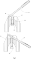
- Figure 7 depicts a sectional view of the 50 capping mechanism, in particular in the two working steps:
- the object of the invention envisages that said capping mechanism 50 is integrated at the top of the movable frame 20.
- said movable frame 20 is configured to be manually translated in a vertical direction along the fixed frame 10 so as to bring the capping mechanism 50 to the correct working height according to the height of the bottle 200 to be capped.
- the capping machine 100 adapts to the height of the bottle 200 to be capped.
- the bottles 200 can have different heights, e.g., the machine 100 can tap bottles 200 of beer from 25 to 66 cc. with a crown cap diameter of 26.
- the machine can also process wine bottle sizes up to a height of 313 mm.
- the capping mechanism 50 at the top of the movable frame 20 moves away from the base 15, allowing the insertion of a tall bottle 200.
- the capping mechanism 50 at the top of the movable frame 20 moves closer to the base 15, allowing the insertion and capping of a short bottle 200.
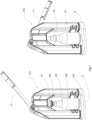
- Figures 1 and 2 show the capping machine 100 in the positioning and capping step with two bottles 200 of different heights.
- the movable frame 20 in fig. 1 is in a lowered position close to the base 15, to work with a short bottle, while the movable frame 20 in fig. 2 is in a raised position away from the base 15, to work with a tall bottle.
- said movable frame 20 can be locked in said working position by means of the insertion of locking means 30.
- the capping machine 100 preferably comprises said locking means 30, of a removable type.
- said locking means 30 are configured to engage/disengage simultaneously with the movable frame 20 and with the fixed frame 10.
- the locking means 30 are engaged by insertion or mating in the movable 20 and fixed 10 frame in a direction orthogonal to the vertical capping direction.
- the two uprights 11, 12 are configured to slidably receive two columns 21, 22 of the movable frame 20.
- said uprights 11, 12 are integral with the base 15 and preferably made in one piece.
- the uprights 11, 12, and base 15 are made of plastic material, preferably obtained by moulding.
- the uprights 11, 12 as depicted in the figure are made with lattice ribs along their entire length. This reduces the amount of material used and therefore the weight, while ensuring good mechanical strength.
- the two columns 21, 22 of the movable frame 20 externally embrace the two uprights 11, 12 of the fixed frame 10.
- the movable frame 20 is outside the fixed frame 10.
- the columns 21, 22 of the movable frame 20 are internally hollow so as to contain therein the upright 11, 12 along which they can slide in a vertical direction.
- the columns 21, 22 of the movable frame 20 and the uprights 11, 12 of the fixed frame 10 comprise a flat face 11s, 12s, 21s, 22s.
- said flat face 11s, 12s, 21s, 22s faces the inside of the capping machine 100.
- a preferred embodiment envisages that the movable frame 20 comprises a crossbar 25 in which the capping mechanism 50 is arranged.
- Said crossbar 25 preferably connects the columns 21, 22 of the movable frame 20 above and is preferably curved.
- the crossbar 25 and columns 21, 22 are made in one piece.
- the columns 21, 22 and the crossbar 25 are made of plastic material, preferably obtained by moulding.
- the locking means 30 comprise at least one protrusion 31 adapted to fit into a corresponding outer recess 23 of the movable frame 20 and into a corresponding inner recess 13 of the fixed frame 10.
- said outer recess 23 is made on at least one column 21, 22 of the movable frame 20.
- said inner recess 13 is made on at least one upright 11, 12 of the fixed frame 10.
- the locking means 30 comprise at least one pair of protrusions 310, adapted to fit into at least one pair of corresponding outer recesses 230, located on both columns 21, 22 and into at least one pair of corresponding inner recesses 130, located on both uprights 11, 12.
- the pair 310 comprises two protrusions 31, each engaging with a respective upright 11, 12 and a respective column 21, 22.
- the solution with two pairs of protrusions 310 ensures greater stability of the locking means 30, reducing possible rotations due to the construction and assembly tolerances of the protrusions 31, and of the inner recesses 13, and outer recesses 23.
- the protrusions 31 of the pairs 310 are preferably all the same.
- outer recesses 23 and inner recesses 13 of the pairs of recesses 230 and 130 are preferably all the same.
- each column 21, 22 comprises a number of outer recesses 23 equal to the number of pairs of protrusions 310, of the locking means 30.
- each column 21, 22 will comprise two outer recesses 23.
- each upright 11, 12 can comprise a plurality of inner recesses 13 distributed along the height of each upright 11, 12.
- Said inner recesses 13 are preferably arranged in pitch with each other.
- the pitch between the inner recesses 13 on each upright 11, 12 is constant and equal to the vertical distance between the pairs of protrusions 310 of the locking means 30.
- Said constant pitch allows a greater number of possible positionings of the locking means 30.
- said inner recesses 13 and said outer recesses 23 are arranged towards the inside of the capping machine 100.
- they can be positioned at the flat faces 11s, 12s, 21s, 22s.
- said inner recesses 13 are inner holes 14.
- said internal holes 14 are passing through the entire width of the uprights 11, 12.
- said inner holes 14 bear a first opening 14a extending along the entire depth of the inner hole 14.
- said first opening 14a faces towards the inside of the capping machine 100, preferably up to the flat faces 11s, 12s, of the uprights 11, 12.
- outer recesses 23 are outer holes 24.
- said outer holes 24 are passing through the entire width of the columns 21, 22.
- outer holes 24 bear a second opening 24a extending along the entire depth of the outer hole 24.
- said second opening 24a faces towards the inside of the capping machine 100, preferably up to the flat faces 21s, 22s of the columns 21, 22.
- the locking means 30 comprise a connection element 32 for connecting the protrusions of each pair 310 with each other.
- connection element 32 comprises an extension 32a connecting the two pairs 310 located one above the other.
- said locking means 30 can comprise at each protrusion 31, a rib 33 connecting the connection element 32 to the protrusion 31.
- Said rib 33 preferably extends along the entire length of the protrusion 31.
- the protrusion is not cantilevered, but supported along its entire length by the connection element 32 and is therefore more robust and less prone to deformation and breakage.
- the locking means 30 are configured to facilitate the positioning of the bottle 200 in axis with the capping mechanism 50.
- connection element 32 comprises an inner surface 32b which is curved so as to engage in contact with the outer surface 202 of the bottle 200 located in the capping position.
- the locking means 30 comprise adjustment means 35.
- Said adjustment means 35 allow to adjustment the position thereof in the horizontal direction for the positioning of the bottle 200 in axis with the capping mechanism 50.
- adjustment means 35 comprise a plurality of seats 34, preferably recessed.
- said seats 34 are on the connection element 32
- the seats 34 are made on the extension 32a comprised between the ribs 33.
- Said seats 34 are configured to cooperate with a relief 26 located on the flat face 21s, 22s of the columns 21, 22 facing the inside of the capping machine 100.
- Said seats 34 are preferably at a constant pitch from each other to allow a step positioning of the locking means 30.
- the locking means 30 are made of plastic material, preferably obtained by moulding.
Landscapes
- Engineering & Computer Science (AREA)
- Mechanical Engineering (AREA)
- Sealing Of Jars (AREA)
Claims (13)
- Verschließmaschine (100) zum Verschließen von Flaschen (200) mit Kronkorken (250), die eine Basis (15) umfasst, auf der ein Boden (203) der Flasche (200) anliegt, einen festen Rahmen (10) mit zwei Pfosten (11, 12), in denen die zu verschließende Flasche (200) positioniert ist, und einen beweglichen Rahmen (20), an dessen Oberseite ein Verschließmechanismus (50) integriert ist, der einen Steuerhebel (51) umfasst, der dazu geeignet ist, einen Kopf (55) zu betätigen, indem er dem Kopf (55) eine vertikale Bewegung und eine Druckkraft verleiht, die auf den Kronkorken (250) übertragen wird, der auf der Mündung (201) der zu verschließenden Flasche (200) angeordnet ist, wobei der bewegliche Rahmen (20) dazu konfiguriert ist, manuell in vertikaler Richtung entlang des festen Rahmens (10) verschoben zu werden, um den Verschließmechanismus (50) entsprechend der Höhe der zu verschließenden Flasche (200) auf die richtige Arbeitshöhe zu bringen, dadurch gekennzeichnet, dass die Verschließmaschine (100) Verriegelungsmittel (30) eines abnehmbaren Typs umfasst, die so konfiguriert sind, dass sie gleichzeitig mit dem beweglichen Rahmen (20) und mit dem festen Rahmen (10) in Eingriff gebracht/gelöst werden, um den beweglichen Rahmen (20) in der Arbeitsposition zu verriegeln.
- Verschließmaschine (100) gemäß Anspruch 2, wobei die Verriegelungsmittel (30) durch Einführen in den beweglichen (20) und den festen (10) Rahmen in einer Richtung orthogonal zur vertikalen Verschließrichtung in Eingriff gebracht werden.
- Verschließmaschine (100) gemäß einem der vorhergehenden Ansprüche, wobei die beiden Pfosten (11, 12) so konfiguriert sind, dass sie zwei Säulen (21, 22) des beweglichen Rahmens (20) verschiebbar aufnehmen.
- Verschließmaschine (100) nach Anspruch 3, wobei die Säulen (21, 22) des beweglichen Rahmens (20) innen hohl sind, um darin die Pfosten (11, 12) aufzunehmen, entlang derer sie in vertikaler Richtung gleiten können, und wobei vorzugsweise die Säulen (21, 22) des beweglichen Rahmens (20) und die Pfosten (11, 12) des festen Rahmens (10) eine plane Fläche (11s, 12s, 21s, 22s) aufweisen, die vorzugsweise zur Innenseite der Verschließmaschine (100) weist.
- Verschließmaschine (100) nach einem der vorhergehenden Ansprüche, wobei die Verriegelungsmittel (30) mindestens einen Vorsprung (31) umfassen, der so angepasst ist, dass er in eine entsprechende äußere Aussparung (23) des beweglichen Rahmens (20) und in eine entsprechende innere Aussparung (13) des festen Rahmens (10) passt, wobei die äußere Aussparung (23) vorzugsweise an mindestens einer Säule (21, 22) des beweglichen Rahmens (20) und die innere Aussparung (13) an mindestens einem Pfosten (11, 12) des festen Rahmens (10) angebracht ist.
- Verschließmaschine (100) nach einem der vorhergehenden Ansprüche, wobei die Verriegelungsmittel (30) mindestens ein Paar Vorsprünge (310) umfassen, die so angepasst sind, dass sie in mindestens ein Paar entsprechender äußerer Aussparungen (230) passen, die sich an beiden Pfosten (21, 22) befinden, und in mindestens ein Paar entsprechender innerer Aussparungen (130), die sich an beiden Pfosten (11, 12) befinden.
- Verschließmaschine (100) nach einem der Ansprüche 3 bis 6, wobei jede Säule (21, 22) eine Anzahl von äußeren Aussparungen (23) aufweist, die der Anzahl von Vorsprungspaaren (310) der Verriegelungseinrichtung (30) entspricht.
- Verschließmaschine (100) nach einem der vorhergehenden Ansprüche, wobei jeder Pfosten (11, 12) eine Vielzahl von inneren Aussparungen (13) aufweist, die entlang der Höhe jedes Pfostens (11, 12) verteilt sind.
- Verschließmaschine (100) nach Anspruch 8, wobei die inneren Aussparungen (13) in einem Abstand an jedem Pfosten (11, 12) angeordnet sind und dieser Abstand vorzugsweise konstant und gleich dem vertikalen Abstand zwischen den Vorsprungspaaren (310) der Verriegelungsmittel (30) ist.
- Verschließmaschine (100) nach Anspruch 6, wobei die Verriegelungsmittel (30) ein Verbindungselement (32) zum Verbinden der Vorsprünge jedes Paars (310) miteinander umfassen, und wobei das Verbindungselement (32) vorzugsweise eine Verlängerung (32a) zum Verbinden aller Paare von Vorsprüngen (310) miteinander umfasst.
- Verschließmaschine (100) nach einem der vorhergehenden Ansprüche, wobei die Verriegelungsmittel (30) ferner zum Positionieren der Flasche (200) in einer Achse mit dem Verschließmechanismus (50) konfiguriert sind, und wobei insbesondere das Verbindungselement (32) eine gekrümmte Innenfläche (32b) zum Kontaktieren der Außenfläche (202) der in der Verschließposition platzierten Flasche (200) umfasst.
- Verschließmaschine (100) nach einem der vorhergehenden Ansprüche, wobei die Verriegelungsmittel (30) Einstellmittel (35) zum Einstellen ihrer Position in horizontaler Richtung und zum Ermöglichen der Positionierung der Flasche (200) in Achse mit dem Verschließmechanismus (50) umfassen.
- Verschließmaschine (100) nach Anspruch 12, wobei die Einstellmittel (35) eine Vielzahl von vertieften Sitzen (34) umfassen, die sich vorzugsweise am Verbindungselement (32) befinden, wobei die Sitze (34) so konfiguriert sind, dass sie mit einem Vorsprung (26) zusammenwirken, der sich an der flachen Seite (21s, 22s) der Säulen (21, 22) befindet, die der Innenseite der Verschließmaschine (100) zugewandt ist.
Applications Claiming Priority (1)
| Application Number | Priority Date | Filing Date | Title |
|---|---|---|---|
| IT102022000010406A IT202200010406A1 (it) | 2022-05-19 | 2022-05-19 | Macchina tappatrice per la chiusura di bottiglie con tappi di tipo corona |
Publications (3)
| Publication Number | Publication Date |
|---|---|
| EP4282809A1 EP4282809A1 (de) | 2023-11-29 |
| EP4282809B1 true EP4282809B1 (de) | 2025-02-12 |
| EP4282809C0 EP4282809C0 (de) | 2025-02-12 |
Family
ID=82781030
Family Applications (1)
| Application Number | Title | Priority Date | Filing Date |
|---|---|---|---|
| EP23174172.9A Active EP4282809B1 (de) | 2022-05-19 | 2023-05-18 | Verschliessmaschine zum verschliessen von flaschen mit kronenkorken |
Country Status (2)
| Country | Link |
|---|---|
| EP (1) | EP4282809B1 (de) |
| IT (1) | IT202200010406A1 (de) |
Family Cites Families (2)
| Publication number | Priority date | Publication date | Assignee | Title |
|---|---|---|---|---|
| IT1137747B (it) | 1981-07-23 | 1986-09-10 | Rigamonti Pietro & Figli | Macchina tappatrice a due montanti per la chiusura ermetica di bottiglie e bottiglioni con tappi di tipo corona |
| CN108751087A (zh) * | 2018-09-04 | 2018-11-06 | 常爱兵 | 高度可调型啤酒瓶盖压盖器 |
-
2022
- 2022-05-19 IT IT102022000010406A patent/IT202200010406A1/it unknown
-
2023
- 2023-05-18 EP EP23174172.9A patent/EP4282809B1/de active Active
Also Published As
| Publication number | Publication date |
|---|---|
| IT202200010406A1 (it) | 2023-11-19 |
| EP4282809C0 (de) | 2025-02-12 |
| EP4282809A1 (de) | 2023-11-29 |
Similar Documents
| Publication | Publication Date | Title |
|---|---|---|
| US11104395B2 (en) | Dropper post assembly for a bicycle | |
| JP3834065B2 (ja) | 容器にネックを形成するための食い違い配置されたダイ方法と装置 | |
| KR20170023146A (ko) | 가정용 탄산수 기계에서의 압력 자동 방출 | |
| EP4282809A1 (de) | Verschliessmaschine zum verschliessen von flaschen mit kronenkorken | |
| MX2008014565A (es) | Metodo y dispositivo para elaborar botella rellena de contenido. | |
| AU2021378474A9 (en) | Carbonator of user-friendly design and method of carbonating a beverage | |
| US20170051869A1 (en) | Lifting Holder Structure | |
| KR101199582B1 (ko) | 용기 성형용 프레스 장치의 하부 지지 구조체 | |
| CN211770187U (zh) | 一种泵头定位旋盖头 | |
| CN209288679U (zh) | 分段式压装设备 | |
| KR102235503B1 (ko) | 캔실링기 | |
| CN210253760U (zh) | 一种文丘里阀制作模具的锁模装置 | |
| JP5205637B2 (ja) | 合成樹脂製ボトルの底部凹入装置 | |
| KR20250111118A (ko) | 음료수 병에 대해 이중 밀봉 기능이 있는 음료수 병 마개 | |
| CN116900608B (zh) | 一种汽车配件焊接装置 | |
| CN220291839U (zh) | 一种定子冲片堆叠组件 | |
| KR20200127605A (ko) | 캔 실링기의 승강장치 | |
| CN220463819U (zh) | 用于安装转向器的托盘组件 | |
| JP5140094B2 (ja) | チューブ容器用シール部面取り装置 | |
| CN221544113U (zh) | 一种瓶盖气动封盖机 | |
| KR101474707B1 (ko) | 맨홀용 라이너의 형상 교정기 | |
| CN220825399U (zh) | 一种封头压边圈用等高调节机构及冲压机构 | |
| CN221459823U (zh) | 一种搓盖式瓶盖旋盖机 | |
| CN114211240B (zh) | 球阀半自动组装设备中阀杆的整形机构 | |
| CN221269383U (zh) | 一种用于罐体的立式滚筋装置 |
Legal Events
| Date | Code | Title | Description |
|---|---|---|---|
| PUAI | Public reference made under article 153(3) epc to a published international application that has entered the european phase |
Free format text: ORIGINAL CODE: 0009012 |
|
| STAA | Information on the status of an ep patent application or granted ep patent |
Free format text: STATUS: THE APPLICATION HAS BEEN PUBLISHED |
|
| AK | Designated contracting states |
Kind code of ref document: A1 Designated state(s): AL AT BE BG CH CY CZ DE DK EE ES FI FR GB GR HR HU IE IS IT LI LT LU LV MC ME MK MT NL NO PL PT RO RS SE SI SK SM TR |
|
| STAA | Information on the status of an ep patent application or granted ep patent |
Free format text: STATUS: REQUEST FOR EXAMINATION WAS MADE |
|
| 17P | Request for examination filed |
Effective date: 20240528 |
|
| RBV | Designated contracting states (corrected) |
Designated state(s): AL AT BE BG CH CY CZ DE DK EE ES FI FR GB GR HR HU IE IS IT LI LT LU LV MC ME MK MT NL NO PL PT RO RS SE SI SK SM TR |
|
| P01 | Opt-out of the competence of the unified patent court (upc) registered |
Free format text: CASE NUMBER: APP_33549/2024 Effective date: 20240605 |
|
| RIC1 | Information provided on ipc code assigned before grant |
Ipc: B67B 3/12 20060101AFI20240718BHEP |
|
| GRAP | Despatch of communication of intention to grant a patent |
Free format text: ORIGINAL CODE: EPIDOSNIGR1 |
|
| STAA | Information on the status of an ep patent application or granted ep patent |
Free format text: STATUS: GRANT OF PATENT IS INTENDED |
|
| INTG | Intention to grant announced |
Effective date: 20240904 |
|
| GRAS | Grant fee paid |
Free format text: ORIGINAL CODE: EPIDOSNIGR3 |
|
| GRAA | (expected) grant |
Free format text: ORIGINAL CODE: 0009210 |
|
| STAA | Information on the status of an ep patent application or granted ep patent |
Free format text: STATUS: THE PATENT HAS BEEN GRANTED |
|
| AK | Designated contracting states |
Kind code of ref document: B1 Designated state(s): AL AT BE BG CH CY CZ DE DK EE ES FI FR GB GR HR HU IE IS IT LI LT LU LV MC ME MK MT NL NO PL PT RO RS SE SI SK SM TR |
|
| REG | Reference to a national code |
Ref country code: GB Ref legal event code: FG4D |
|
| REG | Reference to a national code |
Ref country code: CH Ref legal event code: EP |
|
| REG | Reference to a national code |
Ref country code: DE Ref legal event code: R096 Ref document number: 602023001979 Country of ref document: DE |
|
| REG | Reference to a national code |
Ref country code: IE Ref legal event code: FG4D |
|
| U01 | Request for unitary effect filed |
Effective date: 20250312 |
|
| P04 | Withdrawal of opt-out of the competence of the unified patent court (upc) registered |
Free format text: CASE NUMBER: APP_13209/2025 Effective date: 20250317 |
|
| U07 | Unitary effect registered |
Designated state(s): AT BE BG DE DK EE FI FR IT LT LU LV MT NL PT RO SE SI Effective date: 20250320 |
|
| PG25 | Lapsed in a contracting state [announced via postgrant information from national office to epo] |
Ref country code: RS Free format text: LAPSE BECAUSE OF FAILURE TO SUBMIT A TRANSLATION OF THE DESCRIPTION OR TO PAY THE FEE WITHIN THE PRESCRIBED TIME-LIMIT Effective date: 20250512 |
|
| PG25 | Lapsed in a contracting state [announced via postgrant information from national office to epo] |
Ref country code: PL Free format text: LAPSE BECAUSE OF FAILURE TO SUBMIT A TRANSLATION OF THE DESCRIPTION OR TO PAY THE FEE WITHIN THE PRESCRIBED TIME-LIMIT Effective date: 20250212 |
|
| U20 | Renewal fee for the european patent with unitary effect paid |
Year of fee payment: 3 Effective date: 20250530 |
|
| PG25 | Lapsed in a contracting state [announced via postgrant information from national office to epo] |
Ref country code: ES Free format text: LAPSE BECAUSE OF FAILURE TO SUBMIT A TRANSLATION OF THE DESCRIPTION OR TO PAY THE FEE WITHIN THE PRESCRIBED TIME-LIMIT Effective date: 20250212 |
|
| PG25 | Lapsed in a contracting state [announced via postgrant information from national office to epo] |
Ref country code: IS Free format text: LAPSE BECAUSE OF FAILURE TO SUBMIT A TRANSLATION OF THE DESCRIPTION OR TO PAY THE FEE WITHIN THE PRESCRIBED TIME-LIMIT Effective date: 20250612 Ref country code: NO Free format text: LAPSE BECAUSE OF FAILURE TO SUBMIT A TRANSLATION OF THE DESCRIPTION OR TO PAY THE FEE WITHIN THE PRESCRIBED TIME-LIMIT Effective date: 20250512 |
|
| PG25 | Lapsed in a contracting state [announced via postgrant information from national office to epo] |
Ref country code: HR Free format text: LAPSE BECAUSE OF FAILURE TO SUBMIT A TRANSLATION OF THE DESCRIPTION OR TO PAY THE FEE WITHIN THE PRESCRIBED TIME-LIMIT Effective date: 20250212 |
|
| PG25 | Lapsed in a contracting state [announced via postgrant information from national office to epo] |
Ref country code: GR Free format text: LAPSE BECAUSE OF FAILURE TO SUBMIT A TRANSLATION OF THE DESCRIPTION OR TO PAY THE FEE WITHIN THE PRESCRIBED TIME-LIMIT Effective date: 20250513 |
|
| PG25 | Lapsed in a contracting state [announced via postgrant information from national office to epo] |
Ref country code: SM Free format text: LAPSE BECAUSE OF FAILURE TO SUBMIT A TRANSLATION OF THE DESCRIPTION OR TO PAY THE FEE WITHIN THE PRESCRIBED TIME-LIMIT Effective date: 20250212 |
|
| PG25 | Lapsed in a contracting state [announced via postgrant information from national office to epo] |
Ref country code: CZ Free format text: LAPSE BECAUSE OF FAILURE TO SUBMIT A TRANSLATION OF THE DESCRIPTION OR TO PAY THE FEE WITHIN THE PRESCRIBED TIME-LIMIT Effective date: 20250212 |
|
| PG25 | Lapsed in a contracting state [announced via postgrant information from national office to epo] |
Ref country code: SK Free format text: LAPSE BECAUSE OF FAILURE TO SUBMIT A TRANSLATION OF THE DESCRIPTION OR TO PAY THE FEE WITHIN THE PRESCRIBED TIME-LIMIT Effective date: 20250212 |
|
| PLBE | No opposition filed within time limit |
Free format text: ORIGINAL CODE: 0009261 |
|
| STAA | Information on the status of an ep patent application or granted ep patent |
Free format text: STATUS: NO OPPOSITION FILED WITHIN TIME LIMIT |
|
| 26N | No opposition filed |
Effective date: 20251113 |
|
| PG25 | Lapsed in a contracting state [announced via postgrant information from national office to epo] |
Ref country code: MC Free format text: LAPSE BECAUSE OF FAILURE TO SUBMIT A TRANSLATION OF THE DESCRIPTION OR TO PAY THE FEE WITHIN THE PRESCRIBED TIME-LIMIT Effective date: 20250212 |
|
| PG25 | Lapsed in a contracting state [announced via postgrant information from national office to epo] |
Ref country code: IE Free format text: LAPSE BECAUSE OF NON-PAYMENT OF DUE FEES Effective date: 20250518 |