EP4282636A2 - Transfer apparatus and method for transferring one or more plies onto a carcass package on a tire building drum - Google Patents
Transfer apparatus and method for transferring one or more plies onto a carcass package on a tire building drum Download PDFInfo
- Publication number
- EP4282636A2 EP4282636A2 EP23202497.6A EP23202497A EP4282636A2 EP 4282636 A2 EP4282636 A2 EP 4282636A2 EP 23202497 A EP23202497 A EP 23202497A EP 4282636 A2 EP4282636 A2 EP 4282636A2
- Authority
- EP
- European Patent Office
- Prior art keywords
- plies
- radial distance
- ring segment
- transfer apparatus
- rolling device
- Prior art date
- Legal status (The legal status is an assumption and is not a legal conclusion. Google has not performed a legal analysis and makes no representation as to the accuracy of the status listed.)
- Granted
Links
Images


Classifications
-
- B—PERFORMING OPERATIONS; TRANSPORTING
- B29—WORKING OF PLASTICS; WORKING OF SUBSTANCES IN A PLASTIC STATE IN GENERAL
- B29D—PRODUCING PARTICULAR ARTICLES FROM PLASTICS OR FROM SUBSTANCES IN A PLASTIC STATE
- B29D30/00—Producing pneumatic or solid tyres or parts thereof
- B29D30/06—Pneumatic tyres or parts thereof (e.g. produced by casting, moulding, compression moulding, injection moulding, centrifugal casting)
- B29D30/08—Building tyres
- B29D30/20—Building tyres by the flat-tyre method, i.e. building on cylindrical drums
-
- B—PERFORMING OPERATIONS; TRANSPORTING
- B29—WORKING OF PLASTICS; WORKING OF SUBSTANCES IN A PLASTIC STATE IN GENERAL
- B29D—PRODUCING PARTICULAR ARTICLES FROM PLASTICS OR FROM SUBSTANCES IN A PLASTIC STATE
- B29D30/00—Producing pneumatic or solid tyres or parts thereof
- B29D30/06—Pneumatic tyres or parts thereof (e.g. produced by casting, moulding, compression moulding, injection moulding, centrifugal casting)
- B29D30/08—Building tyres
- B29D30/20—Building tyres by the flat-tyre method, i.e. building on cylindrical drums
- B29D30/24—Drums
- B29D30/26—Accessories or details, e.g. membranes, transfer rings
- B29D30/2607—Devices for transferring annular tyre components during the building-up stage, e.g. from the first stage to the second stage building drum
-
- B—PERFORMING OPERATIONS; TRANSPORTING
- B29—WORKING OF PLASTICS; WORKING OF SUBSTANCES IN A PLASTIC STATE IN GENERAL
- B29D—PRODUCING PARTICULAR ARTICLES FROM PLASTICS OR FROM SUBSTANCES IN A PLASTIC STATE
- B29D30/00—Producing pneumatic or solid tyres or parts thereof
- B29D30/06—Pneumatic tyres or parts thereof (e.g. produced by casting, moulding, compression moulding, injection moulding, centrifugal casting)
- B29D30/08—Building tyres
- B29D30/20—Building tyres by the flat-tyre method, i.e. building on cylindrical drums
- B29D30/30—Applying the layers; Guiding or stretching the layers during application
-
- B—PERFORMING OPERATIONS; TRANSPORTING
- B29—WORKING OF PLASTICS; WORKING OF SUBSTANCES IN A PLASTIC STATE IN GENERAL
- B29D—PRODUCING PARTICULAR ARTICLES FROM PLASTICS OR FROM SUBSTANCES IN A PLASTIC STATE
- B29D30/00—Producing pneumatic or solid tyres or parts thereof
- B29D30/06—Pneumatic tyres or parts thereof (e.g. produced by casting, moulding, compression moulding, injection moulding, centrifugal casting)
- B29D30/08—Building tyres
- B29D30/20—Building tyres by the flat-tyre method, i.e. building on cylindrical drums
- B29D30/24—Drums
-
- B—PERFORMING OPERATIONS; TRANSPORTING
- B29—WORKING OF PLASTICS; WORKING OF SUBSTANCES IN A PLASTIC STATE IN GENERAL
- B29D—PRODUCING PARTICULAR ARTICLES FROM PLASTICS OR FROM SUBSTANCES IN A PLASTIC STATE
- B29D30/00—Producing pneumatic or solid tyres or parts thereof
- B29D30/06—Pneumatic tyres or parts thereof (e.g. produced by casting, moulding, compression moulding, injection moulding, centrifugal casting)
- B29D30/08—Building tyres
- B29D30/20—Building tyres by the flat-tyre method, i.e. building on cylindrical drums
- B29D30/24—Drums
- B29D30/26—Accessories or details, e.g. membranes, transfer rings
-
- B—PERFORMING OPERATIONS; TRANSPORTING
- B29—WORKING OF PLASTICS; WORKING OF SUBSTANCES IN A PLASTIC STATE IN GENERAL
- B29D—PRODUCING PARTICULAR ARTICLES FROM PLASTICS OR FROM SUBSTANCES IN A PLASTIC STATE
- B29D30/00—Producing pneumatic or solid tyres or parts thereof
- B29D30/06—Pneumatic tyres or parts thereof (e.g. produced by casting, moulding, compression moulding, injection moulding, centrifugal casting)
- B29D30/08—Building tyres
- B29D30/20—Building tyres by the flat-tyre method, i.e. building on cylindrical drums
- B29D30/28—Rolling-down or pressing-down the layers in the building process
-
- B—PERFORMING OPERATIONS; TRANSPORTING
- B60—VEHICLES IN GENERAL
- B60C—VEHICLE TYRES; TYRE INFLATION; TYRE CHANGING; CONNECTING VALVES TO INFLATABLE ELASTIC BODIES IN GENERAL; DEVICES OR ARRANGEMENTS RELATED TO TYRES
- B60C9/00—Reinforcements or ply arrangement of pneumatic tyres
- B60C9/02—Carcasses
-
- B—PERFORMING OPERATIONS; TRANSPORTING
- B29—WORKING OF PLASTICS; WORKING OF SUBSTANCES IN A PLASTIC STATE IN GENERAL
- B29D—PRODUCING PARTICULAR ARTICLES FROM PLASTICS OR FROM SUBSTANCES IN A PLASTIC STATE
- B29D30/00—Producing pneumatic or solid tyres or parts thereof
- B29D30/06—Pneumatic tyres or parts thereof (e.g. produced by casting, moulding, compression moulding, injection moulding, centrifugal casting)
- B29D30/08—Building tyres
- B29D30/20—Building tyres by the flat-tyre method, i.e. building on cylindrical drums
- B29D30/24—Drums
- B29D30/26—Accessories or details, e.g. membranes, transfer rings
- B29D2030/2671—Holding the layers, e.g. the webs or the plies, in position onto the drum
-
- B—PERFORMING OPERATIONS; TRANSPORTING
- B29—WORKING OF PLASTICS; WORKING OF SUBSTANCES IN A PLASTIC STATE IN GENERAL
- B29L—INDEXING SCHEME ASSOCIATED WITH SUBCLASS B29C, RELATING TO PARTICULAR ARTICLES
- B29L2030/00—Pneumatic or solid tyres or parts thereof
Definitions
- the invention relates to a method for transferring one or more plies onto a carcass package on a tire building drum.
- a known transfer apparatus comprises a transfer ring for transferring a breaker ply onto a carcass package on a tire building drum.
- the transfer ring is provided with a plurality of ring segments and a frame that extends in a circumferential direction about a central axis for holding the plurality of ring segments in a plurality of angular positions distributed in the circumferential direction along the frame.
- the ring segments are radially movable relative to the frame to hold and release the breaker ply.
- the transfer ring further comprises a center roller for stitching the breaker ply to the carcass package on the tire building drum in a central area of the tire building drum and two shoulder rollers for stitching the breaker ply along the shoulders of the tire to be formed.
- a disadvantage of the known transfer apparatus is that the center roller and the two shoulder rollers occupy a part of the circumference of the transfer ring, typically at the top of the transfer ring. At that angular position, there is no space to mount a ring segment. As a consequence, the distribution of the ring segments in the circumferential direction along the frame is locally interrupted. Meanwhile, the industry demands increasingly thinner breaker plies which are more likely to deform when not properly engaged by the ring segments of the transfer ring. In particular, the relative thin breaker plies tend to behave unpredictably and/or bulge considerably in the absence of a ring segment at the location of the center roller and the two shoulder rollers.
- the applicant has considered to lower the center roller to provide additional support to the breaker ply at the location where the ring segment is absent.
- the cylindrical shape and/or free rolling nature of the center roll actually increases the unpredictable behavior of relative thin breaker ply.
- the invention provides a method for transferring one or more plies onto a carcass package on a tire building drum using a transfer apparatus, wherein the transfer apparatus comprises a transfer ring with a plurality of first ring segments and a frame that extends in a circumferential direction about a central axis for holding the plurality of first ring segments distributed in the circumferential direction along the frame, wherein the plurality of first ring segments are movable relative to the frame in a radial direction perpendicular to the central axis from a first radial distance to a second radial distance from the central axis that is smaller than the first radial distance, wherein the transfer apparatus further comprises two shoulder wheels in an angular position interposed between the plurality of first ring segments in the circumferential direction for stitching the one or more plies to the carcass package on the tire building drum, wherein the two shoulder wheels, at the second radial distance, are movable apart in an axial direction parallel to the central axis to a variable width to
- the two shoulder wheels can be used to press or stitch the one or more plies against a shaped carcass on the tire building drum, i.e. by following the contour of the so-called ⁇ shoulders' of said carcass.
- the two shoulder wheels may provide additional support to the one or more plies during the transfer at the longitudinal edges thereof.
- the transfer apparatus comprises a further ring segment, wherein the method comprises the step of positioning the further ring segment in the angular position of the two shoulder rollers at the second radial distance from the central axis.
- FIGS 1-4 and 6-8 show a transfer apparatus 1 according to a first embodiment of the invention.
- the transfer apparatus 1 is used for transferring one or more plies (not shown), in particular one or more breaker plies, onto a carcass package (not shown) on a tire building drum 9.
- the tire building drum 9 comprises a number of radially expandable drum segments 90 to shape a carcass (not shown) in a manner known per se.
- the tire building drum 9 comprises a plurality of magnets distributed over the drum segments 90.
- the plurality of magnets comprises one or more tip magnets 91 for holding the leading tip or end and/or the trailing tip or end of the one more plies.
- the magnets may be of different type, size or strength. Alternatively, all of the magnets may be the same type, size and/or strength, but the number of magnets may be varied per drum segment.
- the tip magnets 91 generate the largest or strongest magnetic field.
- the transfer apparatus 1 comprises a transfer ring 2 for holding the one or more plies during the transfer towards and/or onto the carcass package on the tire building drum 9.
- the transfer ring 2 comprises a plurality of first ring segments 3 and a frame 20 that extends in a circumferential direction C about a central axis S for holding the plurality of first ring segments 3.
- the frame 20 is arranged for holding each first ring segment 3 of the plurality of first ring segments 3 in a respective first angular positions A1.
- the first angular positions A1 of the plurality of first ring segments 3 are distributed in the circumferential direction C along the frame 20.
- the 'angular position' is to be interpreted as: the orientation of an object, in this case the first ring segment 3, with respect to a reference position as expressed by the amount of rotation necessary to change from one orientation to the other about the central axis S.
- the first angular positions A1 may for example be expressed in degrees or radians relative to a zero position (typically the top of the transfer ring 2). In this exemplary embodiment, the first angular positions A1 are evenly spaced apart over approximately forty degrees.
- the frame 20 itself does not have to be circular.
- the inner contour of the frame 20 is circular, while the outer contour can have any suitable shape depending on the configuration of the transfer apparatus 1.
- the frame 20 may for example hold one or more drives for controlling the operation and/or movement of the transfer apparatus 1.
- the frame 20 may be interrupted in the circumferential direction C, for example as shown at the top. Hence, the frame 20 does not necessarily form a closed annulus.
- Each first ring segment 3 of the plurality of first ring segments 3 comprises a gripper head 30 and an arm 31 that connects said gripper head 30 to a radial drive (not shown) for the respective first ring segment 3 in the frame 20.
- the plurality of first ring segments 3 are movable relative to the frame 20 in a radial direction R perpendicular to the central axis S from a first radial distance R1 ( figure 3 ) to or up to a second radial distance R2 ( figure 1 ) from the central axis S that is smaller than the first radial distance R1.
- the plurality of first ring segments 3 are in an extended state towards the central axis S in figure 1 and in a contracted stated away from the central axis S in figure 3 .
- the second radial distance R2 may be chosen to substantially match the diameter of the one or more plies to be transferred.
- the gripper heads 30 of the plurality of first ring segments 3 are arranged to abut and/or contact the one or more plies.
- the first ring segments 3 may be provided with one or more retaining elements (not shown) for retaining the one or more plies to the respective first ring segment 3.
- the gripper heads 30 may for example be provided with one or more magnets, vacuum openings and/or needles to engage the one or more plies.
- the plurality of first ring segments 3 are preferably fixed against rotation relative to the frame 20. More in particular, the first ring segments 3 do not act like rotating bodies, such as rollers. In other words, the plurality of first ring segments 3 can be moved into abutment or contact with the one or more plies and can subsequently be held stationary or substantially stationary relative to the frame 20 during the transfer to reliably hold said one more plies.
- the transfer apparatus 1 further comprises a first rolling device 4 that is positionable in a second angular position A2 and a second rolling device 5 that is positionable in a third angular position A3.
- the second angular position A2 and the third angular position A3 are located at or near the top of the frame 20.
- the second angular position A2 and the third angular position A3 may also be in an alternative location, i.e. at or near one of the sides or even at the bottom of the frame 20.
- the second angular position A2 and the third angular position A3 are interposed or placed between the plurality of first angular positions A1 in the circumferential direction C.
- the second angular position A2 and the third angular position A3 are located in the circumferential direction C between two consecutive first angular positions A1.
- the second angular position A2 and the third angular position A3 are located close to each other, i.e. as a group between two consecutive first angular positions A1.
- the second angular position A2 and the third angular position A3 may be separated and/or between different pairs of consecutive first angular positions A1.
- the second angular position A2 is located off-center between two consecutive first angular positions A1 of the plurality of first angular positions A1 in the circumferential direction C to prevent harmonic effects in the one or more plies during the transfer.
- the rolling devices 4, 5 are arranged to roll over the one or more plies to press, stitch and/or splice them against the carcass at the tire building drum 9.
- both rolling devices 4, 5 comprise a roller.
- the first rolling device 4 comprises a center roller 40 for pressing, stitching and/or splicing a central area of the one or more plies onto a carcass (not shown) at the tire building drum 1 in a manner known per se.
- the center roller 40 is rotatable about a roller axis parallel to the axial direction X.
- the first rolling device 4 further comprises an arm 41 for holding the center roller 40 relative to the frame 20.
- the second rolling device 5 comprises two shoulder roller 51, 52 for pressing, stitching and/or splicing the one or more plies around the so-called ⁇ shoulders' of a shaped carcass (not shown) on the tire building drum 1 in a manner known per se.
- the shoulder rollers 51, 52 can be spaced apart over a variable width W in an axial direction X parallel to the central axis S.
- the first rolling device 4 and/or the second rolling device 5 are positionable at the second radial distance R2 from the central axis S to optionally contribute to holding the one or more plies during the transfer.
- the transfer apparatus 1 comprises a first roller drive 81 and a second roller drive 82 for driving the first rolling device 4 and the second rolling device 5, respectively.
- the first rolling device 4 and/or the second rolling device 5 are movable in the radial direction R towards the second radial distance R2 and beyond. More in particular, the first rolling device 4 and/or the second rolling device 5 are movable to or up to a third radial distance R3 smaller than the second radial distance R2.
- the first rolling device 4 and/or the second rolling device 5 are located radially inwards of the first ring segments 3, at or near the tire building drum 9 for pressing, stitching and/or splicing the one or more plies against a carcass (not shown) at said tire building drum 9.
- first ring segments 3 are absent at the location of the first rolling device 4 and the second rolling device 5 at the second angular position A2 and the third angular position A3, respectively. There is simply no space to accommodate the conventional first ring segments 3 at the respective angular positions A2, A3. Hence, at least locally at the second angular position A2 and/or the third angular position A3, the one or more plies can not be held by the plurality of first ring segments 3. This may lead to deformation of the one or more plies.
- the present invention aims to solve this problem as elucidated below.
- the transfer apparatus 1 further comprises a second ring segment 6 that is positionable in the second angular position A2, hence in the same angular position as the first rolling device 4.
- the second ring segment 6 is positionable at the second radial distance R2 from the central axis S.
- the second ring segment 6 can contribute to the holding of the one or more plies during the transfer at a position where the plurality of first ring segments 3 are unable to do so.
- the second ring segment 6 may be provided with one or more retaining elements (not shown) for retaining the one or more plies to the second ring segment 6.
- the second ring segment 6 may for example be provided with one or more magnets, vacuum openings and/or needles to engage the one or more plies.
- the second ring segment 6 is movable in the radial direction R from the second radial distance R2 towards the first radial distance R1 and vice versa. More in particular, the first rolling device 4 and the second ring segment 6 are both movable in said radial direction R. In this exemplary embodiment, the first rolling device 4 and the second ring segment 6 are coaxially movable in the radial direction R. In other words, the first rolling device 4 and the second ring segment 6 are movable along the same axis, being the axis that is aligned with or collinear with the second angular position A2.
- the second ring segment 6 may be arranged to move together with first ring segments 3 from the first radial distance R1 to the second radial distance R2.
- the transfer apparatus 1 may be provided with a control unit (not shown) that controls the drives of the first ring segments 3 and the second ring segment drive 6 to move the corresponding ring segments 3, 6 simultaneously and to the same extent.
- the transfer apparatus 1 comprises a second ring segment drive 83 that is located to the side of the first roller drive 81 and/or the arm 41 of the first rolling device 4 so that it does not interfere with the operation of the first roller drive 81 nor with the movement of the first rolling device 4.
- the first rolling device 4 and the second ring segment 83 can be operated, controlled and/or moved independently.
- the second ring segment 6 is adapted, configured, shaped and/or dimensioned to accommodate the first rolling device 4 when the second ring segment 6 and the first rolling device 4 are in the second angular position A2 at the second radial distance R2 simultaneously.
- the second ring segment 6 allows for passage of at least a part of the first rolling device 4 through the second ring segment 6.
- the second ring segment 6 allows for passage of the entire first rolling device 4 beyond or through said second ring segment 6.
- the first rolling device 4 may thus be moved through or protrude beyond the second ring segment 6 partially or completely, to the third radial distance R3 from the central axis S, as shown in figure 4 .
- the second ring segment 6 may also be retracted from the second radial distance R2 towards the first radial distance R1 while passing along the first rolling device 4 as it remains in place at the second radial distance R2, as shown by way of example in figures 4 and 8 .
- the second ring segment 6 comprises a first leg 61 extending at a first side of the first rolling device 4 in the circumferential direction C and a second leg 61 extending at a second side of the first rolling device 4 in the circumferential direction C opposite to the first side.
- the two legs 61, 62 are able to contact the one or more plies at the second radial distance R2 at opposite sides of the first rolling device 4 in the circumferential direction C without interfering with the operation of said first rolling device 4.
- the legs 61, 62 form a contact surface for contacting the one or more plies that interacts with the one or more plies in a similar way as the gripper heads 30 of the plurality of first ring segments 3.
- the legs 61, 62 form contact surfaces that extends linearly parallel to the central axis S.
- the gripper heads 30 of the plurality of first ring segments 3 are slightly concave compared to the second radial distance R2 and thus also contact the one or more plies along two linearly extending, parallel contact surfaces.
- the one or more retaining elements of the second ring segment may be provided in or at the legs 61, 62.
- the second ring segment 6 further comprises a first connecting member 63 and a second connecting member 64 interconnecting the first leg 61 and the second leg 62 at a third side of the first rolling device 4 in the axial direction X parallel to the central axis S and at a fourth side of the first rolling device 4 in the axial direction X opposite to the third side, respectively.
- first connecting member 63 and a second connecting member 64 interconnecting the first leg 61 and the second leg 62 at a third side of the first rolling device 4 in the axial direction X parallel to the central axis S and at a fourth side of the first rolling device 4 in the axial direction X opposite to the third side, respectively.
- first leg 61, the second leg 62, the first connecting member 63 and the second connecting member 64 can form a shell around the first side, the second side, the third side and the fourth side of the first rolling device 4 when the second ring segment 6 and the first rolling device 4 are at the second radial distance R2 simultaneously.
- the second ring segment 6 is hollow to accommodate the first rolling device 4 at least partially inside its outer boundaries.
- the second ring segment 6 further comprises an arm 65 that extends along one of the sides of the first rolling device 4 in the circumferential direction C for holding the second ring segment 6 relative to the frame 20.
- the arm 65 of the second ring segment 6 operationally connects the second ring segment 6 to the corresponding second ring segment drive 83.
- the arm 65 is located to the side of the first rolling device 4 so that it does not interfere with the movement of said first rolling device 4 in the radial direction R. It is noted that the arm 65 of the second ring segment 6 may alternatively be placed at a side of the first rolling device 4 in the axial direction X parallel to the central axis S.
- the second ring segment 6 may be retrofitted to an existing transfer apparatus, in which case all of the aforementioned features of the second ring segment 6 are to be interpreted as suitable for use in an existing transfer apparatus in combination with the first rolling device of said existing transfer apparatus.
- Figure 5 shows an alternative transfer apparatus 101 according to a second embodiment of the invention, which differs from the previously discussed transfer apparatus 1 in that it comprises a third ring segment 7 that is positionable in the third angular position A3 at the second radial distance R2 from the central axis S.
- the third ring segment 7 may have the same features as the aforementioned second ring segment 6, only now adapted, configured, shaped and/or dimensioned to partially or completely accommodate the second rolling device 5.
- the third ring segment 7 can thus be used to provide additional support to the one or more plies at the location of the third angular position A3.
- the alternative transfer apparatus 101 comprises a third ring segment drive 84 to drive the third ring segment 7 in the radial direction R from the second radial distance R2 towards the first radial distance R1 and vice versa.
- Figure 9 shows a further alternative transfer apparatus 201 according to a third embodiment of the invention, which differs from the previously discussed transfer apparatuss 1, 101 in that its second ring segment 206 comprises a first leg 261 extending at a first side of the first rolling device 4 in the axial direction X parallel to the central axis S and a second leg 62 extending at a second side of the first rolling device 4 in the axial direction X opposite to the first side.
- the two legs 261, 262 are able to contact the one or more plies at the second radial distance R2 at opposite sides of the first rolling device 4 in the axial direction X parallel to the central axis S without interfering with the operation of said first rolling device 4.
- the second ring segment 206 may again be provided with one or more retaining elements, which in this case may be provided in the legs 261, 262. Similar to the legs 61, 62 as shown in figure 6 , the legs 261, 262 in figure 9 are interconnected by interconnecting members 263, 264 which - in this specific example - extend along a third side of the first rolling device 4 in the circumferential direction C and along a fourth side of the first rolling device 4 opposite to the third side in said circumferential direction C, respectively.
- the second ring segment may either be the second ring segment 6 as shown in figures 1-4 and 6-8 or the third ring segment 7 as shown in figure 5 .
- a method for transferring one or more plies, in particular breaker plies, onto the carcass package on the tire building drum 9 will now be briefly elucidated below with reference to figures 1-4 and 6-8 .
- Figures 1 and 6 show the situation in which the second ring segment 6 is positioned and/or moved in the radial direction R in the second angular position A2 at the second radial distance R2 from the central axis S.
- the second ring segment 6 can be moved together, i.e. simultaneously, with first ring segments 3 from the first radial distance R1 to the second radial distance R2.
- the first rolling device 4 remains retracted towards, at or near the first radial distance R1.
- the first rolling device 4 may be moved towards or to the second radial distance R2 already prior to or simultaneously with the step of positioning the second ring segment 6 in the second angular position A2 at the second radial distance R2.
- the second ring segment 6 would accommodate or move into a position for accommodating the first rolling device 4 at the second radial distance R2.
- the first rolling device 4 is moved towards the second radial distance R2 only after the second ring segment 6 is at the second radial distance R2, as shown in figure 2 .
- the first rolling device 4 may be stopped just short of the second radial distance R2 to prevent that the first rolling device 4 unintentionally contacts the one or more plies.
- the first rolling device 4 may be positioned inside the second ring segment 6, with the legs 61, 62 of the second ring segment 6 protruding beyond the first rolling device 4 in the radial direction R to the second radial distance R2.
- Figures 3 and 7 show the situation in which the first rolling device 4 and the second ring segment 6 are both moved to or at the second radial distance R2 from the central axis S.
- Figures 4 and 8 show the situation in which the first rolling device 4 has been moved through the second ring segment 6 towards or to the third radial distance R3 from the central axis S.
- the second ring segment 6 is retracted from the second radial distance R2 towards or to the first radial distance R1, thereby passing along or over the first rolling device 4.
- the first rolling device 4 has passed entirely through the second ring segment 6.
- the second ring segment 6 may remain in place at the second radial distance R2, in which case the first rolling device would only extend partially through the second ring segment 6 to contact the one or more plies at the third radial distance R3.
- the method comprises the step of positioning the two shoulder wheels 51, 52, as shown in figure 6 , in the third angular position A3 at the second radial distance R2 and moving or spacing them apart at in the axial direction X parallel to the central axis S to a width W that matches or substantially matches a width of the one or more plies in said axial direction X.
- the two shoulder wheels 51, 52 may provide additional support to the one or more plies during the transfer at the longitudinal edges thereof. It is noted that this principle may be applied independently from the present invention, i.e. without the use of the second ring segment 6 or the third ring segment 7.
- the method may comprise the step of providing the tire building drum 9 concentrically within the transfer ring 1, i.e. with its rotation axis collinear to the central axis S of the transfer apparatus 1, and rotating the tire building drum 9 about the central axis S into a transfer position, as shown in figure 1 .
- the one or more tip magnets 91 are offset in the circumferential direction C from the second angular position A2 over an offset angle H in the range of ninety degrees to one-hundred-and-eighty degrees, and preferably in the range of one-hundred-and-forty degrees to one-hundred-and-eighty degrees.
- the tip magnets 91 are typically the magnets on the tire building drum 9 having the strongest magnetic field. By offsetting the one or more tip magnets 91, the influence of this strong magnetic field on the position of the one or more plies at the second angular position A2 can be reduced and/or minimized. It is noted that this principle may also be applied independently from the present invention, i.e. without the use of the second ring segment 6 or the third ring segment 7.
Landscapes
- Engineering & Computer Science (AREA)
- Mechanical Engineering (AREA)
- Tyre Moulding (AREA)
- Facsimile Scanning Arrangements (AREA)
Abstract
- transferring one or more plies onto a carcass package on a tire building drum using the transfer apparatus; and
- moving the two shoulder wheels apart in an axial direction parallel to the central axis to match a width of the one or more plies in an axial direction, wherein the two shoulder wheels provide additional support to the one or more plies during the transfer at the longitudinal edges of said one or more plies.
Description
- The invention relates to a method for transferring one or more plies onto a carcass package on a tire building drum.
- A known transfer apparatus comprises a transfer ring for transferring a breaker ply onto a carcass package on a tire building drum. The transfer ring is provided with a plurality of ring segments and a frame that extends in a circumferential direction about a central axis for holding the plurality of ring segments in a plurality of angular positions distributed in the circumferential direction along the frame. The ring segments are radially movable relative to the frame to hold and release the breaker ply. The transfer ring further comprises a center roller for stitching the breaker ply to the carcass package on the tire building drum in a central area of the tire building drum and two shoulder rollers for stitching the breaker ply along the shoulders of the tire to be formed.
- A disadvantage of the known transfer apparatus is that the center roller and the two shoulder rollers occupy a part of the circumference of the transfer ring, typically at the top of the transfer ring. At that angular position, there is no space to mount a ring segment. As a consequence, the distribution of the ring segments in the circumferential direction along the frame is locally interrupted. Meanwhile, the industry demands increasingly thinner breaker plies which are more likely to deform when not properly engaged by the ring segments of the transfer ring. In particular, the relative thin breaker plies tend to behave unpredictably and/or bulge considerably in the absence of a ring segment at the location of the center roller and the two shoulder rollers.
- In an attempt to solve the problem, the applicant has considered to lower the center roller to provide additional support to the breaker ply at the location where the ring segment is absent. However, the cylindrical shape and/or free rolling nature of the center roll actually increases the unpredictable behavior of relative thin breaker ply.
- Hence, with the known transfer apparatus it is difficult to keep the relatively thin breaker plies circular in order to reliably transfer said breaker plies to a carcass package on the tire building drum.
- It is an object of the present invention to provide a method for transferring one or more plies onto a carcass package on a tire building drum, wherein the reliability of the transfer can be improved.
- The invention provides a method for transferring one or more plies onto a carcass package on a tire building drum using a transfer apparatus, wherein the transfer apparatus comprises a transfer ring with a plurality of first ring segments and a frame that extends in a circumferential direction about a central axis for holding the plurality of first ring segments distributed in the circumferential direction along the frame, wherein the plurality of first ring segments are movable relative to the frame in a radial direction perpendicular to the central axis from a first radial distance to a second radial distance from the central axis that is smaller than the first radial distance, wherein the transfer apparatus further comprises two shoulder wheels in an angular position interposed between the plurality of first ring segments in the circumferential direction for stitching the one or more plies to the carcass package on the tire building drum, wherein the two shoulder wheels, at the second radial distance, are movable apart in an axial direction parallel to the central axis to a variable width to match a width of the one or more plies in said axial direction, wherein the method comprises the steps of:
- transferring one or more plies onto a carcass package on a tire building drum using the transfer apparatus; and
- at the second radial distance, moving the two shoulder wheels apart in an axial direction parallel to the central axis to match a width of the one or more plies in said axial direction, wherein the two shoulder wheels are at the second radial distance during the transfer to provide additional support to the one or more plies during the transfer at the longitudinal edges of said one or more plies.
- The two shoulder wheels can be used to press or stitch the one or more plies against a shaped carcass on the tire building drum, i.e. by following the contour of the so-called `shoulders' of said carcass. The two shoulder wheels may provide additional support to the one or more plies during the transfer at the longitudinal edges thereof.
- In an embodiment the transfer apparatus comprises a further ring segment, wherein the method comprises the step of positioning the further ring segment in the angular position of the two shoulder rollers at the second radial distance from the central axis.
- The various aspects and features described and shown in the specification can be applied, individually, wherever possible. These individual aspects, in particular the aspects and features described in the attached dependent claims, can be made subject of divisional patent applications.
- The invention will be elucidated on the basis of an exemplary embodiment shown in the attached schematic drawings, in which:
-
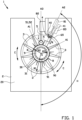
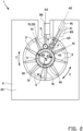
figures 1-4 shows side views of a transfer apparatus with a transfer ring, a first rolling device, a second rolling device, first ring segments and a second ring segment according to a first embodiment of the invention during different steps of a method for transferring one or more plies onto a carcass package on a tire building drum; -
figure 5 shows a side view of an alternative transfer apparatus according to a second embodiment of the invention; -
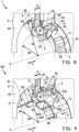
figures 6, 7 and8 show perspective views of the transfer apparatus according tofigures 1 ,3 and4 , respectively; and -
figure 9 shows a perspective view of a further alternative transfer apparatus according to a third embodiment of the invention. -
Figures 1-4 and6-8 show atransfer apparatus 1 according to a first embodiment of the invention. Thetransfer apparatus 1 is used for transferring one or more plies (not shown), in particular one or more breaker plies, onto a carcass package (not shown) on atire building drum 9. - The
tire building drum 9 comprises a number of radiallyexpandable drum segments 90 to shape a carcass (not shown) in a manner known per se. Thetire building drum 9 comprises a plurality of magnets distributed over thedrum segments 90. The plurality of magnets comprises one ormore tip magnets 91 for holding the leading tip or end and/or the trailing tip or end of the one more plies. The magnets may be of different type, size or strength. Alternatively, all of the magnets may be the same type, size and/or strength, but the number of magnets may be varied per drum segment. Typically, thetip magnets 91 generate the largest or strongest magnetic field. - As shown in
figures 1 and6 , thetransfer apparatus 1 comprises atransfer ring 2 for holding the one or more plies during the transfer towards and/or onto the carcass package on thetire building drum 9. Thetransfer ring 2 comprises a plurality offirst ring segments 3 and aframe 20 that extends in a circumferential direction C about a central axis S for holding the plurality offirst ring segments 3. Theframe 20 is arranged for holding eachfirst ring segment 3 of the plurality offirst ring segments 3 in a respective first angular positions A1. The first angular positions A1 of the plurality offirst ring segments 3 are distributed in the circumferential direction C along theframe 20. In the context of the present invention, the 'angular position' is to be interpreted as: the orientation of an object, in this case thefirst ring segment 3, with respect to a reference position as expressed by the amount of rotation necessary to change from one orientation to the other about the central axis S. The first angular positions A1 may for example be expressed in degrees or radians relative to a zero position (typically the top of the transfer ring 2). In this exemplary embodiment, the first angular positions A1 are evenly spaced apart over approximately forty degrees. - Note that for the purpose of holding the
first ring segments 3, theframe 20 itself does not have to be circular. In this exemplary embodiment, the inner contour of theframe 20 is circular, while the outer contour can have any suitable shape depending on the configuration of thetransfer apparatus 1. Theframe 20 may for example hold one or more drives for controlling the operation and/or movement of thetransfer apparatus 1. Moreover, theframe 20 may be interrupted in the circumferential direction C, for example as shown at the top. Hence, theframe 20 does not necessarily form a closed annulus. - Each
first ring segment 3 of the plurality offirst ring segments 3 comprises agripper head 30 and anarm 31 that connects saidgripper head 30 to a radial drive (not shown) for the respectivefirst ring segment 3 in theframe 20. - As shown when comparing
figures 1 and3 orfigures 6 and8 , the plurality offirst ring segments 3 are movable relative to theframe 20 in a radial direction R perpendicular to the central axis S from a first radial distance R1 (figure 3 ) to or up to a second radial distance R2 (figure 1 ) from the central axis S that is smaller than the first radial distance R1. In other words, the plurality offirst ring segments 3 are in an extended state towards the central axis S infigure 1 and in a contracted stated away from the central axis S infigure 3 . The second radial distance R2 may be chosen to substantially match the diameter of the one or more plies to be transferred. Hence, in at the second radial distance R2, the gripper heads 30 of the plurality offirst ring segments 3 are arranged to abut and/or contact the one or more plies. Thefirst ring segments 3 may be provided with one or more retaining elements (not shown) for retaining the one or more plies to the respectivefirst ring segment 3. Thegripper heads 30 may for example be provided with one or more magnets, vacuum openings and/or needles to engage the one or more plies. - The plurality of
first ring segments 3 are preferably fixed against rotation relative to theframe 20. More in particular, thefirst ring segments 3 do not act like rotating bodies, such as rollers. In other words, the plurality offirst ring segments 3 can be moved into abutment or contact with the one or more plies and can subsequently be held stationary or substantially stationary relative to theframe 20 during the transfer to reliably hold said one more plies. - As shown in
figures 1 and6 , thetransfer apparatus 1 further comprises a firstrolling device 4 that is positionable in a second angular position A2 and a secondrolling device 5 that is positionable in a third angular position A3. In this exemplary embodiment, the second angular position A2 and the third angular position A3 are located at or near the top of theframe 20. The second angular position A2 and the third angular position A3 may also be in an alternative location, i.e. at or near one of the sides or even at the bottom of theframe 20. The second angular position A2 and the third angular position A3 are interposed or placed between the plurality of first angular positions A1 in the circumferential direction C. In particular, the second angular position A2 and the third angular position A3 are located in the circumferential direction C between two consecutive first angular positions A1. In the example as shown, the second angular position A2 and the third angular position A3 are located close to each other, i.e. as a group between two consecutive first angular positions A1. Alternatively, the second angular position A2 and the third angular position A3 may be separated and/or between different pairs of consecutive first angular positions A1. - The second angular position A2 is located off-center between two consecutive first angular positions A1 of the plurality of first angular positions A1 in the circumferential direction C to prevent harmonic effects in the one or more plies during the transfer.
- Preferably, the rolling
devices tire building drum 9. In this example, both rollingdevices first rolling device 4 comprises acenter roller 40 for pressing, stitching and/or splicing a central area of the one or more plies onto a carcass (not shown) at thetire building drum 1 in a manner known per se. Thecenter roller 40 is rotatable about a roller axis parallel to the axial direction X. Thefirst rolling device 4 further comprises anarm 41 for holding thecenter roller 40 relative to theframe 20. As best seen infigure 6 , thesecond rolling device 5 comprises twoshoulder roller tire building drum 1 in a manner known per se. Theshoulder rollers - As shown in
figures 3 and7 , thefirst rolling device 4 and/or thesecond rolling device 5 are positionable at the second radial distance R2 from the central axis S to optionally contribute to holding the one or more plies during the transfer. In this exemplary embodiment, as shown infigure 1 , thetransfer apparatus 1 comprises afirst roller drive 81 and asecond roller drive 82 for driving thefirst rolling device 4 and thesecond rolling device 5, respectively. Thefirst rolling device 4 and/or thesecond rolling device 5 are movable in the radial direction R towards the second radial distance R2 and beyond. More in particular, thefirst rolling device 4 and/or thesecond rolling device 5 are movable to or up to a third radial distance R3 smaller than the second radial distance R2. At said third radial distance R3, thefirst rolling device 4 and/or thesecond rolling device 5 are located radially inwards of thefirst ring segments 3, at or near thetire building drum 9 for pressing, stitching and/or splicing the one or more plies against a carcass (not shown) at saidtire building drum 9. - Note that the
first ring segments 3 are absent at the location of thefirst rolling device 4 and thesecond rolling device 5 at the second angular position A2 and the third angular position A3, respectively. There is simply no space to accommodate the conventionalfirst ring segments 3 at the respective angular positions A2, A3. Hence, at least locally at the second angular position A2 and/or the third angular position A3, the one or more plies can not be held by the plurality offirst ring segments 3. This may lead to deformation of the one or more plies. The present invention aims to solve this problem as elucidated below. - As shown in
figures 1 and6 thetransfer apparatus 1 further comprises asecond ring segment 6 that is positionable in the second angular position A2, hence in the same angular position as thefirst rolling device 4. In particular, thesecond ring segment 6 is positionable at the second radial distance R2 from the central axis S. As such, thesecond ring segment 6 can contribute to the holding of the one or more plies during the transfer at a position where the plurality offirst ring segments 3 are unable to do so. Thesecond ring segment 6 may be provided with one or more retaining elements (not shown) for retaining the one or more plies to thesecond ring segment 6. Thesecond ring segment 6 may for example be provided with one or more magnets, vacuum openings and/or needles to engage the one or more plies. - As shown when comparing
figures 1 and4 orfigures 6 and8 , thesecond ring segment 6 is movable in the radial direction R from the second radial distance R2 towards the first radial distance R1 and vice versa. More in particular, thefirst rolling device 4 and thesecond ring segment 6 are both movable in said radial direction R. In this exemplary embodiment, thefirst rolling device 4 and thesecond ring segment 6 are coaxially movable in the radial direction R. In other words, thefirst rolling device 4 and thesecond ring segment 6 are movable along the same axis, being the axis that is aligned with or collinear with the second angular position A2. - The
second ring segment 6 may be arranged to move together withfirst ring segments 3 from the first radial distance R1 to the second radial distance R2. In other words, thetransfer apparatus 1 may be provided with a control unit (not shown) that controls the drives of thefirst ring segments 3 and the secondring segment drive 6 to move thecorresponding ring segments - As schematically shown in
figure 1 , thetransfer apparatus 1 comprises a second ring segment drive 83 that is located to the side of thefirst roller drive 81 and/or thearm 41 of thefirst rolling device 4 so that it does not interfere with the operation of thefirst roller drive 81 nor with the movement of thefirst rolling device 4. Hence, thefirst rolling device 4 and thesecond ring segment 83 can be operated, controlled and/or moved independently. - As shown in
figures 3 and7 , thesecond ring segment 6 is adapted, configured, shaped and/or dimensioned to accommodate thefirst rolling device 4 when thesecond ring segment 6 and thefirst rolling device 4 are in the second angular position A2 at the second radial distance R2 simultaneously. In particular, thesecond ring segment 6 allows for passage of at least a part of thefirst rolling device 4 through thesecond ring segment 6. In particular, thesecond ring segment 6 allows for passage of the entirefirst rolling device 4 beyond or through saidsecond ring segment 6. Thefirst rolling device 4 may thus be moved through or protrude beyond thesecond ring segment 6 partially or completely, to the third radial distance R3 from the central axis S, as shown infigure 4 . Thesecond ring segment 6 may also be retracted from the second radial distance R2 towards the first radial distance R1 while passing along thefirst rolling device 4 as it remains in place at the second radial distance R2, as shown by way of example infigures 4 and8 . - As best seen in
figure 6 , thesecond ring segment 6 comprises afirst leg 61 extending at a first side of thefirst rolling device 4 in the circumferential direction C and asecond leg 61 extending at a second side of thefirst rolling device 4 in the circumferential direction C opposite to the first side. The twolegs first rolling device 4 in the circumferential direction C without interfering with the operation of said first rollingdevice 4. Preferably, thelegs first ring segments 3. In particular, thelegs first ring segments 3 are slightly concave compared to the second radial distance R2 and thus also contact the one or more plies along two linearly extending, parallel contact surfaces. - The one or more retaining elements of the second ring segment may be provided in or at the
legs - The
second ring segment 6 further comprises a first connectingmember 63 and a second connectingmember 64 interconnecting thefirst leg 61 and thesecond leg 62 at a third side of thefirst rolling device 4 in the axial direction X parallel to the central axis S and at a fourth side of thefirst rolling device 4 in the axial direction X opposite to the third side, respectively. By interconnecting thefirst leg 61 and thesecond leg 62, thelegs second ring segment 6 can be positioned more accurately relative to each other. In other words, thesecond ring segment 6 can be more rigid. In addition, thefirst leg 61, thesecond leg 62, the first connectingmember 63 and the second connectingmember 64 can form a shell around the first side, the second side, the third side and the fourth side of thefirst rolling device 4 when thesecond ring segment 6 and thefirst rolling device 4 are at the second radial distance R2 simultaneously. In other words, thesecond ring segment 6 is hollow to accommodate thefirst rolling device 4 at least partially inside its outer boundaries. - As best seen in
figure 1 , thesecond ring segment 6 further comprises anarm 65 that extends along one of the sides of thefirst rolling device 4 in the circumferential direction C for holding thesecond ring segment 6 relative to theframe 20. In particular, thearm 65 of thesecond ring segment 6 operationally connects thesecond ring segment 6 to the corresponding secondring segment drive 83. Thearm 65 is located to the side of thefirst rolling device 4 so that it does not interfere with the movement of said first rollingdevice 4 in the radial direction R. It is noted that thearm 65 of thesecond ring segment 6 may alternatively be placed at a side of thefirst rolling device 4 in the axial direction X parallel to the central axis S. - The
second ring segment 6 may be retrofitted to an existing transfer apparatus, in which case all of the aforementioned features of thesecond ring segment 6 are to be interpreted as suitable for use in an existing transfer apparatus in combination with the first rolling device of said existing transfer apparatus. -
Figure 5 shows analternative transfer apparatus 101 according to a second embodiment of the invention, which differs from the previously discussedtransfer apparatus 1 in that it comprises athird ring segment 7 that is positionable in the third angular position A3 at the second radial distance R2 from the central axis S. Thethird ring segment 7 may have the same features as the aforementionedsecond ring segment 6, only now adapted, configured, shaped and/or dimensioned to partially or completely accommodate thesecond rolling device 5. Thethird ring segment 7 can thus be used to provide additional support to the one or more plies at the location of the third angular position A3. For this purpose, thealternative transfer apparatus 101 comprises a third ring segment drive 84 to drive thethird ring segment 7 in the radial direction R from the second radial distance R2 towards the first radial distance R1 and vice versa. -
Figure 9 shows a furtheralternative transfer apparatus 201 according to a third embodiment of the invention, which differs from the previously discussedtransfer apparatuss second ring segment 206 comprises afirst leg 261 extending at a first side of thefirst rolling device 4 in the axial direction X parallel to the central axis S and asecond leg 62 extending at a second side of thefirst rolling device 4 in the axial direction X opposite to the first side. The twolegs first rolling device 4 in the axial direction X parallel to the central axis S without interfering with the operation of said first rollingdevice 4. Thesecond ring segment 206 may again be provided with one or more retaining elements, which in this case may be provided in thelegs legs figure 6 , thelegs figure 9 are interconnected by interconnectingmembers first rolling device 4 in the circumferential direction C and along a fourth side of thefirst rolling device 4 opposite to the third side in said circumferential direction C, respectively. In the context of most of the claims, the second ring segment may either be thesecond ring segment 6 as shown infigures 1-4 and6-8 or thethird ring segment 7 as shown infigure 5 . Moreover, it is pointed out that the claims do not exclude the possibility of providing both thesecond ring segment 6 as shown infigures 1-4 and6-8 and thethird ring segment 7 as shown infigure 5 in thesame transfer apparatus first rolling device 4 and thesecond rolling device 5 are in separate, spaced apart angular positions A2, A3. - A method for transferring one or more plies, in particular breaker plies, onto the carcass package on the
tire building drum 9 will now be briefly elucidated below with reference tofigures 1-4 and6-8 . -
Figures 1 and6 show the situation in which thesecond ring segment 6 is positioned and/or moved in the radial direction R in the second angular position A2 at the second radial distance R2 from the central axis S. As discussed before, thesecond ring segment 6 can be moved together, i.e. simultaneously, withfirst ring segments 3 from the first radial distance R1 to the second radial distance R2. Infigures 1 and6 , thefirst rolling device 4 remains retracted towards, at or near the first radial distance R1. It is noted that, alternatively, thefirst rolling device 4 may be moved towards or to the second radial distance R2 already prior to or simultaneously with the step of positioning thesecond ring segment 6 in the second angular position A2 at the second radial distance R2. In that case, thesecond ring segment 6 would accommodate or move into a position for accommodating thefirst rolling device 4 at the second radial distance R2. - In this example, the
first rolling device 4 is moved towards the second radial distance R2 only after thesecond ring segment 6 is at the second radial distance R2, as shown infigure 2 . Note that thefirst rolling device 4 may be stopped just short of the second radial distance R2 to prevent that thefirst rolling device 4 unintentionally contacts the one or more plies. In particular, thefirst rolling device 4 may be positioned inside thesecond ring segment 6, with thelegs second ring segment 6 protruding beyond thefirst rolling device 4 in the radial direction R to the second radial distance R2. -
Figures 3 and7 show the situation in which thefirst rolling device 4 and thesecond ring segment 6 are both moved to or at the second radial distance R2 from the central axis S. -
Figures 4 and8 show the situation in which thefirst rolling device 4 has been moved through thesecond ring segment 6 towards or to the third radial distance R3 from the central axis S. In this case, thesecond ring segment 6 is retracted from the second radial distance R2 towards or to the first radial distance R1, thereby passing along or over thefirst rolling device 4. In other words, thefirst rolling device 4 has passed entirely through thesecond ring segment 6. Alternatively, thesecond ring segment 6 may remain in place at the second radial distance R2, in which case the first rolling device would only extend partially through thesecond ring segment 6 to contact the one or more plies at the third radial distance R3. - It will be appreciated by one skilled in the art that the aforementioned steps of the method apply mutatis mutandis to the
third ring segment 7 offigure 5 . - Optionally, the method comprises the step of positioning the two
shoulder wheels figure 6 , in the third angular position A3 at the second radial distance R2 and moving or spacing them apart at in the axial direction X parallel to the central axis S to a width W that matches or substantially matches a width of the one or more plies in said axial direction X. In this way, the twoshoulder wheels second ring segment 6 or thethird ring segment 7. - As a further option, the method may comprise the step of providing the
tire building drum 9 concentrically within thetransfer ring 1, i.e. with its rotation axis collinear to the central axis S of thetransfer apparatus 1, and rotating thetire building drum 9 about the central axis S into a transfer position, as shown infigure 1 . In said transfer position, the one ormore tip magnets 91 are offset in the circumferential direction C from the second angular position A2 over an offset angle H in the range of ninety degrees to one-hundred-and-eighty degrees, and preferably in the range of one-hundred-and-forty degrees to one-hundred-and-eighty degrees. Thetip magnets 91 are typically the magnets on thetire building drum 9 having the strongest magnetic field. By offsetting the one ormore tip magnets 91, the influence of this strong magnetic field on the position of the one or more plies at the second angular position A2 can be reduced and/or minimized. It is noted that this principle may also be applied independently from the present invention, i.e. without the use of thesecond ring segment 6 or thethird ring segment 7. - It is to be understood that the above description is included to illustrate the operation of the preferred embodiments and is not meant to limit the scope of the invention. From the above discussion, many variations will be apparent to one skilled in the art that would yet be encompassed by the scope of the present invention.
-
- 1
- transfer apparatus
- 2
- transfer ring
- 20
- frame
- 3
- first ring segment
- 30
- gripper head
- 31
- arm
- 4
- first rolling device
- 40
- center roller
- 41
- arm
- 5
- second rolling device
- 51
- shoulder roller
- 52
- shoulder roller
- 6
- second ring segment
- 61
- first leg
- 62
- second leg
- 63
- first connecting member
- 64
- second connecting member
- 65
- arm
- 7
- third ring segment
- 81
- first roller drive
- 82
- second roller drive
- 83
- second ring segment drive
- 84
- third ring segment drive
- 9
- tire building drum
- 90
- drum segment
- 91
- tip magnet
- 101
- alternative transfer apparatus
- 201
- further alternative transfer apparatus
- 206
- second ring segment
- 261
- first leg
- 262
- second leg
- 263
- first interconnecting member
- 264
- second interconnecting member
- A1
- first angular position
- A2
- second angular position
- A3
- third angular position
- C
- circumferential direction
- H
- offset angle
- R
- radial direction
- R1
- first radial distance
- R2
- second radial distance
- R3
- third radial distance
- S
- central axis
- W
- width
- X
- axial direction
Claims (2)
- Method for transferring one or more plies onto a carcass package on a tire building drum using a transfer apparatus, wherein the transfer apparatus comprises a transfer ring with a plurality of first ring segments and a frame that extends in a circumferential direction about a central axis for holding the plurality of first ring segments distributed in the circumferential direction along the frame, wherein the plurality of first ring segments are movable relative to the frame in a radial direction perpendicular to the central axis from a first radial distance to a second radial distance from the central axis that is smaller than the first radial distance, wherein the transfer apparatus further comprises two shoulder wheels in an angular position interposed between the plurality of first ring segments in the circumferential direction for stitching the one or more plies to the carcass package on the tire building drum, wherein the two shoulder wheels, at the second radial distance, are movable apart in an axial direction parallel to the central axis to a variable width to match a width of the one or more plies in said axial direction, wherein the method comprises the steps of:- transferring one or more plies onto a carcass package on a tire building drum using the transfer apparatus; and- at the second radial distance, moving the two shoulder wheels apart in an axial direction parallel to the central axis to match a width of the one or more plies in said axial direction, wherein the two shoulder wheels are at the second radial distance during the transfer to provide additional support to the one or more plies during the transfer at the longitudinal edges of said one or more plies.
- Method according to claim 1, wherein the transfer apparatus comprises a further ring segment, wherein the method comprises the step of positioning the further ring segment in the angular position of the two shoulder wheels at the second radial distance from the central axis.
Applications Claiming Priority (3)
| Application Number | Priority Date | Filing Date | Title |
|---|---|---|---|
| NL2022628A NL2022628B1 (en) | 2019-02-22 | 2019-02-22 | Transfer apparatus and method for transferring one or more plies onto a carcass package on a tire building drum |
| EP20702934.9A EP3829856B1 (en) | 2019-02-22 | 2020-01-27 | Transfer apparatus and method for transferring one or more plies onto a carcass package on a tire building drum |
| PCT/NL2020/050039 WO2020171694A1 (en) | 2019-02-22 | 2020-01-27 | Transfer apparatus and method for transferring one or more plies onto a carcass package on a tire building drum |
Related Parent Applications (1)
| Application Number | Title | Priority Date | Filing Date |
|---|---|---|---|
| EP20702934.9A Division EP3829856B1 (en) | 2019-02-22 | 2020-01-27 | Transfer apparatus and method for transferring one or more plies onto a carcass package on a tire building drum |
Publications (4)
| Publication Number | Publication Date |
|---|---|
| EP4282636A2 true EP4282636A2 (en) | 2023-11-29 |
| EP4282636A3 EP4282636A3 (en) | 2024-02-21 |
| EP4282636B1 EP4282636B1 (en) | 2025-09-24 |
| EP4282636C0 EP4282636C0 (en) | 2025-09-24 |
Family
ID=66218371
Family Applications (2)
| Application Number | Title | Priority Date | Filing Date |
|---|---|---|---|
| EP23202497.6A Active EP4282636B1 (en) | 2019-02-22 | 2020-01-27 | Method for transferring one or more plies onto a carcass package on a tire building drum |
| EP20702934.9A Active EP3829856B1 (en) | 2019-02-22 | 2020-01-27 | Transfer apparatus and method for transferring one or more plies onto a carcass package on a tire building drum |
Family Applications After (1)
| Application Number | Title | Priority Date | Filing Date |
|---|---|---|---|
| EP20702934.9A Active EP3829856B1 (en) | 2019-02-22 | 2020-01-27 | Transfer apparatus and method for transferring one or more plies onto a carcass package on a tire building drum |
Country Status (13)
| Country | Link |
|---|---|
| US (2) | US11390048B2 (en) |
| EP (2) | EP4282636B1 (en) |
| JP (1) | JP7089640B2 (en) |
| KR (1) | KR102251591B1 (en) |
| CN (4) | CN115447185B (en) |
| ES (1) | ES2963104T3 (en) |
| HU (1) | HUE064912T2 (en) |
| MX (1) | MX2021002828A (en) |
| NL (1) | NL2022628B1 (en) |
| PL (1) | PL3829856T3 (en) |
| RS (1) | RS64966B1 (en) |
| TW (1) | TW202103905A (en) |
| WO (1) | WO2020171694A1 (en) |
Families Citing this family (3)
| Publication number | Priority date | Publication date | Assignee | Title |
|---|---|---|---|---|
| NL2022628B1 (en) * | 2019-02-22 | 2020-08-31 | Vmi Holland Bv | Transfer apparatus and method for transferring one or more plies onto a carcass package on a tire building drum |
| NL2026457B1 (en) * | 2020-09-11 | 2022-05-12 | Vmi Holland Bv | Belt and tread drum, assembly and method for manufacturing a belt and tread package |
| JP2024043078A (en) * | 2022-09-16 | 2024-03-29 | Toyo Tire株式会社 | Green tire manufacturing method and green tire manufacturing device |
Family Cites Families (20)
| Publication number | Priority date | Publication date | Assignee | Title |
|---|---|---|---|---|
| JPS5149283B1 (en) | 1971-06-15 | 1976-12-25 | ||
| JPS5149283A (en) * | 1974-10-25 | 1976-04-28 | Bridgestone Tire Co Ltd | Namataiyaseikeihoho oyobi sonosochi |
| US4634489A (en) * | 1984-07-18 | 1987-01-06 | The Goodyear Tire & Rubber Company | Device for transferring a tire carcass band |
| NL8503208A (en) | 1985-11-21 | 1987-06-16 | Vmi Epe Holland | APPARATUS FOR FITTING AND ROLLING THE TREADMILL AND THE BELT ON THE CARCASE IN THE MANUFACTURE OF AN AIR TIRE. |
| ES2044079T3 (en) * | 1988-01-25 | 1994-01-01 | Bridgestone Corp | CYLINDRICAL MEMBERS TRANSPORTATION DEVICE AND TIRES MANUFACTURING MACHINE. |
| NL1002306C2 (en) * | 1996-02-12 | 1997-08-13 | Vmi Epe Holland | Assembly of devices for building a green tire for vehicles. |
| DE19942220A1 (en) | 1999-09-03 | 2001-03-08 | Thyssenkrupp Ind Ag | Tire building drum with pressure units |
| US6364981B1 (en) | 1999-12-14 | 2002-04-02 | The Goodyear Tire & Rubber Company | Forming and application of tire ply |
| KR100319661B1 (en) | 2000-01-05 | 2002-01-05 | 조충환 | A bead filler fitting machine for a large size tire |
| US8098318B2 (en) | 2007-11-27 | 2012-01-17 | Panasonic Corporation | Video reproduction apparatus, digital camera, semiconductor integrated circuit, and method for video reproduction |
| RU2455164C1 (en) | 2008-04-18 | 2012-07-10 | Пирелли Тайр С.П.А. | Method and device for assembling tires |
| CN102862303B (en) | 2012-09-28 | 2014-12-24 | 天津赛象科技股份有限公司 | Transmission ring with rolling function |
| CN102873896A (en) * | 2012-09-28 | 2013-01-16 | 天津赛象科技股份有限公司 | Efficient triple-drum forming machine |
| KR101595487B1 (en) | 2014-09-25 | 2016-02-18 | 금호타이어 주식회사 | Device of transferring green case for tire builder |
| JP2016074173A (en) | 2014-10-08 | 2016-05-12 | 株式会社ブリヂストン | Carrier device for tire constituting member laminate and molding method for tire constituting member laminate |
| CN104441718B (en) | 2014-11-11 | 2017-11-21 | 萨驰华辰机械(苏州)有限公司 | The integrated rolling station of high efficiency |
| CN207345108U (en) * | 2017-08-31 | 2018-05-11 | 萨驰华辰机械(苏州)有限公司 | A kind of tire unloader |
| SK288891B6 (en) * | 2017-11-07 | 2021-08-25 | Mesnac European Research And Technical Centre S.R.O. | Transportable device of the belt-tread pack in production of radial tyre casing |
| CN109291483B (en) | 2018-09-19 | 2021-03-19 | 淮阴工学院 | A tire building machine |
| NL2022628B1 (en) | 2019-02-22 | 2020-08-31 | Vmi Holland Bv | Transfer apparatus and method for transferring one or more plies onto a carcass package on a tire building drum |
-
2019
- 2019-02-22 NL NL2022628A patent/NL2022628B1/en not_active IP Right Cessation
-
2020
- 2020-01-27 MX MX2021002828A patent/MX2021002828A/en unknown
- 2020-01-27 RS RS20231215A patent/RS64966B1/en unknown
- 2020-01-27 WO PCT/NL2020/050039 patent/WO2020171694A1/en not_active Ceased
- 2020-01-27 KR KR1020207013400A patent/KR102251591B1/en active Active
- 2020-01-27 HU HUE20702934A patent/HUE064912T2/en unknown
- 2020-01-27 EP EP23202497.6A patent/EP4282636B1/en active Active
- 2020-01-27 US US17/281,921 patent/US11390048B2/en active Active
- 2020-01-27 EP EP20702934.9A patent/EP3829856B1/en active Active
- 2020-01-27 JP JP2021517681A patent/JP7089640B2/en active Active
- 2020-01-27 ES ES20702934T patent/ES2963104T3/en active Active
- 2020-01-27 PL PL20702934.9T patent/PL3829856T3/en unknown
- 2020-01-31 TW TW109102998A patent/TW202103905A/en unknown
- 2020-02-18 CN CN202211304788.6A patent/CN115447185B/en active Active
- 2020-02-18 CN CN202010099294.3A patent/CN111605236B/en active Active
- 2020-02-18 CN CN202023180209.0U patent/CN215750896U/en active Active
- 2020-02-18 CN CN202020180226.5U patent/CN212353006U/en active Active
-
2022
- 2022-07-15 US US17/812,986 patent/US11780187B2/en active Active
Also Published As
| Publication number | Publication date |
|---|---|
| KR20200104286A (en) | 2020-09-03 |
| NL2022628B1 (en) | 2020-08-31 |
| EP4282636B1 (en) | 2025-09-24 |
| CN212353006U (en) | 2021-01-15 |
| HUE064912T2 (en) | 2024-04-28 |
| KR102251591B1 (en) | 2021-05-14 |
| TW202103905A (en) | 2021-02-01 |
| BR112021004897A2 (en) | 2021-08-31 |
| CN115447185A (en) | 2022-12-09 |
| CN111605236B (en) | 2022-11-08 |
| EP4282636C0 (en) | 2025-09-24 |
| EP4282636A3 (en) | 2024-02-21 |
| US11390048B2 (en) | 2022-07-19 |
| RS64966B1 (en) | 2024-01-31 |
| US20220347954A1 (en) | 2022-11-03 |
| CN215750896U (en) | 2022-02-08 |
| MX2021002828A (en) | 2021-05-27 |
| US11780187B2 (en) | 2023-10-10 |
| EP3829856A1 (en) | 2021-06-09 |
| PL3829856T3 (en) | 2024-03-11 |
| US20210370627A1 (en) | 2021-12-02 |
| WO2020171694A1 (en) | 2020-08-27 |
| JP2022510544A (en) | 2022-01-27 |
| CN115447185B (en) | 2025-11-21 |
| EP3829856C0 (en) | 2023-10-11 |
| JP7089640B2 (en) | 2022-06-22 |
| EP3829856B1 (en) | 2023-10-11 |
| ES2963104T3 (en) | 2024-03-25 |
| CN111605236A (en) | 2020-09-01 |
Similar Documents
| Publication | Publication Date | Title |
|---|---|---|
| US11780187B2 (en) | Transfer apparatus and method for transferring one or more plies onto a carcass package on a tire building drum | |
| US8939486B2 (en) | Center expanding chuck | |
| RU2288099C2 (en) | Drum for production of the motorcar tires and the device for bending the tire beads upward and the method of production of the green tires | |
| JP4956495B2 (en) | Raw tire forming method and raw tire forming apparatus | |
| TWI787483B (en) | Process and device for the production of tyres | |
| CN111267381B (en) | Tire building drum and method of using same | |
| US20060037708A1 (en) | Method for pressure bonding of a breaker-tread assembly with a carcass assembly by means of stitching in the manufacture of green tyres and device for accomplishment of such method | |
| US3772125A (en) | Tire building drum having a carcass ply support and foldover mechanism | |
| RU2688843C2 (en) | Method and device for wrapping retaining ring structural elements in process of assembling tires for wheels of vehicles | |
| US11318694B2 (en) | Manufacturing method of tire component and manufacturing device of tire component | |
| US9950485B2 (en) | Apparatus and method for forming an annular apex filler for tire beads | |
| EP2763861A1 (en) | Method and apparatus for mounting a tire | |
| BR112021004897B1 (en) | TRANSFER APPARATUS AND METHOD FOR TRANSFERRING ONE OR MORE PLYING TO A CARCASS PACKAGE ON A TIRE FORMING DRUM | |
| NL2011555C2 (en) | Transfer assembly for transferring tire components. | |
| JP2020188214A (en) | Edge face array apparatus | |
| JP2003072991A (en) | Core tube support device |
Legal Events
| Date | Code | Title | Description |
|---|---|---|---|
| PUAI | Public reference made under article 153(3) epc to a published international application that has entered the european phase |
Free format text: ORIGINAL CODE: 0009012 |
|
| STAA | Information on the status of an ep patent application or granted ep patent |
Free format text: STATUS: THE APPLICATION HAS BEEN PUBLISHED |
|
| AC | Divisional application: reference to earlier application |
Ref document number: 3829856 Country of ref document: EP Kind code of ref document: P |
|
| AK | Designated contracting states |
Kind code of ref document: A2 Designated state(s): AL AT BE BG CH CY CZ DE DK EE ES FI FR GB GR HR HU IE IS IT LI LT LU LV MC MK MT NL NO PL PT RO RS SE SI SK SM TR |
|
| REG | Reference to a national code |
Ref country code: DE Ref legal event code: R079 Free format text: PREVIOUS MAIN CLASS: B29D0030280000 Ipc: B29D0030260000 Ref country code: DE Ref legal event code: R079 Ref document number: 602020059570 Country of ref document: DE Free format text: PREVIOUS MAIN CLASS: B29D0030280000 Ipc: B29D0030260000 |
|
| PUAL | Search report despatched |
Free format text: ORIGINAL CODE: 0009013 |
|
| AK | Designated contracting states |
Kind code of ref document: A3 Designated state(s): AL AT BE BG CH CY CZ DE DK EE ES FI FR GB GR HR HU IE IS IT LI LT LU LV MC MK MT NL NO PL PT RO RS SE SI SK SM TR |
|
| RIC1 | Information provided on ipc code assigned before grant |
Ipc: B29D 30/28 20060101ALI20240116BHEP Ipc: B29D 30/26 20060101AFI20240116BHEP |
|
| STAA | Information on the status of an ep patent application or granted ep patent |
Free format text: STATUS: REQUEST FOR EXAMINATION WAS MADE |
|
| 17P | Request for examination filed |
Effective date: 20240227 |
|
| RBV | Designated contracting states (corrected) |
Designated state(s): AL AT BE BG CH CY CZ DE DK EE ES FI FR GB GR HR HU IE IS IT LI LT LU LV MC MK MT NL NO PL PT RO RS SE SI SK SM TR |
|
| GRAP | Despatch of communication of intention to grant a patent |
Free format text: ORIGINAL CODE: EPIDOSNIGR1 |
|
| STAA | Information on the status of an ep patent application or granted ep patent |
Free format text: STATUS: GRANT OF PATENT IS INTENDED |
|
| INTG | Intention to grant announced |
Effective date: 20250620 |
|
| GRAS | Grant fee paid |
Free format text: ORIGINAL CODE: EPIDOSNIGR3 |
|
| GRAA | (expected) grant |
Free format text: ORIGINAL CODE: 0009210 |
|
| STAA | Information on the status of an ep patent application or granted ep patent |
Free format text: STATUS: THE PATENT HAS BEEN GRANTED |
|
| AC | Divisional application: reference to earlier application |
Ref document number: 3829856 Country of ref document: EP Kind code of ref document: P |
|
| AK | Designated contracting states |
Kind code of ref document: B1 Designated state(s): AL AT BE BG CH CY CZ DE DK EE ES FI FR GB GR HR HU IE IS IT LI LT LU LV MC MK MT NL NO PL PT RO RS SE SI SK SM TR |
|
| REG | Reference to a national code |
Ref country code: GB Ref legal event code: FG4D |
|
| REG | Reference to a national code |
Ref country code: CH Ref legal event code: EP |
|
| REG | Reference to a national code |
Ref country code: IE Ref legal event code: FG4D |
|
| U01 | Request for unitary effect filed |
Effective date: 20250926 |
|
| U07 | Unitary effect registered |
Designated state(s): AT BE BG DE DK EE FI FR IT LT LU LV MT NL PT RO SE SI Effective date: 20251008 |
|
| PG25 | Lapsed in a contracting state [announced via postgrant information from national office to epo] |
Ref country code: NO Free format text: LAPSE BECAUSE OF FAILURE TO SUBMIT A TRANSLATION OF THE DESCRIPTION OR TO PAY THE FEE WITHIN THE PRESCRIBED TIME-LIMIT Effective date: 20251224 |
|
| PG25 | Lapsed in a contracting state [announced via postgrant information from national office to epo] |
Ref country code: HR Free format text: LAPSE BECAUSE OF FAILURE TO SUBMIT A TRANSLATION OF THE DESCRIPTION OR TO PAY THE FEE WITHIN THE PRESCRIBED TIME-LIMIT Effective date: 20250924 |
|
| PG25 | Lapsed in a contracting state [announced via postgrant information from national office to epo] |
Ref country code: GR Free format text: LAPSE BECAUSE OF FAILURE TO SUBMIT A TRANSLATION OF THE DESCRIPTION OR TO PAY THE FEE WITHIN THE PRESCRIBED TIME-LIMIT Effective date: 20251225 |
|
| PG25 | Lapsed in a contracting state [announced via postgrant information from national office to epo] |
Ref country code: RS Free format text: LAPSE BECAUSE OF FAILURE TO SUBMIT A TRANSLATION OF THE DESCRIPTION OR TO PAY THE FEE WITHIN THE PRESCRIBED TIME-LIMIT Effective date: 20251224 |
|
| U20 | Renewal fee for the european patent with unitary effect paid |
Year of fee payment: 7 Effective date: 20260129 |
|
| PG25 | Lapsed in a contracting state [announced via postgrant information from national office to epo] |
Ref country code: SM Free format text: LAPSE BECAUSE OF FAILURE TO SUBMIT A TRANSLATION OF THE DESCRIPTION OR TO PAY THE FEE WITHIN THE PRESCRIBED TIME-LIMIT Effective date: 20250924 |
|
| PG25 | Lapsed in a contracting state [announced via postgrant information from national office to epo] |
Ref country code: ES Free format text: LAPSE BECAUSE OF FAILURE TO SUBMIT A TRANSLATION OF THE DESCRIPTION OR TO PAY THE FEE WITHIN THE PRESCRIBED TIME-LIMIT Effective date: 20250924 |
|
| PG25 | Lapsed in a contracting state [announced via postgrant information from national office to epo] |
Ref country code: IS Free format text: LAPSE BECAUSE OF FAILURE TO SUBMIT A TRANSLATION OF THE DESCRIPTION OR TO PAY THE FEE WITHIN THE PRESCRIBED TIME-LIMIT Effective date: 20260124 |
|
| PG25 | Lapsed in a contracting state [announced via postgrant information from national office to epo] |
Ref country code: CZ Free format text: LAPSE BECAUSE OF FAILURE TO SUBMIT A TRANSLATION OF THE DESCRIPTION OR TO PAY THE FEE WITHIN THE PRESCRIBED TIME-LIMIT Effective date: 20250924 |
|
| PG25 | Lapsed in a contracting state [announced via postgrant information from national office to epo] |
Ref country code: PL Free format text: LAPSE BECAUSE OF FAILURE TO SUBMIT A TRANSLATION OF THE DESCRIPTION OR TO PAY THE FEE WITHIN THE PRESCRIBED TIME-LIMIT Effective date: 20250924 |
|
| PG25 | Lapsed in a contracting state [announced via postgrant information from national office to epo] |
Ref country code: SK Free format text: LAPSE BECAUSE OF FAILURE TO SUBMIT A TRANSLATION OF THE DESCRIPTION OR TO PAY THE FEE WITHIN THE PRESCRIBED TIME-LIMIT Effective date: 20250924 |