EP4282518A1 - Dispositif et procédé de préparation de la pâte de ciment osseux - Google Patents
Dispositif et procédé de préparation de la pâte de ciment osseux Download PDFInfo
- Publication number
- EP4282518A1 EP4282518A1 EP22174728.0A EP22174728A EP4282518A1 EP 4282518 A1 EP4282518 A1 EP 4282518A1 EP 22174728 A EP22174728 A EP 22174728A EP 4282518 A1 EP4282518 A1 EP 4282518A1
- Authority
- EP
- European Patent Office
- Prior art keywords
- ampoule
- cartridge
- interior
- reservoir
- connection
- Prior art date
- Legal status (The legal status is an assumption and is not a legal conclusion. Google has not performed a legal analysis and makes no representation as to the accuracy of the status listed.)
- Granted
Links
- 239000002639 bone cement Substances 0.000 title claims abstract description 133
- 238000004519 manufacturing process Methods 0.000 title description 5
- 239000000178 monomer Substances 0.000 claims abstract description 93
- 239000007788 liquid Substances 0.000 claims abstract description 90
- 239000000843 powder Substances 0.000 claims abstract description 49
- 239000003708 ampul Substances 0.000 claims description 161
- 238000000034 method Methods 0.000 claims description 14
- 239000000654 additive Substances 0.000 description 14
- 229920003229 poly(methyl methacrylate) Polymers 0.000 description 14
- 239000004926 polymethyl methacrylate Substances 0.000 description 14
- 230000000996 additive effect Effects 0.000 description 12
- 239000003242 anti bacterial agent Substances 0.000 description 7
- 230000005484 gravity Effects 0.000 description 7
- 229920000642 polymer Polymers 0.000 description 7
- 241001295925 Gegenes Species 0.000 description 6
- 229940088710 antibiotic agent Drugs 0.000 description 6
- VVQNEPGJFQJSBK-UHFFFAOYSA-N Methyl methacrylate Chemical compound COC(=O)C(C)=C VVQNEPGJFQJSBK-UHFFFAOYSA-N 0.000 description 5
- 239000012634 fragment Substances 0.000 description 5
- 239000003999 initiator Substances 0.000 description 5
- 239000000463 material Substances 0.000 description 5
- 210000003739 neck Anatomy 0.000 description 5
- VYPSYNLAJGMNEJ-UHFFFAOYSA-N Silicium dioxide Chemical compound O=[Si]=O VYPSYNLAJGMNEJ-UHFFFAOYSA-N 0.000 description 4
- 238000007599 discharging Methods 0.000 description 4
- 239000013543 active substance Substances 0.000 description 3
- 239000012530 fluid Substances 0.000 description 3
- 239000000203 mixture Substances 0.000 description 3
- 239000002245 particle Substances 0.000 description 3
- 238000006116 polymerization reaction Methods 0.000 description 3
- -1 polypropylene Polymers 0.000 description 3
- 239000000126 substance Substances 0.000 description 3
- 230000001960 triggered effect Effects 0.000 description 3
- OMPJBNCRMGITSC-UHFFFAOYSA-N Benzoylperoxide Chemical compound C=1C=CC=CC=1C(=O)OOC(=O)C1=CC=CC=C1 OMPJBNCRMGITSC-UHFFFAOYSA-N 0.000 description 2
- VTYYLEPIZMXCLO-UHFFFAOYSA-L Calcium carbonate Chemical compound [Ca+2].[O-]C([O-])=O VTYYLEPIZMXCLO-UHFFFAOYSA-L 0.000 description 2
- BAPJBEWLBFYGME-UHFFFAOYSA-N Methyl acrylate Chemical compound COC(=O)C=C BAPJBEWLBFYGME-UHFFFAOYSA-N 0.000 description 2
- PPBRXRYQALVLMV-UHFFFAOYSA-N Styrene Chemical compound C=CC1=CC=CC=C1 PPBRXRYQALVLMV-UHFFFAOYSA-N 0.000 description 2
- GWEVSGVZZGPLCZ-UHFFFAOYSA-N Titan oxide Chemical compound O=[Ti]=O GWEVSGVZZGPLCZ-UHFFFAOYSA-N 0.000 description 2
- MCMNRKCIXSYSNV-UHFFFAOYSA-N Zirconium dioxide Chemical compound O=[Zr]=O MCMNRKCIXSYSNV-UHFFFAOYSA-N 0.000 description 2
- TZCXTZWJZNENPQ-UHFFFAOYSA-L barium sulfate Chemical compound [Ba+2].[O-]S([O-])(=O)=O TZCXTZWJZNENPQ-UHFFFAOYSA-L 0.000 description 2
- 235000019400 benzoyl peroxide Nutrition 0.000 description 2
- 210000000988 bone and bone Anatomy 0.000 description 2
- 239000001913 cellulose Substances 0.000 description 2
- 229920002678 cellulose Polymers 0.000 description 2
- 230000001066 destructive effect Effects 0.000 description 2
- 230000001627 detrimental effect Effects 0.000 description 2
- 239000007789 gas Substances 0.000 description 2
- 239000011521 glass Substances 0.000 description 2
- 125000002887 hydroxy group Chemical group [H]O* 0.000 description 2
- GYVGXEWAOAAJEU-UHFFFAOYSA-N n,n,4-trimethylaniline Chemical compound CN(C)C1=CC=C(C)C=C1 GYVGXEWAOAAJEU-UHFFFAOYSA-N 0.000 description 2
- 229920003023 plastic Polymers 0.000 description 2
- 239000004033 plastic Substances 0.000 description 2
- 230000000717 retained effect Effects 0.000 description 2
- 230000002441 reversible effect Effects 0.000 description 2
- 238000000926 separation method Methods 0.000 description 2
- 239000000377 silicon dioxide Substances 0.000 description 2
- 235000012239 silicon dioxide Nutrition 0.000 description 2
- 230000007704 transition Effects 0.000 description 2
- GNFTZDOKVXKIBK-UHFFFAOYSA-N 3-(2-methoxyethoxy)benzohydrazide Chemical compound COCCOC1=CC=CC(C(=O)NN)=C1 GNFTZDOKVXKIBK-UHFFFAOYSA-N 0.000 description 1
- 208000031872 Body Remains Diseases 0.000 description 1
- FGUUSXIOTUKUDN-IBGZPJMESA-N C1(=CC=CC=C1)N1C2=C(NC([C@H](C1)NC=1OC(=NN=1)C1=CC=CC=C1)=O)C=CC=C2 Chemical compound C1(=CC=CC=C1)N1C2=C(NC([C@H](C1)NC=1OC(=NN=1)C1=CC=CC=C1)=O)C=CC=C2 FGUUSXIOTUKUDN-IBGZPJMESA-N 0.000 description 1
- CEAZRRDELHUEMR-URQXQFDESA-N Gentamicin Chemical compound O1[C@H](C(C)NC)CC[C@@H](N)[C@H]1O[C@H]1[C@H](O)[C@@H](O[C@@H]2[C@@H]([C@@H](NC)[C@@](C)(O)CO2)O)[C@H](N)C[C@@H]1N CEAZRRDELHUEMR-URQXQFDESA-N 0.000 description 1
- 229930182566 Gentamicin Natural products 0.000 description 1
- 239000004698 Polyethylene Substances 0.000 description 1
- 239000004743 Polypropylene Substances 0.000 description 1
- 229920002472 Starch Polymers 0.000 description 1
- 238000010521 absorption reaction Methods 0.000 description 1
- 239000012190 activator Substances 0.000 description 1
- 230000003115 biocidal effect Effects 0.000 description 1
- 229910000019 calcium carbonate Inorganic materials 0.000 description 1
- MYPYJXKWCTUITO-KIIOPKALSA-N chembl3301825 Chemical compound O([C@@H]1[C@@H](O)[C@H](O)[C@@H](CO)O[C@H]1OC1=C2C=C3C=C1OC1=CC=C(C=C1Cl)[C@@H](O)[C@H](C(N[C@@H](CC(N)=O)C(=O)N[C@H]3C(=O)N[C@H]1C(=O)N[C@H](C(N[C@H](C3=CC(O)=CC(O)=C3C=3C(O)=CC=C1C=3)C(O)=O)=O)[C@H](O)C1=CC=C(C(=C1)Cl)O2)=O)NC(=O)[C@@H](CC(C)C)NC)[C@H]1C[C@](C)(N)C(O)[C@H](C)O1 MYPYJXKWCTUITO-KIIOPKALSA-N 0.000 description 1
- 229960002227 clindamycin Drugs 0.000 description 1
- KDLRVYVGXIQJDK-AWPVFWJPSA-N clindamycin Chemical compound CN1C[C@H](CCC)C[C@H]1C(=O)N[C@H]([C@H](C)Cl)[C@@H]1[C@H](O)[C@H](O)[C@@H](O)[C@@H](SC)O1 KDLRVYVGXIQJDK-AWPVFWJPSA-N 0.000 description 1
- 150000001875 compounds Chemical class 0.000 description 1
- 238000013270 controlled release Methods 0.000 description 1
- 229920001577 copolymer Polymers 0.000 description 1
- 230000001419 dependent effect Effects 0.000 description 1
- 230000000694 effects Effects 0.000 description 1
- 238000005516 engineering process Methods 0.000 description 1
- 210000000501 femur body Anatomy 0.000 description 1
- 239000000835 fiber Substances 0.000 description 1
- 238000009472 formulation Methods 0.000 description 1
- 229960002518 gentamicin Drugs 0.000 description 1
- 210000004394 hip joint Anatomy 0.000 description 1
- 210000000629 knee joint Anatomy 0.000 description 1
- 229910052751 metal Inorganic materials 0.000 description 1
- 239000002184 metal Substances 0.000 description 1
- 229920000573 polyethylene Polymers 0.000 description 1
- 229920001155 polypropylene Polymers 0.000 description 1
- 239000011148 porous material Substances 0.000 description 1
- 239000007787 solid Substances 0.000 description 1
- 239000008107 starch Substances 0.000 description 1
- 235000019698 starch Nutrition 0.000 description 1
- 230000008961 swelling Effects 0.000 description 1
- 239000004408 titanium dioxide Substances 0.000 description 1
- 235000010215 titanium dioxide Nutrition 0.000 description 1
Images


Classifications
-
- B—PERFORMING OPERATIONS; TRANSPORTING
- B01—PHYSICAL OR CHEMICAL PROCESSES OR APPARATUS IN GENERAL
- B01F—MIXING, e.g. DISSOLVING, EMULSIFYING OR DISPERSING
- B01F25/00—Flow mixers; Mixers for falling materials, e.g. solid particles
- B01F25/30—Injector mixers
- B01F25/31—Injector mixers in conduits or tubes through which the main component flows
-
- A—HUMAN NECESSITIES
- A61—MEDICAL OR VETERINARY SCIENCE; HYGIENE
- A61B—DIAGNOSIS; SURGERY; IDENTIFICATION
- A61B17/00—Surgical instruments, devices or methods, e.g. tourniquets
- A61B17/56—Surgical instruments or methods for treatment of bones or joints; Devices specially adapted therefor
- A61B17/58—Surgical instruments or methods for treatment of bones or joints; Devices specially adapted therefor for osteosynthesis, e.g. bone plates, screws, setting implements or the like
- A61B17/88—Osteosynthesis instruments; Methods or means for implanting or extracting internal or external fixation devices
- A61B17/8802—Equipment for handling bone cement or other fluid fillers
- A61B17/8833—Osteosynthesis tools specially adapted for handling bone cement or fluid fillers; Means for supplying bone cement or fluid fillers to introducing tools, e.g. cartridge handling means
-
- B—PERFORMING OPERATIONS; TRANSPORTING
- B01—PHYSICAL OR CHEMICAL PROCESSES OR APPARATUS IN GENERAL
- B01F—MIXING, e.g. DISSOLVING, EMULSIFYING OR DISPERSING
- B01F33/00—Other mixers; Mixing plants; Combinations of mixers
- B01F33/50—Movable or transportable mixing devices or plants
- B01F33/501—Movable mixing devices, i.e. readily shifted or displaced from one place to another, e.g. portable during use
- B01F33/5011—Movable mixing devices, i.e. readily shifted or displaced from one place to another, e.g. portable during use portable during use, e.g. hand-held
- B01F33/50112—Movable mixing devices, i.e. readily shifted or displaced from one place to another, e.g. portable during use portable during use, e.g. hand-held of the syringe or cartridge type
-
- B—PERFORMING OPERATIONS; TRANSPORTING
- B01—PHYSICAL OR CHEMICAL PROCESSES OR APPARATUS IN GENERAL
- B01F—MIXING, e.g. DISSOLVING, EMULSIFYING OR DISPERSING
- B01F23/00—Mixing according to the phases to be mixed, e.g. dispersing or emulsifying
- B01F23/50—Mixing liquids with solids
- B01F23/51—Methods thereof
-
- B—PERFORMING OPERATIONS; TRANSPORTING
- B01—PHYSICAL OR CHEMICAL PROCESSES OR APPARATUS IN GENERAL
- B01F—MIXING, e.g. DISSOLVING, EMULSIFYING OR DISPERSING
- B01F23/00—Mixing according to the phases to be mixed, e.g. dispersing or emulsifying
- B01F23/50—Mixing liquids with solids
- B01F23/53—Mixing liquids with solids using driven stirrers
-
- B—PERFORMING OPERATIONS; TRANSPORTING
- B01—PHYSICAL OR CHEMICAL PROCESSES OR APPARATUS IN GENERAL
- B01F—MIXING, e.g. DISSOLVING, EMULSIFYING OR DISPERSING
- B01F25/00—Flow mixers; Mixers for falling materials, e.g. solid particles
- B01F25/30—Injector mixers
-
- B—PERFORMING OPERATIONS; TRANSPORTING
- B01—PHYSICAL OR CHEMICAL PROCESSES OR APPARATUS IN GENERAL
- B01F—MIXING, e.g. DISSOLVING, EMULSIFYING OR DISPERSING
- B01F31/00—Mixers with shaking, oscillating, or vibrating mechanisms
- B01F31/44—Mixers with shaking, oscillating, or vibrating mechanisms with stirrers performing an oscillatory, vibratory or shaking movement
- B01F31/441—Mixers with shaking, oscillating, or vibrating mechanisms with stirrers performing an oscillatory, vibratory or shaking movement performing a rectilinear reciprocating movement
-
- B—PERFORMING OPERATIONS; TRANSPORTING
- B01—PHYSICAL OR CHEMICAL PROCESSES OR APPARATUS IN GENERAL
- B01F—MIXING, e.g. DISSOLVING, EMULSIFYING OR DISPERSING
- B01F35/00—Accessories for mixers; Auxiliary operations or auxiliary devices; Parts or details of general application
- B01F35/71—Feed mechanisms
- B01F35/713—Feed mechanisms comprising breaking packages or parts thereof, e.g. piercing or opening sealing elements between compartments or cartridges
- B01F35/7131—Breaking or perforating packages, containers or vials
-
- B—PERFORMING OPERATIONS; TRANSPORTING
- B01—PHYSICAL OR CHEMICAL PROCESSES OR APPARATUS IN GENERAL
- B01F—MIXING, e.g. DISSOLVING, EMULSIFYING OR DISPERSING
- B01F35/00—Accessories for mixers; Auxiliary operations or auxiliary devices; Parts or details of general application
- B01F35/75—Discharge mechanisms
- B01F35/754—Discharge mechanisms characterised by the means for discharging the components from the mixer
- B01F35/75425—Discharge mechanisms characterised by the means for discharging the components from the mixer using pistons or plungers
- B01F35/754251—Discharge mechanisms characterised by the means for discharging the components from the mixer using pistons or plungers reciprocating in the mixing receptacle
-
- A—HUMAN NECESSITIES
- A61—MEDICAL OR VETERINARY SCIENCE; HYGIENE
- A61B—DIAGNOSIS; SURGERY; IDENTIFICATION
- A61B17/00—Surgical instruments, devices or methods, e.g. tourniquets
- A61B17/56—Surgical instruments or methods for treatment of bones or joints; Devices specially adapted therefor
- A61B17/58—Surgical instruments or methods for treatment of bones or joints; Devices specially adapted therefor for osteosynthesis, e.g. bone plates, screws, setting implements or the like
- A61B17/88—Osteosynthesis instruments; Methods or means for implanting or extracting internal or external fixation devices
- A61B17/8802—Equipment for handling bone cement or other fluid fillers
- A61B17/8833—Osteosynthesis tools specially adapted for handling bone cement or fluid fillers; Means for supplying bone cement or fluid fillers to introducing tools, e.g. cartridge handling means
- A61B2017/8838—Osteosynthesis tools specially adapted for handling bone cement or fluid fillers; Means for supplying bone cement or fluid fillers to introducing tools, e.g. cartridge handling means for mixing bone cement or fluid fillers
-
- B—PERFORMING OPERATIONS; TRANSPORTING
- B01—PHYSICAL OR CHEMICAL PROCESSES OR APPARATUS IN GENERAL
- B01F—MIXING, e.g. DISSOLVING, EMULSIFYING OR DISPERSING
- B01F2101/00—Mixing characterised by the nature of the mixed materials or by the application field
- B01F2101/20—Mixing of ingredients for bone cement
Definitions
- the invention further relates to a method for providing a bone cement dough using such a device.
- a further development consists in the development of cementing systems in which both starting components are stored in separate areas of the mixing systems and are only mixed together in the cementing system immediately before the cementing application.
- Such closed, so-called full-prepacked systems are mentioned in the following documents: EP 0 692 229 A1 , DE 10 2009 031 178 B3 , US 5,997,544 A , US 6,709,149 B1 , DE 698 12 726 T2 , EP 0 796 653 A2 , US 5,588,745 A .
- a device in which a monomer liquid is passed from a container via a conduit into an interior of a cartridge filled with a bone cement powder, so that a bone cement dough can be prepared within the cartridge by mixing.
- the conduit and the cartridge are connected to one another via a positive connection. After opening the container, for example by opening a valve, the monomer liquid flows into the interior via the conduit.
- a disadvantage of the disclosed structure of the device is that the method of opening the container may be limited due to the comparatively unstable connection from container to cartridge. For example, opening the container by tilting the ampoule could lead to the conduit being bent.
- a device for opening ampoules comprising an outer container in which a fluid-conducting closed ampoule with an ampoule body and an ampoule head is arranged, and a cavity, wherein the cavity comprises a connection to the ampoule and the ampoule head is arranged at least partially in the connection .
- the walls of the outer container have at least one deformable area, so that the ampoule can be tilted against the connection, which opens the ampoule in a fluid-conducting manner.
- An object of the present invention is to at least partially overcome one or more of the disadvantages resulting from the prior art.
- the invention is based on the aim of providing a device which allows a simple and safe-to-use opening of one or more ampoules, in particular glass ampoules, with a monomer liquid for the simple, quick and safe-to-use provision of a bone cement dough.
- the ampoule or ampoules should be opened with as little effort as possible and while avoiding additional, separate tools.
- the ampoule should be opened with be possible with as few components as possible.
- the monomer liquid should be available for preparing the bone cement dough with as little loss as possible.
- the first positive lock and the second positive lock are reversibly detachable from the mixing unit.
- This embodiment is a second embodiment of the invention, which preferably depends on the first embodiment of the invention.
- the pivot point, the first form fit and the second form fit form the corner points of a triangle in a side view, in particular a side view of the device.
- This embodiment is a third embodiment of the invention, which preferably depends on the first or second embodiment of the invention.
- the second positive connection has a shorter distance, in particular spatial distance, from the first positive connection than the pivot point.
- This embodiment is a fourth embodiment of the invention, which preferably depends on one of the previous embodiments of the invention.
- the first form fit, the second form fit and the pivot point each lie on a straight line running parallel to a longitudinal axis of the cartridge, the straight lines having a different straight line distance, in particular spatial straight line distance, from the longitudinal axis of the cartridge.
- This embodiment is a fifth embodiment of the invention, which preferably depends on one of the previous embodiments of the invention.
- the mixing unit comprises a mixing tube which is arranged axially displaceable in the interior in a cartridge head passage of the cartridge head.
- This embodiment is a sixth embodiment of the invention, which preferably depends on one of the previous embodiments of the invention.
- the second positive connection is formed between the connecting element and the mixing tube.
- This embodiment is a seventh embodiment of the invention, which preferably depends on the sixth embodiment of the invention.
- a detachable mixing rod is arranged within the mixing tube.
- This embodiment is an eighth embodiment of the invention, which preferably depends on the sixth or seventh embodiment of the invention.
- a vacuum connection is arranged on the cartridge head, via which the interior can be connected to a vacuum source, in particular a vacuum pump.
- a vacuum source in particular a vacuum pump.
- the line means is a pipe, a hose or a pipe and a hose, in particular a hose connected to a pipe in a fluid-conducting manner.
- This embodiment is a tenth embodiment of the invention, which preferably depends on one of the previous embodiments of the invention.
- the conduit means is in the
- Cartridge head bushing can be moved axially.
- This embodiment is an eleventh embodiment of the invention, which preferably depends on the tenth embodiment of the invention.
- the conduit extends at least over 70%, preferably at least over 80%, more preferably at least over 90%, of an axial interior length of the interior.
- This embodiment is a twelfth embodiment of the invention, which preferably depends on the tenth or eleventh embodiment of the invention.
- the connecting element is a clasp.
- This embodiment is a thirteenth embodiment of the invention, which preferably depends on one of the previous embodiments of the invention.
- a slide is arranged on the cartridge head in order to close the cartridge head bushing in a fluid-conducting manner after removing the conduit means from the cartridge head bushing, in particular after releasing the first form-fitting connection by removing the conduit means from the cartridge head bushing.
- This embodiment is a fourteenth embodiment of the invention, which preferably depends on one of the previous embodiments of the invention.
- range information also includes the values mentioned as limits.
- a specification of the type "in the range from X to Y" with respect to a quantity A therefore means that A can take on the values X, Y and values between X and Y.
- One-sided limited areas of the type "up to Y" for a size A mean correspondingly as a value Y and smaller than Y.
- a “substantially complete filling of a volume B” includes, for example, a filling of ⁇ 95 to ⁇ 100% by volume of the total volume of B.
- a “substantially complete delivery of a component C” includes, for example, a delivery of ⁇ 90 to ⁇ 100% by volume %, in particular ⁇ 95 to ⁇ 100% by volume, of the total volume of C.
- proximal and distal only serve to designate the spatially opposite ends of the device or other structural units of the device and do not allow any conclusions to be drawn about the orientation in relation to a human body, for example a user of the device. “Distal to ...” and “proximal to ...” or similar formulations only express the spatial arrangement of two structural units of the device relative to one another.
- the device is used to mix a bone cement dough from a bone cement powder and a monomer liquid, with the bone cement powder stored in a mixing unit of the device and the monomer liquid in a reservoir of the device before mixing.
- the reservoir serves to store the monomer liquid before it provides the bone cement dough by mixing it with the bone cement powder in the mixing unit.
- the reservoir has a reservoir container for holding an ampoule filled with the monomer liquid and closed in a fluid-conducting manner, in particular a glass ampoule, with an ampoule head and an ampoule body.
- the reservoir container encloses the ampoule, in particular at least the ampoule body, so that the ampoule can be stored safely in the reservoir until it is used.
- the reservoir container can, for example, be in the form of a hollow cylinder into which the ampoule is inserted, thereby improving Transportability of the device of the reservoir container is shaped, for example, by the reservoir container having a lid, that the ampoule cannot unintentionally emerge from the device, in particular the reservoir.
- the reservoir container is shaped such that two ampoules, in particular two ampoules next to each other, preferably with essentially parallel longitudinal axes, can be stored in the reservoir.
- the reservoir serves to open the at least one fluid-conducting ampoule, which is closed in a fluid-conducting manner.
- the reservoir has a cavity which is connected via a connection to the ampoule arranged in the reservoir container.
- the ampoule is stored in the reservoir in such a way that the ampoule head points in the direction of the cavity, while the ampoule body is at least partially, preferably completely, arranged in the reservoir container.
- the connection extends between the cavity and the reservoir container, in such a way that the ampoule head is arranged in the connection at least in some areas.
- the connection has a connection diameter which allows the ampoule head to be pushed into the connection at least in sections.
- the connection has a connection diameter which allows the ampoule head to be completely pushed into the connection.
- the connection diameter is preferably smaller than the diameter of the ampoule body, so that it cannot be inserted into the connection.
- the connection is designed as a ring or hollow cylinder and the ampoule head is at least partially surrounded by this ring or hollow cylinder.
- the connection has a structural integrity that exceeds a structural integrity of the ampoule, so that when the ampoule is pressed against the connection, the ampoule can break.
- the reservoir container has a deformable region at least in sections, in particular adjacent to a transition from the ampoule head to the ampoule body of the ampoule.
- the reservoir container is completely deformable. The deformable area allows the ampoule to be tilted around a pivot point against the connection.
- connection diameter is matched to the ampoule head in such a way that when tilting, at least the ampoule body end facing away from the ampoule head is tilted about the pivot point, while at least the ampoule head end facing away from the ampoule body remains within the connection, so that the ampoule is caused by at least partial rupture of the ampoule, in particular in the area of an ampoule neck between the ampoule head and the ampoule body, is opened to conduct fluid.
- the connection mainly serves to fix the ampoule head against a tilting movement of the ampoule around the pivot point.
- the connection diameter is no more than 10% larger than the diameter of the ampoule head, so that even a relatively small tilting of the ampoule leads to its fluid-conducting opening.
- the monomer liquid can flow from the ampoule into the cavity.
- the cavity is fluidly connected via a line to the mixing unit, in particular to an interior of the cartridge of the mixing unit, in which the bone cement powder is stored. Conveying the monomer liquid from the cavity via the conduit into the mixing unit can be triggered, for example, by gravity, by a negative pressure in the mixing unit, in particular in the interior of the cartridge, or a combination thereof.
- the reservoir can consist of a wide variety of materials or combinations of materials.
- the reservoir can consist of a polymer.
- the polymer is preferably a transparent polymer, since in this way the user can visually check that the reservoir is functioning properly, in particular that the monomer liquid is flowing out of the at least one ampoule, during use.
- the mixing unit serves to mix the bone cement dough from the bone cement powder and the monomer liquid after conveying the monomer liquid into the mixing unit, in particular into the interior of the mixing unit.
- the mixing unit has a hollow cylindrical cartridge in which the bone cement powder is stored.
- a hollow cylindrical cartridge is to be understood as meaning a tube-like container which has an interior and a cartridge wall surrounding the interior.
- the cross section of the cartridge can take any shape. Due to the simple production and the safer use of the device, the cross section, and preferably also the cross section of the interior, is circular. This allows easy handling for the user and, due to the absence of edges, reduces the risk of moving parts becoming wedged within the device.
- the mixing unit in particular the cartridge, can consist of a wide variety of materials or combinations of materials.
- the mixing unit in particular the cartridge, can consist of a polymer.
- the polymer is preferably a transparent polymer, since in this way the user can visually check that the mixing unit is functioning properly during use.
- the mixing unit is connected in a fluid-conducting manner to the reservoir, in particular to the cavity of the reservoir, via the line means, which extends through a cartridge head passage of the cartridge head at the proximal end of the cartridge.
- Fluid-conducting means that liquids, in particular the monomer liquid, and gases can be exchanged via the conduit between the reservoir and the mixing unit.
- a filter means in particular a pore disk, for example made of sintered polypropylene particles, sintered or pressed polyethylene fibers, cellulose felt or cardboard, is arranged within the conduit, which makes the conduit impermeable to solids. This prevents possible fragments of at least one ampoule from getting into the interior.
- the filter means is preferably arranged at the end of the conduit opposite the cavity, so that no bone cement powder can penetrate into the conduit and can thus close the conduit in a fluid-conducting manner upon contact with the monomer liquid to form the bone cement dough.
- Such a filter means can also be arranged in the cavity in order to intercept possible fragments of the at least one ampoule spatially in front of the conduit means.
- the cartridge head closes the proximal end of the cartridge so that the bone cement powder cannot accidentally escape from the proximal end of the cartridge.
- the cartridge head can be reversibly connected to the cartridge, for example via a screw connection.
- a discharge piston which is axially displaceable in the interior and closes the distal cartridge end in a fluid-conducting manner is arranged on a distal cartridge end axially opposite the proximal cartridge end.
- the bone cement dough can be discharged from the device by advancing the discharge piston in the direction of the proximal end of the cartridge.
- the cartridge head at the proximal cartridge end can be removed, for example by unscrewing, or the cartridge head has an opening for discharging the bone cement dough.
- a locking means can be arranged on the dispensing piston, so that the dispensing piston engages with the cartridge, in particular with the cartridge wall, until the locking means is actively released by a user of the device.
- the mixing unit and the reservoir are connected to one another via two positive connections.
- a first form fit is between the Cartridge head passage of the mixing unit and the conduit of the reservoir and a second positive connection formed between a connecting element of the reservoir and the mixing unit.
- the second positive connection between the connecting element and the mixing unit ensures that the force required to open the at least one ampoule is distributed between the two positive connections, so that the risk of damage to the device when opening the at least one ampoule due to tilting is reduced.
- the reservoir is connected to the mixing unit in such a stable manner that the at least one ampoule can be opened by tilting it about the pivot point against the connection, without damaging the device and without additional aids in addition to the device for opening the at least one ampoule to need.
- the connecting element is connected in one piece to the remaining reservoir, in particular the connection, the cavity and/or the reservoir container.
- the connecting means can be detachably connected to the remaining reservoir, in particular to the connection, the cavity and/or the reservoir container.
- the two form-fitting connections can be designed in such a way that a reversible, in particular non-destructive, separation of the reservoir and the mixing unit is not possible.
- One embodiment of the device is characterized in that the first positive connection and the second positive connection are designed to be detachable from the mixing unit.
- This allows a simple, preferably reversible, non-destructive separation of the reservoir and the mixing unit, so that after the monomer liquid has been conveyed from the at least one cartridge through the conduit into the interior of the cartridge, the reservoir can be easily separated from the mixing unit. Since the reservoir is no longer needed after the monomer liquid has been conveyed into the mixing unit, this can make it easier to provide the bone cement dough to a user, for example through improved handling of the mixing unit.
- the pivot point as well as the first form fit and the second form fit can be spatially arranged in different ways relative to one another.
- One embodiment of the device is characterized in that the pivot point, the first form fit and the second form fit form the corner points of a triangle in a side view, in particular a side view of the device.
- the pivot point and the two positive connections lie in a common plane, but are not arranged on a straight line running in this plane.
- the longitudinal axis of the cartridge lies within this plane or at least runs parallel to this plane.
- the arrangement in the form of a triangle improves the force distribution of the force required to open the at least one ampoule in a fluid-conducting manner, in particular when the ampoule is tilted about the pivot point within or parallel to the plane of the triangle.
- the pivot point is fixed in this plane and does not shift, which makes reproducible opening easier.
- the pivot point as well as the first form fit and the second form fit can have different distances from one another.
- One embodiment of the device is characterized in that the second form fit has a shorter distance to the first form fit than the pivot point.
- the distance between the pivot point and the first form fit is therefore greater than the distance between the second form fit and the first form fit.
- the pivot point and the two positive locks form the corner points of a triangle in a side view, with the pivot point and the second positive lock having the smallest value of the three possible distances between the points mentioned.
- One embodiment of the device is characterized in that the first form fit, the second form fit and the pivot point each lie on a straight line running parallel to a longitudinal axis of the cartridge, the straight lines having a different straight line distance from the longitudinal axis of the cartridge.
- This arrangement improves the force distribution of the force required when tilting to open the ampoule between the two positive locks and at the same time allows the device to be designed to be as space-saving as possible. The latter particularly facilitates the handling of the device by a user.
- the pivot point and the two positive connections form the corner points of a triangle, the triangle lying in a plane in which the longitudinal axis of the cartridge also lies or to which the longitudinal axis of the cartridge at least runs parallel.
- the mixing of the bone cement powder and the monomer liquid within the mixing unit, in particular within the interior of the cartridge, can be carried out in different ways.
- the device or at least the mixing unit if the reservoir has been released from the mixing unit after the monomer liquid has been conveyed from the reservoir into the mixing unit, can be shaken.
- One or more mixing balls for example in the form of metal balls with a diameter of 1 mm to 1 cm, can be provided in the interior, which facilitate thorough mixing of the starting components.
- the mixing unit comprises a mixing tube which is arranged in the interior so as to be axially displaceable in a cartridge head passage of the cartridge head.
- a mixing element for example in the form of a stirrer, can be introduced into the interior through the mixing tube from outside the device in order to mix the starting components after the monomer liquid has been conveyed through the conduit into the interior.
- a mixing element can be pushed so far into the mixing tube that the mixing element protrudes from the mixing tube into the interior and the starting components are mixed by repeatedly moving the mixing tube up and down axially with the mixing element in the cartridge head passage.
- the mixing tube itself has a mixing element in order to mix the starting components by repeatedly moving the mixing tube up and down axially in the cartridge head passage.
- a mixing disk is preferably arranged on a mixing tube end facing the discharge piston.
- the mixing tube can be used as a discharge snorkel for the controlled release of the bone cement dough from the device.
- the mixing tube is preferably pulled axially as far as possible out of the cartridge head passage and then fixed with the cartridge head within the cartridge head passage, for example by means of a screw thread.
- One embodiment of the device is characterized in that a detachable mixing rod is arranged within the mixing tube for improved mixing of the starting components within the interior.
- the mixing rod can represent a mixing element which extends axially through the mixing tube and is firmly connected to the mixing tube for mixing the starting components.
- the mixing rod preferably has a mixing element on a mixing rod end facing the discharge piston.
- the mixing rod makes it easier to operate the mixing tube.
- the mixing rod improves handling of the device and reduces the risk of the mixing tube kinking when mixing the starting components.
- the mixing rod closes the mixing tube in a fluid-conducting manner and thus prevents the starting components from accumulating within the mixing tube, which are not accessible to thorough mixing through the mixing tube within the mixing rod.
- the mixing rod preferably has a handle in order to reversibly move the mixing rod together with the mixing tube connected to it axially up and down in the interior in order to mix the starting components.
- the mixing rod is detachably connected to the mixing tube via the handle, so that the mixing rod can be pulled out of the mixing tube by removing the handle.
- the mixing tube can be used as a discharge snorkel for the bone cement dough.
- the mixing tube is preferably pulled out of the cartridge head passage as far as possible and then firmly connected to the cartridge head in the cartridge head passage, so that the mixing tube is no longer axially movable. This can preferably be done via a screw thread.
- the second positive connection between the reservoir, in particular between the connecting element of the reservoir, and the mixing unit can take place at different points on the mixing unit.
- One embodiment of the device is characterized in that the second positive connection is formed between the connecting element and the mixing tube. This makes it easier to attach the reservoir on the side of the cartridge head opposite the interior and thus facilitates delivery of the monomer liquid through the conduit into the interior. The latter is particularly facilitated when using gravity to convey the monomer liquid.
- the second positive connection allows the device to be designed as simply and as space-saving as possible.
- One embodiment of the device is characterized in that a vacuum connection is arranged on the cartridge head, via which the interior can be connected in a fluid-conducting manner to a vacuum source, such as a vacuum pump.
- the vacuum connection thus allows a negative pressure to be created in the interior, which can be used, for example, to convey the monomer liquid from the reservoir, in particular from the cavity of the reservoir, through the line means into the interior. This allows the monomer liquid to be conveyed easily and quickly into the interior.
- the negative pressure in the interior can be applied or remain applied during the mixing of the bone cement dough from the two starting components. This means that air pockets in the bone cement dough, which could have a detrimental effect on the hardened bone cement, can be reduced or avoided.
- the conduit means can be designed differently in order to direct the monomer liquid into the interior of the cartridge of the mixing unit.
- the conduit is a pipe, a hose or a combination of a pipe and a hose. This allows simple production and easy and space-saving arrangement of the conduit within the interior.
- the conduit is a pipe.
- the conduit in particular in the form of a tube and/or a hose, has a fluid-conducting conduit inner diameter in a range of 0.5 mm to 2 mm, preferably in a range of 0.5 mm to 1.5 mm. Smaller diameters slow down the delivery of the monomer liquid. Larger diameters make it more difficult to essentially completely convey the monomer liquid due to lower capillary effects in the conduit.
- the line means is axially displaceable in the cartridge head bushing, preferably in the interior of the cartridge.
- the cartridge head bushing surrounds the line means in a sleeve-like manner, the line means preferably being a tube.
- the conduit is a flexible tube.
- the conduit extends into or through the cartridge head bushing and can extend to different extents into the interior of the cartridge, in particular axially.
- the line means extends through the cartridge head bushing and is flush with it on the interior side. In this embodiment, the conduit does not extend within the interior.
- One embodiment of the device is characterized in that the conduit extends at least over 70%, preferably at least over 80%, more preferably at least over 90%, of an axial interior length of the interior. This allows, when the device is spatially aligned with the proximal end of the cartridge upwards and the distal end of the cartridge downwards, so that the bone cement powder is in the Stored near the distal end of the cartridge, the monomer liquid is conveyed directly into the bone cement powder stored in the interior, which preferably does not fill the entire interior of the cartridge, but rather, for example, only 20-70% by volume of the total volume of the interior.
- the amount of bone cement powder is selected so that the conduit means can direct the monomer liquid in the vertical orientation of the cartridge with the cartridge head upwards at least onto one surface of the bone cement powder, preferably at least 1 cm deep into the bone cement powder. This makes it easier to mix the initial components of the bone cement dough. Furthermore, the monomer liquid is released in the spatial vicinity of the distal end of the cartridge in the interior, and thus at a comparatively high spatial distance from the vacuum connection on the cartridge head, if present. This prevents the monomer liquid from being sucked into the vacuum connection when a negative pressure is applied to the vacuum connection and is therefore not available for mixing with the bone cement powder.
- the connecting element can be designed differently in order to form the second positive connection between the reservoir and the mixing unit.
- the connecting element is a clasp.
- the clasp is formed from two clasp notches on a reservoir outer surface, such as an outer surface of the reservoir container, the cavity or the connection, and a reversibly detachable clasp element, the clasp element having two protuberances which can be inserted into the two clasp notches, so that the clasp the mixing unit, preferably the mixing tube of the mixing unit, is cuff-like and thus forms the first positive connection.
- This allows a first form fit to be created and released quickly and easily, which is stable and allows the at least one ampoule to be opened safely by tilting it around the pivot point.
- One embodiment of the device is characterized in that a slide is arranged on the cartridge head in order to close the cartridge head bushing in a fluid-conducting manner after removing the conduit means from the cartridge head bushing, preferably by pulling the conduit means out of the cartridge head bushing.
- the at least one ampoule is opened in a fluid-conducting manner by tilting the ampoule stored in the reservoir container about the pivot point against the connection.
- the tilting is made possible by the at least partially deformable area of the reservoir container.
- the at least one ampoule is stored in the reservoir in such a way that the ampoule head is arranged at least partially in the connection of the reservoir, so that when the ampoule, in particular the ampoule body in the reservoir container, is tilted about the pivot point, the ampoule head is pressed against the connection and thus its structural Integrity is overcome so that the monomer liquid can flow out of the at least one ampoule.
- the ampoule breaks preferably in the area of the ampoule neck between the ampoule head and the ampoule body.
- step b. the monomer liquid flows out of step a. open ampoule into the cavity of the reservoir.
- the device is preferably held in such a way that the at least one ampoule occupies an angle to the earth's surface in a range of 15-35 °.
- the ampoule head falls into the cavity of the reservoir.
- the cavity is preferably dimensioned such that the ampoule head can be completely accommodated in the cavity and in addition the ampoule head can be rotated in the cavity. This means that any monomer liquid that may be present in the ampoule head can flow out into the cavity according to gravity and is therefore available to provide the bone cement dough.
- the monomer liquid is conveyed from the cavity into the interior via the conduit.
- gravity is used to convey the monomer liquid into the interior.
- the delivery is triggered by a negative pressure in the interior, it being preferred that the negative pressure in the interior is achieved by applying a negative pressure, for example by fluidly connecting the vacuum connection on the cartridge head to a negative pressure source, such as a vacuum pump , is produced.
- the monomer liquid is preferably introduced directly into the bone cement powder by means of the conduit, so that suction of the monomer liquid from the interior through the vacuum connection and into the negative pressure source is avoided.
- step d the second positive connection between the connecting element and the mixing unit, preferably between the connecting element and the mixing tube of the mixing unit, is released.
- step e the first positive connection is released by pulling the conduit out of the cartridge head bushing.
- steps d. and e. can be carried out in any order, it being preferred that first step d. and then step e. to be carried out, since pulling out the line means in step e. is easier if the second form fit has already been released.
- the cartridge head passage is closed in a fluid-conducting manner after the conduit has been pulled out, so that the bone cement dough can be mixed with negative pressure applied.
- the fluid-conducting closure of the cartridge head passage is preferably carried out by actuating the slide.
- step g The bone cement powder and the monomer liquid are mixed to provide the bone cement dough.
- Mixing is preferably carried out with negative pressure applied in the interior. More preferably, the mixing is carried out by moving the mixing tube up and down while actuating the mixing rod in the mixing tube.
- the bone cement dough provided can be dispensed from the device in different ways.
- the bone cement dough can be removed from the interior with a spatula.
- One embodiment of the method is characterized in that after mixing the bone cement dough, the mixing rod used for this purpose is detached from the mixing tube and removed from it by pulling, so that the mixed bone cement dough is removed from the interior through the mixing tube from the device by advancing the discharge piston in the direction of Cartridge head is discharged. This reduces the user's work steps and the tools required to dispense the bone cement dough.
- the device is preferably connected to a discharge aid, in particular a discharge gun, which moves the discharge piston in the direction of the cartridge head and thus presses the bone cement dough out of the interior.
- a discharge aid in particular a discharge gun
- the device is characterized in that it provides a bone cement dough consisting of two starting components.
- a bone cement dough is a substance that is suitable in the field of medical technology to create a stable connection between artificial joints, such as hip and knee joints, and bone material. Hardening turns a bone cement dough into a bone cement.
- These bone cements are preferably polymethyl methacrylate bone cements (PMMA bone cements). PMMA bone cements have long been used in medical applications and go back to the work of Sir Charnley (cf. Charnley, J. Anchorage of the femoral head prosthesis of the shaft of the femur. J. Bone Joint Surg. 1960; 42, 28-30 .).
- PMMA bone cements can be produced from a bone cement powder as the first starting component and a monomer liquid as the second starting component. If the composition is suitable, the two starting components can be stored separately from one another. When the two starting components come into contact, a plastically deformable bone cement dough is created due to the swelling of the polymer components of the bone cement powder. Polymerization of the monomer is initiated by radicals. As the polymerization of the monomer progresses, the viscosity of the bone cement dough increases until it hardens completely.
- a bone cement powder is understood to mean a powder which comprises at least one particulate polymethyl methacrylate and/or one particulate polymethyl methacrylate copolymer. Examples of copolymers are styrene and/or methyl acrylate.
- the bone cement powder may additionally comprise a hydrophilic additive which supports the distribution of the monomer liquid within the bone cement powder.
- the bone cement powder can additionally comprise an initiator, which initiates the polymerization.
- the bone cement powder can additionally comprise an X-ray opaque.
- the bone cement powder can additionally comprise pharmaceutically active substances, such as antibiotics.
- the bone cement powder preferably comprises, as a hydrophilic additive, at least one particulate polymethyl methacrylate and/or a particulate polymethyl methacrylate copolymer, an initiator and an X-ray opaque or consists of these components. More preferably, the bone cement powder comprises at least one particulate polymethyl methacrylate and/or a particulate polymethyl methacrylate copolymer, an initiator, an X-ray opaque and a hydrophilic additive or consists of these components.
- the bone cement powder comprises or consists of at least one particulate polymethyl methacrylate and/or a particulate polymethyl methacrylate copolymer, an initiator, a radiopaque, a hydrophilic additive and an antibiotic.
- the particle size of the particulate polymethyl methacrylate and/or the particulate polymethyl methacrylate copolymer of the bone cement powder can correspond to the sieve fraction of less than 150 ⁇ m, preferably less than 100 ⁇ m.
- the hydrophilic additive can be designed to be particulate and/or fibrous.
- the hydrophilic additive can be slightly soluble, preferably insoluble, in methyl methacrylate.
- the hydrophilic additive can have an absorption capacity of at least 0.6 g of methyl methacrylate per gram of hydrophilic additive.
- the hydrophilic additive can have a chemical substance with at least one OH group. It can preferably be provided that the hydrophilic additive has covalently bonded OH groups on its surface. Examples of such preferred hydrophilic additives can be additives selected from the group comprising cellulose, oxycellulose, starch, titanium dioxide and silicon dioxide, with fumed silicon dioxide being particularly preferred.
- the particle size of the hydrophilic additive of the sieve fraction can correspond to less than 100 ⁇ m, preferably less than 50 ⁇ m and most preferably less than 10 ⁇ m.
- the hydrophilic additive can be contained in an amount of 0.1 to 2.5% by weight based on the total weight of the bone cement powder.
- the initiator can contain dibenzoyl peroxide or consist of dibenzoyl peroxide.
- a radiopaque is understood to mean a substance which allows the bone cement to be made visible on x-ray diagnostic images.
- radiopaques may include barium sulfate, zirconia and calcium carbonate.
- the pharmaceutically active substance can comprise one or more antibiotics and optionally added co-factors for the one or more antibiotics.
- the pharmaceutically active substance preferably consists of one or more antibiotics and optionally added co-factors for the one or more antibiotics.
- antibiotics include gentamicin, clindamycin and vancomycin.
- the monomer liquid can comprise the monomer methyl methacrylate or consist of methyl methacrylate.
- the monomer liquid comprises, in addition to the monomer, an activator dissolved therein, such as N,N-dimethyl-p-toluidine, or consists of methyl methacrylate and N,N-dimethyl-p-toluidine.
- an activator dissolved therein such as N,N-dimethyl-p-toluidine, or consists of methyl methacrylate and N,N-dimethyl-p-toluidine.
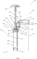
- Figure 1 showed a schematic longitudinal section of a side view of an exemplary embodiment of a device 100 for providing a bone cement dough from two starting components in an initial state.
- the device 100 comprises a mixing unit 200 and a reservoir 300, which are connected to one another via two positive connections (see also Figure 3 ).
- the mixing unit 200 is constructed like a tube and includes a hollow cylindrical cartridge 210 with an interior 215 in which a bone cement powder 500 is stored as a first starting component.
- a proximal cartridge end 211 of the cartridge 210 is with a reversibly detachable cartridge head 220 and the proximal cartridge end 211 axially opposite distal cartridge end 212 is closed in a fluid-conducting manner with a discharge piston 280 which can be moved axially in the interior 215.
- the cartridge 210 and the cartridge head 220 are constructed from two components. In further embodiments, not shown, the cartridge 210 and the cartridge head 220 can be designed in one piece.
- the cartridge head 220 has a cartridge head passage 226 through which a mixing tube 230 is inserted into the interior 215 in an axially movable manner.
- a screw thread 235 on the cartridge head 220 can fix the mixing tube 230 by a screwing movement so that the mixing tube 210 can no longer be moved axially in the interior 215.
- a mixing rod 240 is arranged within the mixing tube 230, which is detachably attached to the mixing tube 230 via a detachable handle 250 at a proximal end of the mixing tube and can thus be moved axially in the interior 215 together with the mixing tube 230.
- the handle 250 serves to simplify the handling of the device 100 by a user by facilitating axial movement of the mixing tube 230 together with the mixing rod 240 within the interior 215.
- the mixing tube 230 is equipped with a mixing element 245 in the form of a mixing disk, which facilitates mixing of the bone cement dough in the interior 215 by axially displacing the mixing tube 230 within the interior 215.
- a tube-shaped vacuum connection 260 is attached to the cartridge head 220, via which the interior 215 can be connected to a vacuum source (not shown) in a fluid-conducting manner.
- the reservoir 300 has a tube-like reservoir container 320, in which two ampoules 330 are stored next to each other (in the view shown, only one of the ampoules 330 is visible, the second ampoule 330 is stored next to the ampoule 330 shown behind the drawing plane).
- the ampoules 330 have an ampoule body 331, an ampoule head 332 facing the mixing unit 200 and an ampoule neck 333 lying between the ampoule body 331 and the ampoule head 332, which acts as a predetermined breaking point for the ampoules 330.
- a monomer liquid 510 is stored in the ampoules 330 as a second starting component of the bone cement dough.
- the ampoule heads 332 of the ampoules 330 are arranged in sections in a connection 350, which connects a cavity 340 of the reservoir 300 to the ampoules 330.
- the connection 350 has a connection diameter 355, which is approximately 5% larger than a diameter of the ampoule heads, so that the connection 350 and the ampoule heads 332 are fixed against tilting within the plane of the drawing.
- the reservoir container 320 has a deformable region 325 in the area of a transition from connection 350 to ampoule body 331.
- a filter element 345 is arranged in the reservoir 300 within the cavity 340, so that fragments of the ampoules 330 cannot get into the mixing unit 200 via the cavity 340 after they have been opened in a fluid-conducting manner, but are retained on the filter element 345.
- the cavity 340 is fluidly connected to the interior 215 of the cartridge 210 via a line 310 in the form of a tube.
- the conduit 310 extends through a cartridge head bushing 225 of the cartridge head 220 into the interior 215.
- the conduit extends approximately over 80% of an interior length 216 of the interior 215, so that in the orientation of the device 100 shown, the monomer liquid 510 can be conveyed directly into the bone cement powder 500 via the conduit 310 and has a sufficiently large distance from the vacuum connection 260 of the mixing unit, so that the risk of the monomer liquid 510 being sucked out of the conduit 310 through the vacuum connection 260 from the interior 215 is reduced.
- the cartridge head bushing 225 and the line means 310 form a first positive connection (see also Figure 3 ), through which the mixing unit 200 and the reservoir 300 are connected to one another.
- the reservoir 300 also has a connecting element 360 in the form of a clasp (see also Figure 2 ), which is arranged in a cuff-like manner around the mixing tube 310 and has a second positive connection (see also Figure 3 ) between mixing unit 200 and reservoir 300.
- a connecting element 360 in the form of a clasp (see also Figure 2 ), which is arranged in a cuff-like manner around the mixing tube 310 and has a second positive connection (see also Figure 3 ) between mixing unit 200 and reservoir 300.
- a slide 270 is arranged on the cartridge head 220, which, after removing the line means 310 from the cartridge head bushing 225, makes the cartridge head bushing 225 closable in a fluid-conducting manner by moving it in the direction of the mixing tube 230.
- FIG 2 shows a schematic side view of a section of the device 100 Figure 1 .
- the connecting element 360 is formed from two clasp notches 361 on an outer surface of the reservoir 300 and a clasp element 362 which can be detached from the two clasp notches 361.
- the clasp element has two protuberances (not shown), which can be inserted into the two clasp notches 261, so that the connecting element 360 can be reversibly closed in a cuff-like manner around the mixing tube 230 in order to ensure the second positive connection in a stable and secure manner between the mixing unit 200 and the reservoir 300 to train.
- the two clasp notches 361 and the two protuberances of the clasp element 362 are triangular, with an outer diameter of the protuberances essentially corresponding to an inner diameter of the clasp notches 261.
- Figure 3 shows the device 100 from the Figures 1 and 2 , wherein the first form fit 400, the second form fit 410 and a pivot point 420 around which the ampoules 330 are tilted against the connection due to the deformable region 325 (cf. Figure 1 ) are pressable, are indicated by filled circles.
- the first form fit 400, the second form fit 410 and the pivot point 420 form a triangle (indicated by connecting lines between the filled circles) in the side view of the device 100 shown. If the ampoules 330 are tilted about the pivot point 420, so that the ampoules 330, in particular the ampoule heads 332 (cf. Figure 1 ), against compound 350 (cf. Figure 1 ). an advantageous distribution of force is achieved. In particular, this can reduce the risk of the conduit 310 kinking or breaking off.
- the first form fit 400, the second form fit 410 and the pivot point 420 are arranged relative to one another such that the second form fit 410 has a shorter distance to the first form fit 400 than the pivot point 420.
- the pivot point 420 and the first form fit 400 are therefore further apart from one another than the first form fit 400 and the second form fit 410. This ensures an improved distribution of the force required when tilting to open the ampoules 330 about the pivot point 420 between the two form fits 400, 410 and at the same time for a design of the device 100 that is as space-saving as possible.
- the latter particularly facilitates the handling of the device 100 by a user.
- the first form fit 400 lies on a straight line 401 running parallel to a longitudinal axis 213 of the cartridge 210
- the second form fit 410 lies on a further straight line 411 running parallel to the longitudinal axis 213 of the cartridge 210, with the longitudinal axis 213 and the straight line 411 through the second form fit 410 are essentially congruent
- the pivot point lies on a further straight line 421 lying parallel to the longitudinal axis 213 of the cartridge 210, the straight lines 401, 411, 421 all having a different straight line distance from the longitudinal axis 213 of the cartridge 210.
- the straight line distance between the straight line 421 through the pivot point and the longitudinal axis 213 is the largest, followed by the straight line distance between the straight line 401 through the first form fit 400 and the longitudinal axis 213.
- the different straight line distances improve the force distribution of the force required when tilting to open the ampoules 330 about the pivot point 420 on the two form fits 400, 410 and at the same time allow the device 100 to be designed to be as space-saving as possible. The latter particularly facilitates the handling of the device 100 by a user.
- Figure 4 shows the device 100 from the Figures 1 to 3 with around the pivot point 420 (cf. Figure 3 ) tilted ampoules 330.
- the reservoir container 320 is bent at the deformable area 325, so that the ampoule heads 332 are pressed against the connection 250 and the ampoules 330 are in the area of the ampoule necks (cf. Figure 1 ) were opened to conduct fluid.
- the monomer liquid 510 stored in the fluid-conducting ampoules 330 has already partially flowed out of the ampoules 330 into the cavity 340.
- One of the two ampoule heads 332 is still arranged in sections in the connection 350, while the other of the two ampoule heads 332 has completely transitioned from the connection 350 into the cavity 3350.
- the ampoule head 332 which had completely passed over into the cavity 340, was caught by the filter element 345, so that it or fragments of it cannot reach or pass through the conduit 310.
- the cavity 340 is dimensioned such that the ampoule heads 332 can be stored in it in a completely rotatable manner, so that any monomer liquid 510 still present in the ampoule head 332 after the ampoules 330 have been opened can flow out into the cavity 340. This is in Figure 4 has already happened with the ampoule head 332 arranged completely in the cavity 340.
- the conduit in particular a diameter of the conduit, is designed in the embodiment of the device 100 shown so that the monomer liquid 510 cannot flow through the conduit 310 into the interior 215 of the cartridge 210 solely due to gravity due to its surface tension.
- the monomer liquid 510 that has flowed out of the ampoules 330 therefore collects in the cavity 340 until active intervention is made by a user of the device 100.
- Figure 5 shows the device 100 from the Figures 1 to 4 when conveying the monomer liquid 510 from the reservoir 300, in particular from the cavity 340 of the reservoir 300, into the interior 215 of the cartridge 210 of the mixing unit 200.
- the monomer liquid 510 has essentially completely flowed out of the ampoules 330.
- the vacuum connection 260 was fluidly connected via a hose 450 to a vacuum source 460 in the form of a vacuum pump. This When the negative pressure source 460 is active, generates a negative pressure in the interior 215 and sucks the monomer liquid 510 from the reservoir 300 into the mixing unit 200.
- the monomer liquid 510 is introduced directly into the bone cement powder 500, which increases the risk of it being sucked out by the Vacuum connection 260 reduced into the vacuum source 460.
- the negative pressure in the interior 215 is maintained at least until the monomer liquid 510 is essentially completely transferred into the mixing unit 200.
- Figure 6 shows the device 100 from the Figures 1 to 5 with bone cement dough 520 provided in the interior 215 and with the reservoir 300 removed.
- the first form fit 400 and the second form fit 410 between the mixing unit 200 and reservoir 300 were released (cf. Figures 1 to 5 ).
- the clasp element 362 was removed from the two clasp notches 261 (cf. Figure 2 ) was pulled out and to release the first positive connection 400, the line means 310 was pulled out of the cartridge head bushing 225 (cf. Figures 1 to 5 ). Due to easier handling, first the second form fit 410 and then the first form fit 400 (cf. Figure 3 ) solved.
- the cartridge head passage 225 was closed in a fluid-conducting manner by pushing in the slide 270, so that the mixing of the bone cement dough 520 can take place with negative pressure applied in the interior 215.
- the mixing tube 230 together with the mixing element 245 was repeatedly moved axially up and down in the interior 215.
- the previously fixed discharge piston 280 was released, so that the negative pressure of the negative pressure source 460 acting in the interior 215 moves the discharge piston 280 in the direction of the cartridge head 220. This allows the bone cement dough 520 to be collected in the area of the cartridge head 220, which makes it easier to later discharge it from the device 100.
- Figure 7 shows the device 100 from the Figures 1 to 6 when discharging the bone cement dough 520.
- the mixing tube 230 was pulled out of the interior 215 through the cartridge head passage 226 until the mixing element 245 rests distally on the cartridge head 220.
- the detachable handle 250 together with the mixing rod 240 were removed from the mixing tube 230 (cf. Figures 1 to 6 ).
- the mixing tube 230 can serve as a fluid-conducting discharge snorkel for the bone cement dough 520 provided. So that the mixing tube 230 is not accidentally pushed back into the interior 215 when discharging the bone cement dough 520, it is reversibly fixed in the cartridge head passage 226 with the screw thread 235.
- the bone cement dough 520 is discharged from the device 100 by advancing the discharge piston 280 in the direction of the cartridge head 220.
- the discharge piston 280 is advanced with the aid of a discharge aid 550 in the form of a discharge gun (only partially shown).
- Figure 8 shows a flowchart of a method 600 for providing a bone cement dough 520 from two starting components using a device 100 according to Figures 1 to 7 comprising steps 610 to 670 and preferably also step 680.
- a step 610 the at least one ampoule 330 in the reservoir 300 is opened in a fluid-conducting manner by tilting it about the pivot point 420 against the connection 350.
- the force required for this is distributed between the two positive connections 400, 410, so that the conduit 310 is prevented from kinking.
- the monomer liquid 510 flows out of the at least one fluid-conducting ampoule 330 opened in step 610 into the cavity 340 of the reservoir 300.
- the outflow of the monomer liquid 510 is caused by gravity.
- the ampoule head 332, further or other fragments of the at least one ampoule 332 are preferably retained in the cavity 340 by a filter element 345, so that this or these cannot penetrate into the conduit 310.
- the monomer liquid 510 is conveyed from the cavity 340 via the conduit 310 into the interior 215 of the cartridge 210 to the bone cement powder 500.
- gravity is used to convey the monomer liquid 510.
- a negative pressure applied in the interior 215 is used to convey the monomer liquid 510, which is preferably provided via a vacuum source 460 connected to the vacuum connection 260, such as a vacuum pump.
- the monomer liquid 510 is preferably conveyed directly into the bone cement powder 500, which can result in better mixing and at the same time reduces or prevents the risk of the monomer liquid 510 being sucked out of the interior 215 when negative pressure is applied via the vacuum connection 260.
- the second form-fitting 410 is released.
- the connecting element 360 is preferably a clasp, so that the clasp element 362 is pulled out of the two clasp notches 361 to release the second form-fitting 410.
- a step 650 the first positive connection 400 is released by pulling the line means 310 out of the cartridge head bushing 225.
- the reservoir 300 is separated from the mixing unit 200 and can be removed. This makes handling the mixing unit 200 easier.
- step 640 occurs before step 650.
- step 650 occurs before step 640.
- conduit 310 is preferably designed as a tube which extends in the interior 215 at least over 70% of the axial interior length 216 of the interior 215, the first alternative is preferred for reasons of easier handling.
- a step 660 the cartridge head passage 225 is closed in a fluid-conducting manner, in particular after the conduit 310 has been removed in step 650. This allows bone cement powder 500 and monomer liquid 510 to be mixed under negative pressure, which can reduce air inclusions in the bone cement dough 520.
- the cartridge head passage 225 is preferably closed by means of a slide 270.
- bone cement powder 500 and monomer liquid 510 are mixed in the interior 215 of the cartridge 210 of the mixing unit 200.
- the monomer liquid 510 is mixed with the bone cement powder 500 by means of the mixing rod 230 with negative pressure applied to form the bone cement dough 520 becomes.
- the Mixing rod 240 is preferably detachably connected to the mixing tube 230, so that an axial movement of the mixing rod 240 is transmitted directly to the mixing tube 230.
- the mixing tube 230 is preferably equipped with the mixing element 245, preferably in the form of a mixing disk, to facilitate mixing. By mixing with negative pressure applied, air pockets in the bone cement dough 520 provided are reduced.
- the mixing rod 240 is detached from the mixing tube 230, preferably by removing the handle 250, and pulled out of the mixing tube 230.
- the mixing tube 230 is pulled out of the cartridge head passage 226 to such an extent that the mixing tube 230 can be used as a discharge snorkel for the bone cement dough 520.
- the advancement of the discharge piston 280 in the direction of the cartridge head 220 is preferably triggered with the aid of a discharge aid 550, such as a discharge gun. This makes it easier for the user to use the device 100.
Landscapes
- Chemical & Material Sciences (AREA)
- Chemical Kinetics & Catalysis (AREA)
- Health & Medical Sciences (AREA)
- Orthopedic Medicine & Surgery (AREA)
- Surgery (AREA)
- Life Sciences & Earth Sciences (AREA)
- Dispersion Chemistry (AREA)
- Medical Informatics (AREA)
- Biomedical Technology (AREA)
- Heart & Thoracic Surgery (AREA)
- Engineering & Computer Science (AREA)
- Molecular Biology (AREA)
- Animal Behavior & Ethology (AREA)
- General Health & Medical Sciences (AREA)
- Public Health (AREA)
- Veterinary Medicine (AREA)
- Nuclear Medicine, Radiotherapy & Molecular Imaging (AREA)
- Materials For Medical Uses (AREA)
- Prostheses (AREA)
- Dental Preparations (AREA)
Priority Applications (4)
| Application Number | Priority Date | Filing Date | Title |
|---|---|---|---|
| EP22174728.0A EP4282518B1 (fr) | 2022-05-23 | 2022-05-23 | Dispositif et procédé de préparation de la pâte de ciment osseux |
| CN202310420935.4A CN117101456A (zh) | 2022-05-23 | 2023-04-19 | 用于制备骨水泥糊状物的装置和方法 |
| AU2023202449A AU2023202449B2 (en) | 2022-05-23 | 2023-04-21 | Device and method for preparing bone cement paste |
| US18/319,222 US20230371995A1 (en) | 2022-05-23 | 2023-05-17 | Device and method for preparing bone cement paste |
Applications Claiming Priority (1)
| Application Number | Priority Date | Filing Date | Title |
|---|---|---|---|
| EP22174728.0A EP4282518B1 (fr) | 2022-05-23 | 2022-05-23 | Dispositif et procédé de préparation de la pâte de ciment osseux |
Publications (2)
| Publication Number | Publication Date |
|---|---|
| EP4282518A1 true EP4282518A1 (fr) | 2023-11-29 |
| EP4282518B1 EP4282518B1 (fr) | 2024-07-03 |
Family
ID=81842058
Family Applications (1)
| Application Number | Title | Priority Date | Filing Date |
|---|---|---|---|
| EP22174728.0A Active EP4282518B1 (fr) | 2022-05-23 | 2022-05-23 | Dispositif et procédé de préparation de la pâte de ciment osseux |
Country Status (4)
| Country | Link |
|---|---|
| US (1) | US20230371995A1 (fr) |
| EP (1) | EP4282518B1 (fr) |
| CN (1) | CN117101456A (fr) |
| AU (1) | AU2023202449B2 (fr) |
Families Citing this family (1)
| Publication number | Priority date | Publication date | Assignee | Title |
|---|---|---|---|---|
| US11973874B1 (en) * | 2023-06-16 | 2024-04-30 | Dk Crown Holdings Inc. | Systems and methods for token metadata management |
Citations (22)
| Publication number | Priority date | Publication date | Assignee | Title |
|---|---|---|---|---|
| US4671263A (en) | 1984-07-11 | 1987-06-09 | Klaus Draenert | Device and process for mixing and applying bone cement |
| DE3640279A1 (de) | 1985-12-23 | 1987-06-25 | Mit Ab | Geraet zum mischen von knochenzement im vakuum |
| US4973168A (en) | 1989-01-13 | 1990-11-27 | Chan Kwan Ho | Vacuum mixing/bone cement cartridge and kit |
| US5344232A (en) | 1991-09-30 | 1994-09-06 | Stryker Corporation | Bone cement mixing and loading apparatus |
| WO1994026403A1 (fr) | 1993-05-10 | 1994-11-24 | Cemvac System Ab | Procede et dispositif permettant d'introduire des constituants d'un ciment pour les os dans un recipient ou ils doivent etre melanges |
| EP0692229A1 (fr) | 1994-07-16 | 1996-01-17 | MERCK PATENT GmbH | Dispositif pour mélanger et appliquer un ciment osseux |
| US5586821A (en) | 1995-10-10 | 1996-12-24 | Zimmer, Inc. | Bone cement preparation kit |
| US5588745A (en) | 1994-09-02 | 1996-12-31 | Howmedica | Methods and apparatus for mixing bone cement components using an evacuated mixing chamber |
| EP0796653A2 (fr) | 1996-02-21 | 1997-09-24 | Kwan-Ho Chan | Dispositif et procédé pour le malaxage d'un ciment pour os |
| US5997544A (en) | 1997-05-02 | 1999-12-07 | Merck Patent Gesellschaft Mit Beschrankter Haftung | Process and device for producing sterile-packed bone cement |
| WO1999067015A1 (fr) | 1997-05-21 | 1999-12-29 | Nikomed Aps | Appareil pour la preparation de ciment osseux |
| US6033105A (en) | 1996-11-15 | 2000-03-07 | Barker; Donald | Integrated bone cement mixing and dispensing system |
| EP1005901A2 (fr) | 1995-11-13 | 2000-06-07 | Cemvac System Aktiebolag | Procédé et dispositif pour mélanger des composants pour un ciment osseux dans un récipient de mélange |
| EP1020167A2 (fr) | 1999-01-14 | 2000-07-19 | Bristol-Myers Squibb Company | Dispositif et procédé pour mélanger et appliquer du ciment osseux |
| DE69812726T2 (de) | 1998-12-14 | 2004-02-05 | Ao Research Institute | Methode und vorrichtung zur herstellung von knochenzement |
| EP1886647A1 (fr) | 2006-08-11 | 2008-02-13 | Biomet Cementing Technologies AB | Dispositif de mélangeur de ciment osseux |
| DE102009031178B3 (de) | 2009-06-29 | 2010-09-16 | Heraeus Medical Gmbh | Vorrichtung zum Mischen und Austragen von Knochenzement |
| EP2404864A1 (fr) | 2010-07-07 | 2012-01-11 | Heraeus Medical GmbH | Brise-ampoule |
| WO2012038002A1 (fr) | 2010-09-22 | 2012-03-29 | Heraeus Medical Gmbh | Dispositif de mélange pour système de cimentation sous vide à pré-emballage, système de cimentation sous vide et procédé |
| EP2578308A2 (fr) * | 2011-10-04 | 2013-04-10 | G21 S.r.l. | Appareil et procédé pour la préparation de ciments osseux |
| EP3150155A1 (fr) * | 2015-10-02 | 2017-04-05 | Heraeus Medical GmbH | Dispositif et procédé de mélange et de stockage d'un ciment à os |
| EP3260192A1 (fr) * | 2016-06-08 | 2017-12-27 | Heraeus Medical GmbH | Dispositif de stockage et de mélange destiné à produire un ciment osseux et procédé pour mélanger un ciment osseux |
-
2022
- 2022-05-23 EP EP22174728.0A patent/EP4282518B1/fr active Active
-
2023
- 2023-04-19 CN CN202310420935.4A patent/CN117101456A/zh active Pending
- 2023-04-21 AU AU2023202449A patent/AU2023202449B2/en active Active
- 2023-05-17 US US18/319,222 patent/US20230371995A1/en active Pending
Patent Citations (26)
| Publication number | Priority date | Publication date | Assignee | Title |
|---|---|---|---|---|
| US4671263A (en) | 1984-07-11 | 1987-06-09 | Klaus Draenert | Device and process for mixing and applying bone cement |
| DE3640279A1 (de) | 1985-12-23 | 1987-06-25 | Mit Ab | Geraet zum mischen von knochenzement im vakuum |
| US4973168A (en) | 1989-01-13 | 1990-11-27 | Chan Kwan Ho | Vacuum mixing/bone cement cartridge and kit |
| US5100241A (en) | 1989-01-13 | 1992-03-31 | Chan Kwan Ho | Vacuum mixing/bone cement cartridge and kit |
| US5344232A (en) | 1991-09-30 | 1994-09-06 | Stryker Corporation | Bone cement mixing and loading apparatus |
| WO1994026403A1 (fr) | 1993-05-10 | 1994-11-24 | Cemvac System Ab | Procede et dispositif permettant d'introduire des constituants d'un ciment pour les os dans un recipient ou ils doivent etre melanges |
| EP0692229A1 (fr) | 1994-07-16 | 1996-01-17 | MERCK PATENT GmbH | Dispositif pour mélanger et appliquer un ciment osseux |
| US5588745A (en) | 1994-09-02 | 1996-12-31 | Howmedica | Methods and apparatus for mixing bone cement components using an evacuated mixing chamber |
| US5586821A (en) | 1995-10-10 | 1996-12-24 | Zimmer, Inc. | Bone cement preparation kit |
| US5624184A (en) | 1995-10-10 | 1997-04-29 | Chan; Kwan-Ho | Bone cement preparation kit having a breakable mixing shaft forming an output port |
| EP1016452A2 (fr) | 1995-11-13 | 2000-07-05 | Cemvac System Aktiebolag | Procédé et dispositif pour mélanger des composants pour un ciment osseux dans un récipient de mélange |
| EP1005901A2 (fr) | 1995-11-13 | 2000-06-07 | Cemvac System Aktiebolag | Procédé et dispositif pour mélanger des composants pour un ciment osseux dans un récipient de mélange |
| EP0796653A2 (fr) | 1996-02-21 | 1997-09-24 | Kwan-Ho Chan | Dispositif et procédé pour le malaxage d'un ciment pour os |
| US6033105A (en) | 1996-11-15 | 2000-03-07 | Barker; Donald | Integrated bone cement mixing and dispensing system |
| US5997544A (en) | 1997-05-02 | 1999-12-07 | Merck Patent Gesellschaft Mit Beschrankter Haftung | Process and device for producing sterile-packed bone cement |
| WO1999067015A1 (fr) | 1997-05-21 | 1999-12-29 | Nikomed Aps | Appareil pour la preparation de ciment osseux |
| DE69812726T2 (de) | 1998-12-14 | 2004-02-05 | Ao Research Institute | Methode und vorrichtung zur herstellung von knochenzement |
| US6709149B1 (en) | 1998-12-14 | 2004-03-23 | Ao Research Institute Davos | Method of bone cement preparation |
| EP1020167A2 (fr) | 1999-01-14 | 2000-07-19 | Bristol-Myers Squibb Company | Dispositif et procédé pour mélanger et appliquer du ciment osseux |
| EP1886647A1 (fr) | 2006-08-11 | 2008-02-13 | Biomet Cementing Technologies AB | Dispositif de mélangeur de ciment osseux |
| DE102009031178B3 (de) | 2009-06-29 | 2010-09-16 | Heraeus Medical Gmbh | Vorrichtung zum Mischen und Austragen von Knochenzement |
| EP2404864A1 (fr) | 2010-07-07 | 2012-01-11 | Heraeus Medical GmbH | Brise-ampoule |
| WO2012038002A1 (fr) | 2010-09-22 | 2012-03-29 | Heraeus Medical Gmbh | Dispositif de mélange pour système de cimentation sous vide à pré-emballage, système de cimentation sous vide et procédé |
| EP2578308A2 (fr) * | 2011-10-04 | 2013-04-10 | G21 S.r.l. | Appareil et procédé pour la préparation de ciments osseux |
| EP3150155A1 (fr) * | 2015-10-02 | 2017-04-05 | Heraeus Medical GmbH | Dispositif et procédé de mélange et de stockage d'un ciment à os |
| EP3260192A1 (fr) * | 2016-06-08 | 2017-12-27 | Heraeus Medical GmbH | Dispositif de stockage et de mélange destiné à produire un ciment osseux et procédé pour mélanger un ciment osseux |
Non-Patent Citations (1)
| Title |
|---|
| CHARNLEY: "J. Anchorage of the femoral head prosthesis of the shaft of the femur", J. BONE JOINT SURG., vol. 42, 1960, pages 28 - 30 |
Also Published As
| Publication number | Publication date |
|---|---|
| AU2023202449B2 (en) | 2024-03-14 |
| US20230371995A1 (en) | 2023-11-23 |
| EP4282518B1 (fr) | 2024-07-03 |
| CN117101456A (zh) | 2023-11-24 |
| AU2023202449A1 (en) | 2023-12-07 |
Similar Documents
| Publication | Publication Date | Title |
|---|---|---|
| EP3643398B1 (fr) | Dispositif et procédé de fourniture de ciment osseux | |
| DE60021633T2 (de) | Hilfswerkzeug zum Auspressen eines chemischen Wirkstoffes, Kneter zum Vorbereiten und Auspressen eines chemischen Wirkstoffes, und Verfahren zur Verwendung derselben | |
| EP3662990B1 (fr) | Dispositif de mélange d'un ciment osseux pourvu de cavité pour un transfert au monomère et procédé | |
| EP2730332B1 (fr) | Dispositif de mélange et d'extraction d'une masse pâteuse | |
| EP3093067B1 (fr) | Dispositif et procédé de melange et de stockage de ciment osseux en polymethacrylate de methyle | |
| EP2987468B1 (fr) | Systeme de cimentation sous vide | |
| EP3505237B1 (fr) | Dispositif et procede de mélange de ciment osseux pourvu d'écarteur dans un logement à ampoule | |
| DE102018131268B4 (de) | Vorrichtung zum Mischen eines Knochenzements mit Hohlraum zum Monomertransfer | |
| EP3584005A1 (fr) | Applicateur de ciment osseux pourvu de bâton mélangeur pouvant être abaissé et procédé de fabrication d'un ciment osseux | |
| EP3415226B1 (fr) | Applicateur de ciment osseux pourvu d'élément conducteur et logement de fermeture | |
| EP3584004A1 (fr) | Applicateur de ciment osseux pourvu de bâton mélangeur pouvant être abaissé et procédé de fabrication d'un ciment osseux | |
| EP4282518B1 (fr) | Dispositif et procédé de préparation de la pâte de ciment osseux | |
| EP3479895B1 (fr) | Mélangeur de ciment osseux, de liquide et de poudre pourvu de raccordement de gaz de pression et procédé | |
| EP4257232B1 (fr) | Dispositif et procédé de préparation de la pâte de ciment osseux | |
| EP4299169B1 (fr) | Dispositif et procédé de fourniture de la pâte de ciment osseux | |
| EP4154973B1 (fr) | Dispositif de préparation de pâte de ciment osseux | |
| EP3838391A1 (fr) | Dispositif de fourniture de ciment osseux | |
| EP4079396B1 (fr) | Dispositif de fourniture de la pâte de ciment osseux | |
| EP4309774A1 (fr) | Dispositif et procédé de fourniture d'une pâte de ciment osseux | |
| DE102018218302A1 (de) | Vorrichtung zum Bereitstellen von Knochenzement | |
| EP4169608A1 (fr) | Dispositif de fourniture d'un composant liquide d'une pâte de ciment osseux, système et procédé de fourniture d'une pâte de ciment osseux | |
| EP3212099B1 (fr) | Dispositif pour appliquer des substituts osseux sous forme de pâte | |
| EP3957261A1 (fr) | Dispositif de détermination de la fluidité d'une pâte de ciment osseux | |
| EP3811881B1 (fr) | Dispositif de distribution du ciment osseux | |
| EP4063007B1 (fr) | Procédé et dispositif de mélange du ciment osseux à dépressurisation |
Legal Events
| Date | Code | Title | Description |
|---|---|---|---|
| PUAI | Public reference made under article 153(3) epc to a published international application that has entered the european phase |
Free format text: ORIGINAL CODE: 0009012 |
|
| STAA | Information on the status of an ep patent application or granted ep patent |
Free format text: STATUS: REQUEST FOR EXAMINATION WAS MADE |
|
| 17P | Request for examination filed |
Effective date: 20220523 |
|
| AK | Designated contracting states |
Kind code of ref document: A1 Designated state(s): AL AT BE BG CH CY CZ DE DK EE ES FI FR GB GR HR HU IE IS IT LI LT LU LV MC MK MT NL NO PL PT RO RS SE SI SK SM TR |
|
| RIC1 | Information provided on ipc code assigned before grant |
Ipc: A61B 17/88 20060101ALN20240308BHEP Ipc: B01F 101/20 20220101ALN20240308BHEP Ipc: B01F 31/441 20220101ALI20240308BHEP Ipc: B01F 35/75 20220101ALI20240308BHEP Ipc: B01F 35/71 20220101ALI20240308BHEP Ipc: B01F 33/501 20220101AFI20240308BHEP |
|
| GRAP | Despatch of communication of intention to grant a patent |
Free format text: ORIGINAL CODE: EPIDOSNIGR1 |
|
| STAA | Information on the status of an ep patent application or granted ep patent |
Free format text: STATUS: GRANT OF PATENT IS INTENDED |
|
| GRAS | Grant fee paid |
Free format text: ORIGINAL CODE: EPIDOSNIGR3 |
|
| INTG | Intention to grant announced |
Effective date: 20240422 |
|
| GRAA | (expected) grant |
Free format text: ORIGINAL CODE: 0009210 |
|
| STAA | Information on the status of an ep patent application or granted ep patent |
Free format text: STATUS: THE PATENT HAS BEEN GRANTED |
|
| AK | Designated contracting states |
Kind code of ref document: B1 Designated state(s): AL AT BE BG CH CY CZ DE DK EE ES FI FR GB GR HR HU IE IS IT LI LT LU LV MC MK MT NL NO PL PT RO RS SE SI SK SM TR |
|
| P01 | Opt-out of the competence of the unified patent court (upc) registered |
Effective date: 20240528 |
|
| REG | Reference to a national code |
Ref country code: CH Ref legal event code: EP |
|
| REG | Reference to a national code |
Ref country code: DE Ref legal event code: R096 Ref document number: 502022001153 Country of ref document: DE |