EP4282518A1 - Device and method for producing bone cement - Google Patents
Device and method for producing bone cement Download PDFInfo
- Publication number
- EP4282518A1 EP4282518A1 EP22174728.0A EP22174728A EP4282518A1 EP 4282518 A1 EP4282518 A1 EP 4282518A1 EP 22174728 A EP22174728 A EP 22174728A EP 4282518 A1 EP4282518 A1 EP 4282518A1
- Authority
- EP
- European Patent Office
- Prior art keywords
- ampoule
- cartridge
- interior
- reservoir
- connection
- Prior art date
- Legal status (The legal status is an assumption and is not a legal conclusion. Google has not performed a legal analysis and makes no representation as to the accuracy of the status listed.)
- Pending
Links
- 239000002639 bone cement Substances 0.000 title claims abstract description 133
- 238000004519 manufacturing process Methods 0.000 title description 5
- 239000000178 monomer Substances 0.000 claims abstract description 93
- 239000007788 liquid Substances 0.000 claims abstract description 90
- 239000000843 powder Substances 0.000 claims abstract description 49
- 239000003708 ampul Substances 0.000 claims description 161
- 238000000034 method Methods 0.000 claims description 14
- 239000000654 additive Substances 0.000 description 14
- 229920003229 poly(methyl methacrylate) Polymers 0.000 description 14
- 239000004926 polymethyl methacrylate Substances 0.000 description 14
- 230000000996 additive effect Effects 0.000 description 12
- 239000003242 anti bacterial agent Substances 0.000 description 7
- 230000005484 gravity Effects 0.000 description 7
- 229920000642 polymer Polymers 0.000 description 7
- 241001295925 Gegenes Species 0.000 description 6
- 229940088710 antibiotic agent Drugs 0.000 description 6
- VVQNEPGJFQJSBK-UHFFFAOYSA-N Methyl methacrylate Chemical compound COC(=O)C(C)=C VVQNEPGJFQJSBK-UHFFFAOYSA-N 0.000 description 5
- 239000012634 fragment Substances 0.000 description 5
- 239000003999 initiator Substances 0.000 description 5
- 239000000463 material Substances 0.000 description 5
- 210000003739 neck Anatomy 0.000 description 5
- VYPSYNLAJGMNEJ-UHFFFAOYSA-N Silicium dioxide Chemical compound O=[Si]=O VYPSYNLAJGMNEJ-UHFFFAOYSA-N 0.000 description 4
- 238000007599 discharging Methods 0.000 description 4
- 239000013543 active substance Substances 0.000 description 3
- 239000012530 fluid Substances 0.000 description 3
- 239000000203 mixture Substances 0.000 description 3
- 239000002245 particle Substances 0.000 description 3
- 238000006116 polymerization reaction Methods 0.000 description 3
- -1 polypropylene Polymers 0.000 description 3
- 239000000126 substance Substances 0.000 description 3
- 230000001960 triggered effect Effects 0.000 description 3
- OMPJBNCRMGITSC-UHFFFAOYSA-N Benzoylperoxide Chemical compound C=1C=CC=CC=1C(=O)OOC(=O)C1=CC=CC=C1 OMPJBNCRMGITSC-UHFFFAOYSA-N 0.000 description 2
- VTYYLEPIZMXCLO-UHFFFAOYSA-L Calcium carbonate Chemical compound [Ca+2].[O-]C([O-])=O VTYYLEPIZMXCLO-UHFFFAOYSA-L 0.000 description 2
- BAPJBEWLBFYGME-UHFFFAOYSA-N Methyl acrylate Chemical compound COC(=O)C=C BAPJBEWLBFYGME-UHFFFAOYSA-N 0.000 description 2
- PPBRXRYQALVLMV-UHFFFAOYSA-N Styrene Chemical compound C=CC1=CC=CC=C1 PPBRXRYQALVLMV-UHFFFAOYSA-N 0.000 description 2
- GWEVSGVZZGPLCZ-UHFFFAOYSA-N Titan oxide Chemical compound O=[Ti]=O GWEVSGVZZGPLCZ-UHFFFAOYSA-N 0.000 description 2
- MCMNRKCIXSYSNV-UHFFFAOYSA-N Zirconium dioxide Chemical compound O=[Zr]=O MCMNRKCIXSYSNV-UHFFFAOYSA-N 0.000 description 2
- TZCXTZWJZNENPQ-UHFFFAOYSA-L barium sulfate Chemical compound [Ba+2].[O-]S([O-])(=O)=O TZCXTZWJZNENPQ-UHFFFAOYSA-L 0.000 description 2
- 235000019400 benzoyl peroxide Nutrition 0.000 description 2
- 210000000988 bone and bone Anatomy 0.000 description 2
- 239000001913 cellulose Substances 0.000 description 2
- 229920002678 cellulose Polymers 0.000 description 2
- 230000001066 destructive effect Effects 0.000 description 2
- 230000001627 detrimental effect Effects 0.000 description 2
- 239000007789 gas Substances 0.000 description 2
- 239000011521 glass Substances 0.000 description 2
- 125000002887 hydroxy group Chemical group [H]O* 0.000 description 2
- GYVGXEWAOAAJEU-UHFFFAOYSA-N n,n,4-trimethylaniline Chemical compound CN(C)C1=CC=C(C)C=C1 GYVGXEWAOAAJEU-UHFFFAOYSA-N 0.000 description 2
- 229920003023 plastic Polymers 0.000 description 2
- 239000004033 plastic Substances 0.000 description 2
- 230000000717 retained effect Effects 0.000 description 2
- 230000002441 reversible effect Effects 0.000 description 2
- 238000000926 separation method Methods 0.000 description 2
- 239000000377 silicon dioxide Substances 0.000 description 2
- 235000012239 silicon dioxide Nutrition 0.000 description 2
- 230000007704 transition Effects 0.000 description 2
- GNFTZDOKVXKIBK-UHFFFAOYSA-N 3-(2-methoxyethoxy)benzohydrazide Chemical compound COCCOC1=CC=CC(C(=O)NN)=C1 GNFTZDOKVXKIBK-UHFFFAOYSA-N 0.000 description 1
- 208000031872 Body Remains Diseases 0.000 description 1
- FGUUSXIOTUKUDN-IBGZPJMESA-N C1(=CC=CC=C1)N1C2=C(NC([C@H](C1)NC=1OC(=NN=1)C1=CC=CC=C1)=O)C=CC=C2 Chemical compound C1(=CC=CC=C1)N1C2=C(NC([C@H](C1)NC=1OC(=NN=1)C1=CC=CC=C1)=O)C=CC=C2 FGUUSXIOTUKUDN-IBGZPJMESA-N 0.000 description 1
- CEAZRRDELHUEMR-URQXQFDESA-N Gentamicin Chemical compound O1[C@H](C(C)NC)CC[C@@H](N)[C@H]1O[C@H]1[C@H](O)[C@@H](O[C@@H]2[C@@H]([C@@H](NC)[C@@](C)(O)CO2)O)[C@H](N)C[C@@H]1N CEAZRRDELHUEMR-URQXQFDESA-N 0.000 description 1
- 229930182566 Gentamicin Natural products 0.000 description 1
- 239000004698 Polyethylene Substances 0.000 description 1
- 239000004743 Polypropylene Substances 0.000 description 1
- 229920002472 Starch Polymers 0.000 description 1
- 238000010521 absorption reaction Methods 0.000 description 1
- 239000012190 activator Substances 0.000 description 1
- 230000003115 biocidal effect Effects 0.000 description 1
- 229910000019 calcium carbonate Inorganic materials 0.000 description 1
- MYPYJXKWCTUITO-KIIOPKALSA-N chembl3301825 Chemical compound O([C@@H]1[C@@H](O)[C@H](O)[C@@H](CO)O[C@H]1OC1=C2C=C3C=C1OC1=CC=C(C=C1Cl)[C@@H](O)[C@H](C(N[C@@H](CC(N)=O)C(=O)N[C@H]3C(=O)N[C@H]1C(=O)N[C@H](C(N[C@H](C3=CC(O)=CC(O)=C3C=3C(O)=CC=C1C=3)C(O)=O)=O)[C@H](O)C1=CC=C(C(=C1)Cl)O2)=O)NC(=O)[C@@H](CC(C)C)NC)[C@H]1C[C@](C)(N)C(O)[C@H](C)O1 MYPYJXKWCTUITO-KIIOPKALSA-N 0.000 description 1
- 229960002227 clindamycin Drugs 0.000 description 1
- KDLRVYVGXIQJDK-AWPVFWJPSA-N clindamycin Chemical compound CN1C[C@H](CCC)C[C@H]1C(=O)N[C@H]([C@H](C)Cl)[C@@H]1[C@H](O)[C@H](O)[C@@H](O)[C@@H](SC)O1 KDLRVYVGXIQJDK-AWPVFWJPSA-N 0.000 description 1
- 150000001875 compounds Chemical class 0.000 description 1
- 238000013270 controlled release Methods 0.000 description 1
- 229920001577 copolymer Polymers 0.000 description 1
- 230000001419 dependent effect Effects 0.000 description 1
- 230000000694 effects Effects 0.000 description 1
- 238000005516 engineering process Methods 0.000 description 1
- 210000000501 femur body Anatomy 0.000 description 1
- 239000000835 fiber Substances 0.000 description 1
- 238000009472 formulation Methods 0.000 description 1
- 229960002518 gentamicin Drugs 0.000 description 1
- 210000004394 hip joint Anatomy 0.000 description 1
- 210000000629 knee joint Anatomy 0.000 description 1
- 229910052751 metal Inorganic materials 0.000 description 1
- 239000002184 metal Substances 0.000 description 1
- 229920000573 polyethylene Polymers 0.000 description 1
- 229920001155 polypropylene Polymers 0.000 description 1
- 239000011148 porous material Substances 0.000 description 1
- 239000007787 solid Substances 0.000 description 1
- 239000008107 starch Substances 0.000 description 1
- 235000019698 starch Nutrition 0.000 description 1
- 230000008961 swelling Effects 0.000 description 1
- 239000004408 titanium dioxide Substances 0.000 description 1
- 235000010215 titanium dioxide Nutrition 0.000 description 1
Images


Classifications
-
- B—PERFORMING OPERATIONS; TRANSPORTING
- B01—PHYSICAL OR CHEMICAL PROCESSES OR APPARATUS IN GENERAL
- B01F—MIXING, e.g. DISSOLVING, EMULSIFYING OR DISPERSING
- B01F25/00—Flow mixers; Mixers for falling materials, e.g. solid particles
- B01F25/30—Injector mixers
- B01F25/31—Injector mixers in conduits or tubes through which the main component flows
-
- A—HUMAN NECESSITIES
- A61—MEDICAL OR VETERINARY SCIENCE; HYGIENE
- A61B—DIAGNOSIS; SURGERY; IDENTIFICATION
- A61B17/00—Surgical instruments, devices or methods, e.g. tourniquets
- A61B17/56—Surgical instruments or methods for treatment of bones or joints; Devices specially adapted therefor
- A61B17/58—Surgical instruments or methods for treatment of bones or joints; Devices specially adapted therefor for osteosynthesis, e.g. bone plates, screws, setting implements or the like
- A61B17/88—Osteosynthesis instruments; Methods or means for implanting or extracting internal or external fixation devices
- A61B17/8802—Equipment for handling bone cement or other fluid fillers
- A61B17/8833—Osteosynthesis tools specially adapted for handling bone cement or fluid fillers; Means for supplying bone cement or fluid fillers to introducing tools, e.g. cartridge handling means
-
- B—PERFORMING OPERATIONS; TRANSPORTING
- B01—PHYSICAL OR CHEMICAL PROCESSES OR APPARATUS IN GENERAL
- B01F—MIXING, e.g. DISSOLVING, EMULSIFYING OR DISPERSING
- B01F33/00—Other mixers; Mixing plants; Combinations of mixers
- B01F33/50—Movable or transportable mixing devices or plants
- B01F33/501—Movable mixing devices, i.e. readily shifted or displaced from one place to another, e.g. portable during use
- B01F33/5011—Movable mixing devices, i.e. readily shifted or displaced from one place to another, e.g. portable during use portable during use, e.g. hand-held
- B01F33/50112—Movable mixing devices, i.e. readily shifted or displaced from one place to another, e.g. portable during use portable during use, e.g. hand-held of the syringe or cartridge type
-
- B—PERFORMING OPERATIONS; TRANSPORTING
- B01—PHYSICAL OR CHEMICAL PROCESSES OR APPARATUS IN GENERAL
- B01F—MIXING, e.g. DISSOLVING, EMULSIFYING OR DISPERSING
- B01F23/00—Mixing according to the phases to be mixed, e.g. dispersing or emulsifying
- B01F23/50—Mixing liquids with solids
- B01F23/51—Methods thereof
-
- B—PERFORMING OPERATIONS; TRANSPORTING
- B01—PHYSICAL OR CHEMICAL PROCESSES OR APPARATUS IN GENERAL
- B01F—MIXING, e.g. DISSOLVING, EMULSIFYING OR DISPERSING
- B01F23/00—Mixing according to the phases to be mixed, e.g. dispersing or emulsifying
- B01F23/50—Mixing liquids with solids
- B01F23/53—Mixing liquids with solids using driven stirrers
-
- B—PERFORMING OPERATIONS; TRANSPORTING
- B01—PHYSICAL OR CHEMICAL PROCESSES OR APPARATUS IN GENERAL
- B01F—MIXING, e.g. DISSOLVING, EMULSIFYING OR DISPERSING
- B01F25/00—Flow mixers; Mixers for falling materials, e.g. solid particles
- B01F25/30—Injector mixers
-
- B—PERFORMING OPERATIONS; TRANSPORTING
- B01—PHYSICAL OR CHEMICAL PROCESSES OR APPARATUS IN GENERAL
- B01F—MIXING, e.g. DISSOLVING, EMULSIFYING OR DISPERSING
- B01F31/00—Mixers with shaking, oscillating, or vibrating mechanisms
- B01F31/44—Mixers with shaking, oscillating, or vibrating mechanisms with stirrers performing an oscillatory, vibratory or shaking movement
- B01F31/441—Mixers with shaking, oscillating, or vibrating mechanisms with stirrers performing an oscillatory, vibratory or shaking movement performing a rectilinear reciprocating movement
-
- B—PERFORMING OPERATIONS; TRANSPORTING
- B01—PHYSICAL OR CHEMICAL PROCESSES OR APPARATUS IN GENERAL
- B01F—MIXING, e.g. DISSOLVING, EMULSIFYING OR DISPERSING
- B01F35/00—Accessories for mixers; Auxiliary operations or auxiliary devices; Parts or details of general application
- B01F35/71—Feed mechanisms
- B01F35/713—Feed mechanisms comprising breaking packages or parts thereof, e.g. piercing or opening sealing elements between compartments or cartridges
- B01F35/7131—Breaking or perforating packages, containers or vials
-
- B—PERFORMING OPERATIONS; TRANSPORTING
- B01—PHYSICAL OR CHEMICAL PROCESSES OR APPARATUS IN GENERAL
- B01F—MIXING, e.g. DISSOLVING, EMULSIFYING OR DISPERSING
- B01F35/00—Accessories for mixers; Auxiliary operations or auxiliary devices; Parts or details of general application
- B01F35/75—Discharge mechanisms
- B01F35/754—Discharge mechanisms characterised by the means for discharging the components from the mixer
- B01F35/75425—Discharge mechanisms characterised by the means for discharging the components from the mixer using pistons or plungers
- B01F35/754251—Discharge mechanisms characterised by the means for discharging the components from the mixer using pistons or plungers reciprocating in the mixing receptacle
-
- A—HUMAN NECESSITIES
- A61—MEDICAL OR VETERINARY SCIENCE; HYGIENE
- A61B—DIAGNOSIS; SURGERY; IDENTIFICATION
- A61B17/00—Surgical instruments, devices or methods, e.g. tourniquets
- A61B17/56—Surgical instruments or methods for treatment of bones or joints; Devices specially adapted therefor
- A61B17/58—Surgical instruments or methods for treatment of bones or joints; Devices specially adapted therefor for osteosynthesis, e.g. bone plates, screws, setting implements or the like
- A61B17/88—Osteosynthesis instruments; Methods or means for implanting or extracting internal or external fixation devices
- A61B17/8802—Equipment for handling bone cement or other fluid fillers
- A61B17/8833—Osteosynthesis tools specially adapted for handling bone cement or fluid fillers; Means for supplying bone cement or fluid fillers to introducing tools, e.g. cartridge handling means
- A61B2017/8838—Osteosynthesis tools specially adapted for handling bone cement or fluid fillers; Means for supplying bone cement or fluid fillers to introducing tools, e.g. cartridge handling means for mixing bone cement or fluid fillers
-
- B—PERFORMING OPERATIONS; TRANSPORTING
- B01—PHYSICAL OR CHEMICAL PROCESSES OR APPARATUS IN GENERAL
- B01F—MIXING, e.g. DISSOLVING, EMULSIFYING OR DISPERSING
- B01F2101/00—Mixing characterised by the nature of the mixed materials or by the application field
- B01F2101/20—Mixing of ingredients for bone cement
Definitions
- the invention further relates to a method for providing a bone cement dough using such a device.
- a further development consists in the development of cementing systems in which both starting components are stored in separate areas of the mixing systems and are only mixed together in the cementing system immediately before the cementing application.
- Such closed, so-called full-prepacked systems are mentioned in the following documents: EP 0 692 229 A1 , DE 10 2009 031 178 B3 , US 5,997,544 A , US 6,709,149 B1 , DE 698 12 726 T2 , EP 0 796 653 A2 , US 5,588,745 A .
- a device in which a monomer liquid is passed from a container via a conduit into an interior of a cartridge filled with a bone cement powder, so that a bone cement dough can be prepared within the cartridge by mixing.
- the conduit and the cartridge are connected to one another via a positive connection. After opening the container, for example by opening a valve, the monomer liquid flows into the interior via the conduit.
- a disadvantage of the disclosed structure of the device is that the method of opening the container may be limited due to the comparatively unstable connection from container to cartridge. For example, opening the container by tilting the ampoule could lead to the conduit being bent.
- a device for opening ampoules comprising an outer container in which a fluid-conducting closed ampoule with an ampoule body and an ampoule head is arranged, and a cavity, wherein the cavity comprises a connection to the ampoule and the ampoule head is arranged at least partially in the connection .
- the walls of the outer container have at least one deformable area, so that the ampoule can be tilted against the connection, which opens the ampoule in a fluid-conducting manner.
- An object of the present invention is to at least partially overcome one or more of the disadvantages resulting from the prior art.
- the invention is based on the aim of providing a device which allows a simple and safe-to-use opening of one or more ampoules, in particular glass ampoules, with a monomer liquid for the simple, quick and safe-to-use provision of a bone cement dough.
- the ampoule or ampoules should be opened with as little effort as possible and while avoiding additional, separate tools.
- the ampoule should be opened with be possible with as few components as possible.
- the monomer liquid should be available for preparing the bone cement dough with as little loss as possible.
- the first positive lock and the second positive lock are reversibly detachable from the mixing unit.
- This embodiment is a second embodiment of the invention, which preferably depends on the first embodiment of the invention.
- the pivot point, the first form fit and the second form fit form the corner points of a triangle in a side view, in particular a side view of the device.
- This embodiment is a third embodiment of the invention, which preferably depends on the first or second embodiment of the invention.
- the second positive connection has a shorter distance, in particular spatial distance, from the first positive connection than the pivot point.
- This embodiment is a fourth embodiment of the invention, which preferably depends on one of the previous embodiments of the invention.
- the first form fit, the second form fit and the pivot point each lie on a straight line running parallel to a longitudinal axis of the cartridge, the straight lines having a different straight line distance, in particular spatial straight line distance, from the longitudinal axis of the cartridge.
- This embodiment is a fifth embodiment of the invention, which preferably depends on one of the previous embodiments of the invention.
- the mixing unit comprises a mixing tube which is arranged axially displaceable in the interior in a cartridge head passage of the cartridge head.
- This embodiment is a sixth embodiment of the invention, which preferably depends on one of the previous embodiments of the invention.
- the second positive connection is formed between the connecting element and the mixing tube.
- This embodiment is a seventh embodiment of the invention, which preferably depends on the sixth embodiment of the invention.
- a detachable mixing rod is arranged within the mixing tube.
- This embodiment is an eighth embodiment of the invention, which preferably depends on the sixth or seventh embodiment of the invention.
- a vacuum connection is arranged on the cartridge head, via which the interior can be connected to a vacuum source, in particular a vacuum pump.
- a vacuum source in particular a vacuum pump.
- the line means is a pipe, a hose or a pipe and a hose, in particular a hose connected to a pipe in a fluid-conducting manner.
- This embodiment is a tenth embodiment of the invention, which preferably depends on one of the previous embodiments of the invention.
- the conduit means is in the
- Cartridge head bushing can be moved axially.
- This embodiment is an eleventh embodiment of the invention, which preferably depends on the tenth embodiment of the invention.
- the conduit extends at least over 70%, preferably at least over 80%, more preferably at least over 90%, of an axial interior length of the interior.
- This embodiment is a twelfth embodiment of the invention, which preferably depends on the tenth or eleventh embodiment of the invention.
- the connecting element is a clasp.
- This embodiment is a thirteenth embodiment of the invention, which preferably depends on one of the previous embodiments of the invention.
- a slide is arranged on the cartridge head in order to close the cartridge head bushing in a fluid-conducting manner after removing the conduit means from the cartridge head bushing, in particular after releasing the first form-fitting connection by removing the conduit means from the cartridge head bushing.
- This embodiment is a fourteenth embodiment of the invention, which preferably depends on one of the previous embodiments of the invention.
- range information also includes the values mentioned as limits.
- a specification of the type "in the range from X to Y" with respect to a quantity A therefore means that A can take on the values X, Y and values between X and Y.
- One-sided limited areas of the type "up to Y" for a size A mean correspondingly as a value Y and smaller than Y.
- a “substantially complete filling of a volume B” includes, for example, a filling of ⁇ 95 to ⁇ 100% by volume of the total volume of B.
- a “substantially complete delivery of a component C” includes, for example, a delivery of ⁇ 90 to ⁇ 100% by volume %, in particular ⁇ 95 to ⁇ 100% by volume, of the total volume of C.
- proximal and distal only serve to designate the spatially opposite ends of the device or other structural units of the device and do not allow any conclusions to be drawn about the orientation in relation to a human body, for example a user of the device. “Distal to ...” and “proximal to ...” or similar formulations only express the spatial arrangement of two structural units of the device relative to one another.
- the device is used to mix a bone cement dough from a bone cement powder and a monomer liquid, with the bone cement powder stored in a mixing unit of the device and the monomer liquid in a reservoir of the device before mixing.
- the reservoir serves to store the monomer liquid before it provides the bone cement dough by mixing it with the bone cement powder in the mixing unit.
- the reservoir has a reservoir container for holding an ampoule filled with the monomer liquid and closed in a fluid-conducting manner, in particular a glass ampoule, with an ampoule head and an ampoule body.
- the reservoir container encloses the ampoule, in particular at least the ampoule body, so that the ampoule can be stored safely in the reservoir until it is used.
- the reservoir container can, for example, be in the form of a hollow cylinder into which the ampoule is inserted, thereby improving Transportability of the device of the reservoir container is shaped, for example, by the reservoir container having a lid, that the ampoule cannot unintentionally emerge from the device, in particular the reservoir.
- the reservoir container is shaped such that two ampoules, in particular two ampoules next to each other, preferably with essentially parallel longitudinal axes, can be stored in the reservoir.
- the reservoir serves to open the at least one fluid-conducting ampoule, which is closed in a fluid-conducting manner.
- the reservoir has a cavity which is connected via a connection to the ampoule arranged in the reservoir container.
- the ampoule is stored in the reservoir in such a way that the ampoule head points in the direction of the cavity, while the ampoule body is at least partially, preferably completely, arranged in the reservoir container.
- the connection extends between the cavity and the reservoir container, in such a way that the ampoule head is arranged in the connection at least in some areas.
- the connection has a connection diameter which allows the ampoule head to be pushed into the connection at least in sections.
- the connection has a connection diameter which allows the ampoule head to be completely pushed into the connection.
- the connection diameter is preferably smaller than the diameter of the ampoule body, so that it cannot be inserted into the connection.
- the connection is designed as a ring or hollow cylinder and the ampoule head is at least partially surrounded by this ring or hollow cylinder.
- the connection has a structural integrity that exceeds a structural integrity of the ampoule, so that when the ampoule is pressed against the connection, the ampoule can break.
- the reservoir container has a deformable region at least in sections, in particular adjacent to a transition from the ampoule head to the ampoule body of the ampoule.
- the reservoir container is completely deformable. The deformable area allows the ampoule to be tilted around a pivot point against the connection.
- connection diameter is matched to the ampoule head in such a way that when tilting, at least the ampoule body end facing away from the ampoule head is tilted about the pivot point, while at least the ampoule head end facing away from the ampoule body remains within the connection, so that the ampoule is caused by at least partial rupture of the ampoule, in particular in the area of an ampoule neck between the ampoule head and the ampoule body, is opened to conduct fluid.
- the connection mainly serves to fix the ampoule head against a tilting movement of the ampoule around the pivot point.
- the connection diameter is no more than 10% larger than the diameter of the ampoule head, so that even a relatively small tilting of the ampoule leads to its fluid-conducting opening.
- the monomer liquid can flow from the ampoule into the cavity.
- the cavity is fluidly connected via a line to the mixing unit, in particular to an interior of the cartridge of the mixing unit, in which the bone cement powder is stored. Conveying the monomer liquid from the cavity via the conduit into the mixing unit can be triggered, for example, by gravity, by a negative pressure in the mixing unit, in particular in the interior of the cartridge, or a combination thereof.
- the reservoir can consist of a wide variety of materials or combinations of materials.
- the reservoir can consist of a polymer.
- the polymer is preferably a transparent polymer, since in this way the user can visually check that the reservoir is functioning properly, in particular that the monomer liquid is flowing out of the at least one ampoule, during use.
- the mixing unit serves to mix the bone cement dough from the bone cement powder and the monomer liquid after conveying the monomer liquid into the mixing unit, in particular into the interior of the mixing unit.
- the mixing unit has a hollow cylindrical cartridge in which the bone cement powder is stored.
- a hollow cylindrical cartridge is to be understood as meaning a tube-like container which has an interior and a cartridge wall surrounding the interior.
- the cross section of the cartridge can take any shape. Due to the simple production and the safer use of the device, the cross section, and preferably also the cross section of the interior, is circular. This allows easy handling for the user and, due to the absence of edges, reduces the risk of moving parts becoming wedged within the device.
- the mixing unit in particular the cartridge, can consist of a wide variety of materials or combinations of materials.
- the mixing unit in particular the cartridge, can consist of a polymer.
- the polymer is preferably a transparent polymer, since in this way the user can visually check that the mixing unit is functioning properly during use.
- the mixing unit is connected in a fluid-conducting manner to the reservoir, in particular to the cavity of the reservoir, via the line means, which extends through a cartridge head passage of the cartridge head at the proximal end of the cartridge.
- Fluid-conducting means that liquids, in particular the monomer liquid, and gases can be exchanged via the conduit between the reservoir and the mixing unit.
- a filter means in particular a pore disk, for example made of sintered polypropylene particles, sintered or pressed polyethylene fibers, cellulose felt or cardboard, is arranged within the conduit, which makes the conduit impermeable to solids. This prevents possible fragments of at least one ampoule from getting into the interior.
- the filter means is preferably arranged at the end of the conduit opposite the cavity, so that no bone cement powder can penetrate into the conduit and can thus close the conduit in a fluid-conducting manner upon contact with the monomer liquid to form the bone cement dough.
- Such a filter means can also be arranged in the cavity in order to intercept possible fragments of the at least one ampoule spatially in front of the conduit means.
- the cartridge head closes the proximal end of the cartridge so that the bone cement powder cannot accidentally escape from the proximal end of the cartridge.
- the cartridge head can be reversibly connected to the cartridge, for example via a screw connection.
- a discharge piston which is axially displaceable in the interior and closes the distal cartridge end in a fluid-conducting manner is arranged on a distal cartridge end axially opposite the proximal cartridge end.
- the bone cement dough can be discharged from the device by advancing the discharge piston in the direction of the proximal end of the cartridge.
- the cartridge head at the proximal cartridge end can be removed, for example by unscrewing, or the cartridge head has an opening for discharging the bone cement dough.
- a locking means can be arranged on the dispensing piston, so that the dispensing piston engages with the cartridge, in particular with the cartridge wall, until the locking means is actively released by a user of the device.
- the mixing unit and the reservoir are connected to one another via two positive connections.
- a first form fit is between the Cartridge head passage of the mixing unit and the conduit of the reservoir and a second positive connection formed between a connecting element of the reservoir and the mixing unit.
- the second positive connection between the connecting element and the mixing unit ensures that the force required to open the at least one ampoule is distributed between the two positive connections, so that the risk of damage to the device when opening the at least one ampoule due to tilting is reduced.
- the reservoir is connected to the mixing unit in such a stable manner that the at least one ampoule can be opened by tilting it about the pivot point against the connection, without damaging the device and without additional aids in addition to the device for opening the at least one ampoule to need.
- the connecting element is connected in one piece to the remaining reservoir, in particular the connection, the cavity and/or the reservoir container.
- the connecting means can be detachably connected to the remaining reservoir, in particular to the connection, the cavity and/or the reservoir container.
- the two form-fitting connections can be designed in such a way that a reversible, in particular non-destructive, separation of the reservoir and the mixing unit is not possible.
- One embodiment of the device is characterized in that the first positive connection and the second positive connection are designed to be detachable from the mixing unit.
- This allows a simple, preferably reversible, non-destructive separation of the reservoir and the mixing unit, so that after the monomer liquid has been conveyed from the at least one cartridge through the conduit into the interior of the cartridge, the reservoir can be easily separated from the mixing unit. Since the reservoir is no longer needed after the monomer liquid has been conveyed into the mixing unit, this can make it easier to provide the bone cement dough to a user, for example through improved handling of the mixing unit.
- the pivot point as well as the first form fit and the second form fit can be spatially arranged in different ways relative to one another.
- One embodiment of the device is characterized in that the pivot point, the first form fit and the second form fit form the corner points of a triangle in a side view, in particular a side view of the device.
- the pivot point and the two positive connections lie in a common plane, but are not arranged on a straight line running in this plane.
- the longitudinal axis of the cartridge lies within this plane or at least runs parallel to this plane.
- the arrangement in the form of a triangle improves the force distribution of the force required to open the at least one ampoule in a fluid-conducting manner, in particular when the ampoule is tilted about the pivot point within or parallel to the plane of the triangle.
- the pivot point is fixed in this plane and does not shift, which makes reproducible opening easier.
- the pivot point as well as the first form fit and the second form fit can have different distances from one another.
- One embodiment of the device is characterized in that the second form fit has a shorter distance to the first form fit than the pivot point.
- the distance between the pivot point and the first form fit is therefore greater than the distance between the second form fit and the first form fit.
- the pivot point and the two positive locks form the corner points of a triangle in a side view, with the pivot point and the second positive lock having the smallest value of the three possible distances between the points mentioned.
- One embodiment of the device is characterized in that the first form fit, the second form fit and the pivot point each lie on a straight line running parallel to a longitudinal axis of the cartridge, the straight lines having a different straight line distance from the longitudinal axis of the cartridge.
- This arrangement improves the force distribution of the force required when tilting to open the ampoule between the two positive locks and at the same time allows the device to be designed to be as space-saving as possible. The latter particularly facilitates the handling of the device by a user.
- the pivot point and the two positive connections form the corner points of a triangle, the triangle lying in a plane in which the longitudinal axis of the cartridge also lies or to which the longitudinal axis of the cartridge at least runs parallel.
- the mixing of the bone cement powder and the monomer liquid within the mixing unit, in particular within the interior of the cartridge, can be carried out in different ways.
- the device or at least the mixing unit if the reservoir has been released from the mixing unit after the monomer liquid has been conveyed from the reservoir into the mixing unit, can be shaken.
- One or more mixing balls for example in the form of metal balls with a diameter of 1 mm to 1 cm, can be provided in the interior, which facilitate thorough mixing of the starting components.
- the mixing unit comprises a mixing tube which is arranged in the interior so as to be axially displaceable in a cartridge head passage of the cartridge head.
- a mixing element for example in the form of a stirrer, can be introduced into the interior through the mixing tube from outside the device in order to mix the starting components after the monomer liquid has been conveyed through the conduit into the interior.
- a mixing element can be pushed so far into the mixing tube that the mixing element protrudes from the mixing tube into the interior and the starting components are mixed by repeatedly moving the mixing tube up and down axially with the mixing element in the cartridge head passage.
- the mixing tube itself has a mixing element in order to mix the starting components by repeatedly moving the mixing tube up and down axially in the cartridge head passage.
- a mixing disk is preferably arranged on a mixing tube end facing the discharge piston.
- the mixing tube can be used as a discharge snorkel for the controlled release of the bone cement dough from the device.
- the mixing tube is preferably pulled axially as far as possible out of the cartridge head passage and then fixed with the cartridge head within the cartridge head passage, for example by means of a screw thread.
- One embodiment of the device is characterized in that a detachable mixing rod is arranged within the mixing tube for improved mixing of the starting components within the interior.
- the mixing rod can represent a mixing element which extends axially through the mixing tube and is firmly connected to the mixing tube for mixing the starting components.
- the mixing rod preferably has a mixing element on a mixing rod end facing the discharge piston.
- the mixing rod makes it easier to operate the mixing tube.
- the mixing rod improves handling of the device and reduces the risk of the mixing tube kinking when mixing the starting components.
- the mixing rod closes the mixing tube in a fluid-conducting manner and thus prevents the starting components from accumulating within the mixing tube, which are not accessible to thorough mixing through the mixing tube within the mixing rod.
- the mixing rod preferably has a handle in order to reversibly move the mixing rod together with the mixing tube connected to it axially up and down in the interior in order to mix the starting components.
- the mixing rod is detachably connected to the mixing tube via the handle, so that the mixing rod can be pulled out of the mixing tube by removing the handle.
- the mixing tube can be used as a discharge snorkel for the bone cement dough.
- the mixing tube is preferably pulled out of the cartridge head passage as far as possible and then firmly connected to the cartridge head in the cartridge head passage, so that the mixing tube is no longer axially movable. This can preferably be done via a screw thread.
- the second positive connection between the reservoir, in particular between the connecting element of the reservoir, and the mixing unit can take place at different points on the mixing unit.
- One embodiment of the device is characterized in that the second positive connection is formed between the connecting element and the mixing tube. This makes it easier to attach the reservoir on the side of the cartridge head opposite the interior and thus facilitates delivery of the monomer liquid through the conduit into the interior. The latter is particularly facilitated when using gravity to convey the monomer liquid.
- the second positive connection allows the device to be designed as simply and as space-saving as possible.
- One embodiment of the device is characterized in that a vacuum connection is arranged on the cartridge head, via which the interior can be connected in a fluid-conducting manner to a vacuum source, such as a vacuum pump.
- the vacuum connection thus allows a negative pressure to be created in the interior, which can be used, for example, to convey the monomer liquid from the reservoir, in particular from the cavity of the reservoir, through the line means into the interior. This allows the monomer liquid to be conveyed easily and quickly into the interior.
- the negative pressure in the interior can be applied or remain applied during the mixing of the bone cement dough from the two starting components. This means that air pockets in the bone cement dough, which could have a detrimental effect on the hardened bone cement, can be reduced or avoided.
- the conduit means can be designed differently in order to direct the monomer liquid into the interior of the cartridge of the mixing unit.
- the conduit is a pipe, a hose or a combination of a pipe and a hose. This allows simple production and easy and space-saving arrangement of the conduit within the interior.
- the conduit is a pipe.
- the conduit in particular in the form of a tube and/or a hose, has a fluid-conducting conduit inner diameter in a range of 0.5 mm to 2 mm, preferably in a range of 0.5 mm to 1.5 mm. Smaller diameters slow down the delivery of the monomer liquid. Larger diameters make it more difficult to essentially completely convey the monomer liquid due to lower capillary effects in the conduit.
- the line means is axially displaceable in the cartridge head bushing, preferably in the interior of the cartridge.
- the cartridge head bushing surrounds the line means in a sleeve-like manner, the line means preferably being a tube.
- the conduit is a flexible tube.
- the conduit extends into or through the cartridge head bushing and can extend to different extents into the interior of the cartridge, in particular axially.
- the line means extends through the cartridge head bushing and is flush with it on the interior side. In this embodiment, the conduit does not extend within the interior.
- One embodiment of the device is characterized in that the conduit extends at least over 70%, preferably at least over 80%, more preferably at least over 90%, of an axial interior length of the interior. This allows, when the device is spatially aligned with the proximal end of the cartridge upwards and the distal end of the cartridge downwards, so that the bone cement powder is in the Stored near the distal end of the cartridge, the monomer liquid is conveyed directly into the bone cement powder stored in the interior, which preferably does not fill the entire interior of the cartridge, but rather, for example, only 20-70% by volume of the total volume of the interior.
- the amount of bone cement powder is selected so that the conduit means can direct the monomer liquid in the vertical orientation of the cartridge with the cartridge head upwards at least onto one surface of the bone cement powder, preferably at least 1 cm deep into the bone cement powder. This makes it easier to mix the initial components of the bone cement dough. Furthermore, the monomer liquid is released in the spatial vicinity of the distal end of the cartridge in the interior, and thus at a comparatively high spatial distance from the vacuum connection on the cartridge head, if present. This prevents the monomer liquid from being sucked into the vacuum connection when a negative pressure is applied to the vacuum connection and is therefore not available for mixing with the bone cement powder.
- the connecting element can be designed differently in order to form the second positive connection between the reservoir and the mixing unit.
- the connecting element is a clasp.
- the clasp is formed from two clasp notches on a reservoir outer surface, such as an outer surface of the reservoir container, the cavity or the connection, and a reversibly detachable clasp element, the clasp element having two protuberances which can be inserted into the two clasp notches, so that the clasp the mixing unit, preferably the mixing tube of the mixing unit, is cuff-like and thus forms the first positive connection.
- This allows a first form fit to be created and released quickly and easily, which is stable and allows the at least one ampoule to be opened safely by tilting it around the pivot point.
- One embodiment of the device is characterized in that a slide is arranged on the cartridge head in order to close the cartridge head bushing in a fluid-conducting manner after removing the conduit means from the cartridge head bushing, preferably by pulling the conduit means out of the cartridge head bushing.
- the at least one ampoule is opened in a fluid-conducting manner by tilting the ampoule stored in the reservoir container about the pivot point against the connection.
- the tilting is made possible by the at least partially deformable area of the reservoir container.
- the at least one ampoule is stored in the reservoir in such a way that the ampoule head is arranged at least partially in the connection of the reservoir, so that when the ampoule, in particular the ampoule body in the reservoir container, is tilted about the pivot point, the ampoule head is pressed against the connection and thus its structural Integrity is overcome so that the monomer liquid can flow out of the at least one ampoule.
- the ampoule breaks preferably in the area of the ampoule neck between the ampoule head and the ampoule body.
- step b. the monomer liquid flows out of step a. open ampoule into the cavity of the reservoir.
- the device is preferably held in such a way that the at least one ampoule occupies an angle to the earth's surface in a range of 15-35 °.
- the ampoule head falls into the cavity of the reservoir.
- the cavity is preferably dimensioned such that the ampoule head can be completely accommodated in the cavity and in addition the ampoule head can be rotated in the cavity. This means that any monomer liquid that may be present in the ampoule head can flow out into the cavity according to gravity and is therefore available to provide the bone cement dough.
- the monomer liquid is conveyed from the cavity into the interior via the conduit.
- gravity is used to convey the monomer liquid into the interior.
- the delivery is triggered by a negative pressure in the interior, it being preferred that the negative pressure in the interior is achieved by applying a negative pressure, for example by fluidly connecting the vacuum connection on the cartridge head to a negative pressure source, such as a vacuum pump , is produced.
- the monomer liquid is preferably introduced directly into the bone cement powder by means of the conduit, so that suction of the monomer liquid from the interior through the vacuum connection and into the negative pressure source is avoided.
- step d the second positive connection between the connecting element and the mixing unit, preferably between the connecting element and the mixing tube of the mixing unit, is released.
- step e the first positive connection is released by pulling the conduit out of the cartridge head bushing.
- steps d. and e. can be carried out in any order, it being preferred that first step d. and then step e. to be carried out, since pulling out the line means in step e. is easier if the second form fit has already been released.
- the cartridge head passage is closed in a fluid-conducting manner after the conduit has been pulled out, so that the bone cement dough can be mixed with negative pressure applied.
- the fluid-conducting closure of the cartridge head passage is preferably carried out by actuating the slide.
- step g The bone cement powder and the monomer liquid are mixed to provide the bone cement dough.
- Mixing is preferably carried out with negative pressure applied in the interior. More preferably, the mixing is carried out by moving the mixing tube up and down while actuating the mixing rod in the mixing tube.
- the bone cement dough provided can be dispensed from the device in different ways.
- the bone cement dough can be removed from the interior with a spatula.
- One embodiment of the method is characterized in that after mixing the bone cement dough, the mixing rod used for this purpose is detached from the mixing tube and removed from it by pulling, so that the mixed bone cement dough is removed from the interior through the mixing tube from the device by advancing the discharge piston in the direction of Cartridge head is discharged. This reduces the user's work steps and the tools required to dispense the bone cement dough.
- the device is preferably connected to a discharge aid, in particular a discharge gun, which moves the discharge piston in the direction of the cartridge head and thus presses the bone cement dough out of the interior.
- a discharge aid in particular a discharge gun
- the device is characterized in that it provides a bone cement dough consisting of two starting components.
- a bone cement dough is a substance that is suitable in the field of medical technology to create a stable connection between artificial joints, such as hip and knee joints, and bone material. Hardening turns a bone cement dough into a bone cement.
- These bone cements are preferably polymethyl methacrylate bone cements (PMMA bone cements). PMMA bone cements have long been used in medical applications and go back to the work of Sir Charnley (cf. Charnley, J. Anchorage of the femoral head prosthesis of the shaft of the femur. J. Bone Joint Surg. 1960; 42, 28-30 .).
- PMMA bone cements can be produced from a bone cement powder as the first starting component and a monomer liquid as the second starting component. If the composition is suitable, the two starting components can be stored separately from one another. When the two starting components come into contact, a plastically deformable bone cement dough is created due to the swelling of the polymer components of the bone cement powder. Polymerization of the monomer is initiated by radicals. As the polymerization of the monomer progresses, the viscosity of the bone cement dough increases until it hardens completely.
- a bone cement powder is understood to mean a powder which comprises at least one particulate polymethyl methacrylate and/or one particulate polymethyl methacrylate copolymer. Examples of copolymers are styrene and/or methyl acrylate.
- the bone cement powder may additionally comprise a hydrophilic additive which supports the distribution of the monomer liquid within the bone cement powder.
- the bone cement powder can additionally comprise an initiator, which initiates the polymerization.
- the bone cement powder can additionally comprise an X-ray opaque.
- the bone cement powder can additionally comprise pharmaceutically active substances, such as antibiotics.
- the bone cement powder preferably comprises, as a hydrophilic additive, at least one particulate polymethyl methacrylate and/or a particulate polymethyl methacrylate copolymer, an initiator and an X-ray opaque or consists of these components. More preferably, the bone cement powder comprises at least one particulate polymethyl methacrylate and/or a particulate polymethyl methacrylate copolymer, an initiator, an X-ray opaque and a hydrophilic additive or consists of these components.
- the bone cement powder comprises or consists of at least one particulate polymethyl methacrylate and/or a particulate polymethyl methacrylate copolymer, an initiator, a radiopaque, a hydrophilic additive and an antibiotic.
- the particle size of the particulate polymethyl methacrylate and/or the particulate polymethyl methacrylate copolymer of the bone cement powder can correspond to the sieve fraction of less than 150 ⁇ m, preferably less than 100 ⁇ m.
- the hydrophilic additive can be designed to be particulate and/or fibrous.
- the hydrophilic additive can be slightly soluble, preferably insoluble, in methyl methacrylate.
- the hydrophilic additive can have an absorption capacity of at least 0.6 g of methyl methacrylate per gram of hydrophilic additive.
- the hydrophilic additive can have a chemical substance with at least one OH group. It can preferably be provided that the hydrophilic additive has covalently bonded OH groups on its surface. Examples of such preferred hydrophilic additives can be additives selected from the group comprising cellulose, oxycellulose, starch, titanium dioxide and silicon dioxide, with fumed silicon dioxide being particularly preferred.
- the particle size of the hydrophilic additive of the sieve fraction can correspond to less than 100 ⁇ m, preferably less than 50 ⁇ m and most preferably less than 10 ⁇ m.
- the hydrophilic additive can be contained in an amount of 0.1 to 2.5% by weight based on the total weight of the bone cement powder.
- the initiator can contain dibenzoyl peroxide or consist of dibenzoyl peroxide.
- a radiopaque is understood to mean a substance which allows the bone cement to be made visible on x-ray diagnostic images.
- radiopaques may include barium sulfate, zirconia and calcium carbonate.
- the pharmaceutically active substance can comprise one or more antibiotics and optionally added co-factors for the one or more antibiotics.
- the pharmaceutically active substance preferably consists of one or more antibiotics and optionally added co-factors for the one or more antibiotics.
- antibiotics include gentamicin, clindamycin and vancomycin.
- the monomer liquid can comprise the monomer methyl methacrylate or consist of methyl methacrylate.
- the monomer liquid comprises, in addition to the monomer, an activator dissolved therein, such as N,N-dimethyl-p-toluidine, or consists of methyl methacrylate and N,N-dimethyl-p-toluidine.
- an activator dissolved therein such as N,N-dimethyl-p-toluidine, or consists of methyl methacrylate and N,N-dimethyl-p-toluidine.
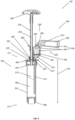
- Figure 1 showed a schematic longitudinal section of a side view of an exemplary embodiment of a device 100 for providing a bone cement dough from two starting components in an initial state.
- the device 100 comprises a mixing unit 200 and a reservoir 300, which are connected to one another via two positive connections (see also Figure 3 ).
- the mixing unit 200 is constructed like a tube and includes a hollow cylindrical cartridge 210 with an interior 215 in which a bone cement powder 500 is stored as a first starting component.
- a proximal cartridge end 211 of the cartridge 210 is with a reversibly detachable cartridge head 220 and the proximal cartridge end 211 axially opposite distal cartridge end 212 is closed in a fluid-conducting manner with a discharge piston 280 which can be moved axially in the interior 215.
- the cartridge 210 and the cartridge head 220 are constructed from two components. In further embodiments, not shown, the cartridge 210 and the cartridge head 220 can be designed in one piece.
- the cartridge head 220 has a cartridge head passage 226 through which a mixing tube 230 is inserted into the interior 215 in an axially movable manner.
- a screw thread 235 on the cartridge head 220 can fix the mixing tube 230 by a screwing movement so that the mixing tube 210 can no longer be moved axially in the interior 215.
- a mixing rod 240 is arranged within the mixing tube 230, which is detachably attached to the mixing tube 230 via a detachable handle 250 at a proximal end of the mixing tube and can thus be moved axially in the interior 215 together with the mixing tube 230.
- the handle 250 serves to simplify the handling of the device 100 by a user by facilitating axial movement of the mixing tube 230 together with the mixing rod 240 within the interior 215.
- the mixing tube 230 is equipped with a mixing element 245 in the form of a mixing disk, which facilitates mixing of the bone cement dough in the interior 215 by axially displacing the mixing tube 230 within the interior 215.
- a tube-shaped vacuum connection 260 is attached to the cartridge head 220, via which the interior 215 can be connected to a vacuum source (not shown) in a fluid-conducting manner.
- the reservoir 300 has a tube-like reservoir container 320, in which two ampoules 330 are stored next to each other (in the view shown, only one of the ampoules 330 is visible, the second ampoule 330 is stored next to the ampoule 330 shown behind the drawing plane).
- the ampoules 330 have an ampoule body 331, an ampoule head 332 facing the mixing unit 200 and an ampoule neck 333 lying between the ampoule body 331 and the ampoule head 332, which acts as a predetermined breaking point for the ampoules 330.
- a monomer liquid 510 is stored in the ampoules 330 as a second starting component of the bone cement dough.
- the ampoule heads 332 of the ampoules 330 are arranged in sections in a connection 350, which connects a cavity 340 of the reservoir 300 to the ampoules 330.
- the connection 350 has a connection diameter 355, which is approximately 5% larger than a diameter of the ampoule heads, so that the connection 350 and the ampoule heads 332 are fixed against tilting within the plane of the drawing.
- the reservoir container 320 has a deformable region 325 in the area of a transition from connection 350 to ampoule body 331.
- a filter element 345 is arranged in the reservoir 300 within the cavity 340, so that fragments of the ampoules 330 cannot get into the mixing unit 200 via the cavity 340 after they have been opened in a fluid-conducting manner, but are retained on the filter element 345.
- the cavity 340 is fluidly connected to the interior 215 of the cartridge 210 via a line 310 in the form of a tube.
- the conduit 310 extends through a cartridge head bushing 225 of the cartridge head 220 into the interior 215.
- the conduit extends approximately over 80% of an interior length 216 of the interior 215, so that in the orientation of the device 100 shown, the monomer liquid 510 can be conveyed directly into the bone cement powder 500 via the conduit 310 and has a sufficiently large distance from the vacuum connection 260 of the mixing unit, so that the risk of the monomer liquid 510 being sucked out of the conduit 310 through the vacuum connection 260 from the interior 215 is reduced.
- the cartridge head bushing 225 and the line means 310 form a first positive connection (see also Figure 3 ), through which the mixing unit 200 and the reservoir 300 are connected to one another.
- the reservoir 300 also has a connecting element 360 in the form of a clasp (see also Figure 2 ), which is arranged in a cuff-like manner around the mixing tube 310 and has a second positive connection (see also Figure 3 ) between mixing unit 200 and reservoir 300.
- a connecting element 360 in the form of a clasp (see also Figure 2 ), which is arranged in a cuff-like manner around the mixing tube 310 and has a second positive connection (see also Figure 3 ) between mixing unit 200 and reservoir 300.
- a slide 270 is arranged on the cartridge head 220, which, after removing the line means 310 from the cartridge head bushing 225, makes the cartridge head bushing 225 closable in a fluid-conducting manner by moving it in the direction of the mixing tube 230.
- FIG 2 shows a schematic side view of a section of the device 100 Figure 1 .
- the connecting element 360 is formed from two clasp notches 361 on an outer surface of the reservoir 300 and a clasp element 362 which can be detached from the two clasp notches 361.
- the clasp element has two protuberances (not shown), which can be inserted into the two clasp notches 261, so that the connecting element 360 can be reversibly closed in a cuff-like manner around the mixing tube 230 in order to ensure the second positive connection in a stable and secure manner between the mixing unit 200 and the reservoir 300 to train.
- the two clasp notches 361 and the two protuberances of the clasp element 362 are triangular, with an outer diameter of the protuberances essentially corresponding to an inner diameter of the clasp notches 261.
- Figure 3 shows the device 100 from the Figures 1 and 2 , wherein the first form fit 400, the second form fit 410 and a pivot point 420 around which the ampoules 330 are tilted against the connection due to the deformable region 325 (cf. Figure 1 ) are pressable, are indicated by filled circles.
- the first form fit 400, the second form fit 410 and the pivot point 420 form a triangle (indicated by connecting lines between the filled circles) in the side view of the device 100 shown. If the ampoules 330 are tilted about the pivot point 420, so that the ampoules 330, in particular the ampoule heads 332 (cf. Figure 1 ), against compound 350 (cf. Figure 1 ). an advantageous distribution of force is achieved. In particular, this can reduce the risk of the conduit 310 kinking or breaking off.
- the first form fit 400, the second form fit 410 and the pivot point 420 are arranged relative to one another such that the second form fit 410 has a shorter distance to the first form fit 400 than the pivot point 420.
- the pivot point 420 and the first form fit 400 are therefore further apart from one another than the first form fit 400 and the second form fit 410. This ensures an improved distribution of the force required when tilting to open the ampoules 330 about the pivot point 420 between the two form fits 400, 410 and at the same time for a design of the device 100 that is as space-saving as possible.
- the latter particularly facilitates the handling of the device 100 by a user.
- the first form fit 400 lies on a straight line 401 running parallel to a longitudinal axis 213 of the cartridge 210
- the second form fit 410 lies on a further straight line 411 running parallel to the longitudinal axis 213 of the cartridge 210, with the longitudinal axis 213 and the straight line 411 through the second form fit 410 are essentially congruent
- the pivot point lies on a further straight line 421 lying parallel to the longitudinal axis 213 of the cartridge 210, the straight lines 401, 411, 421 all having a different straight line distance from the longitudinal axis 213 of the cartridge 210.
- the straight line distance between the straight line 421 through the pivot point and the longitudinal axis 213 is the largest, followed by the straight line distance between the straight line 401 through the first form fit 400 and the longitudinal axis 213.
- the different straight line distances improve the force distribution of the force required when tilting to open the ampoules 330 about the pivot point 420 on the two form fits 400, 410 and at the same time allow the device 100 to be designed to be as space-saving as possible. The latter particularly facilitates the handling of the device 100 by a user.
- Figure 4 shows the device 100 from the Figures 1 to 3 with around the pivot point 420 (cf. Figure 3 ) tilted ampoules 330.
- the reservoir container 320 is bent at the deformable area 325, so that the ampoule heads 332 are pressed against the connection 250 and the ampoules 330 are in the area of the ampoule necks (cf. Figure 1 ) were opened to conduct fluid.
- the monomer liquid 510 stored in the fluid-conducting ampoules 330 has already partially flowed out of the ampoules 330 into the cavity 340.
- One of the two ampoule heads 332 is still arranged in sections in the connection 350, while the other of the two ampoule heads 332 has completely transitioned from the connection 350 into the cavity 3350.
- the ampoule head 332 which had completely passed over into the cavity 340, was caught by the filter element 345, so that it or fragments of it cannot reach or pass through the conduit 310.
- the cavity 340 is dimensioned such that the ampoule heads 332 can be stored in it in a completely rotatable manner, so that any monomer liquid 510 still present in the ampoule head 332 after the ampoules 330 have been opened can flow out into the cavity 340. This is in Figure 4 has already happened with the ampoule head 332 arranged completely in the cavity 340.
- the conduit in particular a diameter of the conduit, is designed in the embodiment of the device 100 shown so that the monomer liquid 510 cannot flow through the conduit 310 into the interior 215 of the cartridge 210 solely due to gravity due to its surface tension.
- the monomer liquid 510 that has flowed out of the ampoules 330 therefore collects in the cavity 340 until active intervention is made by a user of the device 100.
- Figure 5 shows the device 100 from the Figures 1 to 4 when conveying the monomer liquid 510 from the reservoir 300, in particular from the cavity 340 of the reservoir 300, into the interior 215 of the cartridge 210 of the mixing unit 200.
- the monomer liquid 510 has essentially completely flowed out of the ampoules 330.
- the vacuum connection 260 was fluidly connected via a hose 450 to a vacuum source 460 in the form of a vacuum pump. This When the negative pressure source 460 is active, generates a negative pressure in the interior 215 and sucks the monomer liquid 510 from the reservoir 300 into the mixing unit 200.
- the monomer liquid 510 is introduced directly into the bone cement powder 500, which increases the risk of it being sucked out by the Vacuum connection 260 reduced into the vacuum source 460.
- the negative pressure in the interior 215 is maintained at least until the monomer liquid 510 is essentially completely transferred into the mixing unit 200.
- Figure 6 shows the device 100 from the Figures 1 to 5 with bone cement dough 520 provided in the interior 215 and with the reservoir 300 removed.
- the first form fit 400 and the second form fit 410 between the mixing unit 200 and reservoir 300 were released (cf. Figures 1 to 5 ).
- the clasp element 362 was removed from the two clasp notches 261 (cf. Figure 2 ) was pulled out and to release the first positive connection 400, the line means 310 was pulled out of the cartridge head bushing 225 (cf. Figures 1 to 5 ). Due to easier handling, first the second form fit 410 and then the first form fit 400 (cf. Figure 3 ) solved.
- the cartridge head passage 225 was closed in a fluid-conducting manner by pushing in the slide 270, so that the mixing of the bone cement dough 520 can take place with negative pressure applied in the interior 215.
- the mixing tube 230 together with the mixing element 245 was repeatedly moved axially up and down in the interior 215.
- the previously fixed discharge piston 280 was released, so that the negative pressure of the negative pressure source 460 acting in the interior 215 moves the discharge piston 280 in the direction of the cartridge head 220. This allows the bone cement dough 520 to be collected in the area of the cartridge head 220, which makes it easier to later discharge it from the device 100.
- Figure 7 shows the device 100 from the Figures 1 to 6 when discharging the bone cement dough 520.
- the mixing tube 230 was pulled out of the interior 215 through the cartridge head passage 226 until the mixing element 245 rests distally on the cartridge head 220.
- the detachable handle 250 together with the mixing rod 240 were removed from the mixing tube 230 (cf. Figures 1 to 6 ).
- the mixing tube 230 can serve as a fluid-conducting discharge snorkel for the bone cement dough 520 provided. So that the mixing tube 230 is not accidentally pushed back into the interior 215 when discharging the bone cement dough 520, it is reversibly fixed in the cartridge head passage 226 with the screw thread 235.
- the bone cement dough 520 is discharged from the device 100 by advancing the discharge piston 280 in the direction of the cartridge head 220.
- the discharge piston 280 is advanced with the aid of a discharge aid 550 in the form of a discharge gun (only partially shown).
- Figure 8 shows a flowchart of a method 600 for providing a bone cement dough 520 from two starting components using a device 100 according to Figures 1 to 7 comprising steps 610 to 670 and preferably also step 680.
- a step 610 the at least one ampoule 330 in the reservoir 300 is opened in a fluid-conducting manner by tilting it about the pivot point 420 against the connection 350.
- the force required for this is distributed between the two positive connections 400, 410, so that the conduit 310 is prevented from kinking.
- the monomer liquid 510 flows out of the at least one fluid-conducting ampoule 330 opened in step 610 into the cavity 340 of the reservoir 300.
- the outflow of the monomer liquid 510 is caused by gravity.
- the ampoule head 332, further or other fragments of the at least one ampoule 332 are preferably retained in the cavity 340 by a filter element 345, so that this or these cannot penetrate into the conduit 310.
- the monomer liquid 510 is conveyed from the cavity 340 via the conduit 310 into the interior 215 of the cartridge 210 to the bone cement powder 500.
- gravity is used to convey the monomer liquid 510.
- a negative pressure applied in the interior 215 is used to convey the monomer liquid 510, which is preferably provided via a vacuum source 460 connected to the vacuum connection 260, such as a vacuum pump.
- the monomer liquid 510 is preferably conveyed directly into the bone cement powder 500, which can result in better mixing and at the same time reduces or prevents the risk of the monomer liquid 510 being sucked out of the interior 215 when negative pressure is applied via the vacuum connection 260.
- the second form-fitting 410 is released.
- the connecting element 360 is preferably a clasp, so that the clasp element 362 is pulled out of the two clasp notches 361 to release the second form-fitting 410.
- a step 650 the first positive connection 400 is released by pulling the line means 310 out of the cartridge head bushing 225.
- the reservoir 300 is separated from the mixing unit 200 and can be removed. This makes handling the mixing unit 200 easier.
- step 640 occurs before step 650.
- step 650 occurs before step 640.
- conduit 310 is preferably designed as a tube which extends in the interior 215 at least over 70% of the axial interior length 216 of the interior 215, the first alternative is preferred for reasons of easier handling.
- a step 660 the cartridge head passage 225 is closed in a fluid-conducting manner, in particular after the conduit 310 has been removed in step 650. This allows bone cement powder 500 and monomer liquid 510 to be mixed under negative pressure, which can reduce air inclusions in the bone cement dough 520.
- the cartridge head passage 225 is preferably closed by means of a slide 270.
- bone cement powder 500 and monomer liquid 510 are mixed in the interior 215 of the cartridge 210 of the mixing unit 200.
- the monomer liquid 510 is mixed with the bone cement powder 500 by means of the mixing rod 230 with negative pressure applied to form the bone cement dough 520 becomes.
- the Mixing rod 240 is preferably detachably connected to the mixing tube 230, so that an axial movement of the mixing rod 240 is transmitted directly to the mixing tube 230.
- the mixing tube 230 is preferably equipped with the mixing element 245, preferably in the form of a mixing disk, to facilitate mixing. By mixing with negative pressure applied, air pockets in the bone cement dough 520 provided are reduced.
- the mixing rod 240 is detached from the mixing tube 230, preferably by removing the handle 250, and pulled out of the mixing tube 230.
- the mixing tube 230 is pulled out of the cartridge head passage 226 to such an extent that the mixing tube 230 can be used as a discharge snorkel for the bone cement dough 520.
- the advancement of the discharge piston 280 in the direction of the cartridge head 220 is preferably triggered with the aid of a discharge aid 550, such as a discharge gun. This makes it easier for the user to use the device 100.
Abstract
Vorrichtung 100 zum Bereitstellen eines Knochenzementteigs 520 aus zwei Ausgangskomponenten umfassendeine Mischeinheit 200 aufweisend eine hohlzylinderförmige Kartusche 210 mit einem Innenraum 215, wobei in dem Innenraum ein Knochenzementpulver 500 als erste Ausgangskomponente lagert, und einem Kartuschenkopf 220, welcher den Innenraum an einem proximalem Kartuschenende 211 fluidleitend verschließt, undein Reservoir 300 für eine Monomerflüssigkeit 510 als zweite Ausgangskomponente umfassend ein Leitungsmittel 310, welches den Innenraum der Mischeinheit fluidleitend mit dem Reservoir verbindet, wobei sich das Leitungsmittel durch eine Kartuschenkopfdurchführung 225 des Kartuschenkopfs der Mischeinheit erstreckt und das Leitungsmittel und die Kartuschenkopfdurchführung einen ersten Formschluss 400 ausbilden.Device 100 for providing a bone cement dough 520 comprising two starting components, a mixing unit 200 having a hollow cylindrical cartridge 210 with an interior 215, in which a bone cement powder 500 is stored as the first starting component, and a cartridge head 220, which closes the interior in a fluid-conducting manner at a proximal cartridge end 211 , and a reservoir 300 for a monomer liquid 510 as a second output component comprising a line means 310, which connects the interior of the mixing unit to the reservoir in a fluid-conducting manner, the line means extending through a cartridge head feedthrough 225 of the cartridge head of the mixing unit and the line means and the cartridge head feedthrough have a first positive connection 400 form.
Description
Die Erfindung betrifft eine Vorrichtung zum Bereitstellen eines Knochenzementteigs aus zwei Ausgangskomponenten umfassend
- eine Mischeinheit aufweisend eine hohlzylinderförmige Kartusche mit einem Innenraum, wobei in dem Innenraum ein Knochenzementpulver als erste Ausgangskomponente lagert, und einem Kartuschenkopf, welcher den Innenraum an einem proximalem Kartuschenende fluidleitend verschließt, und
- ein Reservoir für eine Monomerflüssigkeit als zweite Ausgangskomponente umfassend ein Leitungsmittel, welches den Innenraum der Mischeinheit fluidleitend mit dem Reservoir verbindet, wobei sich das Leitungsmittel durch eine Kartuschenkopfdurchführung des Kartuschenkopfs der Mischeinheit erstreckt und das Leitungsmittel und die Kartuschenkopfdurchführung einen ersten Formschluss ausbilden.
- a mixing unit having a hollow cylindrical cartridge with an interior, wherein a bone cement powder is stored in the interior as the first starting component, and a cartridge head, which closes the interior at a proximal end of the cartridge in a fluid-conducting manner, and
- a reservoir for a monomer liquid as a second starting component, comprising a conduit which connects the interior of the mixing unit to the reservoir in a fluid-conducting manner, the conduit extending through a cartridge head bushing of the cartridge head of the mixing unit and the conduit and the cartridge head bushing forming a first positive connection.
Die Erfindung betrifft weiterhin ein Verfahren zum Bereitstellen eines Knochenzementteigs mit einer derartigen Vorrichtung.The invention further relates to a method for providing a bone cement dough using such a device.
Es werden erhebliche Bemühungen unternommen, Vorrichtungen und Verfahren zum Bereitstellen von Knochenzementteig aufzuzeigen, mittels derer Knochenzementteig einfach, zuverlässig und schnell bereitgestellt werden kann. Ein wichtiger Aspekt bei der Bereitstellung von Knochenzementteig ist die Vermeidung von Lufteinschlüssen, wie beispielsweise Gasblasen, im Knochenzement. Zu deren Vermeidung wurden eine Vielzahl von Vakuum-Zementiersystemen beschreiben, von denen exemplarisch folgende genannt sind:
Eine Weiterentwicklung besteht in der Entwicklung von Zementiersystemen, in denen beide Ausgangskomponenten in separaten Bereichen der Mischsysteme gelagert sind und erst unmittelbar vor der Zementierapplikation im Zementiersystem miteinander vermischt werden. Solche geschlossenen, sogenannten Full-Prepacked-Systeme, sind in folgenden Schriften genannt:
In der
In der
Es besteht im Markt der Wunsch zur weiteren Vereinfachung von Vorrichtungen zum Bereitstellen von Knochenzementteig.There is a desire in the market to further simplify devices for providing bone cement dough.
Eine Aufgabe der vorliegenden Erfindung ist es, einen oder mehrere der sich aus dem Stand der Technik ergebenen Nachteile zumindest teilweise zu überwinden.An object of the present invention is to at least partially overcome one or more of the disadvantages resulting from the prior art.
Im Speziellen basiert die Erfindung auf dem Ziel, eine Vorrichtung zur Verfügung zu stellen, welche ein einfaches und anwendungssicheres Öffnen einer oder mehrerer Ampullen, insbesondere Glasampullen, mit einer Monomerflüssigkeit zum einfachen, schnellen und anwendungssicheren Bereitstellen eines Knochenzementteigs erlaubt. Insbesondere soll das Öffnen der Ampulle oder der Ampullen mit möglichst wenig Aufwand und unter Vermeidung zusätzlicher, separater Werkzeuge erfolgen. Weiterhin soll das Öffnen der Ampulle mit möglichst wenigen Bauteilen ermöglicht sein. Weiterhin soll die Monomerflüssigkeit möglichst verlustfrei zum Bereitstellen des Knochenzementteigs zur Verfügung stellen.In particular, the invention is based on the aim of providing a device which allows a simple and safe-to-use opening of one or more ampoules, in particular glass ampoules, with a monomer liquid for the simple, quick and safe-to-use provision of a bone cement dough. In particular, the ampoule or ampoules should be opened with as little effort as possible and while avoiding additional, separate tools. Furthermore, the ampoule should be opened with be possible with as few components as possible. Furthermore, the monomer liquid should be available for preparing the bone cement dough with as little loss as possible.
Es ist eine weitere Aufgabe der Erfindung, ein Verfahren bereitzustellen, mit dem Knochenzement aus zwei Ausgangskomponenten bereitgestellt werden kann, mittels dem mindestens ein Teil der bereits beschriebenen Aufgaben zumindest zum Teil gelöst wird.It is a further object of the invention to provide a method with which bone cement can be provided from two starting components, by means of which at least some of the tasks already described are at least partially solved.
Ein Beitrag zur mindestens teilweisen Erfüllung mindestens einer der zuvor genannten Aufgaben wird durch die Merkmale der unabhängigen Ansprüche geleistet. Die abhängigen Ansprüche stellen bevorzugte Ausführungsformen bereit, die zur mindestens teilweisen Erfüllung mindestens einer der Aufgaben beitragen.A contribution to at least partial fulfillment of at least one of the aforementioned tasks is made by the features of the independent claims. The dependent claims provide preferred embodiments that contribute to at least partial fulfillment of at least one of the tasks.
Eine erste Ausführungsform der Erfindung ist eine Vorrichtung zum Bereitstellen eines Knochenzementteigs aus zwei Ausgangskomponenten umfassend
- eine Mischeinheit aufweisend eine hohlzylinderförmige Kartusche mit einem Innenraum, wobei in dem Innenraum ein Knochenzementpulver als erste Ausgangskomponente lagert, und einem Kartuschenkopf, welcher den Innenraum an einem proximalem Kartuschenende fluidleitend verschließt, und
- ein Reservoir für eine Monomerflüssigkeit als zweite Ausgangskomponente umfassend ein Leitungsmittel, welches den Innenraum der Mischeinheit fluidleitend mit dem Reservoir verbindet, wobei sich das Leitungsmittel durch eine Kartuschenkopfdurchführung des Kartuschenkopfs der Mischeinheit erstreckt und das Leitungsmittel und die Kartuschenkopfdurchführung einen ersten Formschluss ausbilden,
- dadurch gekennzeichnet, dass
- das Reservoir einen Reservoirbehälter, in dem mindestens eine fluidleitend geschlossene Ampulle mit einem Ampullenkörper und einem Ampullenkopf angeordnet ist und in der Ampulle die Monomerflüssigkeit lagert, und einen Hohlraum im Bereich des Ampullenkopfs aufweist, wobei der Hohlraum fluidleitend mit dem Leitungsmittel verbunden ist und eine Verbindung zur Ampulle umfasst, wobei der Ampullenkopf zumindest bereichsweise in der Verbindung angeordnet ist und der Reservoirbehälter zumindest abschnittsweise einen verformbaren Bereich umfasst, so dass ein Verkippen der Ampulle um einen Drehpunkt gegen die Verbindung ermöglicht ist,
- wobei die Verbindung einen Verbindungsdurchmesser aufweist, welcher derart an die Abmessungen des Ampullenkopfs angepasst ist, dass der Ampullenkopf bei einem Verkippen der Ampulle um den Drehpunkt gegen die Verbindung fluidleitend öffenbar ist und wobei das Reservoir ein Verbindungselement aufweist, um das Reservoir über einen zweiten Formschluss mit der Mischeinheit zu verbinden.
- a mixing unit having a hollow cylindrical cartridge with an interior, wherein a bone cement powder is stored in the interior as the first starting component, and a cartridge head, which closes the interior at a proximal end of the cartridge in a fluid-conducting manner, and
- a reservoir for a monomer liquid as a second starting component, comprising a conduit which connects the interior of the mixing unit to the reservoir in a fluid-conducting manner, the conduit extending through a cartridge head bushing of the cartridge head of the mixing unit and the conduit and the cartridge head bushing forming a first positive connection,
- characterized in that
- the reservoir is a reservoir container in which at least one fluid-conducting closed ampoule with an ampoule body and an ampoule head is arranged and stores the monomer liquid in the ampoule, and has a cavity in the area of the ampoule head, wherein the cavity is connected to the conduit in a fluid-conducting manner and has a connection to Ampoule, wherein the ampoule head is arranged at least partially in the connection and the reservoir container at least partially comprises a deformable area, so that the ampoule can be tilted about a pivot point against the connection,
- wherein the connection has a connection diameter which is adapted to the dimensions of the ampoule head in such a way that the ampoule head can be opened in a fluid-conducting manner when the ampoule is tilted about the pivot point against the connection and wherein the reservoir has a connecting element in order to connect the reservoir via a second positive connection to connect the mixing unit.
In einer Ausführungsform der Vorrichtung sind der erste Formschluss und der zweite Formschloss reversibel lösbar von der Mischeinheit. Diese Ausführungsform ist eine zweite Ausführungsform der Erfindung, welche vorzugsweise von der ersten Ausführungsform der Erfindung abhängt.In one embodiment of the device, the first positive lock and the second positive lock are reversibly detachable from the mixing unit. This embodiment is a second embodiment of the invention, which preferably depends on the first embodiment of the invention.
In einer Ausführungsform der Vorrichtung bilden der Drehpunkt, der erste Formschluss und der zweite Formschluss in einer Seitenansicht, insbesondere einer Seitenansicht der Vorrichtung, die Eckpunkte eines Dreiecks aus. Diese Ausführungsform ist eine dritte Ausführungsform der Erfindung, welche vorzugsweise von der ersten oder zweiten Ausführungsform der Erfindung abhängt.In one embodiment of the device, the pivot point, the first form fit and the second form fit form the corner points of a triangle in a side view, in particular a side view of the device. This embodiment is a third embodiment of the invention, which preferably depends on the first or second embodiment of the invention.
In einer Ausführungsform der Vorrichtung weist der zweite Formschluss einen kürzeren Abstand, insbesondere räumlichen Abstand, zum ersten Formschluss als der Drehpunkt auf. Diese Ausführungsform ist eine vierte Ausführungsform der Erfindung, welche vorzugsweise von einer der vorhergehenden Ausführungsformen der Erfindung abhängt.In one embodiment of the device, the second positive connection has a shorter distance, in particular spatial distance, from the first positive connection than the pivot point. This embodiment is a fourth embodiment of the invention, which preferably depends on one of the previous embodiments of the invention.
In einer Ausführungsform der Vorrichtung liegen der erste Formschluss, der zweite Formschluss und der Drehpunkt jeweils auf einer parallel zu einer Längsachse der Kartusche verlaufenden Geraden, wobei die Geraden einen unterschiedlichen Geradenabstand, insbesondere räumlichen Geradenabstand, zur Längsachse der Kartusche aufweisen. Diese Ausführungsform ist eine fünfte Ausführungsform der Erfindung, welche vorzugsweise von einer der vorhergehenden Ausführungsformen der Erfindung abhängt.In one embodiment of the device, the first form fit, the second form fit and the pivot point each lie on a straight line running parallel to a longitudinal axis of the cartridge, the straight lines having a different straight line distance, in particular spatial straight line distance, from the longitudinal axis of the cartridge. This embodiment is a fifth embodiment of the invention, which preferably depends on one of the previous embodiments of the invention.
In einer Ausführungsform der Vorrichtung umfasst die Mischeinheit ein Mischrohr, welches axial im Innenraum verschiebbar in einer Kartuschenkopfdurchleitung des Kartuschenkopfs angeordnet ist. Diese Ausführungsform ist eine sechste Ausführungsform der Erfindung, welche vorzugsweise von einer der vorhergehenden Ausführungsformen der Erfindung abhängt.In one embodiment of the device, the mixing unit comprises a mixing tube which is arranged axially displaceable in the interior in a cartridge head passage of the cartridge head. This embodiment is a sixth embodiment of the invention, which preferably depends on one of the previous embodiments of the invention.
In einer Ausführungsform der Vorrichtung ist der zweite Formschluss zwischen dem Verbindungselement und dem Mischrohr ausgebildet. Diese Ausführungsform ist eine siebte Ausführungsform der Erfindung, welche vorzugsweise von der sechsten Ausführungsform der Erfindung abhängt.In one embodiment of the device, the second positive connection is formed between the connecting element and the mixing tube. This embodiment is a seventh embodiment of the invention, which preferably depends on the sixth embodiment of the invention.
In einer Ausführungsform der Vorrichtung ist innerhalb des Mischrohrs ein lösbarer Mischstab angeordnet. Diese Ausführungsform ist eine achte Ausführungsform der Erfindung, welche vorzugsweise von der sechsten oder siebten Ausführungsform der Erfindung abhängt.In one embodiment of the device, a detachable mixing rod is arranged within the mixing tube. This embodiment is an eighth embodiment of the invention, which preferably depends on the sixth or seventh embodiment of the invention.
In einer Ausführungsform der Vorrichtung ist am Kartuschenkopf ein Vakuumanschluss angeordnet, über den der Innenraum mit einer Unterdruckquelle, insbesondere einer Vakuumpumpe, verbindbar ist. Diese Ausführungsform ist eine neunte Ausführungsform der Erfindung, welche vorzugsweise von einer der vorhergehenden Ausführungsformen der Erfindung abhängt.In one embodiment of the device, a vacuum connection is arranged on the cartridge head, via which the interior can be connected to a vacuum source, in particular a vacuum pump. This embodiment is a ninth embodiment of the invention, which preferably depends on one of the previous embodiments of the invention.
In einer Ausführungsform der Vorrichtung ist das Leitungsmittel ein Rohr, ein Schlauch oder ein Rohr und ein Schlauch, insbesondere ein mit einem Rohr fluidleitend verbundener Schlauch. Diese Ausführungsform ist eine zehnte Ausführungsform der Erfindung, welche vorzugsweise von einer der vorhergehenden Ausführungsformen der Erfindung abhängt.In one embodiment of the device, the line means is a pipe, a hose or a pipe and a hose, in particular a hose connected to a pipe in a fluid-conducting manner. This embodiment is a tenth embodiment of the invention, which preferably depends on one of the previous embodiments of the invention.
In einer Ausführungsform der Vorrichtung ist das Leitungsmittel in derIn one embodiment of the device, the conduit means is in the
Kartuschenkopfdurchführung axial verschiebbar. Diese Ausführungsform ist eine elfte Ausführungsform der Erfindung, welche vorzugsweise von der zehnten Ausführungsform der Erfindung abhängt.Cartridge head bushing can be moved axially. This embodiment is an eleventh embodiment of the invention, which preferably depends on the tenth embodiment of the invention.
In einer Ausführungsform der Vorrichtung erstreckt sich das Leitungsmittel mindestens über 70 %, vorzugsweise mindestens über 80 %, weiter bevorzugt mindestens über 90 %, einer axialen Innenraumlänge des Innenraums. Diese Ausführungsform ist eine zwölfte Ausführungsform der Erfindung, welche vorzugsweise von der zehnten oder elften Ausführungsform der Erfindung abhängt.In one embodiment of the device, the conduit extends at least over 70%, preferably at least over 80%, more preferably at least over 90%, of an axial interior length of the interior. This embodiment is a twelfth embodiment of the invention, which preferably depends on the tenth or eleventh embodiment of the invention.
In einer Ausführungsform der Vorrichtung ist das Verbindungselement eine Spange. Diese Ausführungsform ist eine dreizehnte Ausführungsform der Erfindung, welche vorzugsweise von einer der vorhergehenden Ausführungsformen der Erfindung abhängt.In one embodiment of the device, the connecting element is a clasp. This embodiment is a thirteenth embodiment of the invention, which preferably depends on one of the previous embodiments of the invention.
In einer Ausführungsform der Vorrichtung ist am Kartuschenkopf ein Schieber angeordnet, um die Kartuschenkopfdurchführung nach einem Entfernen des Leitungsmittels aus der Kartuschenkopfdurchführung, insbesondere nach einem Lösen des ersten Formschlusses durch Entfernen des Leitungsmittel aus der Kartuschenkopfdurchführung, fluidleitend zu verschließen. Diese Ausführungsform ist eine vierzehnte Ausführungsform der Erfindung, welche vorzugsweise von einer der vorhergehenden Ausführungsformen der Erfindung abhängt.In one embodiment of the device, a slide is arranged on the cartridge head in order to close the cartridge head bushing in a fluid-conducting manner after removing the conduit means from the cartridge head bushing, in particular after releasing the first form-fitting connection by removing the conduit means from the cartridge head bushing. This embodiment is a fourteenth embodiment of the invention, which preferably depends on one of the previous embodiments of the invention.
Eine fünfzehnte Ausführungsform der Erfindung ist ein Verfahren zum Bereitstellen eines Knochenzementteigs mittels einer Vorrichtung nach einer der vorhergehenden Ausführungsformen der Erfindung, umfassend die Schritte:
- a. Fluidleitendes Öffnen der mindestens einen Ampulle durch Verkippen der im Reservoirbehälter gelagerten Ampulle um den Drehpunkt gegen die Verbindung,
- b. Fließen der Monomerflüssigkeit aus der mindestens einen Ampulle in den Hohlraum,
- c. Fördern der Monomerflüssigkeit aus dem Hohlraum über das Leitungsmittel in den Innenraum,
- d. Lösen des zweiten Formschlusses,
- e. Lösen des ersten Formschlusses durch Herausziehen des Leitungsmittels aus der Kartuschenkopfdurchführung,
- f. Fluidleitendes Verschließen der Kartuschenkopfdurchführung,
- g. Mischen von Knochenzementpulver und Monomerflüssigkeit.
- a. Fluid-conducting opening of the at least one ampoule by tilting the ampoule stored in the reservoir container around the pivot point against the connection,
- b. flow of the monomer liquid from the at least one ampoule into the cavity,
- c. Conveying the monomer liquid from the cavity via the conduit into the interior,
- d. loosening the second form fit,
- e. Loosening the first positive connection by pulling the conduit out of the cartridge head bushing,
- f. Fluid-conducting closure of the cartridge head passage,
- G. Mixing bone cement powder and monomer liquid.
In der vorliegenden Beschreibung beinhalten Bereichsangaben auch die als Grenzen genannten Werte. Eine Angabe der Art "im Bereich von X bis Y" in Bezug auf eine Größe A bedeutet folglich, dass A die Werte X, Y und Werte zwischen X und Y annehmen kann. Einseitig begrenzte Bereiche der Art "bis zu Y" für eine Größe A bedeuten entsprechend als Wert Y und kleiner als Y.In this description, range information also includes the values mentioned as limits. A specification of the type "in the range from X to Y" with respect to a quantity A therefore means that A can take on the values X, Y and values between X and Y. One-sided limited areas of the type "up to Y" for a size A mean correspondingly as a value Y and smaller than Y.
Einige der beschriebenen Merkmale sind mit dem Begriff "im Wesentlichen" verknüpft. Der Begriff "im Wesentlichen" ist so zu verstehen, dass unter realen Bedingungen und Fertigungstechniken eine mathematisch exakte Auslegung von Begrifflichkeiten wie "Überlagerung", "senkrecht", "Durchmesser" oder "Parallelität" nie exakt, sondern nur innerhalb gewisser fertigungstechnischer Fehlertoleranzen gegeben sein kann. Beispielsweise schließen "im Wesentlichen parallele Achsen" einen Winkel von 85 Grad bis 95 Grad zueinander ein und "im Wesentlichen gleiche Volumen" umfassen eine Abweichung von bis zu 5 Volumen-%. Eine "im Wesentlichen aus Kunststoff bestehende Vorrichtung" umfasst beispielsweise einen Kunststoffanteil von ≥95 bis ≤100 Gewichts-%. Eine "im Wesentlichen vollständige Befüllung eines Volumens B" umfasst beispielsweise eine Befüllung von ≥95 bis ≤100 Volumen-% des Gesamtvolumens von B. Ein "im Wesentlichen vollständiges Fördern einer Komponente C" umfasst beispielweise ein Fördern von ≥90 bis ≤100 Volumen-%, insbesondere ≥95 bis ≤100 Volumen-%, des Gesamtvolumens von C.Some of the features described are linked to the term “substantially”. The term "essentially" is to be understood as meaning that under real conditions and manufacturing techniques, a mathematically exact interpretation of terms such as "superposition", "vertical", "diameter" or "parallelism" can never be given exactly, but only within certain manufacturing error tolerances can. For example, "substantially parallel axes" include an angle of 85 degrees to 95 degrees to each other and "substantially equal volumes" include a deviation of up to 5% by volume. A “device consisting essentially of plastic” includes, for example, a plastic content of ≥95 to ≤100% by weight. A “substantially complete filling of a volume B” includes, for example, a filling of ≥95 to ≤100% by volume of the total volume of B. A “substantially complete delivery of a component C” includes, for example, a delivery of ≥90 to ≤100% by volume %, in particular ≥95 to ≤100% by volume, of the total volume of C.
Die Begriffe "proximal" und "distal" dienen lediglich der Bezeichnung der räumlich entgegengesetzten Enden der Vorrichtung oder anderer Struktureinheiten der Vorrichtung und erlauben keinen Rückschluss auf die Orientierung in Bezug zu einem menschlichen Körper, beispielsweise eines Anwenders der Vorrichtung. "Distal zu ..." und "proximal zu..." oder ähnliche Formulierungen drücken entsprechend lediglich die räumliche Anordnung zweier Struktureinheiten der Vorrichtung zueinander aus.The terms “proximal” and “distal” only serve to designate the spatially opposite ends of the device or other structural units of the device and do not allow any conclusions to be drawn about the orientation in relation to a human body, for example a user of the device. “Distal to …” and “proximal to …” or similar formulations only express the spatial arrangement of two structural units of the device relative to one another.
Ein erster Gegenstand der Erfindung betrifft eine Vorrichtung zum Bereitstellen eines Knochenzementteigs aus zwei Ausgangskomponenten umfassend
- eine Mischeinheit aufweisend eine hohlzylinderförmige Kartusche mit einem Innenraum, wobei in dem Innenraum ein Knochenzementpulver als erste Ausgangskomponente lagert, und einem Kartuschenkopf, welcher den Innenraum an einem proximalem Kartuschenende fluidleitend verschließt, und
- ein Reservoir für eine Monomerflüssigkeit als zweite Ausgangskomponente umfassend ein Leitungsmittel, welches den Innenraum der Mischeinheit fluidleitend mit dem Reservoir verbindet, wobei sich das Leitungsmittel durch eine Kartuschenkopfdurchführung des Kartuschenkopfs der Mischeinheit erstreckt und das Leitungsmittel und die Kartuschenkopfdurchführung einen ersten Formschluss ausbilden,
- dadurch gekennzeichnet, dass
- das Reservoir einen Reservoirbehälter, in dem mindestens eine fluidleitend geschlossene Ampulle mit einem Ampullenkörper und einem Ampullenkopf angeordnet ist und in der Ampulle die Monomerflüssigkeit lagert, und einen Hohlraum im Bereich des Ampullenkopfs aufweist, wobei der Hohlraum fluidleitend mit dem Leitungsmittel verbunden ist und eine Verbindung zur Ampulle umfasst, wobei der Ampullenkopf zumindest bereichsweise in der Verbindung angeordnet ist und der Reservoirbehälter zumindest abschnittsweise einen verformbaren Bereich umfasst, so dass ein Verkippen der Ampulle um einen Drehpunkt gegen die Verbindung ermöglicht ist,
- wobei die Verbindung einen Verbindungsdurchmesser aufweist, welcher derart an die Abmessungen des Ampullenkopfs angepasst ist, dass der Ampullenkopf bei einem Verkippen der Ampulle um den Drehpunkt gegen die Verbindung fluidleitend öffenbar ist und wobei das Reservoir ein Verbindungselement aufweist, um das Reservoir über einen zweiten Formschluss mit der Mischeinheit zu verbinden.
- a mixing unit having a hollow cylindrical cartridge with an interior, wherein a bone cement powder is stored in the interior as the first starting component, and one Cartridge head, which closes the interior at a proximal end of the cartridge in a fluid-conducting manner, and
- a reservoir for a monomer liquid as a second starting component, comprising a conduit which connects the interior of the mixing unit to the reservoir in a fluid-conducting manner, the conduit extending through a cartridge head bushing of the cartridge head of the mixing unit and the conduit and the cartridge head bushing forming a first positive connection,
- characterized in that
- the reservoir is a reservoir container in which at least one fluid-conducting closed ampoule with an ampoule body and an ampoule head is arranged and stores the monomer liquid in the ampoule, and has a cavity in the area of the ampoule head, wherein the cavity is connected to the conduit in a fluid-conducting manner and has a connection to Ampoule, wherein the ampoule head is arranged at least partially in the connection and the reservoir container at least partially comprises a deformable area, so that the ampoule can be tilted about a pivot point against the connection,
- wherein the connection has a connection diameter which is adapted to the dimensions of the ampoule head in such a way that the ampoule head can be opened in a fluid-conducting manner when the ampoule is tilted about the pivot point against the connection and wherein the reservoir has a connecting element in order to connect the reservoir via a second positive connection to connect the mixing unit.
Die Vorrichtung dient einem Anmischen eines Knochenzementteigs aus einem Knochenzementpulver und einer Monomerflüssigkeit, wobei vor dem Anmischen das Knochenzementpulver in einer Mischeinheit der Vorrichtung und die Monomerflüssigkeit in einem Reservoir der Vorrichtung lagert.The device is used to mix a bone cement dough from a bone cement powder and a monomer liquid, with the bone cement powder stored in a mixing unit of the device and the monomer liquid in a reservoir of the device before mixing.
Das Reservoir dient dem Lagern der Monomerflüssigkeit, bevor diese durch Mischen mit dem Knochenzementpulver in der Mischeinheit den Knochenzementteig bereitstellt. Dazu weist das Reservoir einen Reservoirbehälter zur Aufnahme einer mit der Monomerflüssigkeit befüllten fluidleitend geschlossenen Ampulle, insbesondere einer Glasampulle, mit einem Ampullenkopf und einem Ampullenkörper auf. Der Reservoirbehälter umschließt die Ampulle, insbesondere zumindest den Ampullenkörper, so dass die Ampulle sicher im Reservoir bis zu ihrer Verwendung lagerbar ist. Der Reservoirbehälter kann beispielsweise in der Form eine Hohlzylinders vorliegen, in den die Ampulle eingeschoben ist, wobei zur verbesserten Transportfähigkeit der Vorrichtung der Reservoirbehälter so ausgeformt ist, beispielsweise indem der Reservoirbehälter einen Deckel aufweist, dass die Ampulle nicht unbeabsichtigt aus der Vorrichtung, insbesondere dem Reservoir, austreten kann. Vorzugsweise ist der Reservoirbehälter so ausgeformt, dass zwei Ampullen, insbesondere zwei Ampullen nebeneinander, vorzugsweise mit im Wesentlichen parallelen Längsachsen, in dem Reservoir gelagert werden können.The reservoir serves to store the monomer liquid before it provides the bone cement dough by mixing it with the bone cement powder in the mixing unit. For this purpose, the reservoir has a reservoir container for holding an ampoule filled with the monomer liquid and closed in a fluid-conducting manner, in particular a glass ampoule, with an ampoule head and an ampoule body. The reservoir container encloses the ampoule, in particular at least the ampoule body, so that the ampoule can be stored safely in the reservoir until it is used. The reservoir container can, for example, be in the form of a hollow cylinder into which the ampoule is inserted, thereby improving Transportability of the device of the reservoir container is shaped, for example, by the reservoir container having a lid, that the ampoule cannot unintentionally emerge from the device, in particular the reservoir. Preferably, the reservoir container is shaped such that two ampoules, in particular two ampoules next to each other, preferably with essentially parallel longitudinal axes, can be stored in the reservoir.
Weiterhin dient das Reservoir dem fluidleitenden Öffnen der mindestens einen fluidleitend geschlossenen Ampulle. Dazu weist das Reservoir einen Hohlraum auf, welcher über eine Verbindung mit der im Reservoirbehälter angeordneten Ampulle verbunden ist. Die Ampulle ist derart im Reservoir gelagert, dass der Ampullenkopf in Richtung des Hohlraums zeigt, während der Ampullenkörper zumindest anteilig, vorzugsweise vollständig, im Reservoirbehälter angeordnet ist. Zwischen Hohlraum und Reservoirbehälter erstreckt sich die Verbindung, und zwar derart, dass der Ampullenkopf zumindest bereichsweise in der Verbindung angeordnet ist. Dazu weist die Verbindung einen Verbindungsdurchmesser auf, welcher ein zumindest abschnittsweises einschieben des Ampullenkopfs in die Verbindung erlaubt. In einer Ausgestaltungsform weist die Verbindung einen Verbindungsdurchmesser auf, welcher ein vollständiges Einschieben des Ampullenkopfs in die Verbindung erlaubt. Bevorzugt ist der Verbindungsdurchmesser kleiner als der Durchmesser des Ampullenkörpers, so dass dieser nicht in die Verbindung einschiebbar ist. Beispielsweise ist die Verbindung als Ring oder Hohlzylinder ausgestaltet und der Ampullenkopf ist zumindest bereichsweise von diesem Ring oder Hohlzylinder umgeben. Die Verbindung weist eine strukturelle Integrität auf, welche eine strukturelle Integrität der Ampulle übersteigt, so dass bei einem Pressen der Ampulle gegen die Verbindung die Ampulle zerbrechen kann.Furthermore, the reservoir serves to open the at least one fluid-conducting ampoule, which is closed in a fluid-conducting manner. For this purpose, the reservoir has a cavity which is connected via a connection to the ampoule arranged in the reservoir container. The ampoule is stored in the reservoir in such a way that the ampoule head points in the direction of the cavity, while the ampoule body is at least partially, preferably completely, arranged in the reservoir container. The connection extends between the cavity and the reservoir container, in such a way that the ampoule head is arranged in the connection at least in some areas. For this purpose, the connection has a connection diameter which allows the ampoule head to be pushed into the connection at least in sections. In one embodiment, the connection has a connection diameter which allows the ampoule head to be completely pushed into the connection. The connection diameter is preferably smaller than the diameter of the ampoule body, so that it cannot be inserted into the connection. For example, the connection is designed as a ring or hollow cylinder and the ampoule head is at least partially surrounded by this ring or hollow cylinder. The connection has a structural integrity that exceeds a structural integrity of the ampoule, so that when the ampoule is pressed against the connection, the ampoule can break.
Um die Ampulle, oder bei der Anwesenheit von zwei oder mehr Ampullen alle Ampullen, zu öffnen, weist der Reservoirbehälter zumindest abschnittsweise, insbesondere angrenzend an einen Übergang des Ampullenkopfs zum Ampullenkörper der Ampulle, einen verformbaren Bereich auf. In einer Ausgestaltungsform ist der Reservoirbehälter vollständig verformbar. Der verformbare Bereich erlaubt ein Verkippen der Ampulle um einen Drehpunkt gegen die Verbindung. Dabei ist der Verbindungsdurchmesser so auf den Ampullenkopf abgestimmt, dass beim Verkippen zumindest das dem Ampullenkopf abgewandte Ampullenkörperende um den Drehpunkt verkippt wird, während zumindest das dem Ampullenkörper abgewandte Ampullenkopfende innerhalb der Verbindung verbleibt, so dass die Ampulle durch ein zumindest teilweises Zerbersten der Ampulle, insbesondere im Bereich eines Ampullenhalses zwischen Ampullenkopf und Ampullenkörper, fluidleitend geöffnet wird. Die Verbindung dient dabei hauptsächlich der Fixierung des Ampullenkopfs gegen eine Kippbewegung der Ampulle um den Drehpunkt. Beispielsweise ist der Verbindungsdurchmesser um nicht mehr als 10 % größer als der Durchmesser des Ampullenkopfs, so dass bereits ein relativ geringes Verkippen der Ampulle zu deren fluidleitenden Öffnung führt..In order to open the ampoule, or all ampoules if two or more ampoules are present, the reservoir container has a deformable region at least in sections, in particular adjacent to a transition from the ampoule head to the ampoule body of the ampoule. In one embodiment, the reservoir container is completely deformable. The deformable area allows the ampoule to be tilted around a pivot point against the connection. The connection diameter is matched to the ampoule head in such a way that when tilting, at least the ampoule body end facing away from the ampoule head is tilted about the pivot point, while at least the ampoule head end facing away from the ampoule body remains within the connection, so that the ampoule is caused by at least partial rupture of the ampoule, in particular in the area of an ampoule neck between the ampoule head and the ampoule body, is opened to conduct fluid. The connection mainly serves to fix the ampoule head against a tilting movement of the ampoule around the pivot point. For example, the connection diameter is no more than 10% larger than the diameter of the ampoule head, so that even a relatively small tilting of the ampoule leads to its fluid-conducting opening.
Nach einem fluidleitenden Öffnen der zumindest einen Ampulle kann die Monomerflüssigkeit aus der Ampulle in den Hohlraum fließen. Der Hohlraum ist über ein Leitungsmittel fluidleitend mit der Mischeinheit, insbesondere mit einem Innenraum der Kartusche der Mischeinheit, in welchem das Knochenzementpulver lagert, verbunden. Ein Fördern der Monomerflüssigkeit aus dem Hohlraum über das Leitungsmittel in die Mischeinheit kann beispielsweise über die Schwerkraft, über einen Unterdruck in der Mischeinheit, insbesondere im Innenraum der Kartusche, oder einer Kombination davon ausgelöst werden.After a fluid-conducting opening of the at least one ampoule, the monomer liquid can flow from the ampoule into the cavity. The cavity is fluidly connected via a line to the mixing unit, in particular to an interior of the cartridge of the mixing unit, in which the bone cement powder is stored. Conveying the monomer liquid from the cavity via the conduit into the mixing unit can be triggered, for example, by gravity, by a negative pressure in the mixing unit, in particular in the interior of the cartridge, or a combination thereof.
Das Reservoir kann aus unterschiedlichsten Materialien oder Materialkombinationen bestehen. Beispiele kann das Reservoir aus einem Polymer bestehen. Bevorzugt handelt es sich bei dem Polymer um ein transparentes Polymer, da der Anwender auf diese Weise eine ordnungsgemäße Funktion des Reservoirs, insbesondere ein Ausfließen der Monomerflüssigkeit aus der zumindest einen Ampulle, während einer Verwendung optisch kontrollieren kann.The reservoir can consist of a wide variety of materials or combinations of materials. For example, the reservoir can consist of a polymer. The polymer is preferably a transparent polymer, since in this way the user can visually check that the reservoir is functioning properly, in particular that the monomer liquid is flowing out of the at least one ampoule, during use.
Die Mischeinheit dient einem Anmischen des Knochenzementteigs aus dem Knochenzementpulver und der Monomerflüssigkeit nach Fördern der Monomerflüssigkeit in die Mischeinheit, insbesondere in den Innenraum der Mischeinheit.The mixing unit serves to mix the bone cement dough from the bone cement powder and the monomer liquid after conveying the monomer liquid into the mixing unit, in particular into the interior of the mixing unit.
Die Mischeinheit weist eine hohlzylinderförmige Kartusche auf, in der das Knochenzementpulver gelagert ist. Unter einer hohlzylinderförmigen Kartusche ist ein rohrartiges Behältnis zu verstehen, welches einen Innenraum und eine den Innenraum umgebende Kartuschenwand aufweist. Der Querschnitt der Kartusche kann beliebige Formen annehmen. Aufgrund der einfachen Fertigung und der anwendungssichereren Verwendung der Vorrichtung ist der Querschnitt, und bevorzugt auch der Querschnitt des Innenraums, kreisförmig ausgestaltet. Dies erlaubt eine gute Handhabbarkeit für den Anwender und reduziert durch eine Abwesenheit von Kanten ein Risiko einer Verkeilung beweglicher Teile innerhalb der Vorrichtung.The mixing unit has a hollow cylindrical cartridge in which the bone cement powder is stored. A hollow cylindrical cartridge is to be understood as meaning a tube-like container which has an interior and a cartridge wall surrounding the interior. The cross section of the cartridge can take any shape. Due to the simple production and the safer use of the device, the cross section, and preferably also the cross section of the interior, is circular. This allows easy handling for the user and, due to the absence of edges, reduces the risk of moving parts becoming wedged within the device.
Die Mischeinheit, insbesondere die Kartusche, kann aus unterschiedlichsten Materialien oder Materialkombinationen bestehen. Beispiele kann die Mischeinheit, insbesondere die Kartusche, aus einem Polymer bestehen. Bevorzugt handelt es sich bei dem Polymer um ein transparentes Polymer, da der Anwender auf diese Weise eine ordnungsgemäße Funktion der Mischeinheit während einer Verwendung optisch kontrollieren kann.The mixing unit, in particular the cartridge, can consist of a wide variety of materials or combinations of materials. For example, the mixing unit, in particular the cartridge, can consist of a polymer. The polymer is preferably a transparent polymer, since in this way the user can visually check that the mixing unit is functioning properly during use.
Die Mischeinheit ist mit dem Reservoir, insbesondere mit dem Hohlraum des Reservoirs, über das Leitungsmittel, welches sich durch eine Kartuschenkopfdurchführung des Kartuschenkopfs am proximalem Kartuschenende erstreckt, fluidleitend verbunden. Fluidleitend bedeutet, dass Flüssigkeiten, insbesondere die Monomerflüssigkeit, und Gase über das Leitungsmittel zwischen dem Reservoir und der Mischeinheit austauschbar sind. Vorzugsweise ist innerhalb des Leitungsmittels ein Filtermittel, insbesondere eine Porenscheibe, beispielsweise aus gesinterten Polypropylenpartikeln, aus gesinterten oder verpressten Polyethylenfasern, aus Cellulosefilz oder aus Pappe, angeordnet, welche das Leitungsmittel für Feststoffe undurchlässig ausgestaltet. Dieses verhindert, dass mögliche Bruchstücke der mindestens einen Ampulle in den Innenraum gelangen können. Bevorzugt ist das Filtermittel am dem Hohlraum gegenüberliegenden Ende des Leitungsmittels angeordnet, so dass kein Knochenzementpulver in das Leitungsmittel eindringen kann und so bei Kontakt mit der Monomerflüssigkeit unter Ausbildung des Knochenzementteigs das Leitungsmittel fluidleitend verschließen kann. Ein deratiges Filtermittel kann auch im Hohlraum angeordnet sein, um mögliche Bruchstücke der mindestens einen Ampulle bereits räumlich vor dem Leitungsmittel abzufangen.The mixing unit is connected in a fluid-conducting manner to the reservoir, in particular to the cavity of the reservoir, via the line means, which extends through a cartridge head passage of the cartridge head at the proximal end of the cartridge. Fluid-conducting means that liquids, in particular the monomer liquid, and gases can be exchanged via the conduit between the reservoir and the mixing unit. Preferably, a filter means, in particular a pore disk, for example made of sintered polypropylene particles, sintered or pressed polyethylene fibers, cellulose felt or cardboard, is arranged within the conduit, which makes the conduit impermeable to solids. This prevents possible fragments of at least one ampoule from getting into the interior. The filter means is preferably arranged at the end of the conduit opposite the cavity, so that no bone cement powder can penetrate into the conduit and can thus close the conduit in a fluid-conducting manner upon contact with the monomer liquid to form the bone cement dough. Such a filter means can also be arranged in the cavity in order to intercept possible fragments of the at least one ampoule spatially in front of the conduit means.
Der Kartuschenkopf verschließt das proximale Kartuschenende, so dass das Knochenzementpulver aus dem proximalen Kartuschenende nicht unbeabsichtigt austreten kann. Vorzugsweise ist der Kartuschenkopf reversibel, beispielsweise über eine Schraubverbindung, mit der Kartusche verbindbar. Vorzugsweise ist an einem dem proximalen Kartuschenende axial gegenüberliegenden distalen Kartuschenende ein axial im Innenraum verschiebbarer Austragskolben angeordnet, welcher das distale Kartuschenende fluidleitend verschließt. Nach einem Bereitstellen des Knochenzementteigs kann der Knochenzementteig durch ein Vortreiben des Austragskolbens in Richtung des proximalen Kartuschenendes aus der Vorrichtung ausgebracht werden. Dazu kann beispielsweise der Kartuschenkopf am proximalen Kartuschenende, beispielsweise durch Abschrauben, entfernt werden oder der Kartuschenkopf weist eine Öffnung zum Austragen des Knochenzementteigs auf.The cartridge head closes the proximal end of the cartridge so that the bone cement powder cannot accidentally escape from the proximal end of the cartridge. Preferably, the cartridge head can be reversibly connected to the cartridge, for example via a screw connection. Preferably, a discharge piston which is axially displaceable in the interior and closes the distal cartridge end in a fluid-conducting manner is arranged on a distal cartridge end axially opposite the proximal cartridge end. After the bone cement dough has been prepared, the bone cement dough can be discharged from the device by advancing the discharge piston in the direction of the proximal end of the cartridge. For this purpose, for example, the cartridge head at the proximal cartridge end can be removed, for example by unscrewing, or the cartridge head has an opening for discharging the bone cement dough.
Um ein ungewolltes Vortreiben des Austragskolbens zu verhindern, kann am Austragskolben ein Rastmittel angeordnet sein, so dass der Austragskolben mit der Kartusche, insbesondere mit der Kartuschenwand, rastet, bis das Rastmittel aktiv von einem Anwender der Vorrichtung gelöst wird.In order to prevent unwanted advancement of the dispensing piston, a locking means can be arranged on the dispensing piston, so that the dispensing piston engages with the cartridge, in particular with the cartridge wall, until the locking means is actively released by a user of the device.
Um den Knochenzementteig bereitzustellen, sind die Mischeinheit und das Reservoir über zwei Formschlüsse miteinander verbunden. Ein erster Formschluss ist zwischen der Kartuschenkopfdurchführung der Mischeinheit und dem Leitungsmittel des Reservoirs und ein zweiter Formschluss zwischen einem Verbindungselement des Reservoirs und der Mischeinheit ausgebildet.In order to provide the bone cement dough, the mixing unit and the reservoir are connected to one another via two positive connections. A first form fit is between the Cartridge head passage of the mixing unit and the conduit of the reservoir and a second positive connection formed between a connecting element of the reservoir and the mixing unit.
Beim Öffnen der mindestens einen Ampulle durch ein Verkippen um den Drehpunkt gegen die Verbindung muss eine ausreichend hohe Kraft auf die Ampulle ausgeübt werden, um die strukturelle Integrität der Ampulle zu überwinden. Diese Kraft erhöht sich zusätzlich bei der Verwendung von mehr als einer Ampulle, wie vorzugsweise zwei Ampullen, falls diese, wie bevorzugt, gleichzeitig durch Verkippen um den Drehpunkt gegen die Verbindung geöffnet werden. Diese Kraft wirkt auf die Kontaktstellen von Reservoir und Mischeinheit übertragen. Falls das Reservoir und die Mischeinheit lediglich über den ersten Formschluss verbunden wären, würde die Kraft zum Öffnen der mindestens einen Ampulle vollständig auf das Leitungsmittel einwirken, so dass es zu einem Abknicken oder gar Abreißens des Leitungsmittels käme, wodurch ein im Wesentlichen vollständiges Fördern der Monomerflüssigkeit aus dem Reservoir in die Mischeinheit, insbesondere den Innenraum erschwert oder gar verhindert würde.When opening the at least one ampoule by tilting it about the pivot point against the connection, a sufficiently high force must be exerted on the ampoule in order to overcome the structural integrity of the ampoule. This force increases additionally when using more than one ampoule, preferably two ampoules, if, as preferred, these are opened simultaneously by tilting about the pivot point against the connection. This force is transmitted to the contact points of the reservoir and mixing unit. If the reservoir and the mixing unit were only connected via the first positive connection, the force for opening the at least one ampoule would act completely on the conduit, so that the conduit would be bent or even torn off, resulting in a substantially complete delivery of the monomer liquid from the reservoir into the mixing unit, especially the interior, would be made more difficult or even prevented.
Der zweite Formschluss zwischen dem Verbindungselement und der Mischeinheit sorgt für eine Kraftverteilung der zum Öffnen der mindestens einen Ampulle benötigten Kraft auf die zwei Formschlüsse, so dass das Risiko eines Beschädigens der Vorrichtung beim Öffnen der mindestens einen Ampulle durch ein Verkippen verringert wird.The second positive connection between the connecting element and the mixing unit ensures that the force required to open the at least one ampoule is distributed between the two positive connections, so that the risk of damage to the device when opening the at least one ampoule due to tilting is reduced.
Durch die zwei Formschlüsse ist das Reservoir derart stabil mit der Mischeinheit verbunden, dass die mindestens eine Ampulle durch ein Verkippen um den Drehpunkt gegen die Verbindung geöffnet werden kann, ohne die Vorrichtung zu beschädigen und ohne zusätzliche Hilfsmittel neben der Vorrichtung zum Öffnen der mindestens einen Ampulle zu benötigen.Due to the two positive locks, the reservoir is connected to the mixing unit in such a stable manner that the at least one ampoule can be opened by tilting it about the pivot point against the connection, without damaging the device and without additional aids in addition to the device for opening the at least one ampoule to need.
In einer Ausgestaltungsform ist das Verbindungselement einteilig mit dem restlichen Reservoir, insbesondere der Verbindung, dem Hohlraum und/oder dem Reservoirbehälter, verbunden. In einer weiteren Ausgestaltungsform ist das Verbindungsmittel lösbar mit dem restlichen Reservoir, insbesondere mit der Verbindung, dem Hohlraum und/oder dem Reservoirbehälter, verbindbar.In one embodiment, the connecting element is connected in one piece to the remaining reservoir, in particular the connection, the cavity and/or the reservoir container. In a further embodiment, the connecting means can be detachably connected to the remaining reservoir, in particular to the connection, the cavity and/or the reservoir container.
Die zwei Formschlüsse können so ausgestaltet sein, dass ein reversibles, insbesondere zerstörungsfreies, Trennen von Reservoir und Mischeinheit nicht möglich ist.The two form-fitting connections can be designed in such a way that a reversible, in particular non-destructive, separation of the reservoir and the mixing unit is not possible.
Eine Ausführungsform der Vorrichtung ist dadurch gekennzeichnet, dass der erste Formschluss und der zweite Formschluss lösbar von der Mischeinheit ausgestaltet sind. Dies erlaubt ein einfaches, vorzugsweise reversibles, zerstörungsfreies Trennen von Reservoir und Mischeinheit, so dass nach dem Fördern der Monomerflüssigkeit aus der mindestens einen Kartusche durch das Leitungsmittel in den Innenraum der Kartusche das Reservoir von der Mischeinheit einfach getrennt werden kann. Da das Reservoir nach dem Fördern der Monomerflüssigkeit in die Mischeinheit nicht mehr benötigt wird, kann dies ein Bereitstellen des Knochenzementteigs für einen Anwender, beispielsweise durch eine verbesserte Handhabung der Mischeinheit, erleichtern.One embodiment of the device is characterized in that the first positive connection and the second positive connection are designed to be detachable from the mixing unit. This allows a simple, preferably reversible, non-destructive separation of the reservoir and the mixing unit, so that after the monomer liquid has been conveyed from the at least one cartridge through the conduit into the interior of the cartridge, the reservoir can be easily separated from the mixing unit. Since the reservoir is no longer needed after the monomer liquid has been conveyed into the mixing unit, this can make it easier to provide the bone cement dough to a user, for example through improved handling of the mixing unit.
Der Drehpunkt sowie der erste Formschluss und der zweite Formschluss können räumlich auf unterschiedliche Weise zueinander angeordnet sein.The pivot point as well as the first form fit and the second form fit can be spatially arranged in different ways relative to one another.
Einer Ausführungsform der Vorrichtung ist dadurch gekennzeichnet, dass der Drehpunkt, der erste Formschluss und der zweite Formschluss in einer Seitenansicht, insbesondere einer Seitenansicht der Vorrichtung, die Eckpunkte eines Dreiecks ausbilden. In dieser Ausführungsform liegen der Drehpunkt und die beiden Formschlüsse in einer gemeinsamen Ebene, sind allerdings nicht auf einer in dieser Ebene verlaufenden Geraden angeordnet. Vorzugsweise liegt die Längsachse der Kartusche innerhalb dieser Ebene oder verläuft zumindest parallel zu dieser Ebene. Die Anordnung in Form eines Dreiecks verbessert die Kraftverteilung der zum fluidleitenden Öffnen der zumindest einen Ampulle benötigten Kraft, insbesondere bei einer dazu verwendeten Verkippbewegung der Ampulle um den Drehpunkt innerhalb oder parallel zu der Ebene des Dreiecks. Weiterhin ist durch eine derartige Anordnung der Drehpunkt in dieser Ebene fixiert und verschiebt sich nicht, was ein reproduzierbares Öffnen erleichtert.One embodiment of the device is characterized in that the pivot point, the first form fit and the second form fit form the corner points of a triangle in a side view, in particular a side view of the device. In this embodiment, the pivot point and the two positive connections lie in a common plane, but are not arranged on a straight line running in this plane. Preferably, the longitudinal axis of the cartridge lies within this plane or at least runs parallel to this plane. The arrangement in the form of a triangle improves the force distribution of the force required to open the at least one ampoule in a fluid-conducting manner, in particular when the ampoule is tilted about the pivot point within or parallel to the plane of the triangle. Furthermore, due to such an arrangement, the pivot point is fixed in this plane and does not shift, which makes reproducible opening easier.
Der Drehpunkt sowie der erste Formschluss und der zweite Formschluss können unterschiedlich große Abstände zueinander aufweisen.The pivot point as well as the first form fit and the second form fit can have different distances from one another.
Eine Ausführungsform der Vorrichtung ist dadurch gekennzeichnet, dass der zweite Formschluss einen kürzeren Abstand zum ersten Formschluss als der Drehpunkt aufweist. In dieser Ausführungsform ist der Abstand zwischen Drehpunkt und erstem Formschluss somit größer als der Abstand zwischen zweitem Formschluss und erstem Formschluss. Insbesondere bei einer Anordnung von Drehpunkt und den zwei Formschlüssen in Form eines Dreiecks erlaubt dies sowohl eine verbesserte Kraftverteilung der beim Verkippen zum Öffnen der Ampulle benötigten Kraft auf die zwei Formschlüsse als auch gleichzeitig eine möglichst platzsparende Ausgestaltung der Vorrichtung. Letzteres erleichtert insbesondere die Handhabung der Vorrichtung durch einen Anwender.One embodiment of the device is characterized in that the second form fit has a shorter distance to the first form fit than the pivot point. In this embodiment, the distance between the pivot point and the first form fit is therefore greater than the distance between the second form fit and the first form fit. Particularly with an arrangement of the pivot point and the two positive locks in the form of a triangle, this allows for improved distribution of force when tilting to open the Ampoule required force on the two positive locks and at the same time a design of the device that was as space-saving as possible. The latter particularly facilitates the handling of the device by a user.
Vorzugsweise bilden dabei der Drehpunkt und die zwei Formschlüsse in einer Seitenansicht die Eckpunkte eines Dreiecks, wobei der Drehpunkt und der zweite Formschluss von den drei möglichen Abständen zwischen den genannten Punkten den geringsten Wert aufweisen. Dies führt zu einer weiteren Verbesserung der Kraftverteilung auf die zwei Formschlüsse und erlaubt eine weiter platzsparende Ausgestaltung der Vorrichtung.Preferably, the pivot point and the two positive locks form the corner points of a triangle in a side view, with the pivot point and the second positive lock having the smallest value of the three possible distances between the points mentioned. This leads to a further improvement in the force distribution between the two positive locks and allows a further space-saving design of the device.
Eine Ausführungsform der Vorrichtung ist dadurch gekennzeichnet, dass der erste Formschluss, der zweite Formschluss und der Drehpunkt jeweils auf einer parallel zu einer Längsachse der Kartusche verlaufenden Geraden liegen, wobei die Geraden einen unterschiedlichen Geradenabstand zur Längsachse der Kartusche aufweisen. Diese Anordnung verbessert die Kraftverteilung der beim Verkippen zum Öffnen der Ampulle benötigten Kraft auf die zwei Formschlüsse und erlaubt auch gleichzeitig eine möglichst platzsparende Ausgestaltung der Vorrichtung. Letzteres erleichtert insbesondere die Handhabung der Vorrichtung durch einen Anwender.One embodiment of the device is characterized in that the first form fit, the second form fit and the pivot point each lie on a straight line running parallel to a longitudinal axis of the cartridge, the straight lines having a different straight line distance from the longitudinal axis of the cartridge. This arrangement improves the force distribution of the force required when tilting to open the ampoule between the two positive locks and at the same time allows the device to be designed to be as space-saving as possible. The latter particularly facilitates the handling of the device by a user.
Vorzugsweise bilden dabei der Drehpunkt und die zwei Formschlüsse die Eckpunkte eines Dreiecks, wobei das Dreieck in einer Ebene liegt, in welcher auch die Längsachse der Kartusche liegt oder zu der die Längsachse der Kartusche zumindest parallel verläuft.Preferably, the pivot point and the two positive connections form the corner points of a triangle, the triangle lying in a plane in which the longitudinal axis of the cartridge also lies or to which the longitudinal axis of the cartridge at least runs parallel.
Das Anmischen des Knochenzementpulvers und der Monomerflüssigkeit innerhalb der Mischeinheit, insbesondere innerhalb des Innenraums der Kartusche, kann auf unterschiedliche Arten ausgeführt werden. Beispielsweise kann zum Anmischen der beiden Ausgangskomponenten die Vorrichtung oder zumindest die Mischeinheit, falls das Reservoir von der Mischeinheit nach dem Fördern der Monomerflüssigkeit aus dem Reservoir in die Mischeinheit gelöst wurde, geschüttelt werden. Dabei können im Innenraum eine oder mehrere Mischkugel, beispielsweise in Form von Metallkugel mit einem Durchmesser von 1 mm bis 1 cm, vorgesehen sein, welche ein gründliches Durchmischen der Ausgangskomponenten erleichtern.The mixing of the bone cement powder and the monomer liquid within the mixing unit, in particular within the interior of the cartridge, can be carried out in different ways. For example, to mix the two starting components, the device or at least the mixing unit, if the reservoir has been released from the mixing unit after the monomer liquid has been conveyed from the reservoir into the mixing unit, can be shaken. One or more mixing balls, for example in the form of metal balls with a diameter of 1 mm to 1 cm, can be provided in the interior, which facilitate thorough mixing of the starting components.
Eine Ausführungsform der Vorrichtung ist dadurch gekennzeichnet, dass die Mischeinheit ein Mischrohr umfasst, welches im Innenraum axial verschiebbar in einer Kartuschenkopfdurchleitung des Kartuschenkopfs angeordnet ist.One embodiment of the device is characterized in that the mixing unit comprises a mixing tube which is arranged in the interior so as to be axially displaceable in a cartridge head passage of the cartridge head.
In einer Ausgestaltungsform kann durch das Mischrohr von außerhalb der Vorrichtung ein Mischelement, beispielsweise in Form eines Rührers, in den Innenraum eingebracht werden kann, um die Ausgangskomponenten nach erfolgtem Fördern der Monomerflüssigkeit durch das Leitungsmittel in den Innenraum zu durchmischen. Beispielsweise kann ein Mischelement so weit in das Mischrohr eingeschoben werden, dass das Mischelement aus dem Mischrohr in den Innenraum herausragt und durch ein wiederholtes axiales Auf- und Abbewegen des Mischrohrs mit dem Mischelement in der Kartuschenkopfdurchleitung die Ausgangskomponenten vermischt werden. In einer bevorzugten Ausgestaltungsform weist das Mischrohr selbst ein Mischelement auf, um die Ausgangskomponenten durch wiederholtes axiales Auf- und Abbewegen des Mischrohrs in der Kartuschenkopfdurchleitung zu durchmischen. Vorzugsweise ist dabei an einem dem Austragskolben zugewandten Mischrohrende eine Mischscheibe angeordnet.In one embodiment, a mixing element, for example in the form of a stirrer, can be introduced into the interior through the mixing tube from outside the device in order to mix the starting components after the monomer liquid has been conveyed through the conduit into the interior. For example, a mixing element can be pushed so far into the mixing tube that the mixing element protrudes from the mixing tube into the interior and the starting components are mixed by repeatedly moving the mixing tube up and down axially with the mixing element in the cartridge head passage. In a preferred embodiment, the mixing tube itself has a mixing element in order to mix the starting components by repeatedly moving the mixing tube up and down axially in the cartridge head passage. A mixing disk is preferably arranged on a mixing tube end facing the discharge piston.
Nach erfolgter Durchmischung der Ausgangskomponenten, und, bei Bedarf, nach dem Entfernen des Mischstabs aus dem Mischrohr, kann das Mischrohr als Austragsschnorchel zur kontrollierten Abgabe des Knochenzementteigs aus der Vorrichtung verwendet werden. Dazu wird das Mischrohr vorzugsweise möglichst weit axial aus der Kartuschenkopfdurchleitung herausgezogen und dann innerhalb der Kartuschenkopfdurchleitung mit dem Kartuschenkopf fixiert, beispielsweise mittels eines Schraubgewindes.After the initial components have been thoroughly mixed and, if necessary, after the mixing rod has been removed from the mixing tube, the mixing tube can be used as a discharge snorkel for the controlled release of the bone cement dough from the device. For this purpose, the mixing tube is preferably pulled axially as far as possible out of the cartridge head passage and then fixed with the cartridge head within the cartridge head passage, for example by means of a screw thread.
Eine Ausführungsform der Vorrichtung ist dadurch gekennzeichnet, dass innerhalb des Mischrohrs ein lösbarer Mischstab zum verbesserten Mischen der Ausgangskomponenten innerhalb des Innenraums angeordnet ist. Der Mischstab kann ein Mischelement darstellen, welches sich durch axial das Mischrohr erstreckt und zum Mischen der Ausgangskomponenten fest mit dem Mischrohr verbunden ist. Der Mischstab weist dazu an einem dem Austragskolben zugewandten Mischstabende vorzugsweise ein Mischelement auf.One embodiment of the device is characterized in that a detachable mixing rod is arranged within the mixing tube for improved mixing of the starting components within the interior. The mixing rod can represent a mixing element which extends axially through the mixing tube and is firmly connected to the mixing tube for mixing the starting components. For this purpose, the mixing rod preferably has a mixing element on a mixing rod end facing the discharge piston.
Weist das Mischrohr bereits selbst ein Mischelement auf, dient der Mischstab dem erleichterten Bedienen des Mischrohrs. Zudem verbessert der Mischstab Handhabung der Vorrichtung und vermindert die Gefahr eines Abknickens des Mischrohrs beim Anmischen der Ausgangskomponenten. Weiterhin verschließt der Mischstab das Mischrohr fluidleitend und verhindert so, dass sich innerhalb des Mischrohrs die Ausgangskomponenten ansammeln, welche innerhalb des Mischstabs einer gründlichen Durchmischung durch das Mischrohr nicht zugänglich sind.If the mixing tube already has a mixing element itself, the mixing rod makes it easier to operate the mixing tube. In addition, the mixing rod improves handling of the device and reduces the risk of the mixing tube kinking when mixing the starting components. Furthermore, the mixing rod closes the mixing tube in a fluid-conducting manner and thus prevents the starting components from accumulating within the mixing tube, which are not accessible to thorough mixing through the mixing tube within the mixing rod.
An einem dem Austragskolben entgegengesetztem Mischstabende weist der Mischstab vorzugsweise einen Griff auf, um den Mischstab mitsamt dem damit verbundenen Mischrohr reversibel axial im Innenraum auf und ab zubewegen, um die Ausgangskomponenten zu durchmischen.At a mixing rod end opposite the discharge piston, the mixing rod preferably has a handle in order to reversibly move the mixing rod together with the mixing tube connected to it axially up and down in the interior in order to mix the starting components.
Vorzugsweise ist der Mischstab über den Griff mit dem Mischrohr lösbar verbunden, so dass durch Entfernen des Griffs der Mischstab aus dem Mischrohr herausziehbar ist. Dadurch kann nach der Bereitstellung des Knochenzementteigs das Mischrohr als Austragsschnorchel für den Knochenzementteig verwendet werden. Bevorzugt wird dazu das Mischrohr möglichst weit aus der Kartuschenkopfdurchleitung herausgezogen und anschließend in der Kartuschenkopfdurchleitung fest mit dem Kartuschenkopf verbunden, so dass das Mischrohr nicht mehr axial beweglich ist. Dies kann vorzugsweise über ein Schraubgewinde geschehen.Preferably, the mixing rod is detachably connected to the mixing tube via the handle, so that the mixing rod can be pulled out of the mixing tube by removing the handle. This means that after the bone cement dough has been prepared, the mixing tube can be used as a discharge snorkel for the bone cement dough. For this purpose, the mixing tube is preferably pulled out of the cartridge head passage as far as possible and then firmly connected to the cartridge head in the cartridge head passage, so that the mixing tube is no longer axially movable. This can preferably be done via a screw thread.
Der zweite Formschluss zwischen dem Reservoir, insbesondere zwischen dem Verbindungselement des Reservoirs, und der Mischeinheit kann an unterschiedlichen Stellen der Mischeinheit erfolgen.The second positive connection between the reservoir, in particular between the connecting element of the reservoir, and the mixing unit can take place at different points on the mixing unit.
Eine Ausführungsform der Vorrichtung ist dadurch gekennzeichnet, dass der zweite Formschluss zischen dem Verbindungselement und dem Mischrohr ausgebildet ist. Dies erleichtert ein Anbringen des Reservoirs auf der dem Innenraum gegenüberliegenden Seite des Kartuschenkopfs und erleichtert somit ein Fördern der Monomerflüssigkeit durch das Leitungsmittel in den Innenraum. Letzteres wird insbesondere beim Ausnutzen der Schwerkraft zum Fördern der Monomerflüssigkeit erleichtert. Zudem erlaubt eine derartige Anordnung des zweiten Formschlusses eine möglichst einfache und platzsparende Ausgestaltung der Vorrichtung.One embodiment of the device is characterized in that the second positive connection is formed between the connecting element and the mixing tube. This makes it easier to attach the reservoir on the side of the cartridge head opposite the interior and thus facilitates delivery of the monomer liquid through the conduit into the interior. The latter is particularly facilitated when using gravity to convey the monomer liquid. In addition, such an arrangement of the second positive connection allows the device to be designed as simply and as space-saving as possible.
Eine Ausführungsform der Vorrichtung ist dadurch gekennzeichnet, dass am Kartuschenkopf ein Vakuumanschluss angeordnet ist, über den der Innenraum fluidleitend mit einer Unterdruckquelle, wie beispielsweise einer Vakuumpumpe, verbindbar ist. Der Vakuumanschluss erlaubt somit ein Anlegen eines Unterdrucks im Innenraum, welcher beispielsweise zum Fördern der Monomerflüssigkeit aus dem Reservoir, insbesondere aus dem Hohlraum des Reservoirs, durch das Leitungsmittel in den Innenraum genutzt werden kann. Dies erlaubt ein einfaches und schnelles Fördern der Monomerflüssigkeit in den Innenraum. Weiterhin kann der Unterdruck im Innenraum während des Anmischens des Knochenzementteigs aus den beiden Ausgangskomponenten angelegt werden oder angelegt bleiben. Dadurch können Lufteinschlüsse im Knochenzementteig, welche sich nachteilig auf den ausgehärteten Knochenzement auswirken könnten, verringert oder vermieden werden.One embodiment of the device is characterized in that a vacuum connection is arranged on the cartridge head, via which the interior can be connected in a fluid-conducting manner to a vacuum source, such as a vacuum pump. The vacuum connection thus allows a negative pressure to be created in the interior, which can be used, for example, to convey the monomer liquid from the reservoir, in particular from the cavity of the reservoir, through the line means into the interior. This allows the monomer liquid to be conveyed easily and quickly into the interior. Furthermore, the negative pressure in the interior can be applied or remain applied during the mixing of the bone cement dough from the two starting components. This means that air pockets in the bone cement dough, which could have a detrimental effect on the hardened bone cement, can be reduced or avoided.
Das Leitungsmittel kann unterschiedlich ausgestaltet sein, um die Monomerflüssigkeit in den Innenraum der Kartusche der Mischeinheit zu leiten.The conduit means can be designed differently in order to direct the monomer liquid into the interior of the cartridge of the mixing unit.
Eine Ausführungsform der Vorrichtung ist dadurch gekennzeichnet, dass das Leitungsmittel ein Rohr, ein Schlauch oder eine Kombination von einem Rohr und einem Schlauch ist. Dies erlaubt eine einfache Herstellung sowie leichte und platzsparende Anordnung des Leitungsmittels innerhalb des Innenraums. Vorzugsweise ist das Leitungsmittel ein Rohr.One embodiment of the device is characterized in that the conduit is a pipe, a hose or a combination of a pipe and a hose. This allows simple production and easy and space-saving arrangement of the conduit within the interior. Preferably the conduit is a pipe.
Es ist bevorzugt, dass das Leitungsmittel, insbesondere in Form eines Rohrs und/oder eines Schlauchs, einen fluidleitenden Leitungsmittelinnendurchmesser in einem Bereich von 0,5 mm bis 2 mm, bevorzugt in einem Bereich von 0,5 mm bis 1,5 mm aufweist. Kleinere Durchmesser verlangsamen das Fördern der Monomerflüssigkeit. Größere Durchmesser erschweren aufgrund geringerer Kapillareffekte im Leitungsmittel ein im Wesentlichen vollständiges Fördern der Monomerflüssigkeit.It is preferred that the conduit, in particular in the form of a tube and/or a hose, has a fluid-conducting conduit inner diameter in a range of 0.5 mm to 2 mm, preferably in a range of 0.5 mm to 1.5 mm. Smaller diameters slow down the delivery of the monomer liquid. Larger diameters make it more difficult to essentially completely convey the monomer liquid due to lower capillary effects in the conduit.
Eine Ausführungsform der Vorrichtung ist dadurch gekennzeichnet, dass das Leitungsmittel in der Kartuschkopfdurchführung, vorzugsweise im Innenraum der Kartusche, axial verschiebbar ist. Dies erlaubt ein einfaches Lösen des ersten Formschlusses durch ein Herausziehen des Leitungsmittels aus der Kartuschenkopfdurchführung. Vorzugsweise umgibt die Kartuschenkopfdurchführung das Leitungsmittel manschettenartig, wobei das Leitungsmittel vorzugsweise ein Rohr ist. Dies stellt einen stabilen ersten Formschluss dar, welcher sich kontrolliert und einfach durch Herausziehen des Leitungsmittels aus der Kartuschenkopfdurchführung lösen lässt. Um ein Lösen des ersten Formschlusses durch Herausziehen des Leitungsmittels aus der Kartuschenkopfdurchführung zu erleichtern, ist es weiter bevorzugt, dass das Leitungsmittel ein biegsames Rohr ist.One embodiment of the device is characterized in that the line means is axially displaceable in the cartridge head bushing, preferably in the interior of the cartridge. This allows the first positive connection to be easily released by pulling the conduit out of the cartridge head bushing. Preferably, the cartridge head bushing surrounds the line means in a sleeve-like manner, the line means preferably being a tube. This represents a stable first positive connection, which can be released in a controlled and simple manner by pulling the line out of the cartridge head bushing. In order to make it easier to release the first positive connection by pulling the conduit out of the cartridge head bushing, it is further preferred that the conduit is a flexible tube.
Das Leitungsmittel erstreckt sich in oder durch die Kartuschenkopfdurchführung und kann sich unterschiedlich weit in den Innenraum der Kartusche, insbesondere axial, erstrecken. In einer Ausgestaltungsform erstreckt sich das Leitungsmittel durch die Kartuschenkopfdurchführung und schließt mit dieser auf Seite des Innenraums bündig ab. In dieser Ausgestaltungsform erstreckt sich das Leitungsmittel nicht innerhalb des Innenraums.The conduit extends into or through the cartridge head bushing and can extend to different extents into the interior of the cartridge, in particular axially. In one embodiment, the line means extends through the cartridge head bushing and is flush with it on the interior side. In this embodiment, the conduit does not extend within the interior.
Eine Ausführungsform der Vorrichtung ist dadurch gekennzeichnet, dass sich das Leitungsmittel mindestens über 70 %, bevorzugt mindestens über 80 %, weiter bevorzugt mindestens über 90 %, einer axialen Innenraumlänge des Innenraums erstreckt. Dies erlaubt, bei räumlicher Ausrichtung der Vorrichtung mit dem proximalen Kartuschenende nach oben und entsprechend dem distalen Kartuschenende nach unten, so das Knochenzementpulver in der Nähe des distalen Kartuschenendes lagert, ein Fördern der Monomerflüssigkeit direkt in das im Innenraum gelagerte Knochenzementpulver, welches vorzugsweise nicht den gesamten Innenraum der Kartusche, sondern beispielsweise lediglich 20-70 Volumen-% des gesamten Volumens des Innenraums, ausfüllt. Dabei ist bevorzugt, dass die Menge an Knochenzementpulver so gewählt ist, dass das Leitungsmittel die Monomerflüssigkeit in vertikaler Ausrichtung der Kartusche mit dem Kartuschenkopf nach oben zumindest auf eine Oberfläche des Knochenzementpulvers, bevorzugt zumindest 1 cm tief in das Knochenzementpulver leiten kann. Dies erleichtert ein Durchmischen der Ausgangskomponenten des Knochenzementteigs. Weiterhin wird dadurch die Monomerflüssigkeit in räumlicher Nähe des distalen Kartuschenendes im Innenraum, und so in vergleichsweise hoher räumlicher Distanz zum Vakuumanschluss am Kartuschenkopf, falls vorhanden, freigesetzt. Dadurch wird vermieden, dass die Monomerflüssigkeit bei einem am Vakuumanschluss angelegten Unterdruck in den Vakuumanschluss eingesaugt wird und somit nicht zum Anmischen mit dem Knochenzementpulver zur Verfügung steht.One embodiment of the device is characterized in that the conduit extends at least over 70%, preferably at least over 80%, more preferably at least over 90%, of an axial interior length of the interior. This allows, when the device is spatially aligned with the proximal end of the cartridge upwards and the distal end of the cartridge downwards, so that the bone cement powder is in the Stored near the distal end of the cartridge, the monomer liquid is conveyed directly into the bone cement powder stored in the interior, which preferably does not fill the entire interior of the cartridge, but rather, for example, only 20-70% by volume of the total volume of the interior. It is preferred that the amount of bone cement powder is selected so that the conduit means can direct the monomer liquid in the vertical orientation of the cartridge with the cartridge head upwards at least onto one surface of the bone cement powder, preferably at least 1 cm deep into the bone cement powder. This makes it easier to mix the initial components of the bone cement dough. Furthermore, the monomer liquid is released in the spatial vicinity of the distal end of the cartridge in the interior, and thus at a comparatively high spatial distance from the vacuum connection on the cartridge head, if present. This prevents the monomer liquid from being sucked into the vacuum connection when a negative pressure is applied to the vacuum connection and is therefore not available for mixing with the bone cement powder.
Das Verbindungselement kann unterschiedlich ausgestaltet sein, um den zweiten Formschluss zwischen Reservoir und Mischeinheit auszubilden.The connecting element can be designed differently in order to form the second positive connection between the reservoir and the mixing unit.
Eine Ausführungsform der Vorrichtung ist dadurch gekennzeichnet, dass das Verbindungselement eine Spange ist. Vorzugsweise ist die Spange aus zwei Spangeneinkerbungen an einer Reservoiraußenfläche, wie beispielsweise einer Außenfläche des Reservoirbehälters, des Hohlraums oder der Verbindung, sowie einem reversibel lösbaren Spangenelement gebildet, wobei das Spangenelement zwei Ausstülpungen aufweist, welche in die zwei Spangeneinkerbungen einschiebbar sind, so dass die Spange die Mischeinheit, vorzugsweise das Mischrohr der Mischeinheit, manschettenartig umfasst und so den ersten Formschluss ausbildet. Dies erlaubt einen schnell und einfach erstell und lösbaren ersten Formschluss, welcher stabil ist und ein sicheres Öffnen der mindestens einen Ampulle durch Verkippen um den Drehpunkt erlaubt.One embodiment of the device is characterized in that the connecting element is a clasp. Preferably, the clasp is formed from two clasp notches on a reservoir outer surface, such as an outer surface of the reservoir container, the cavity or the connection, and a reversibly detachable clasp element, the clasp element having two protuberances which can be inserted into the two clasp notches, so that the clasp the mixing unit, preferably the mixing tube of the mixing unit, is cuff-like and thus forms the first positive connection. This allows a first form fit to be created and released quickly and easily, which is stable and allows the at least one ampoule to be opened safely by tilting it around the pivot point.
Eine Ausführungsform der Vorrichtung ist dadurch gekennzeichnet, dass am Kartuschenkopf ein Schieber angeordnet ist, um die Kartuschenkopfdurchführung nach einem Entfernen des Leitungsmittels aus der Kartuschenkopfdurchführung, vorzugsweise durch Herausziehen des Leitungsmittels aus der Kartuschenkopfdurchführung, fluidleitend zu verschließen.One embodiment of the device is characterized in that a slide is arranged on the cartridge head in order to close the cartridge head bushing in a fluid-conducting manner after removing the conduit means from the cartridge head bushing, preferably by pulling the conduit means out of the cartridge head bushing.
Dadurch wird ein Anmischen des Knochenzements aus den Ausgangskomponenten innerhalb der Mischeinheit, insbesondere im Innenraum der Kartusche, mit angelegtem Unterdruck am Vakuumanschluss ermöglicht. Dadurch können Lufteinschlüsse im Knochenzementteig, welche sich nachteilig auf den ausgehärteten Knochenzement auswirken könnten, verringert oder vermieden werden.This ensures that the bone cement is mixed from the starting components within the mixing unit, in particular in the interior of the cartridge, with negative pressure applied Vacuum connection possible. This means that air pockets in the bone cement dough, which could have a detrimental effect on the hardened bone cement, can be reduced or avoided.
Ein weiterer Gegenstand der Erfindung betrifft Verfahren zum Bereitstellen eines Knochenzementteigs aus zwei Ausgangskomponenten mittels einer Ausführungsform der vorbeschriebenen Vorrichtung, umfassend die Schritte:
- a. Fluidleitendes Öffnen der mindestens einen Ampulle durch Verkippen der im Reservoirbehälter gelagerten Ampulle um den Drehpunkt gegen die Verbindung,
- b. Fließen der Monomerflüssigkeit aus der mindestens einen Ampulle in den Hohlraum,
- c. Fördern der Monomerflüssigkeit aus dem Hohlraum über das Leitungsmittel in den Innenraum,
- d. Lösen des zweiten Formschlusses,
- e. Lösen des ersten Formschlusses durch Herausziehen des Leitungsmittels aus der Kartuschenkopfdurchführung,
- f. Fluidleitendes Verschließen der Kartuschenkopfdurchführung,
- g. Mischen von Knochenzementpulver und Monomerflüssigkeit.
- a. Fluid-conducting opening of the at least one ampoule by tilting the ampoule stored in the reservoir container around the pivot point against the connection,
- b. flow of the monomer liquid from the at least one ampoule into the cavity,
- c. Conveying the monomer liquid from the cavity via the conduit into the interior,
- d. loosening the second form fit,
- e. Loosening the first positive connection by pulling the conduit out of the cartridge head bushing,
- f. Fluid-conducting closure of the cartridge head passage,
- G. Mixing bone cement powder and monomer liquid.
In einem Schritt a. wird die mindestens eine Ampulle, wobei eine oder zwei Ampullen bevorzugt sind, durch Verkippen der im Reservoribehälter gelagerten Ampulle um den Drehpunkt gegen die Verbindung fluidleitend geöffnet. Das Verkippen wird durch den zumindest abschnittsweisen verformbaren Bereich des Reseroirbehälters ermöglicht. Die mindestens eine Ampulle ist derart im Reservoir gelagert, dass der Ampullenkopf zumindest bereichsweise in der Verbindung des Reservoirs angeordnet ist, so dass beim Verkippen der Ampulle, insbesondere des Ampullenköpers im Reservoirbehälter, um den Drehpunkt der Ampullenkopf gegen die Verbindung gedrückt wird und so seine strukturelle Integrität überwunden wird, so dass die Monomerflüssigkeit aus der mindestens einen Ampulle ausfließen kann. Beim Öffnen bricht die Ampulle vorzugsweise im Bereich des Ampullenhalses zwischen Ampullenkopf und Ampullenkörper.In one step a. the at least one ampoule, one or two ampoules being preferred, is opened in a fluid-conducting manner by tilting the ampoule stored in the reservoir container about the pivot point against the connection. The tilting is made possible by the at least partially deformable area of the reservoir container. The at least one ampoule is stored in the reservoir in such a way that the ampoule head is arranged at least partially in the connection of the reservoir, so that when the ampoule, in particular the ampoule body in the reservoir container, is tilted about the pivot point, the ampoule head is pressed against the connection and thus its structural Integrity is overcome so that the monomer liquid can flow out of the at least one ampoule. When opened, the ampoule breaks preferably in the area of the ampoule neck between the ampoule head and the ampoule body.
In einem Schritt b. fließt die Monomerflüssigkeit aus der in Schritt a. geöffneten Ampulle in den Hohlraum des Reservoirs aus. Um das Ausfließen aus der Ampulle zu erleichtern, wird dazu die Vorrichtung vorzugsweise so gehalten, dass die mindestens eine Ampulle einen Winkel zur Erdoberfläche in einem Bereich von 15-35 ° einnimmt. Je nach Ausgestaltung des Durchmessers der Verbindung kann beim Öffnen der Ampulle in Schritt a. der Ampullenkopf in den Hohlraum des Reservoirs fallen. Bevorzugt ist der Hohlraum so dimensioniert, dass der Ampullenkopf vollständig in den Hohlraum aufgenommen werden kann und zusätzlich der Ampullenkopf im Hohlraum rotierbar ist. So kann möglicherweise im Ampullenkopf vorhandene Monomerflüssigkeit gemäß der Schwerkraft in den Hohlraum ausfließen und steht somit zur Bereitstellung des Knochenzementteigs zur Verfügung.In one step b. the monomer liquid flows out of step a. open ampoule into the cavity of the reservoir. In order to facilitate outflow from the ampoule, the device is preferably held in such a way that the at least one ampoule occupies an angle to the earth's surface in a range of 15-35 °. Depending on the design of the Diameter of the connection can be adjusted when opening the ampoule in step a. the ampoule head falls into the cavity of the reservoir. The cavity is preferably dimensioned such that the ampoule head can be completely accommodated in the cavity and in addition the ampoule head can be rotated in the cavity. This means that any monomer liquid that may be present in the ampoule head can flow out into the cavity according to gravity and is therefore available to provide the bone cement dough.
In einem Schritt c. wird die Monomerflüssigkeit aus dem Hohlraum über das Leitungsmittel in den Innenraum gefördert. In einer Ausführungsform des Verfahrens wird die Schwerkraft zum Fördern der Monomerflüssigkeit in den Innenraum ausgenutzt. In einer weiteren, bevorzugten, Ausführungsform des Verfahrens wird das Fördern durch einen Unterdruck im Innenraum ausgelöst, wobei bevorzugt ist, dass der Unterdruck im Innenraum durch ein Anlegen eines Unterdrucks, beispielsweise durch fluidleitendes Verbinden des Vakuumanschlusses am Kartuschenkopf mit einer Unterdruckquelle, wie beispielsweise einer Vakuumpumpe, erzeugt wird. In dieser Ausführungsform wird die Monomerflüssigkeit vorzugsweise mittels des Leitungsmittels direkt in das Knochenzementpulver eingeleitet, so dass ein Absaugen der Monomerflüssigkeit aus dem Innenraum durch Vakuumanschluss und in die Unterdruckquelle vermieden wird.In one step c. the monomer liquid is conveyed from the cavity into the interior via the conduit. In one embodiment of the method, gravity is used to convey the monomer liquid into the interior. In a further, preferred embodiment of the method, the delivery is triggered by a negative pressure in the interior, it being preferred that the negative pressure in the interior is achieved by applying a negative pressure, for example by fluidly connecting the vacuum connection on the cartridge head to a negative pressure source, such as a vacuum pump , is produced. In this embodiment, the monomer liquid is preferably introduced directly into the bone cement powder by means of the conduit, so that suction of the monomer liquid from the interior through the vacuum connection and into the negative pressure source is avoided.
Nachdem die Monomerflüssigkeit in die Mischeinheit gefördert wurde, besteht keine Notwendigkeit mehr das Reservoir mit der Mischeinheit über die zwei Formschlüsse verbunden zu lassen.After the monomer liquid has been conveyed into the mixing unit, there is no longer any need to leave the reservoir connected to the mixing unit via the two positive connections.
In einem Schritt d. wird der zweite Formschluss zwischen dem Verbindungselement und der Mischeinheit, bevorzugt zwischen dem Verbindungselement und dem Mischrohr der Mischeinheit, gelöst.In one step d. the second positive connection between the connecting element and the mixing unit, preferably between the connecting element and the mixing tube of the mixing unit, is released.
In einem Schritt e. wird der erste Formschluss durch Herausziehen des Leitungsmittels aus der Kartuschenkopfdurchführung gelöst.In one step e. the first positive connection is released by pulling the conduit out of the cartridge head bushing.
Die Schritte d. und e. können in beliebiger Reihenfolge durchgeführt werden, wobei es bevorzugt ist, erste Schritt d. und dann Schritt e. durchzuführen, da das Herausziehen des Leitungsmittels in Schritt e. erleichtert ist, falls bereits der zweite Formschluss gelöst wurde.The steps d. and e. can be carried out in any order, it being preferred that first step d. and then step e. to be carried out, since pulling out the line means in step e. is easier if the second form fit has already been released.
In einem Schritt f. wird die Kartuschenkopfdurchführung nach dem Herausziehen des Leitungsmittels fluidleitend verschlossen, so dass der Knochenzementteig bei angelegtem Unterdruck gemischt werden kann. Bevorzugt erfolgt das fluidleitende Verschließen der Kartuschenkopfdurchführung durch Betätigung des Schiebers.In a step f., the cartridge head passage is closed in a fluid-conducting manner after the conduit has been pulled out, so that the bone cement dough can be mixed with negative pressure applied. The fluid-conducting closure of the cartridge head passage is preferably carried out by actuating the slide.
In einem Schritt g. erfolgt ein Mischen des Knochenzementpulvers und der Monomerflüssigkeit unter Bereitstellen des Knochenzementteigs. Vorzugsweise erfolgt das Mischen mit angelegtem Unterdruck im Innenraum. Weiter bevorzugt erfolgt das Mischen unter Auf- und Abbewegen des Mischrohr unter Betätigung des Mischstabs im Mischrohr.In one step g. The bone cement powder and the monomer liquid are mixed to provide the bone cement dough. Mixing is preferably carried out with negative pressure applied in the interior. More preferably, the mixing is carried out by moving the mixing tube up and down while actuating the mixing rod in the mixing tube.
Der bereitgestellte Knochenzementteig kann auf unterschiedliche Weise aus der Vorrichtung ausgebracht werden. Beispielsweise kann der Knochenzementteig mit einem Spatel aus dem Innenraum herausgeholt werden.The bone cement dough provided can be dispensed from the device in different ways. For example, the bone cement dough can be removed from the interior with a spatula.
Eine Ausführungsform des Verfahrens ist dadurch gekennzeichnet, dass nach dem Mischen des Knochenzementteigs der dazu verwendete Mischstab vom Mischrohr gelöst und aus diesem durch Ziehen entfernt wird, so dass der angemischte Knochenzementteig aus dem Innenraum durch das Mischrohr aus der Vorrichtung durch Vortreiben des Austragskolbens in Richtung des Kartuschenkopfs ausgetragen wird. Dies reduziert die zum Austragen des Knochenzementteigs notwendigen Arbeitsschritte des Anwenders und die dazu notwendigen Werkzeuge.One embodiment of the method is characterized in that after mixing the bone cement dough, the mixing rod used for this purpose is detached from the mixing tube and removed from it by pulling, so that the mixed bone cement dough is removed from the interior through the mixing tube from the device by advancing the discharge piston in the direction of Cartridge head is discharged. This reduces the user's work steps and the tools required to dispense the bone cement dough.
Vorzugsweise wird zum Austragen des Knochenzementteigs aus der Vorrichtung die Vorrichtung mit einer Austragshilfe, insbesondere einer Austragspistole, verbunden, welche den Austragskolben in Richtung des Kartuschenkopfs verschiebt und so den Knochenzementteig aus dem Innenraum auspresst.To discharge the bone cement dough from the device, the device is preferably connected to a discharge aid, in particular a discharge gun, which moves the discharge piston in the direction of the cartridge head and thus presses the bone cement dough out of the interior.
Die Vorrichtung ist dadurch gekennzeichnet, dass diese einen Knochenzementteig aus zwei Ausgangskomponenten bereitstellt. Unter einem Knochenzementteig wird eine Substanz verstanden, die geeignet ist im Bereich der Medizintechnik eine stabile Verbindung zwischen künstlichen Gelenken, wie beispielsweise Hüft- und Kniegelenken, und Knochenmaterial zu erstellen. Durch Aushärtung wird aus einem Knochenzementteig ein Knochenzement. Bevorzugt handelt es sich bei diesen Knochenzementen um Polymethylmethacrylat-Knochenzemente (PMMA Knochenzemente). PMMA-Knochenzemente kommen schon lange in medizinischen Anwendungen zum Einsatz und gehen auf Arbeiten von Sir Charnley zurück (vgl.
Unter einem Knochenzementpulver wird ein Pulver verstanden, welches mindestens ein partikuläres Polymethylmethacrylat und/oder ein partikuläres Polymethylmethacrylat-Copolymer umfasst. Beispiele für Copolymere sind Styren und/oder Methylacrylat. In einer Ausgestaltungsform kann das Knochenzementpulver zusätzlich ein hydrophiles Additiv umfassen, welches die Verteilung der Monomerflüssigkeit innerhalb des Knochenzementpulvers unterstützt. In einer weiteren Ausgestaltungsform kann das Knochenzementpulver zusätzlich einen Initiator, welcher die Polymerisation einleitet, umfassen. In einer weiteren Ausgestaltungsform kann das Knochenzementpulvers zusätzlich einen Röntgenopaker umfassen. In noch einer weiteren Ausgestaltungsform kann das Knochenzementpulver zusätzlich pharmazeutisch aktive Substanzen, wie beispielsweise Antibiotika, umfassen.A bone cement powder is understood to mean a powder which comprises at least one particulate polymethyl methacrylate and/or one particulate polymethyl methacrylate copolymer. Examples of copolymers are styrene and/or methyl acrylate. In one embodiment, the bone cement powder may additionally comprise a hydrophilic additive which supports the distribution of the monomer liquid within the bone cement powder. In a further embodiment, the bone cement powder can additionally comprise an initiator, which initiates the polymerization. In a further embodiment, the bone cement powder can additionally comprise an X-ray opaque. In yet another embodiment, the bone cement powder can additionally comprise pharmaceutically active substances, such as antibiotics.
Bevorzugt umfasst das Knochenzementpulver als hydrophiles Additiv mindestens ein partikuläres Polymethylmethacrylat und/oder ein partikuläres Polymethylmethacrylat-Copolymer, einen Initiator und einen Röntgenopaker oder besteht aus diesen Komponenten. Weiter bevorzugt umfasst das Knochenzementpulver mindestens ein partikuläres Polymethylmethacrylat und/oder ein partikuläres Polymethylmethacrylat-Copolymer, einen Initiator, einen Röntgenopaker und ein hydrophiles Additiv oder besteht aus diesen Komponenten. Am bevorzugtesten umfasst das Knochenzementpulver mindestens ein partikuläres Polymethylmethacrylat und/oder ein partikuläres Polymethylmethacrylat-Copolymer, einen Initiator, einen Röntgenopaker, ein hydrophiles Additiv und ein Antibiotikum oder besteht aus diesen Komponenten.The bone cement powder preferably comprises, as a hydrophilic additive, at least one particulate polymethyl methacrylate and/or a particulate polymethyl methacrylate copolymer, an initiator and an X-ray opaque or consists of these components. More preferably, the bone cement powder comprises at least one particulate polymethyl methacrylate and/or a particulate polymethyl methacrylate copolymer, an initiator, an X-ray opaque and a hydrophilic additive or consists of these components. Most preferably, the bone cement powder comprises or consists of at least one particulate polymethyl methacrylate and/or a particulate polymethyl methacrylate copolymer, an initiator, a radiopaque, a hydrophilic additive and an antibiotic.
Erfindungsgemäß kann die Partikelgröße des partikulären Polymethylmethacrylat und/oder des partikulären Polymethylmethacrylat-Copolymers des Knochenzementpulvers der Siebfraktion kleiner 150 µm, bevorzugt kleiner 100 µm, entsprechen.According to the invention, the particle size of the particulate polymethyl methacrylate and/or the particulate polymethyl methacrylate copolymer of the bone cement powder can correspond to the sieve fraction of less than 150 μm, preferably less than 100 μm.
Erfindungsgemäß kann das hydrophile Additiv partikulär und/oder faserförmig ausgestaltet sein. In einer weiteren Ausgestaltungsform kann das hydrophile Additiv schwerlöslich, bevorzugt unlöslich, in Methylmethacrylat sein. In einer weiteren Ausgestaltungsform kann das hydrophile Additiv ein Aufsaugvermögen von mindestens 0,6 g Methylmethacrylat pro Gramm hydrophiles Additiv besitzen. In einer weiteren Ausgestaltungsform kann das hydrophile Additiv eine chemische Substanz mit mindestens einer OH-Gruppe aufweisen. Dabei kann bevorzugt vorgesehen sein, dass das hydrophile Additiv kovalent gebundene OH-Gruppen an seiner Oberfläche besitzt. Beispiele für solche bevorzugten hydrophilen Additive können Additive ausgewählt aus der Gruppe umfassend Cellulose, Oxycellulose, Stärke, Titandioxid und Siliziumdioxid sein, wobei pyrogenes Siliziumdioxid besonders bevorzugt ist. In einer Ausgestaltungsform kann die Partikelgröße des hydrophilen Additivs der Siebfraktion kleiner 100 µm, bevorzugt kleiner 50 µm und am bevorzugtesten kleiner 10 µm entsprechen. Das hydrophile Additiv kann in einer Menge von 0,1 bis 2,5 Gew.-% bezogen auf das Gesamtgewicht des Knochenzementpulvers enthalten sein.According to the invention, the hydrophilic additive can be designed to be particulate and/or fibrous. In a further embodiment, the hydrophilic additive can be slightly soluble, preferably insoluble, in methyl methacrylate. In a further embodiment, the hydrophilic additive can have an absorption capacity of at least 0.6 g of methyl methacrylate per gram of hydrophilic additive. In a further embodiment, the hydrophilic additive can have a chemical substance with at least one OH group. It can preferably be provided that the hydrophilic additive has covalently bonded OH groups on its surface. Examples of such preferred hydrophilic additives can be additives selected from the group comprising cellulose, oxycellulose, starch, titanium dioxide and silicon dioxide, with fumed silicon dioxide being particularly preferred. In one embodiment, the particle size of the hydrophilic additive of the sieve fraction can correspond to less than 100 μm, preferably less than 50 μm and most preferably less than 10 μm. The hydrophilic additive can be contained in an amount of 0.1 to 2.5% by weight based on the total weight of the bone cement powder.
Erfindungsgemäß kann der Initiator Dibenzoylperoxid enthalten oder aus Dibenzoylperoxid bestehen.According to the invention, the initiator can contain dibenzoyl peroxide or consist of dibenzoyl peroxide.
Erfindungsgemäß versteht man unter einem Röntgenopaker eine Substanz, welche es erlaubt, den Knochenzement auf röntgendiagnostischen Aufnahmen sichtbar zu machen. Beispiele für Röntgenopaker können Bariumsulfat, Zirkondioxid und Kalziumcarbonat umfassen. Erfindungsgemäß kann die pharmazeutisch aktive Substanz ein oder mehrere Antibiotika und gegebenenfalls zugesetzte Co-Faktoren für das eine oder die mehreren Antibiotika umfassen. Bevorzugt besteht die pharmazeutisch aktive Substanz aus einem oder mehreren Antibiotika und gegebenenfalls zugesetzten Co-Faktoren für das eine oder die mehreren Antibiotika. Beispiele für Antibiotika sind unter anderem Gentamicin, Clindamycin und Vancomycin. Erfindungsgemäß kann die Monomerflüssigkeit das Monomer Methylmethacrylat umfassen oder aus Methylmethacrylat bestehen. In einer Ausgestaltungsform umfasst die Monomerflüssigkeit neben dem Monomer einen darin gelösten Aktivator, wie beispielsweise N,N-Dimethyl-p-toluidin, oder besteht aus Methylmethacrylat und N,N-Dimethyl-p-toluidin.According to the invention, a radiopaque is understood to mean a substance which allows the bone cement to be made visible on x-ray diagnostic images. Examples of radiopaques may include barium sulfate, zirconia and calcium carbonate. According to the invention, the pharmaceutically active substance can comprise one or more antibiotics and optionally added co-factors for the one or more antibiotics. The pharmaceutically active substance preferably consists of one or more antibiotics and optionally added co-factors for the one or more antibiotics. Examples of antibiotics include gentamicin, clindamycin and vancomycin. According to the invention, the monomer liquid can comprise the monomer methyl methacrylate or consist of methyl methacrylate. In one embodiment, the monomer liquid comprises, in addition to the monomer, an activator dissolved therein, such as N,N-dimethyl-p-toluidine, or consists of methyl methacrylate and N,N-dimethyl-p-toluidine.
Die für die Vorrichtung offenbarten Merkmale sind auch für das Verfahren offenbart und umgekehrt.The features disclosed for the device are also disclosed for the method and vice versa.
Die Erfindung wird im Folgenden durch Figuren weiter beispielhaft illustriert. Die Erfindung ist nicht auf die Figuren beschränkt.The invention is further illustrated by way of example below using figures. The invention is not limited to the figures.
Es zeigen
- Fig. 1
- einen schematischen Längsschnitt einer Vorrichtung zum Bereitstellen eines Knochenzementteigs umfassend eine Mischeinheit und ein Reservoir mit zwei mit einer Monomerflüssigkeit befüllten Ampullen,
- Fig. 2
- eine perspektivische Seitenansicht eines Abschnitts der Vorrichtung aus
Figur 1 , - Fig. 3
- die Vorrichtung aus den
Figuren 1 und2 , wobei ein erster Formschluss, ein zweiter Formschluss und ein Drehpunkt angedeutet sind, - Fig. 4
- die Vorrichtung aus den
Figuren 1 bis 3 bei einem fluidleitenden Öffnen der zwei Ampullen, - Fig. 5
- die Vorrichtung aus den
Figuren 1 bis 4 beim Fördern der Monomerflüssigkeit in die Mischeinheit, - Fig. 6
- die Vorrichtung aus den
Figuren 1 bis 5 , wobei das Reservoir von der Mischeinheit getrennt ist und in der Mischeinheit der Knochenzementteig bereitgestellt ist, - Fig. 7
- die Vorrichtung aus den
Figuren 1 bis 6 beim Austragen des Knochenzementteigs aus der Mischeinheit, und - Fig. 8
- ein Flussdiagramm eines Verfahrens zum Bereitstellen eines Knochenzementteigs.
- Fig. 1
- a schematic longitudinal section of a device for providing a bone cement dough comprising a mixing unit and a reservoir with two ampoules filled with a monomer liquid,
- Fig. 2
- a perspective side view of a section of the device
Figure 1 , - Fig. 3
- the device from the
Figures 1 and2 , whereby a first form fit, a second form fit and a pivot point are indicated, - Fig. 4
- the device from the
Figures 1 to 3 when the two ampoules are opened to conduct fluid, - Fig. 5
- the device from the
Figures 1 to 4 when conveying the monomer liquid into the mixing unit, - Fig. 6
- the device from the
Figures 1 to 5 , wherein the reservoir is separated from the mixing unit and the bone cement dough is provided in the mixing unit, - Fig. 7
- the device from the
Figures 1 to 6 when discharging the bone cement dough from the mixing unit, and - Fig. 8
- a flowchart of a method for providing a bone cement dough.
Die Mischeinheit 200 ist rohrartig aufgebaut und umfasst eine hohlzylinderförmige Kartusche 210 mit einem Innenraum 215, in welchem ein Knochenzementpulver 500 als eine erste Ausgangskomponente lagert. Ein proximales Kartuschenende 211 der Kartusche 210 ist mit einem reversibel lösbarem Kartuschenkopf 220 und ein dem proximalen Kartuschenende 211 axial gegenüberliegendes distales Kartuschenende 212 mit einem axial im Innenraum 215 verschiebbaren Austragskolben 280 fluidleitend verschlossen. In der gezeigten Ausführungsform der Vorrichtung 100 sind die Kartusche 210 und der Kartuschenkopf 220 aus zwei Bauteilen aufgebaut. In weiteren, nicht gezeigten Ausführungsformen können die Kartusche 210 und der Kartuschenkopf 220 einteilig ausgestaltet sein.The
Der Kartuschenkopf 220 weist eine Kartuschenkopfdurchleitung 226 auf, durch welche ein Mischrohr 230 axial beweglich in den Innenraum 215 eingeführt ist. Ein Schraubgewinde 235 am Kartuschenkopf 220 kann durch eine Schraubbewegung das Mischrohr 230 so fixieren, dass das Mischrohr 210 nicht mehr axial im Innenraum 215 verschiebbar ist. Innerhalb des Mischrohrs 230 ist ein Mischstab 240 angeordnet, welcher lösbar mit dem Mischrohr 230 über einen lösbaren Griff 250 an einem proximalen Mischrohrende befestigt ist und so zusammen mit dem Mischrohr 230 axial im Innenraums 215 bewegbar ist. Der Griff 250 dient der vereinfachten Handhabung der Vorrichtung 100 durch einen Anwender, indem er ein axiales Bewegen des Mischrohrs 230 samt Mischstab 240 innerhalb des Innenraums 215 erleichtert. An einem dem Austragskolben 280 zugewandten distalen Mischrohrende ist das Mischrohr 230 mit einem Mischelement 245 in Form einer Mischscheibe ausgestattet, welche ein Mischen des Knochenzementteigs im Innenraum 215 durch ein axiales Verschieben des Mischrohrs 230 innerhalb des Innenraums 215 erleichtert.The
Am Kartuschenkopf 220 ist ein rohrartig ausgeformter Vakuumanschluss 260 angebracht, über welchen der Innenraum 215 fluidleitend mit einer Unterdruckquelle (nicht gezeigt) verbindbar ist.A tube-shaped
Das Reservoir 300 weist einen rohrartigen Reservoirbehälter 320 auf, in welchem zwei Ampullen 330 nebeneinander lagern (in der gezeigten Ansicht ist lediglich eine der Ampullen 330 sichtbar, die zweite Ampulle 330 lagert neben der gezeigten Ampulle 330 hinter der Zeichenebene). Die Ampullen 330 weisen einen Ampullenkörper 331, einen der Mischeinheit 200 zugewandten Ampullenkopf 332 und einen zwischen Ampullenkörper 331 und Ampullenkopf 332 liegende Ampullenhals 333, welcher als Sollbruchstelle für die Ampullen 330 fungiert, auf. In den Ampullen 330 lagert eine Monomerflüssigkeit 510 als eine zweite Ausgangskomponente des Knochenzementteigs. Die Ampullenköpfe 332 der Ampullen 330 sind abschnittsweise in einer Verbindung 350 angeordnet, welche einen Hohlraum 340 des Reservoirs 300 mit den Ampullen 330 verbindet. Die Verbindung 350 weist einen Verbindungsdurchmesser 355 auf, welcher etwa 5 % größer ist als ein Durchmesser der Ampullenköpfe, so dass die Verbindung 350 die Ampullenköpfe 332 gegen ein Verkippen innerhalb der Zeichenebene fixiert sind. Um ein Verkippen der Ampullen 330, insbesondere der Ampullenköpfe 332, gegen die Verbindung 350, wobei in der gezeigten Ausführungsform ist ein Verkippen in der Zeicheneben möglich ist, zu ermöglichen, weist der Reservoirbehälter 320 im Bereich eines Übergangs von Verbindung 350 zu Ampullenkörper 331 einen verformbaren Bereich 325 auf.The
Innerhalb des Hohlraums 340 ist im Reservoir 300 ein Filterelement 345 angeordnet, so dass Bruchstücke der Ampullen 330 nach einem fluidleitenden Öffnen derselben nicht über den Hohlraum 340 in die Mischeinheit 200 gelangen können, sondern am Filterelement 345 zurückgehalten werden.A
Der Hohlraum 340 ist fluidleitend über ein Leitungsmittel 310 in Form eines Rohrs mit dem Innenraum 215 der Kartusche 210 verbunden. Das Leitungsmittel 310 erstreckt sich dazu durch eine Kartuschenkopfdurchführung 225 des Kartuschenkopfs 220 in den Innenraum 215 hinein. Das Leitungsmittel erstreckt sich circa über 80 % einer Innenraumlänge 216 des Innenraum 215, so dass bei der gezeigten Ausrichtung der Vorrichtung 100 die Monomerflüssigkeit 510 über das Leitungsmittel 310 direkt in das Knochenzementpulver 500 förderbar ist und einen genügend großen Abstand zum Vakuumanschluss 260 der Mischeinheit aufweist, so dass die Gefahr eine Absaugens der Monomerflüssigkeit 510 aus dem Leitungsmittel 310 durch den Vakuumanschluss 260 aus dem Innenraum 215 heraus verringert ist.The
Die Kartuschenkopfdurchführung 225 und das Leitungsmittel 310 bilden einen ersten Formschluss (vgl. auch
Das Reservoir 300 weist weiterhin ein Verbindungselement 360 in Form einer Spange auf (vgl. auch
Am Kartuschenkopf 220 ist ein Schieber 270 angeordnet, welcher nach einem Entfernen des Leitungsmittels 310 aus der Kartuschenkopfdurchführung 225 die Kartuschenkopfdurchführung 225 durch ein Verschieben in Richtung des Mischrohrs 230 fluidleitend verschließbar macht.A
Der erste Formschluss 400, der zweite Formschluss 410 und der Drehpunkt 420 bilden in der gezeigten Seitenansicht der Vorrichtung 100 ein Dreieck (angedeutet durch Verbindungslinien zwischen den gefüllten Kreisen) aus. Erfolgt ein Verkippen der Ampullen 330 um den Drehpunkt 420, so dass die Ampullen 330, insbesondere die Ampullenköpfe 332 (vgl.
Der erste Formschluss 400, der zweite Formschluss 410 und der Drehpunkt 420 sind so zueinander angeordnet, dass der zweite Formschluss 410 einen kürzeren Abstand zum ersten Formschluss 400 als der Drehpunkt 420 aufweist. Der Drehpunkt 420 und der erste Formschluss 400 sind somit weiter voneinander beabstandet als der erste Formschluss 400 und der zweite Formschluss 410. Dies sorgt für eine verbesserte Kraftverteilung der beim Verkippen zum Öffnen der Ampullen 330 um den Drehpunkt 420 benötigten Kraft auf die zwei Formschlüsse 400, 410 als auch gleichzeitig für eine möglichst platzsparende Ausgestaltung der Vorrichtung 100. Letzteres erleichtert insbesondere die Handhabung der Vorrichtung 100 durch einen Anwender.The
Der erste Formschluss 400 liegt auf einer parallel zu einer Längsachse 213 der Kartusche 210 verlaufenden Geraden 401, der zweite Formschluss 410 liegt auf einer weiteren parallel zur Längsachse 213 der Kartusche 210 verlaufenden Geraden 411, wobei die Längsachse 213 und die Gerade 411 durch den zweiten Formschluss 410 im Wesentlichen deckungsgleich sind, und der Drehpunkt liegt auf einer weiteren parallel zur Längsachse 213 der Kartusche 210 liegenden Geraden 421, wobei die Geraden 401, 411, 421 alle einen unterschiedlichen Geradenabstand zur Längsachse 213 der Kartusche 210 aufweisen. In der gezeigten Ausführungsform ist der Geradenabstand zwischen der Geraden 421 durch den Drehpunkt und der Längsachse 213 am größten, gefolgt vom Geradenabstand zwischen der Geraden 401 durch den ersten Formschluss 400 und der Längsachse 213. Die unterschiedlichen Geradenabstände verbessern die Kraftverteilung der beim Verkippen zum Öffnen der Ampullen 330 um den Drehpunkt 420 benötigten Kraft auf die zwei Formschlüsse 400, 410 und erlauben gleichzeitig eine möglichst platzsparende Ausgestaltung der Vorrichtung 100. Letzteres erleichtert insbesondere die Handhabung der Vorrichtung 100 durch einen Anwender.The
Um die Ausgangskomponenten unter Bereitstellen des Knochenzementteigs 520 zu durchmischen, wurde das Mischrohr 230 samt Mischelement 245 wiederholt im Innenraum 215 axial auf- und abbewegt.In order to mix the starting components while providing the
Nach dem Bereitstellen des Knochenzementteigs 520 wurde der vormals fixierte Austragskolben 280 gelöst, so dass der im Innenraum 215 wirkende Unterdruck der Unterdruckquelle 460 den Austragskolben 280 in Richtung des Kartuschenkopfs 220 verschiebt. Dies erlaubt ein Sammeln des Knochenzementteigs 520 im Bereich des Kartuschenkopfs 220, was ein späteres Austragen desselben aus der Vorrichtung 100 erleichtert.After providing the
Nach dem Entfernen des Mischstabs 240 aus dem Mischrohr 230 (vgl.
Das Austragen des Knochenzementteigs 520 aus der Vorrichtung 100 erfolgt durch ein Vortreiben des Austragskolbens 280 in Richtung des Kartuschenkopfs 220. Um das Austragen des Knochenzementteigs 520 für den Anwender zu erleichtern, geschieht das Vortreiben des Austragskolbens 280 unter Zuhilfenahme einer Austragshilfe 550 in Form einer Austragspistole (lediglich teilweise gezeigt).The
In einem Schritt 610 wird die mindestens eine Ampulle 330 im Reservoir 300 durch Verkippen um den Drehpunkt 420 gegen die Verbindung 350 fluidleitend geöffnet. Die dafür benötigte Kraft wird auf die zwei Formschlüsse 400, 410 verteilt, so dass ein Abknicken des Leitungsmittels 310 verhindert wird.In a
In einem Schritt 620 fließt die Monomerflüssigkeit 510 aus der mindestens einen in Schritt 610 fluidleitend geöffneten Ampulle 330 in den Hohlraum 340 des Reservoirs 300 aus. Vorzugsweise wird das Ausfließen der Monomerflüssigkeit 510 durch die Schwerkraft bewirkt. Bevorzugt werden beim Ausfließen der Monomerlfüssigkeit 510 der Ampullenkopf 332, weitere oder andere Bruchstücke der mindestens einen Ampulle 332 durch ein Filterelement 345 im Hohlraum 340 zurückgehalten, so dass dieser oder diese nicht in das Leitungsmittel 310 vordringen können.In a
In einem Schritt 630 wird die Monomerflüssigkeit 510 aus dem Hohlraum 340 über das Leitungsmittel 310 in den Innenraum 215 der Kartusche 210 zum Knochenzementpulver 500 gefördert. In einer Ausführungsform wird zum Fördern der Monomerflüssigkeit 510 die Schwerkraft ausgenutzt. In einer weiteren Ausführungsform wird zum Fördern der Monomerflüssigkeit 510 ein im Innenraum 215 angelegter Unterdruck genutzt, welcher vorzugsweise über eine mit dem Vakuumanschluss 260 verbundene Unterdruckquelle 460, wie beispielsweise eine Vakuumpumpe, bereitgestellt wird. Vorzugsweise erfolgt das Fördern der Monomerflüssigkeit 510 direkt in das Knochenzementpulver 500 hinein, was eine bessere Durchmischbartkeit bewirken kann und gleichzeitig ein Risiko eines Absaugens der Monomerflüssigkeit 510 bei angelegtem Unterdruck über den Vakuumanschluss 260 aus dem Innenraum 215 heraus verringert oder verhindert.In a
In einem Schritt 640 erfolgt ein Lösen des zweiten Formschlusses 410. Bevorzugt ist das Verbindungselement 360 eine Spange, so dass zum Lösen des zweiten Formschlusses 410 das Spangenelement 362 aus den zwei Spangeneinkerbungen 361 gezogen wird.In a
In einem Schritt 650 erfolgt ein Lösen des ersten Formschlusses 400 durch Herausziehen des Leitungsmittels 310 aus der Kartuschenkopfdurchführung 225.In a
Durch das Lösen 640, 650 der beiden Formschlüsse 400, 410 ist das Reservoir 300 von der Mischeinheit 200 getrennt und kann entfernt werden. Dies erleichtert die Handhabung der Mischeinheit 200.By loosening 640, 650 of the two
Die zwei Formschlüsse 400, 410 können in beliebiger Reihenfolge oder gar gleichzeitig gelöst werden. In einer ersten Alternative erfolgt Schritt 640 zeitlich vor Schritt 650. In einer zweiten Alternative erfolgt Schritt 650 zeitliche vor Schritt 640.The two
Da vorzugsweise das Leitungsmittel 310 als Rohr ausgestaltet ist, welches sich im Innenraum 215 zumindest über 70 % der axialen Innenraumlänge 216 des Innenraums 215 erstreckt, ist aus Gründen der einfacheren Handhabung die erste Alternative bevorzugt.Since the
In einem Schritt 660 erfolgt ein fluidleitendes Verschließen der Kartuschenkopfdurchführung 225, insbesondere zeitlich nach dem Entfernen des Leitungsmittels 310 in Schritt 650. Dies erlaubt ein Anmischen von Knochenzementpulver 500 und Monomerflüssigkeit 510 unter Unterdruck, was Lufteinschlüsse im Knochenzementteig 520 verringern kann.In a
Vorzugsweise wird die Kartuschenkopfdurchführung 225 mittels Schieber 270 verschlossen.The
In einem Schritt 670 erfolgt ein Mischen von Knochenzementpulver 500 und Monomerflüssigkeit 510 im Innenraum 215 der Kartusche 210 der Mischeinheit 200. Dazu ist es bevorzugt, dass in die Monomerflüssigkeit 510 mit dem Knochenzementpulver 500 mittels des Mischstabs 230 bei angelegtem Unterdruck unter Ausbildung des Knochenzementteigs 520 vermischt wird. Der Mischstab 240 ist bevorzugt mit dem Mischrohr 230 lösbar verbunden, so dass eine axiale Bewegung des Mischstabs 240 direkt auf das Mischrohr 230 übertragen wird. Bevorzugt ist das Mischrohr 230 mit dem Mischelement 245, vorzugsweise in Form einer Mischscheibe ausgestattet, um das Anmischen zu erleichtern. Durch das Anmischen bei angelegtem Unterdruck verringern sich Lufteinschlüsse im bereitgestellten Knochenzementteig 520.In a
Um den bereitgestellten Knochenzementteig 520 aus der Vorrichtung 100 an eine gewünschte Stelle zu applizieren, ist es bevorzugt, dass in einem optionalen Schritt 680 der Mischstab 240 vom Mischrohr 230, vorzugsweise durch Entfernen des Griffs 250, gelöst und aus dem Mischrohr 230 gezogen wird. Bevorzugt wird vor oder nach dem Entfernen des Mischstabs 240 aus dem Mischrohr 230 das Mischrohr 230 so weit aus der Kartuschenkopfdurchleitung 226 herausgezogen, dass das Mischrohr 230 als Austragsschnorchel für den Knochenzementteig 520 verwendbar ist. Durch ein Vortreiben des Austragskolbens 280 in Richtung des Kartuschenkopfs 220 wird der Knochenzementteig 520 aus der Vorrichtung 100 durch das Mischrohr 230 ausgetragen. Bevorzugt wird das Vortreiben des Austragskolbens 280 in Richtung des Kartuschenkopfs 220 unter Hilfe einer Austragshilfe 550, wie beispielsweise einer Austragspistole, ausgelöst. Dies erleichtert dem Anwender die Verwendung der Vorrichtung 100.In order to apply the provided
- 100100
- Vorrichtungcontraption
- 200200
- MischeinheitMixing unit
- 210210
- hohlzylinderförmige Kartuschehollow cylindrical cartridge
- 211211
- proximales Kartuschenendeproximal cartridge end
- 212212
- distales Kartuschenendedistal cartridge end
- 213213
- Längsachse der KartuscheLongitudinal axis of the cartridge
- 215215
- Innenraum der KartuscheInterior of the cartridge
- 216216
- InnenraumlängeInterior length
- 220220
- Kartuschenkopfcartridge head
- 225225
- KartuschenkopfdurchführungCartridge head feedthrough
- 226226
- KartuschenkopfdurchleitungCartridge head passage
- 230230
- MischrohrMixing tube
- 235235
- Schraubgewindescrew thread
- 240240
- MischstabMixing stick
- 245245
- MischelementMixing element
- 250250
- GriffHandle
- 260260
- VakuumanschlussVacuum connection
- 270270
- SchieberSlider
- 280280
- AustragskolbenDischarge piston
- 300300
- Reservoirreservoir
- 310310
- LeitungsmittelConduit means
- 320320
- ReservoirbehälterReservoir container
- 325325
- verformbarer Bereichdeformable area
- 330330
- Ampulleampoule
- 331331
- AmpullenkörperAmpoule body
- 332332
- AmpullenkopfAmpoule head
- 333333
- AmpullenhalsAmpoule neck
- 340340
- Hohlraumcavity
- 345345
- FilterelementFilter element
- 350350
- VerbindungConnection
- 355355
- Verbindungsdurchmesserconnection diameter
- 360360
- Verbindungselementconnecting element
- 361361
- SpangeneinkerbungenClasp notches
- 362362
- SpangenelementClasp element
- 400400
- erster Formschlussfirst form fit
- 401401
- Gerade durch ersten FormschlussEspecially through the first form fit
- 410410
- zweiter Formschlusssecond form fit
- 411411
- Gerade durch zweiten FormschlussEspecially through the second form fit
- 420420
- Drehpunktpivot point
- 421421
- Gerade durch DrehpunktStraight through pivot point
- 450450
- SchlauchHose
- 460460
- UnterdruckquelleNegative pressure source
- 500500
- KnochenzementpulverBone cement powder
- 510510
- MonomerflüssigkeitMonomer liquid
- 520520
- KnochenzementteigBone cement dough
- 550550
- AustragshilfeDischarge aid
- 600600
- VerfahrenProceedings
- 610610
- fluidleitendes Öffnenfluid-conducting opening
- 620620
- FließenFlow
- 630630
- FördernSupport financially
- 640640
- Lösen zweiter FormschlussRelease second form fit
- 650650
- Lösen erster FormschlussLoosen the first form fit
- 660660
- fluidleitendes Verschließenfluid-conducting closure
- 670670
- MischenMix
- 680680
- AustragenDeliver
Claims (15)
Priority Applications (4)
| Application Number | Priority Date | Filing Date | Title |
|---|---|---|---|
| EP22174728.0A EP4282518A1 (en) | 2022-05-23 | 2022-05-23 | Device and method for producing bone cement |
| CN202310420935.4A CN117101456A (en) | 2022-05-23 | 2023-04-19 | Device and method for producing bone cement paste |
| AU2023202449A AU2023202449B2 (en) | 2022-05-23 | 2023-04-21 | Device and method for preparing bone cement paste |
| US18/319,222 US20230371995A1 (en) | 2022-05-23 | 2023-05-17 | Device and method for preparing bone cement paste |
Applications Claiming Priority (1)
| Application Number | Priority Date | Filing Date | Title |
|---|---|---|---|
| EP22174728.0A EP4282518A1 (en) | 2022-05-23 | 2022-05-23 | Device and method for producing bone cement |
Publications (1)
| Publication Number | Publication Date |
|---|---|
| EP4282518A1 true EP4282518A1 (en) | 2023-11-29 |
Family
ID=81842058
Family Applications (1)
| Application Number | Title | Priority Date | Filing Date |
|---|---|---|---|
| EP22174728.0A Pending EP4282518A1 (en) | 2022-05-23 | 2022-05-23 | Device and method for producing bone cement |
Country Status (4)
| Country | Link |
|---|---|
| US (1) | US20230371995A1 (en) |
| EP (1) | EP4282518A1 (en) |
| CN (1) | CN117101456A (en) |
| AU (1) | AU2023202449B2 (en) |
Citations (22)
| Publication number | Priority date | Publication date | Assignee | Title |
|---|---|---|---|---|
| US4671263A (en) | 1984-07-11 | 1987-06-09 | Klaus Draenert | Device and process for mixing and applying bone cement |
| DE3640279A1 (en) | 1985-12-23 | 1987-06-25 | Mit Ab | DEVICE FOR MIXING BONE CEMENT IN A VACUUM |
| US4973168A (en) | 1989-01-13 | 1990-11-27 | Chan Kwan Ho | Vacuum mixing/bone cement cartridge and kit |
| US5344232A (en) | 1991-09-30 | 1994-09-06 | Stryker Corporation | Bone cement mixing and loading apparatus |
| WO1994026403A1 (en) | 1993-05-10 | 1994-11-24 | Cemvac System Ab | Method and device for feeding components for bone cement into a mixing vessel for these |
| EP0692229A1 (en) | 1994-07-16 | 1996-01-17 | MERCK PATENT GmbH | Mixing and dispensing device for bone cement |
| US5586821A (en) | 1995-10-10 | 1996-12-24 | Zimmer, Inc. | Bone cement preparation kit |
| US5588745A (en) | 1994-09-02 | 1996-12-31 | Howmedica | Methods and apparatus for mixing bone cement components using an evacuated mixing chamber |
| EP0796653A2 (en) | 1996-02-21 | 1997-09-24 | Kwan-Ho Chan | System and method for mixing bone cement |
| US5997544A (en) | 1997-05-02 | 1999-12-07 | Merck Patent Gesellschaft Mit Beschrankter Haftung | Process and device for producing sterile-packed bone cement |
| WO1999067015A1 (en) | 1997-05-21 | 1999-12-29 | Nikomed Aps | An apparatus for preparing bone cement |
| US6033105A (en) | 1996-11-15 | 2000-03-07 | Barker; Donald | Integrated bone cement mixing and dispensing system |
| EP1005901A2 (en) | 1995-11-13 | 2000-06-07 | Cemvac System Aktiebolag | Method and device for mixing components for bone cement in a mixing vessel |
| EP1020167A2 (en) | 1999-01-14 | 2000-07-19 | Bristol-Myers Squibb Company | Apparatus and method for mixing and dispensing bone cement |
| DE69812726T2 (en) | 1998-12-14 | 2004-02-05 | Ao Research Institute | METHOD AND DEVICE FOR PRODUCING BONE CEMENT |
| EP1886647A1 (en) | 2006-08-11 | 2008-02-13 | Biomet Cementing Technologies AB | Device at bone cement mixer |
| DE102009031178B3 (en) | 2009-06-29 | 2010-09-16 | Heraeus Medical Gmbh | Device for mixing and delivering bone cement |
| EP2404864A1 (en) | 2010-07-07 | 2012-01-11 | Heraeus Medical GmbH | Ampoule breaker |
| WO2012038002A1 (en) | 2010-09-22 | 2012-03-29 | Heraeus Medical Gmbh | Mixing device for prepack vacuum cementing system, vacuum cementing system and method |
| EP2578308A2 (en) * | 2011-10-04 | 2013-04-10 | G21 S.r.l. | An apparatus and a process for preparation of bone cements |
| EP3150155A1 (en) * | 2015-10-02 | 2017-04-05 | Heraeus Medical GmbH | Device and method for storing and mixing a bone cement |
| EP3260192A1 (en) * | 2016-06-08 | 2017-12-27 | Heraeus Medical GmbH | Storage and mixing device for producing a bone cement and method for mixing bone cement |
-
2022
- 2022-05-23 EP EP22174728.0A patent/EP4282518A1/en active Pending
-
2023
- 2023-04-19 CN CN202310420935.4A patent/CN117101456A/en active Pending
- 2023-04-21 AU AU2023202449A patent/AU2023202449B2/en active Active
- 2023-05-17 US US18/319,222 patent/US20230371995A1/en active Pending
Patent Citations (26)
| Publication number | Priority date | Publication date | Assignee | Title |
|---|---|---|---|---|
| US4671263A (en) | 1984-07-11 | 1987-06-09 | Klaus Draenert | Device and process for mixing and applying bone cement |
| DE3640279A1 (en) | 1985-12-23 | 1987-06-25 | Mit Ab | DEVICE FOR MIXING BONE CEMENT IN A VACUUM |
| US4973168A (en) | 1989-01-13 | 1990-11-27 | Chan Kwan Ho | Vacuum mixing/bone cement cartridge and kit |
| US5100241A (en) | 1989-01-13 | 1992-03-31 | Chan Kwan Ho | Vacuum mixing/bone cement cartridge and kit |
| US5344232A (en) | 1991-09-30 | 1994-09-06 | Stryker Corporation | Bone cement mixing and loading apparatus |
| WO1994026403A1 (en) | 1993-05-10 | 1994-11-24 | Cemvac System Ab | Method and device for feeding components for bone cement into a mixing vessel for these |
| EP0692229A1 (en) | 1994-07-16 | 1996-01-17 | MERCK PATENT GmbH | Mixing and dispensing device for bone cement |
| US5588745A (en) | 1994-09-02 | 1996-12-31 | Howmedica | Methods and apparatus for mixing bone cement components using an evacuated mixing chamber |
| US5586821A (en) | 1995-10-10 | 1996-12-24 | Zimmer, Inc. | Bone cement preparation kit |
| US5624184A (en) | 1995-10-10 | 1997-04-29 | Chan; Kwan-Ho | Bone cement preparation kit having a breakable mixing shaft forming an output port |
| EP1016452A2 (en) | 1995-11-13 | 2000-07-05 | Cemvac System Aktiebolag | Method and device for mixing components for bone cement in a mixing vessel |
| EP1005901A2 (en) | 1995-11-13 | 2000-06-07 | Cemvac System Aktiebolag | Method and device for mixing components for bone cement in a mixing vessel |
| EP0796653A2 (en) | 1996-02-21 | 1997-09-24 | Kwan-Ho Chan | System and method for mixing bone cement |
| US6033105A (en) | 1996-11-15 | 2000-03-07 | Barker; Donald | Integrated bone cement mixing and dispensing system |
| US5997544A (en) | 1997-05-02 | 1999-12-07 | Merck Patent Gesellschaft Mit Beschrankter Haftung | Process and device for producing sterile-packed bone cement |
| WO1999067015A1 (en) | 1997-05-21 | 1999-12-29 | Nikomed Aps | An apparatus for preparing bone cement |
| DE69812726T2 (en) | 1998-12-14 | 2004-02-05 | Ao Research Institute | METHOD AND DEVICE FOR PRODUCING BONE CEMENT |
| US6709149B1 (en) | 1998-12-14 | 2004-03-23 | Ao Research Institute Davos | Method of bone cement preparation |
| EP1020167A2 (en) | 1999-01-14 | 2000-07-19 | Bristol-Myers Squibb Company | Apparatus and method for mixing and dispensing bone cement |
| EP1886647A1 (en) | 2006-08-11 | 2008-02-13 | Biomet Cementing Technologies AB | Device at bone cement mixer |
| DE102009031178B3 (en) | 2009-06-29 | 2010-09-16 | Heraeus Medical Gmbh | Device for mixing and delivering bone cement |
| EP2404864A1 (en) | 2010-07-07 | 2012-01-11 | Heraeus Medical GmbH | Ampoule breaker |
| WO2012038002A1 (en) | 2010-09-22 | 2012-03-29 | Heraeus Medical Gmbh | Mixing device for prepack vacuum cementing system, vacuum cementing system and method |
| EP2578308A2 (en) * | 2011-10-04 | 2013-04-10 | G21 S.r.l. | An apparatus and a process for preparation of bone cements |
| EP3150155A1 (en) * | 2015-10-02 | 2017-04-05 | Heraeus Medical GmbH | Device and method for storing and mixing a bone cement |
| EP3260192A1 (en) * | 2016-06-08 | 2017-12-27 | Heraeus Medical GmbH | Storage and mixing device for producing a bone cement and method for mixing bone cement |
Non-Patent Citations (1)
| Title |
|---|
| CHARNLEY: "J. Anchorage of the femoral head prosthesis of the shaft of the femur", J. BONE JOINT SURG., vol. 42, 1960, pages 28 - 30 |
Also Published As
| Publication number | Publication date |
|---|---|
| US20230371995A1 (en) | 2023-11-23 |
| AU2023202449B2 (en) | 2024-03-14 |
| AU2023202449A1 (en) | 2023-12-07 |
| CN117101456A (en) | 2023-11-24 |
Similar Documents
| Publication | Publication Date | Title |
|---|---|---|
| EP3643398B1 (en) | Device and method for producing bone cement | |
| DE60021633T2 (en) | An auxiliary tool for squeezing a chemical agent, kneader for preparing and squeezing a chemical agent, and methods of using the same | |
| DE60017811T2 (en) | Apparatus and method for mixing and dispensing bone cement | |
| EP3662990B1 (en) | Device for mixing a bone cement with a cavity for monomer transfer and process | |
| EP2730332B1 (en) | Device for mixing and applying a paste-like mass | |
| EP2987468B1 (en) | Vacuum cementation system | |
| EP3093067B1 (en) | Device and method for mixing and storing of polymethylmethacrylate bone cement | |
| EP3505237B1 (en) | Bone cement mixing apparatus and method with spacer in an ampoule holder | |
| DE102018131268B4 (en) | Device for mixing a bone cement with a cavity for monomer transfer | |
| EP3584005A1 (en) | Bone cement applicator with retractable mixing rod and method for producing a bone cement | |
| EP3415226B1 (en) | Bone cement applicator with conduit element and closure holder | |
| EP3584004A1 (en) | Bone cement applicator with retractable mixing rod and method for producing a bone cement | |
| EP4257232A1 (en) | Device and method for producing bone cement | |
| EP3479895B1 (en) | Powder liquid bone cement mixer with connector for pressurised gas and method | |
| EP4282518A1 (en) | Device and method for producing bone cement | |
| EP4299169A1 (en) | Device and method for producing bone cement | |
| EP4154973B1 (en) | Device for preparing bone cement paste | |
| EP3838391A1 (en) | Device for producing bone cement | |
| EP4079396B1 (en) | Device for producing bone cement | |
| EP4309774A1 (en) | Method and device for providing a bone cement mass | |
| DE102018218302A1 (en) | Device for providing bone cement | |
| EP4169608A1 (en) | Device for providing a fluid component of a bone cement mass, system and method for providing a bone cement mass | |
| EP3957261A1 (en) | Device for determining the flowability of a bone cement | |
| EP3811881B1 (en) | Device for applying bone cement | |
| EP4063007B1 (en) | Method and device for mixing bone cement with pressure relief |
Legal Events
| Date | Code | Title | Description |
|---|---|---|---|
| PUAI | Public reference made under article 153(3) epc to a published international application that has entered the european phase |
Free format text: ORIGINAL CODE: 0009012 |
|
| STAA | Information on the status of an ep patent application or granted ep patent |
Free format text: STATUS: REQUEST FOR EXAMINATION WAS MADE |
|
| 17P | Request for examination filed |
Effective date: 20220523 |
|
| AK | Designated contracting states |
Kind code of ref document: A1 Designated state(s): AL AT BE BG CH CY CZ DE DK EE ES FI FR GB GR HR HU IE IS IT LI LT LU LV MC MK MT NL NO PL PT RO RS SE SI SK SM TR |
|
| RIC1 | Information provided on ipc code assigned before grant |
Ipc: A61B 17/88 20060101ALN20240308BHEP Ipc: B01F 101/20 20220101ALN20240308BHEP Ipc: B01F 31/441 20220101ALI20240308BHEP Ipc: B01F 35/75 20220101ALI20240308BHEP Ipc: B01F 35/71 20220101ALI20240308BHEP Ipc: B01F 33/501 20220101AFI20240308BHEP |